EP4475278A1 - Battery system - Google Patents
Battery system Download PDFInfo
- Publication number
- EP4475278A1 EP4475278A1 EP24172376.6A EP24172376A EP4475278A1 EP 4475278 A1 EP4475278 A1 EP 4475278A1 EP 24172376 A EP24172376 A EP 24172376A EP 4475278 A1 EP4475278 A1 EP 4475278A1
- Authority
- EP
- European Patent Office
- Prior art keywords
- battery
- unit
- hydrogen sulfide
- threshold value
- sensor
- Prior art date
- Legal status (The legal status is an assumption and is not a legal conclusion. Google has not performed a legal analysis and makes no representation as to the accuracy of the status listed.)
- Pending
Links
- 239000007789 gas Substances 0.000 claims abstract description 87
- RWSOTUBLDIXVET-UHFFFAOYSA-N Dihydrogen sulfide Chemical compound S RWSOTUBLDIXVET-UHFFFAOYSA-N 0.000 claims abstract description 77
- 229910000037 hydrogen sulfide Inorganic materials 0.000 claims abstract description 76
- UCKMPCXJQFINFW-UHFFFAOYSA-N Sulphide Chemical compound [S-2] UCKMPCXJQFINFW-UHFFFAOYSA-N 0.000 claims abstract description 19
- 238000004891 communication Methods 0.000 claims description 3
- 230000001141 propulsive effect Effects 0.000 claims description 2
- 238000007599 discharging Methods 0.000 description 9
- 239000000463 material Substances 0.000 description 9
- 239000012528 membrane Substances 0.000 description 7
- 230000004048 modification Effects 0.000 description 7
- 238000012986 modification Methods 0.000 description 7
- 230000000241 respiratory effect Effects 0.000 description 7
- 238000012545 processing Methods 0.000 description 6
- 238000000034 method Methods 0.000 description 3
- 230000008569 process Effects 0.000 description 3
- 239000007784 solid electrolyte Substances 0.000 description 3
- 239000003795 chemical substances by application Substances 0.000 description 2
- 230000003009 desulfurizing effect Effects 0.000 description 2
- 238000005259 measurement Methods 0.000 description 2
- 239000003960 organic solvent Substances 0.000 description 2
- 230000009467 reduction Effects 0.000 description 2
- 229920000544 Gore-Tex Polymers 0.000 description 1
- NINIDFKCEFEMDL-UHFFFAOYSA-N Sulfur Chemical compound [S] NINIDFKCEFEMDL-UHFFFAOYSA-N 0.000 description 1
- 230000007423 decrease Effects 0.000 description 1
- 230000006870 function Effects 0.000 description 1
- 238000010438 heat treatment Methods 0.000 description 1
- 238000012423 maintenance Methods 0.000 description 1
- 239000007774 positive electrode material Substances 0.000 description 1
- 230000009257 reactivity Effects 0.000 description 1
- 230000004044 response Effects 0.000 description 1
- 229920002379 silicone rubber Polymers 0.000 description 1
- 239000004945 silicone rubber Substances 0.000 description 1
- 239000000126 substance Substances 0.000 description 1
- 229910052717 sulfur Inorganic materials 0.000 description 1
- 239000011593 sulfur Substances 0.000 description 1
- XLYOFNOQVPJJNP-UHFFFAOYSA-N water Substances O XLYOFNOQVPJJNP-UHFFFAOYSA-N 0.000 description 1
Images


Classifications
-
- H—ELECTRICITY
- H01—ELECTRIC ELEMENTS
- H01M—PROCESSES OR MEANS, e.g. BATTERIES, FOR THE DIRECT CONVERSION OF CHEMICAL ENERGY INTO ELECTRICAL ENERGY
- H01M10/00—Secondary cells; Manufacture thereof
- H01M10/42—Methods or arrangements for servicing or maintenance of secondary cells or secondary half-cells
- H01M10/48—Accumulators combined with arrangements for measuring, testing or indicating the condition of cells, e.g. the level or density of the electrolyte
-
- H—ELECTRICITY
- H01—ELECTRIC ELEMENTS
- H01M—PROCESSES OR MEANS, e.g. BATTERIES, FOR THE DIRECT CONVERSION OF CHEMICAL ENERGY INTO ELECTRICAL ENERGY
- H01M10/00—Secondary cells; Manufacture thereof
- H01M10/42—Methods or arrangements for servicing or maintenance of secondary cells or secondary half-cells
- H01M10/44—Methods for charging or discharging
-
- B—PERFORMING OPERATIONS; TRANSPORTING
- B60—VEHICLES IN GENERAL
- B60L—PROPULSION OF ELECTRICALLY-PROPELLED VEHICLES; SUPPLYING ELECTRIC POWER FOR AUXILIARY EQUIPMENT OF ELECTRICALLY-PROPELLED VEHICLES; ELECTRODYNAMIC BRAKE SYSTEMS FOR VEHICLES IN GENERAL; MAGNETIC SUSPENSION OR LEVITATION FOR VEHICLES; MONITORING OPERATING VARIABLES OF ELECTRICALLY-PROPELLED VEHICLES; ELECTRIC SAFETY DEVICES FOR ELECTRICALLY-PROPELLED VEHICLES
- B60L3/00—Electric devices on electrically-propelled vehicles for safety purposes; Monitoring operating variables, e.g. speed, deceleration or energy consumption
- B60L3/0023—Detecting, eliminating, remedying or compensating for drive train abnormalities, e.g. failures within the drive train
- B60L3/0046—Detecting, eliminating, remedying or compensating for drive train abnormalities, e.g. failures within the drive train relating to electric energy storage systems, e.g. batteries or capacitors
-
- B—PERFORMING OPERATIONS; TRANSPORTING
- B60—VEHICLES IN GENERAL
- B60L—PROPULSION OF ELECTRICALLY-PROPELLED VEHICLES; SUPPLYING ELECTRIC POWER FOR AUXILIARY EQUIPMENT OF ELECTRICALLY-PROPELLED VEHICLES; ELECTRODYNAMIC BRAKE SYSTEMS FOR VEHICLES IN GENERAL; MAGNETIC SUSPENSION OR LEVITATION FOR VEHICLES; MONITORING OPERATING VARIABLES OF ELECTRICALLY-PROPELLED VEHICLES; ELECTRIC SAFETY DEVICES FOR ELECTRICALLY-PROPELLED VEHICLES
- B60L50/00—Electric propulsion with power supplied within the vehicle
- B60L50/50—Electric propulsion with power supplied within the vehicle using propulsion power supplied by batteries or fuel cells
- B60L50/60—Electric propulsion with power supplied within the vehicle using propulsion power supplied by batteries or fuel cells using power supplied by batteries
- B60L50/64—Constructional details of batteries specially adapted for electric vehicles
-
- B—PERFORMING OPERATIONS; TRANSPORTING
- B60—VEHICLES IN GENERAL
- B60L—PROPULSION OF ELECTRICALLY-PROPELLED VEHICLES; SUPPLYING ELECTRIC POWER FOR AUXILIARY EQUIPMENT OF ELECTRICALLY-PROPELLED VEHICLES; ELECTRODYNAMIC BRAKE SYSTEMS FOR VEHICLES IN GENERAL; MAGNETIC SUSPENSION OR LEVITATION FOR VEHICLES; MONITORING OPERATING VARIABLES OF ELECTRICALLY-PROPELLED VEHICLES; ELECTRIC SAFETY DEVICES FOR ELECTRICALLY-PROPELLED VEHICLES
- B60L58/00—Methods or circuit arrangements for monitoring or controlling batteries or fuel cells, specially adapted for electric vehicles
- B60L58/10—Methods or circuit arrangements for monitoring or controlling batteries or fuel cells, specially adapted for electric vehicles for monitoring or controlling batteries
-
- B—PERFORMING OPERATIONS; TRANSPORTING
- B60—VEHICLES IN GENERAL
- B60L—PROPULSION OF ELECTRICALLY-PROPELLED VEHICLES; SUPPLYING ELECTRIC POWER FOR AUXILIARY EQUIPMENT OF ELECTRICALLY-PROPELLED VEHICLES; ELECTRODYNAMIC BRAKE SYSTEMS FOR VEHICLES IN GENERAL; MAGNETIC SUSPENSION OR LEVITATION FOR VEHICLES; MONITORING OPERATING VARIABLES OF ELECTRICALLY-PROPELLED VEHICLES; ELECTRIC SAFETY DEVICES FOR ELECTRICALLY-PROPELLED VEHICLES
- B60L58/00—Methods or circuit arrangements for monitoring or controlling batteries or fuel cells, specially adapted for electric vehicles
- B60L58/10—Methods or circuit arrangements for monitoring or controlling batteries or fuel cells, specially adapted for electric vehicles for monitoring or controlling batteries
- B60L58/24—Methods or circuit arrangements for monitoring or controlling batteries or fuel cells, specially adapted for electric vehicles for monitoring or controlling batteries for controlling the temperature of batteries
- B60L58/27—Methods or circuit arrangements for monitoring or controlling batteries or fuel cells, specially adapted for electric vehicles for monitoring or controlling batteries for controlling the temperature of batteries by heating
-
- G—PHYSICS
- G01—MEASURING; TESTING
- G01N—INVESTIGATING OR ANALYSING MATERIALS BY DETERMINING THEIR CHEMICAL OR PHYSICAL PROPERTIES
- G01N33/00—Investigating or analysing materials by specific methods not covered by groups G01N1/00 - G01N31/00
- G01N33/0004—Gaseous mixtures, e.g. polluted air
- G01N33/0009—General constructional details of gas analysers, e.g. portable test equipment
- G01N33/0027—General constructional details of gas analysers, e.g. portable test equipment concerning the detector
- G01N33/0036—General constructional details of gas analysers, e.g. portable test equipment concerning the detector specially adapted to detect a particular component
- G01N33/0044—Sulphides, e.g. H2S
-
- H—ELECTRICITY
- H01—ELECTRIC ELEMENTS
- H01M—PROCESSES OR MEANS, e.g. BATTERIES, FOR THE DIRECT CONVERSION OF CHEMICAL ENERGY INTO ELECTRICAL ENERGY
- H01M10/00—Secondary cells; Manufacture thereof
- H01M10/05—Accumulators with non-aqueous electrolyte
- H01M10/052—Li-accumulators
-
- H—ELECTRICITY
- H01—ELECTRIC ELEMENTS
- H01M—PROCESSES OR MEANS, e.g. BATTERIES, FOR THE DIRECT CONVERSION OF CHEMICAL ENERGY INTO ELECTRICAL ENERGY
- H01M10/00—Secondary cells; Manufacture thereof
- H01M10/05—Accumulators with non-aqueous electrolyte
- H01M10/056—Accumulators with non-aqueous electrolyte characterised by the materials used as electrolytes, e.g. mixed inorganic/organic electrolytes
- H01M10/0561—Accumulators with non-aqueous electrolyte characterised by the materials used as electrolytes, e.g. mixed inorganic/organic electrolytes the electrolyte being constituted of inorganic materials only
- H01M10/0562—Solid materials
-
- H—ELECTRICITY
- H01—ELECTRIC ELEMENTS
- H01M—PROCESSES OR MEANS, e.g. BATTERIES, FOR THE DIRECT CONVERSION OF CHEMICAL ENERGY INTO ELECTRICAL ENERGY
- H01M10/00—Secondary cells; Manufacture thereof
- H01M10/42—Methods or arrangements for servicing or maintenance of secondary cells or secondary half-cells
- H01M10/425—Structural combination with electronic components, e.g. electronic circuits integrated to the outside of the casing
-
- H—ELECTRICITY
- H01—ELECTRIC ELEMENTS
- H01M—PROCESSES OR MEANS, e.g. BATTERIES, FOR THE DIRECT CONVERSION OF CHEMICAL ENERGY INTO ELECTRICAL ENERGY
- H01M10/00—Secondary cells; Manufacture thereof
- H01M10/42—Methods or arrangements for servicing or maintenance of secondary cells or secondary half-cells
- H01M10/48—Accumulators combined with arrangements for measuring, testing or indicating the condition of cells, e.g. the level or density of the electrolyte
- H01M10/482—Accumulators combined with arrangements for measuring, testing or indicating the condition of cells, e.g. the level or density of the electrolyte for several batteries or cells simultaneously or sequentially
-
- H—ELECTRICITY
- H01—ELECTRIC ELEMENTS
- H01M—PROCESSES OR MEANS, e.g. BATTERIES, FOR THE DIRECT CONVERSION OF CHEMICAL ENERGY INTO ELECTRICAL ENERGY
- H01M10/00—Secondary cells; Manufacture thereof
- H01M10/42—Methods or arrangements for servicing or maintenance of secondary cells or secondary half-cells
- H01M10/52—Removing gases inside the secondary cell, e.g. by absorption
-
- H—ELECTRICITY
- H01—ELECTRIC ELEMENTS
- H01M—PROCESSES OR MEANS, e.g. BATTERIES, FOR THE DIRECT CONVERSION OF CHEMICAL ENERGY INTO ELECTRICAL ENERGY
- H01M10/00—Secondary cells; Manufacture thereof
- H01M10/60—Heating or cooling; Temperature control
- H01M10/61—Types of temperature control
- H01M10/615—Heating or keeping warm
-
- H—ELECTRICITY
- H01—ELECTRIC ELEMENTS
- H01M—PROCESSES OR MEANS, e.g. BATTERIES, FOR THE DIRECT CONVERSION OF CHEMICAL ENERGY INTO ELECTRICAL ENERGY
- H01M10/00—Secondary cells; Manufacture thereof
- H01M10/60—Heating or cooling; Temperature control
- H01M10/62—Heating or cooling; Temperature control specially adapted for specific applications
- H01M10/625—Vehicles
-
- H—ELECTRICITY
- H01—ELECTRIC ELEMENTS
- H01M—PROCESSES OR MEANS, e.g. BATTERIES, FOR THE DIRECT CONVERSION OF CHEMICAL ENERGY INTO ELECTRICAL ENERGY
- H01M10/00—Secondary cells; Manufacture thereof
- H01M10/60—Heating or cooling; Temperature control
- H01M10/63—Control systems
-
- H—ELECTRICITY
- H01—ELECTRIC ELEMENTS
- H01M—PROCESSES OR MEANS, e.g. BATTERIES, FOR THE DIRECT CONVERSION OF CHEMICAL ENERGY INTO ELECTRICAL ENERGY
- H01M10/00—Secondary cells; Manufacture thereof
- H01M10/60—Heating or cooling; Temperature control
- H01M10/65—Means for temperature control structurally associated with the cells
- H01M10/657—Means for temperature control structurally associated with the cells by electric or electromagnetic means
-
- H—ELECTRICITY
- H01—ELECTRIC ELEMENTS
- H01M—PROCESSES OR MEANS, e.g. BATTERIES, FOR THE DIRECT CONVERSION OF CHEMICAL ENERGY INTO ELECTRICAL ENERGY
- H01M50/00—Constructional details or processes of manufacture of the non-active parts of electrochemical cells other than fuel cells, e.g. hybrid cells
- H01M50/50—Current conducting connections for cells or batteries
- H01M50/569—Constructional details of current conducting connections for detecting conditions inside cells or batteries, e.g. details of voltage sensing terminals
-
- H—ELECTRICITY
- H01—ELECTRIC ELEMENTS
- H01M—PROCESSES OR MEANS, e.g. BATTERIES, FOR THE DIRECT CONVERSION OF CHEMICAL ENERGY INTO ELECTRICAL ENERGY
- H01M50/00—Constructional details or processes of manufacture of the non-active parts of electrochemical cells other than fuel cells, e.g. hybrid cells
- H01M50/50—Current conducting connections for cells or batteries
- H01M50/572—Means for preventing undesired use or discharge
-
- B—PERFORMING OPERATIONS; TRANSPORTING
- B60—VEHICLES IN GENERAL
- B60K—ARRANGEMENT OR MOUNTING OF PROPULSION UNITS OR OF TRANSMISSIONS IN VEHICLES; ARRANGEMENT OR MOUNTING OF PLURAL DIVERSE PRIME-MOVERS IN VEHICLES; AUXILIARY DRIVES FOR VEHICLES; INSTRUMENTATION OR DASHBOARDS FOR VEHICLES; ARRANGEMENTS IN CONNECTION WITH COOLING, AIR INTAKE, GAS EXHAUST OR FUEL SUPPLY OF PROPULSION UNITS IN VEHICLES
- B60K1/00—Arrangement or mounting of electrical propulsion units
- B60K1/04—Arrangement or mounting of electrical propulsion units of the electric storage means for propulsion
-
- B—PERFORMING OPERATIONS; TRANSPORTING
- B60—VEHICLES IN GENERAL
- B60K—ARRANGEMENT OR MOUNTING OF PROPULSION UNITS OR OF TRANSMISSIONS IN VEHICLES; ARRANGEMENT OR MOUNTING OF PLURAL DIVERSE PRIME-MOVERS IN VEHICLES; AUXILIARY DRIVES FOR VEHICLES; INSTRUMENTATION OR DASHBOARDS FOR VEHICLES; ARRANGEMENTS IN CONNECTION WITH COOLING, AIR INTAKE, GAS EXHAUST OR FUEL SUPPLY OF PROPULSION UNITS IN VEHICLES
- B60K1/00—Arrangement or mounting of electrical propulsion units
- B60K2001/008—Arrangement or mounting of electrical propulsion units with means for heating the electrical propulsion units
-
- G—PHYSICS
- G01—MEASURING; TESTING
- G01N—INVESTIGATING OR ANALYSING MATERIALS BY DETERMINING THEIR CHEMICAL OR PHYSICAL PROPERTIES
- G01N33/00—Investigating or analysing materials by specific methods not covered by groups G01N1/00 - G01N31/00
- G01N33/0004—Gaseous mixtures, e.g. polluted air
- G01N33/0009—General constructional details of gas analysers, e.g. portable test equipment
- G01N33/0062—General constructional details of gas analysers, e.g. portable test equipment concerning the measuring method or the display, e.g. intermittent measurement or digital display
- G01N33/0063—General constructional details of gas analysers, e.g. portable test equipment concerning the measuring method or the display, e.g. intermittent measurement or digital display using a threshold to release an alarm or displaying means
- G01N33/0065—General constructional details of gas analysers, e.g. portable test equipment concerning the measuring method or the display, e.g. intermittent measurement or digital display using a threshold to release an alarm or displaying means using more than one threshold
-
- H—ELECTRICITY
- H01—ELECTRIC ELEMENTS
- H01M—PROCESSES OR MEANS, e.g. BATTERIES, FOR THE DIRECT CONVERSION OF CHEMICAL ENERGY INTO ELECTRICAL ENERGY
- H01M10/00—Secondary cells; Manufacture thereof
- H01M10/42—Methods or arrangements for servicing or maintenance of secondary cells or secondary half-cells
- H01M10/425—Structural combination with electronic components, e.g. electronic circuits integrated to the outside of the casing
- H01M2010/4278—Systems for data transfer from batteries, e.g. transfer of battery parameters to a controller, data transferred between battery controller and main controller
-
- H—ELECTRICITY
- H01—ELECTRIC ELEMENTS
- H01M—PROCESSES OR MEANS, e.g. BATTERIES, FOR THE DIRECT CONVERSION OF CHEMICAL ENERGY INTO ELECTRICAL ENERGY
- H01M2300/00—Electrolytes
- H01M2300/0017—Non-aqueous electrolytes
- H01M2300/0065—Solid electrolytes
- H01M2300/0068—Solid electrolytes inorganic
-
- H—ELECTRICITY
- H01—ELECTRIC ELEMENTS
- H01M—PROCESSES OR MEANS, e.g. BATTERIES, FOR THE DIRECT CONVERSION OF CHEMICAL ENERGY INTO ELECTRICAL ENERGY
- H01M50/00—Constructional details or processes of manufacture of the non-active parts of electrochemical cells other than fuel cells, e.g. hybrid cells
- H01M50/30—Arrangements for facilitating escape of gases
- H01M50/35—Gas exhaust passages comprising elongated, tortuous or labyrinth-shaped exhaust passages
- H01M50/367—Internal gas exhaust passages forming part of the battery cover or case; Double cover vent systems
-
- Y—GENERAL TAGGING OF NEW TECHNOLOGICAL DEVELOPMENTS; GENERAL TAGGING OF CROSS-SECTIONAL TECHNOLOGIES SPANNING OVER SEVERAL SECTIONS OF THE IPC; TECHNICAL SUBJECTS COVERED BY FORMER USPC CROSS-REFERENCE ART COLLECTIONS [XRACs] AND DIGESTS
- Y02—TECHNOLOGIES OR APPLICATIONS FOR MITIGATION OR ADAPTATION AGAINST CLIMATE CHANGE
- Y02E—REDUCTION OF GREENHOUSE GAS [GHG] EMISSIONS, RELATED TO ENERGY GENERATION, TRANSMISSION OR DISTRIBUTION
- Y02E60/00—Enabling technologies; Technologies with a potential or indirect contribution to GHG emissions mitigation
- Y02E60/10—Energy storage using batteries
Definitions
- the present invention relates to a battery system.
- Japanese Unexamined Application Publication No. 2022-46077 discloses a battery system including secondary batteries, a sensor, and a controller.
- the secondary batteries can be sulfide-based all-solid-state batteries and are accommodated in a battery case.
- the sensor is, for example, a hydrogen sulfide densitometer and detects (measures) a hydrogen sulfide gas concentration inside the battery case. When a detected value of the sensor is higher than a threshold value, the controller determines that hydrogen sulfide is generated from the secondary batteries.
- Sulfide-based all-solid-state batteries can generate hydrogen sulfide gas inside the battery case.
- hydrogen sulfide gas can be present, and miscellaneous gases different from the hydrogen sulfide gas can also be present.
- measurement errors in the sensor can be increased.
- the measured value of the sensor might become greater than the threshold value even when hydrogen sulfide is not actually generated from the sulfide-based all-solid-state batteries.
- the present disclosure has been made in order to solve the above problems, and an object of the present disclosure is to avoid that hydrogen sulfide gas from sulfide-based all-solid-state batteries is dealt with excessively.
- a battery system of the present disclosure includes a battery unit, a heater unit, and a sensor unit.
- the battery unit is accommodated in a battery case and includes a sulfide-based all-solid-state battery.
- the heater unit is configured to heat the battery unit.
- the sensor unit is configured to measure a hydrogen sulfide gas concentration inside the battery case.
- the heater unit is started to be driven when a measured value of the sensor unit becomes greater than the first threshold value. After starting the driving of the heater unit, when the measured value becomes greater than the second threshold value that is higher than the first threshold value, a responsive control is executed to deal with generation of the hydrogen sulfide gas from the sulfide-based all-solid-state battery.
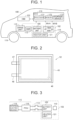
- FIG. 1 is a view schematically showing the overall configuration of a vehicle including a battery system according to an embodiment of the present disclosure.
- This vehicle is a battery electric vehicle (BEV), for example, and may also be another type of an electrified vehicle, such as a hybrid electric vehicle (HEV) including an engine.
- BEV battery electric vehicle
- HEV hybrid electric vehicle
- a vehicle 1 includes a battery case 102, a battery unit 105, a sensor unit 110, an SMR 112, a drive unit 115, driving wheels 119, a heater unit 121, a human machine interface (HMI) device 122, and an ECU 170.
- the battery case 102, the battery unit 105, the sensor unit 110, the SMR 112, the heater unit 121, the HMI device 122, and the ECU 170 form a "battery system" of the present disclosure.
- the battery case 102 accommodates the battery unit 105.
- the battery unit 105 is configured to be chargeable and dischargeable, and stores electric power for use in traveling of the vehicle 1.
- the battery unit 105 includes sulfide-based all-solid-state batteries.
- the all-solid-state battery refers to a battery having a solid electrolyte layer.
- the sulfide-based all-solid-state battery is an all-solid-state battery in which at least one of the material of a positive electrode active material layer of the battery unit 105 and the material of a solid electrolyte layer of the battery unit 105 contains a sulfur component.
- the battery unit 105 includes a plurality of (in this example, two) assembled batteries.
- FIG. 2 is a view schematically showing each cell of the assembled battery of the battery unit 105.
- each cell 52 includes a laminated film 45, an electrode body 46, a positive electrode tab 47, and a negative electrode tab 48.
- the electrode body 46 is sealed inside the laminated film 45.
- the positive electrode tab 47 and the negative electrode tab 48 are connected to the electrode body 46 and are drawn out from the inside of the laminated film 45.
- Each cell 52 is a sulfide-based all-solid-state battery.
- hydrogen sulfide gas can be generated inside the battery cells 25.
- gaps are formed in portions of the positive electrode tab 47 and the negative electrode tab 48, which are pulled out from the laminated film 45, and air might infiltrate into the laminated film 45 through the gaps.
- the solid electrolyte layer and water in the air might react with each other, thereby generating hydrogen sulfide gas.
- an internal short circuit might be caused inside the electrode body 46, and the electrode body 46 can have a high temperature, thereby generating hydrogen sulfide gas.
- the sulfide-based all-solid-state battery can generate hydrogen sulfide gas from itself.
- Such generation of hydrogen sulfide gas is unique to a sulfide-based all-solid-state battery, and is accelerated as the cell temperature becomes higher (the higher the cell temperature, the more the hydrogen sulfide gas is generated).
- FIG. 3 is a view explaining the connection relationship among the battery unit 105, the SMR 112, and the drive unit 115.
- the battery unit 105 is configured to be connectable to the drive unit 115 via the SMR 112.
- Organic solvents can be present outside the battery unit 105.
- the battery case 102 accommodates, in addition to the battery unit 105, components formed of various chemical materials including silicone rubber materials.
- the SMR 112 is connected between the battery unit 105 and the drive unit 115. Closing the SMR 112 corresponds to turning on the driving system of the vehicle 1. Opening the SMR 112 corresponds to turning off the driving system of the vehicle 1.
- the sensor unit 110 includes sensors 55A, 55B.
- Each of the sensors 55A, 55B is configured to measure a concentration of hydrogen sulfide (H2S) gas inside the battery case 102.
- Measured values of the sensors 55A, 55B are also expressed as measured values MVA and MVB, respectively.
- Each sensor can also react to different gases (miscellaneous gases) from the hydrogen sulfide gas. That is, each of the measured values MVA and MVB can also be affected by the miscellaneous gases.
- the drive unit 115 includes a power control unit (PCU) 116 and a rotating electric machine 118 (see FIG. 3 ).
- the PCU 116 is connected to the rotating electric machine 118.
- the PCU 116 is an electric power converter that converts direct current electric power supplied from the battery unit 105 via the SMR 112 into alternating current electric power, and supplies the alternating current electric power to the rotating electric machine 118.
- the rotating electric machine 118 is connected to the driving wheel 119 and receives the alternating current electric power from the PCU 116 to generate propulsive force (traveling driving force) for the vehicle 1.
- the heater unit 121 includes a plurality of (in this example, two) heaters and is configured to heat the battery unit 105.
- the HMI device 122 is a touch screen device, and functions as a notification device that receives various operations from a user of the vehicle 1 and provides notification to the user by displaying various screens thereon.
- the ECU 170 includes a processor 171, a memory 172, and a storage device 173.
- the processor 171 is, for example, a central processing unit (CPU), and executes various calculation processing.
- the memory 172 includes a read only memory (ROM) and a random access memory (RAM) (both not shown).
- the ROM stores programs executed by the processor 171.
- the storage device 173 stores various data.
- the ECU 170 controls various devices of the vehicle 1, such as the SMR 112, the PCU 116, the heater unit 121, the HMI device 122, and a solenoid on-off valve (described later).
- the ECU 170 opens and closes the SMR 112.
- the ECU 170 controls the PCU 116 and thereby to control charging electric power and discharging electric power of the battery unit 105.
- the ECU 150 sets an upper limit of the charging electric power and an upper limit of the discharging electric power.
- the ECU 150 sets these upper limits to be smaller and thereby to restrict the charging electric power and the discharging electric power. When the discharging electric power and the discharging electric power (charging-discharging of the battery unit 105) are restricted, generation of the hydrogen sulfide gas is reduced.
- the ECU 170 determines whether or not the hydrogen sulfide gas from the battery unit 105 is generated inside the battery case 102 based on the measured values MVA and MVB. For example, when both measured values MVA and MVB are less than a predetermined threshold value (described later), the ECU 170 determines that the hydrogen sulfide gas is not generated inside the battery case 102. On the other hand, when at least one of the measured values MVA and MVB is equal to or greater than the above threshold value, the ECU 170 determines that the hydrogen sulfide gas is generated inside the battery case 102. In this case, the ECU 170 executes a responsive control (described in detail later) to deal with the generation of the hydrogen sulfide gas from the battery unit 105.
- a responsive control described in detail later
- FIG. 4 is a perspective view of the battery case 102 and the battery unit 105.
- the battery case 102 accommodates two assembled batteries 50 (batteries 50A, 50B) included in the battery unit 105.
- the battery case 102 includes a lower case 91 and an upper case 92.
- the upper case 92 is formed with a respiratory membrane 61.
- the heater unit 121 includes heaters 30A, 30B.
- the heaters 30A, 30B are arranged below the batteries 50A, 50B, respectively.
- the heaters 30A, 30B heat the batteries 50A, 50B, respectively.
- the sensors 55A, 55B are arranged in the vicinities of the batteries 50A, 50B, respectively. In other words, the sensor 55A is closer to the battery 50A than the sensor 55B is, and the sensor 55B is closer to the battery 50B than the sensor 55A is.
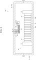
- FIG. 5 shows a section taken along line A-A in FIG. 4 .
- the assembled battery 50 in this example, the battery 50B
- the assembled battery 50B includes a plurality of cells 52.
- the plurality of cells 52 and the heater 30B are arranged between end plates 31, 32.
- the sensor 55B is disposed on the bottom surface of the lower case 91. This is because the hydrogen sulfide gas is heavier than the air.
- the battery case 102 (upper case 92) is provided with a duct 60, which is a communication passage that communicates the inside and the outside of the battery case 102.
- the duct 60 is provided with respiratory membranes 61, 62.
- Each of the respiratory membranes 61, 62 is made of an air-permeable and waterproof material. This material is, for example, a GORE-TEX (registered trademark) material.
- the internal space of the battery case 102 is almost sealed, but is not completely sealed because the duct 60 is provided with the respiratory membranes 61, 62.
- a desulfurizing agent 63 is disposed inside the duct 60.
- the air is exhausted from the inside to the outside of the battery case 102 through the duct 60 and the respiratory membranes 61, 62.
- the desulfurizing agent 63 adsorbs and purifies the hydrogen sulfide gas flowing from the inside to the outside of the battery case 102.
- the pressure inside the battery case 102 decreases, the air flows from the outside to the inside of the battery case 102 through the duct 60 and the respiratory membranes 61, 62.
- the duct 60 is provided with a solenoid on-off valve 65.
- the opening degree of the solenoid on-off valve 65 is adjusted in accordance with a command from the ECU 170. By adjusting this opening degree, the duct 60 can be opened or closed.
- Each of the duct 60 and the solenoid on-off valve 65 is included in the aforementioned battery system.
- the battery unit 105 (sulfide-based all-solid-state batteries) can generate the hydrogen sulfide gas inside the battery case 102.
- the hydrogen sulfide gas can be present, and the miscellaneous gases different from the hydrogen sulfide gas can also be present. This is because the air flowing from the outside to the inside of the battery case 102 through the duct 60 contains the miscellaneous gases, or the miscellaneous gases are generated from various materials accommodated in the battery case 102, organic solvents outside of the battery unit 105 (assembled batteries 50), or the materials configuring the respiratory membranes 61, 62.
- Each of the sensors 55A, 55B can react to the miscellaneous gases.
- measurement errors included in the measured values MVA and MVB might increase. Consequently, even though the hydrogen sulfide gas is not actually generated from the battery unit 105, at least one of the measured values MVA and MVB might be greater than the above-described threshold value.
- the hydrogen sulfide gas might be erroneously determined to be generated from the battery unit 105. Consequently, control, which is originally unnecessary, might be executed, so that the hydrogen sulfide gas might be dealt with excessively.
- the ECU 170 has a configuration to deal with the above problems. Specifically, the ECU 170 starts to drive the heater unit 121 (e.g., both heaters 30A, 30B) when at least one of the measured values MVA and MVB becomes greater than the first threshold value. After starting the driving of the heater unit 121, neither the measured values MVA nor MVB becomes greater than the second threshold value, the ECU 170 determines that the hydrogen sulfide gas is not generated from the battery unit 105 inside the battery case 102. On the other hand, when at least one of the measured values MVA and MVB becomes greater than the second threshold value, the ECU 170 determines that the hydrogen sulfide gas is generated from the battery unit 105 inside the battery case 102. Based on the result of this determination, the ECU 170 executes the responsive control (described in detail later) to deal with the generation of the hydrogen sulfide gas from the battery unit 105.
- the second threshold value is higher than the first threshold value.
- the generation of the hydrogen sulfide gas is accelerated due to heating of the battery unit 105 (increase in cell temperature) after starting the driving of the heater unit 121.
- the amount of the hydrogen sulfide gas generated from the battery unit 105 increases, and the hydrogen sulfide gas concentration inside the battery case 102 further increases.
- at least one of the measured values MVA and MVB becomes greater than the second threshold value.
- the concentration of the miscellaneous gases inside the battery case 102 has no relation with the increase in temperature of the battery unit 105; therefore, the concentration does not increase in response to starting the driving of the heater unit 121.
- the responsive control includes at least one of; opening the SMR 112 (turning off the driving system); opening the solenoid on-off valve 65; controlling the HMI device 122 to notify the user of generation of the hydrogen sulfide gas inside the battery case 102; and controlling the PCU 116 to restrict the charging-discharge of the battery unit 105.
- the battery unit 105 By opening the SMR 112, the battery unit 105 can be separated from the PCU 116. Thereby, the battery unit 105 becomes electrically independent and its conduction with the other components of the vehicle 1 is cut off. As a result, the charging-discharging is stopped (the vehicle 1 is stopped), and the generation of the hydrogen sulfide gas is reduced. By opening the solenoid on-off valve 65, the hydrogen sulfide gas can be discharged from the inside to the outside of the battery case 102 through the duct 60. By controlling the HMI device 122 as described above, the user is notified of the generation of the hydrogen sulfide gas.
- the user can be motivated to deal with the generation of the hydrogen sulfide gas (for example, to use the maintenance service for the vehicle 1).
- the PCU 116 By controlling the PCU 116 as described above, the charging-discharging of the battery unit 105 is restricted. Thereby, the generation of the hydrogen sulfide gas is reduced. In this manner, according to the responsive control, it is possible to deal with the generation of the hydrogen sulfide gas inside the battery case 102.
- the second threshold value is greater than 1 ppm and less than 5 ppm, for example.
- the first threshold value is set to be 1 ppm and the second threshold value is set to be 3 ppm.
- the control concentration and the permissible concentration of the hydrogen sulfide gas should be 1 ppm and 5 ppm, respectively.
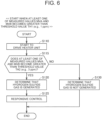
- FIG. 6 is a flowchart exemplifying the processing and the control executed by the ECU 170 in the embodiment. This flowchart is started when at least one of the measured values MVA and MVB becomes greater than a threshold value TH1.
- the threshold value TH1 corresponds to the first threshold value.
- the ECU 170 starts to drive the heater unit 121 (S 110), and thereafter determines whether or not at least one of the measured values MVA and MVB becomes greater than a threshold value TH2 (S115).
- the threshold value TH2 corresponds to the second threshold value.
- the ECU 170 determines that the hydrogen sulfide gas is generated inside the battery case 102 (S120), and executes the above-described responsive control (S125).
- the ECU 170 determines that the hydrogen sulfide gas is not generated inside the battery case 102 (S130). In this case, it can be considered that the sensor unit 110 simply has simply reacted to the miscellaneous gases. After S125 or S130, the process is ended.
- the embodiment it is possible to determine whether or not the hydrogen sulfide gas is generated with high precision. In addition, it is possible to avoid that the hydrogen sulfide gas generated from the battery unit 105 is dealt with excessively.
- the ECU 170 drives both heaters 30A, 30B; however, from the viewpoint of reduction in electric power consumption, only one of these heaters may be driven.
- the ECU 170 starts to drive only the heater 30A of the heaters 30A, 30B when the measured value MVA becomes greater than the threshold value TH1 earlier than the measured value MVB does.
- the sensor 55A is disposed closer to the battery 50A than the sensor 55B is. Therefore, when the measured value MVA becomes greater than the threshold value TH1 earlier than the measured value MVB does, it can be considered that the hydrogen sulfide gas is generated from the battery 50A rather than the battery 50B. Therefore, in order to promote the generation of the hydrogen sulfide gas from the battery 50A (battery unit 105), it is sufficient to start to drive only the heater 30A of the heaters 30A, 30B; and it may also be considered that it is not necessarily required to drive both heaters.
- FIG. 7 is a flowchart exemplifying the processing and the control performed by the ECU 170 in this modification. This flowchart is started when either the measured values MVA or MVB becomes greater than the threshold value TH1.
- the ECU 170 determines whether or not the measured value MVA becomes greater than the threshold value TH1 earlier than the measured value MVB does; that is, whether or not the measured value greater than the threshold value TH1 is the measured value MVA (S205).
- the ECU 170 When the measured value MVA becomes greater than the threshold value TH1 earlier than the measured value MVB does (YES in S205), the ECU 170 starts to drive the heater 30A (S210), and then determines whether or not the measured value MVA becomes greater than the threshold value TH2 (S215). When the measured value MVA does not become greater than the threshold value TH2 (NO in S215), the ECU 170 determines that the hydrogen sulfide gas is not generated inside the battery case 102 (S230). When the measured value MVA becomes greater than the threshold value TH2 (YES in S215), the ECU 170 determines that the hydrogen sulfide gas is generated (S220), and then executes the responsive control (S225).
- the ECU 170 When the measured value MVB becomes greater than the threshold value TH1 earlier than the measured value MVA does; that is, when the measured value greater than the threshold value TH1 is the measured value MVB (NO in S205), the ECU 170 starts to drive the heater 30B. (S212). Subsequently, the ECU 170 determines whether or not the measured value MVB becomes greater than the threshold value TH2 (S217). When the measured value MVB becomes greater than the threshold value TH2 (YES in S217), the process proceeds to S220. When the measured value MVB does not become greater than the threshold value TH2 (NO in S217), the process proceeds to S230.
- the sensor unit 110 is configured to include both sensors 55A, 55B; however, the sensor unit may not include these two sensors but may include a single sensor that measures the concentration of the hydrogen sulfide gas inside the battery case 102.
- the ECU 170 starts to drive the heater unit 121 (e.g., the heater 30A) when the measured value of this sensor becomes greater than the threshold value TH1.
- the ECU 170 determines whether or not this measured value becomes greater than the threshold value TH2. When this measured value does not become greater than the threshold value TH2, the ECU 170 determines that the hydrogen sulfide gas is not generated inside the battery case 102.
- the ECU 170 determines that the hydrogen sulfide gas is generated and executes the responsive control.
Landscapes
- Engineering & Computer Science (AREA)
- Chemical & Material Sciences (AREA)
- General Chemical & Material Sciences (AREA)
- Electrochemistry (AREA)
- Chemical Kinetics & Catalysis (AREA)
- Manufacturing & Machinery (AREA)
- Life Sciences & Earth Sciences (AREA)
- Power Engineering (AREA)
- Health & Medical Sciences (AREA)
- Sustainable Development (AREA)
- Mechanical Engineering (AREA)
- Transportation (AREA)
- Sustainable Energy (AREA)
- Physics & Mathematics (AREA)
- General Physics & Mathematics (AREA)
- Pathology (AREA)
- Combustion & Propulsion (AREA)
- Immunology (AREA)
- General Health & Medical Sciences (AREA)
- Medicinal Chemistry (AREA)
- Food Science & Technology (AREA)
- Biochemistry (AREA)
- Analytical Chemistry (AREA)
- Secondary Cells (AREA)
- Microelectronics & Electronic Packaging (AREA)
- Electromagnetism (AREA)
- Automation & Control Theory (AREA)
- Condensed Matter Physics & Semiconductors (AREA)
- Inorganic Chemistry (AREA)
- Electric Propulsion And Braking For Vehicles (AREA)
Abstract
A battery system includes a battery unit, a heater unit, and a sensor unit. The battery unit is accommodated in a battery case and includes sulfide-based all-solid-state batteries. The heater unit is configured to heat the battery unit. The sensor unit is configured to measure a hydrogen sulfide gas concentration inside the battery case. The heater unit is started to be driven when a measured value of the sensor unit becomes greater than the first threshold value. After starting the driving of the heater unit, when the measured value becomes greater than the second threshold value that is higher than the first threshold value, a responsive control is executed to deal with generation of the hydrogen sulfide gas from the sulfide-based all-solid-state batteries.
Description
- The present invention relates to a battery system.
-
Japanese Unexamined Application Publication No. 2022-46077 - Sulfide-based all-solid-state batteries can generate hydrogen sulfide gas inside the battery case. Inside the battery case, hydrogen sulfide gas can be present, and miscellaneous gases different from the hydrogen sulfide gas can also be present. When the sensor reacts to the miscellaneous gases, measurement errors in the sensor can be increased. As a result, the measured value of the sensor might become greater than the threshold value even when hydrogen sulfide is not actually generated from the sulfide-based all-solid-state batteries. In this case, it might be erroneously determined that the hydrogen sulfide gas is generated from the sulfide-based all-solid-state batteries. Consequently, control, which is originally unnecessary, might be executed, so that the hydrogen sulfide gas from the sulfide-based all-solid-state batteries might be dealt with excessively.
- The present disclosure has been made in order to solve the above problems, and an object of the present disclosure is to avoid that hydrogen sulfide gas from sulfide-based all-solid-state batteries is dealt with excessively.
- A battery system of the present disclosure includes a battery unit, a heater unit, and a sensor unit. The battery unit is accommodated in a battery case and includes a sulfide-based all-solid-state battery. The heater unit is configured to heat the battery unit. The sensor unit is configured to measure a hydrogen sulfide gas concentration inside the battery case. The heater unit is started to be driven when a measured value of the sensor unit becomes greater than the first threshold value. After starting the driving of the heater unit, when the measured value becomes greater than the second threshold value that is higher than the first threshold value, a responsive control is executed to deal with generation of the hydrogen sulfide gas from the sulfide-based all-solid-state battery.
- According to the present disclosure, it is possible to avoid that hydrogen sulfide gas from the sulfide-based all-solid-state batteries is dealt with excessively.
- Features, advantages, and technical and industrial significance of exemplary embodiments of the invention will be described below with reference to the accompanying drawings, in which like signs denote like elements, and wherein:
-
FIG. 1 is a view schematically showing the overall configuration of a vehicle including a battery system according to an embodiment of the present disclosure; -
FIG. 2 is a view schematically showing each cell of an assembled battery of a battery unit; -
FIG. 3 is a view explaining the connection relationship among the battery unit, an SMR (system main relay), and a drive unit; -
FIG. 4 is a perspective view of the battery case and the battery unit; -
FIG. 5 shows a section taken along line A-A inFIG. 4 ; -
FIG. 6 is a flowchart exemplifying processing and control executed by an ECU (electronic control unit) in the embodiment; and -
FIG. 7 is a flowchart exemplifying processing and control executed by the ECU in a modification. - Hereinafter, embodiments of the present disclosure will be described in detail with reference to the drawings. The same or corresponding parts in the drawings are designated by the same reference numerals, and the description thereof will not be repeated. The embodiments and their modifications may be combined with each other as appropriate.
-
FIG. 1 is a view schematically showing the overall configuration of a vehicle including a battery system according to an embodiment of the present disclosure. This vehicle is a battery electric vehicle (BEV), for example, and may also be another type of an electrified vehicle, such as a hybrid electric vehicle (HEV) including an engine. - With reference to
FIG. 1 , avehicle 1 includes abattery case 102, abattery unit 105, asensor unit 110, anSMR 112, adrive unit 115,driving wheels 119, aheater unit 121, a human machine interface (HMI)device 122, and anECU 170. Thebattery case 102, thebattery unit 105, thesensor unit 110, theSMR 112, theheater unit 121, theHMI device 122, and theECU 170 form a "battery system" of the present disclosure. - The
battery case 102 accommodates thebattery unit 105. Thebattery unit 105 is configured to be chargeable and dischargeable, and stores electric power for use in traveling of thevehicle 1. Thebattery unit 105 includes sulfide-based all-solid-state batteries. The all-solid-state battery refers to a battery having a solid electrolyte layer. The sulfide-based all-solid-state battery is an all-solid-state battery in which at least one of the material of a positive electrode active material layer of thebattery unit 105 and the material of a solid electrolyte layer of thebattery unit 105 contains a sulfur component. Thebattery unit 105 includes a plurality of (in this example, two) assembled batteries. -
FIG. 2 is a view schematically showing each cell of the assembled battery of thebattery unit 105. With reference toFIG. 2 , eachcell 52 includes a laminatedfilm 45, anelectrode body 46, apositive electrode tab 47, and anegative electrode tab 48. Theelectrode body 46 is sealed inside the laminatedfilm 45. Thepositive electrode tab 47 and thenegative electrode tab 48 are connected to theelectrode body 46 and are drawn out from the inside of the laminatedfilm 45. Eachcell 52 is a sulfide-based all-solid-state battery. - When charging-discharging of the
battery unit 105 is repeated, hydrogen sulfide gas can be generated inside thebattery cells 25. For example, gaps are formed in portions of thepositive electrode tab 47 and thenegative electrode tab 48, which are pulled out from the laminatedfilm 45, and air might infiltrate into the laminatedfilm 45 through the gaps. As a result, the solid electrolyte layer and water in the air might react with each other, thereby generating hydrogen sulfide gas. In another case, an internal short circuit might be caused inside theelectrode body 46, and theelectrode body 46 can have a high temperature, thereby generating hydrogen sulfide gas. In this manner, the sulfide-based all-solid-state battery can generate hydrogen sulfide gas from itself. Such generation of hydrogen sulfide gas is unique to a sulfide-based all-solid-state battery, and is accelerated as the cell temperature becomes higher (the higher the cell temperature, the more the hydrogen sulfide gas is generated). -
FIG. 3 is a view explaining the connection relationship among thebattery unit 105, theSMR 112, and thedrive unit 115. With reference toFIG. 3 , thebattery unit 105 is configured to be connectable to thedrive unit 115 via theSMR 112. Organic solvents can be present outside thebattery unit 105. Thebattery case 102 accommodates, in addition to thebattery unit 105, components formed of various chemical materials including silicone rubber materials. - The
SMR 112 is connected between thebattery unit 105 and thedrive unit 115. Closing theSMR 112 corresponds to turning on the driving system of thevehicle 1. Opening theSMR 112 corresponds to turning off the driving system of thevehicle 1. - With reference to
FIG. 1 again, thesensor unit 110 includessensors sensors battery case 102. Measured values of thesensors - The
drive unit 115 includes a power control unit (PCU) 116 and a rotating electric machine 118 (seeFIG. 3 ). ThePCU 116 is connected to the rotatingelectric machine 118. ThePCU 116 is an electric power converter that converts direct current electric power supplied from thebattery unit 105 via theSMR 112 into alternating current electric power, and supplies the alternating current electric power to the rotatingelectric machine 118. The rotatingelectric machine 118 is connected to thedriving wheel 119 and receives the alternating current electric power from thePCU 116 to generate propulsive force (traveling driving force) for thevehicle 1. Theheater unit 121 includes a plurality of (in this example, two) heaters and is configured to heat thebattery unit 105. - The
HMI device 122 is a touch screen device, and functions as a notification device that receives various operations from a user of thevehicle 1 and provides notification to the user by displaying various screens thereon. - The
ECU 170 includes aprocessor 171, amemory 172, and astorage device 173. Theprocessor 171 is, for example, a central processing unit (CPU), and executes various calculation processing. Thememory 172 includes a read only memory (ROM) and a random access memory (RAM) (both not shown). The ROM stores programs executed by theprocessor 171. Thestorage device 173 stores various data. - The
ECU 170 controls various devices of thevehicle 1, such as theSMR 112, thePCU 116, theheater unit 121, theHMI device 122, and a solenoid on-off valve (described later). TheECU 170 opens and closes theSMR 112. TheECU 170 controls thePCU 116 and thereby to control charging electric power and discharging electric power of thebattery unit 105. The ECU 150 sets an upper limit of the charging electric power and an upper limit of the discharging electric power. The ECU 150 sets these upper limits to be smaller and thereby to restrict the charging electric power and the discharging electric power. When the discharging electric power and the discharging electric power (charging-discharging of the battery unit 105) are restricted, generation of the hydrogen sulfide gas is reduced. - The
ECU 170 determines whether or not the hydrogen sulfide gas from thebattery unit 105 is generated inside thebattery case 102 based on the measured values MVA and MVB. For example, when both measured values MVA and MVB are less than a predetermined threshold value (described later), theECU 170 determines that the hydrogen sulfide gas is not generated inside thebattery case 102. On the other hand, when at least one of the measured values MVA and MVB is equal to or greater than the above threshold value, theECU 170 determines that the hydrogen sulfide gas is generated inside thebattery case 102. In this case, theECU 170 executes a responsive control (described in detail later) to deal with the generation of the hydrogen sulfide gas from thebattery unit 105. -
FIG. 4 is a perspective view of thebattery case 102 and thebattery unit 105. With reference toFIG. 4 , thebattery case 102 accommodates two assembled batteries 50 (batteries battery unit 105. Thebattery case 102 includes alower case 91 and anupper case 92. Theupper case 92 is formed with arespiratory membrane 61. - The
heater unit 121 includesheaters heaters batteries heaters batteries - The
sensors batteries sensor 55A is closer to thebattery 50A than thesensor 55B is, and thesensor 55B is closer to thebattery 50B than thesensor 55A is. -
FIG. 5 shows a section taken along line A-A inFIG. 4 . With reference toFIG. 5 , the assembled battery 50 (in this example, thebattery 50B) includes a plurality ofcells 52. The plurality ofcells 52 and theheater 30B are arranged betweenend plates sensor 55B is disposed on the bottom surface of thelower case 91. This is because the hydrogen sulfide gas is heavier than the air. - The battery case 102 (upper case 92) is provided with a
duct 60, which is a communication passage that communicates the inside and the outside of thebattery case 102. Theduct 60 is provided withrespiratory membranes respiratory membranes battery case 102 is almost sealed, but is not completely sealed because theduct 60 is provided with therespiratory membranes agent 63 is disposed inside theduct 60. - When the pressure inside the
battery case 102 increases, the air is exhausted from the inside to the outside of thebattery case 102 through theduct 60 and therespiratory membranes battery case 102, the desulfurizingagent 63 adsorbs and purifies the hydrogen sulfide gas flowing from the inside to the outside of thebattery case 102. On the other hand, when the pressure inside thebattery case 102 decreases, the air flows from the outside to the inside of thebattery case 102 through theduct 60 and therespiratory membranes - The
duct 60 is provided with a solenoid on-offvalve 65. The opening degree of the solenoid on-offvalve 65 is adjusted in accordance with a command from theECU 170. By adjusting this opening degree, theduct 60 can be opened or closed. Each of theduct 60 and the solenoid on-offvalve 65 is included in the aforementioned battery system. - As described above, the battery unit 105 (sulfide-based all-solid-state batteries) can generate the hydrogen sulfide gas inside the
battery case 102. Inside thebattery case 102, the hydrogen sulfide gas can be present, and the miscellaneous gases different from the hydrogen sulfide gas can also be present. This is because the air flowing from the outside to the inside of thebattery case 102 through theduct 60 contains the miscellaneous gases, or the miscellaneous gases are generated from various materials accommodated in thebattery case 102, organic solvents outside of the battery unit 105 (assembled batteries 50), or the materials configuring therespiratory membranes - Each of the
sensors battery unit 105, at least one of the measured values MVA and MVB might be greater than the above-described threshold value. Hence, the hydrogen sulfide gas might be erroneously determined to be generated from thebattery unit 105. Consequently, control, which is originally unnecessary, might be executed, so that the hydrogen sulfide gas might be dealt with excessively. In order to avoid the above erroneous determination, it seems to be preferable to provide thevehicle 1 with a high-precision hydrogen sulfide gas concentration sensor, which has low reactivity to the miscellaneous gases (only the hydrogen sulfide gas can be measured with high precision). However, this solution causes increase in cost. - In the embodiment, the
ECU 170 has a configuration to deal with the above problems. Specifically, theECU 170 starts to drive the heater unit 121 (e.g., bothheaters heater unit 121, neither the measured values MVA nor MVB becomes greater than the second threshold value, theECU 170 determines that the hydrogen sulfide gas is not generated from thebattery unit 105 inside thebattery case 102. On the other hand, when at least one of the measured values MVA and MVB becomes greater than the second threshold value, theECU 170 determines that the hydrogen sulfide gas is generated from thebattery unit 105 inside thebattery case 102. Based on the result of this determination, theECU 170 executes the responsive control (described in detail later) to deal with the generation of the hydrogen sulfide gas from thebattery unit 105. The second threshold value is higher than the first threshold value. - By configuring as described above, when the
battery unit 105 actually generates the hydrogen sulfide gas, the generation of the hydrogen sulfide gas is accelerated due to heating of the battery unit 105 (increase in cell temperature) after starting the driving of theheater unit 121. The amount of the hydrogen sulfide gas generated from thebattery unit 105 increases, and the hydrogen sulfide gas concentration inside thebattery case 102 further increases. As a result, at least one of the measured values MVA and MVB becomes greater than the second threshold value. In the meantime, the concentration of the miscellaneous gases inside thebattery case 102 has no relation with the increase in temperature of thebattery unit 105; therefore, the concentration does not increase in response to starting the driving of theheater unit 121. According to the above configuration, it is possible to avoid an erroneous determination that the hydrogen sulfide gas is generated. Furthermore, it is not necessarily required to use a high-precision hydrogen sulfide gas concentration sensor. In addition, it is possible to avoid that the responsive control is unnecessarily started due to the reaction of thesensors battery unit 105 is dealt with excessively. - An example of the responsive control will be described below. The responsive control includes at least one of; opening the SMR 112 (turning off the driving system); opening the solenoid on-off
valve 65; controlling theHMI device 122 to notify the user of generation of the hydrogen sulfide gas inside thebattery case 102; and controlling thePCU 116 to restrict the charging-discharge of thebattery unit 105. - By opening the
SMR 112, thebattery unit 105 can be separated from thePCU 116. Thereby, thebattery unit 105 becomes electrically independent and its conduction with the other components of thevehicle 1 is cut off. As a result, the charging-discharging is stopped (thevehicle 1 is stopped), and the generation of the hydrogen sulfide gas is reduced. By opening the solenoid on-offvalve 65, the hydrogen sulfide gas can be discharged from the inside to the outside of thebattery case 102 through theduct 60. By controlling theHMI device 122 as described above, the user is notified of the generation of the hydrogen sulfide gas. Accordingly, the user can be motivated to deal with the generation of the hydrogen sulfide gas (for example, to use the maintenance service for the vehicle 1). By controlling thePCU 116 as described above, the charging-discharging of thebattery unit 105 is restricted. Thereby, the generation of the hydrogen sulfide gas is reduced. In this manner, according to the responsive control, it is possible to deal with the generation of the hydrogen sulfide gas inside thebattery case 102. - The first threshold value is equal to or less than 1 ppm (1 ppm = 0.0001%), for example. The second threshold value is greater than 1 ppm and less than 5 ppm, for example. In the embodiment, the first threshold value is set to be 1 ppm and the second threshold value is set to be 3 ppm.
- Generally, the control concentration and the permissible concentration of the hydrogen sulfide gas should be 1 ppm and 5 ppm, respectively. With the above configuration, even after at least one of the measured values MVA and MVB becomes greater than the second threshold value (3 ppm) after starting the driving of the
heater unit 121, it is possible to avoid that the hydrogen sulfide gas concentration becomes more than the permissible concentration (5 ppm). Thereby, it is possible to accurately determine whether or not the hydrogen sulfide gas is generated without causing the hydrogen sulfide gas concentration to become more than the permissible concentration. -
FIG. 6 is a flowchart exemplifying the processing and the control executed by theECU 170 in the embodiment. This flowchart is started when at least one of the measured values MVA and MVB becomes greater than a threshold value TH1. The threshold value TH1 corresponds to the first threshold value. - With reference to
FIG. 6 , theECU 170 starts to drive the heater unit 121 (S 110), and thereafter determines whether or not at least one of the measured values MVA and MVB becomes greater than a threshold value TH2 (S115). The threshold value TH2 corresponds to the second threshold value. - When at least one of the measured values MVA and MVB becomes greater than the threshold value TH2 (YES in S115), the
ECU 170 determines that the hydrogen sulfide gas is generated inside the battery case 102 (S120), and executes the above-described responsive control (S125). On the other hand, when neither the measured values MVA nor MVB becomes greater than the threshold value TH2 (NO in S115), theECU 170 determines that the hydrogen sulfide gas is not generated inside the battery case 102 (S130). In this case, it can be considered that thesensor unit 110 simply has simply reacted to the miscellaneous gases. After S125 or S130, the process is ended. - As described above, according to the embodiment, it is possible to determine whether or not the hydrogen sulfide gas is generated with high precision. In addition, it is possible to avoid that the hydrogen sulfide gas generated from the
battery unit 105 is dealt with excessively. - With reference to
FIG. 4 again, in the embodiment, theECU 170 drives bothheaters ECU 170 starts to drive only theheater 30A of theheaters - As mentioned above, the
sensor 55A is disposed closer to thebattery 50A than thesensor 55B is. Therefore, when the measured value MVA becomes greater than the threshold value TH1 earlier than the measured value MVB does, it can be considered that the hydrogen sulfide gas is generated from thebattery 50A rather than thebattery 50B. Therefore, in order to promote the generation of the hydrogen sulfide gas from thebattery 50A (battery unit 105), it is sufficient to start to drive only theheater 30A of theheaters heater 30A alone as described above, reduction in electric power consumption in theheater unit 121 can be attained compared to the embodiment in which bothheaters heater 30A, the generation of the hydrogen sulfide gas from thebattery 50A is promoted, and the measured value MVA can become greater than the threshold value TH2. As a result, it is determined that the hydrogen sulfide gas is generated from thebattery 50A, and the responsive control is then executed. -
FIG. 7 is a flowchart exemplifying the processing and the control performed by theECU 170 in this modification. This flowchart is started when either the measured values MVA or MVB becomes greater than the threshold value TH1. - With reference to
FIG. 7 , theECU 170 determines whether or not the measured value MVA becomes greater than the threshold value TH1 earlier than the measured value MVB does; that is, whether or not the measured value greater than the threshold value TH1 is the measured value MVA (S205). - When the measured value MVA becomes greater than the threshold value TH1 earlier than the measured value MVB does (YES in S205), the
ECU 170 starts to drive theheater 30A (S210), and then determines whether or not the measured value MVA becomes greater than the threshold value TH2 (S215). When the measured value MVA does not become greater than the threshold value TH2 (NO in S215), theECU 170 determines that the hydrogen sulfide gas is not generated inside the battery case 102 (S230). When the measured value MVA becomes greater than the threshold value TH2 (YES in S215), theECU 170 determines that the hydrogen sulfide gas is generated (S220), and then executes the responsive control (S225). - When the measured value MVB becomes greater than the threshold value TH1 earlier than the measured value MVA does; that is, when the measured value greater than the threshold value TH1 is the measured value MVB (NO in S205), the
ECU 170 starts to drive theheater 30B. (S212). Subsequently, theECU 170 determines whether or not the measured value MVB becomes greater than the threshold value TH2 (S217). When the measured value MVB becomes greater than the threshold value TH2 (YES in S217), the process proceeds to S220. When the measured value MVB does not become greater than the threshold value TH2 (NO in S217), the process proceeds to S230. - As described above, according to this modification, it is possible to reduce the electric power consumption of the
heater unit 121. - The
sensor unit 110 is configured to include bothsensors battery case 102. In this case, theECU 170 starts to drive the heater unit 121 (e.g., theheater 30A) when the measured value of this sensor becomes greater than the threshold value TH1. After starting the driving of theheater unit 121, theECU 170 determines whether or not this measured value becomes greater than the threshold value TH2. When this measured value does not become greater than the threshold value TH2, theECU 170 determines that the hydrogen sulfide gas is not generated inside thebattery case 102. On the other hand, when the measured value becomes greater than the threshold value TH2, theECU 170 determines that the hydrogen sulfide gas is generated and executes the responsive control. - It should be considered that the embodiments disclosed herein are illustrative in all respects and are not restrictive. The scope of the present invention is indicated by the claims rather than the above description, and it is intended that all changes within the meaning and the scope equivalent to the claims are included.
Claims (4)
- A battery system comprising:
a battery unit accommodated in a battery case, the battery unit including a sulfide-based all-solid-state battery;a heater unit configured to heat the battery unit; anda sensor unit configured to measure a hydrogen sulfide gas concentration inside the battery case,the heater unit being started to be driven when a measured value of the sensor unit becomes greater than a first threshold value,after starting the driving of the heater unit, when the measured value becomes greater than a second threshold value that is higher than the first threshold value, a responsive control to deal with generation of the hydrogen sulfide gas from the sulfide-based all-solid-state battery being executed. - The battery system according to claim 1, whereinthe battery unit includes a first battery and a second battery,the heater unit includes a first heater that heats the first battery, and a second heater that heats the second battery,the sensor unit includes a first sensor and a second sensor each of which is configured to measure the hydrogen sulfide gas concentration, the first sensor is disposed in a vicinity of the first battery, and the second sensor is disposed in a vicinity of the second battery, andwhen the measured value of the first sensor becomes greater than the first threshold value earlier than the measured value of the second sensor does, only the first heater of the first heater and the second heater is started to be driven.
- The battery system according to claim 1 or 2, whereinthe battery unit is configured to be chargeable and dischargeable and is configured to be connectable via a relay device to an electric power converter connected to a rotating electric machine that generates propulsive force of an electrified vehicle,the battery system further includes:a communication passage that communicates an inside and an outside of the battery case;an on-off valve provided to the communication passage; anda notification device that provides notification to a user of the electrified vehicle, andthe responsive control includes at least one of:opening the relay device;opening the on-off valve;controlling the notification device to notify the user of the generation of the hydrogen sulfide gas inside the battery case; andcontrolling the electric power converter to restrict charging-discharge of the battery unit.
- The battery system according to claim 1 or 2, wherein:the first threshold value is equal to or less than 1 ppm; andthe second threshold value is greater than 1 ppm and less than 5 ppm.
Applications Claiming Priority (1)
| Application Number | Priority Date | Filing Date | Title |
|---|---|---|---|
| JP2023095604A JP7852579B2 (en) | 2023-06-09 | 2023-06-09 | Battery system |
Publications (1)
| Publication Number | Publication Date |
|---|---|
| EP4475278A1 true EP4475278A1 (en) | 2024-12-11 |
Family
ID=90904769
Family Applications (1)
| Application Number | Title | Priority Date | Filing Date |
|---|---|---|---|
| EP24172376.6A Pending EP4475278A1 (en) | 2023-06-09 | 2024-04-25 | Battery system |
Country Status (4)
| Country | Link |
|---|---|
| US (1) | US20240413415A1 (en) |
| EP (1) | EP4475278A1 (en) |
| JP (1) | JP7852579B2 (en) |
| CN (1) | CN119108683A (en) |
Families Citing this family (1)
| Publication number | Priority date | Publication date | Assignee | Title |
|---|---|---|---|---|
| JP7851169B2 (en) * | 2022-03-30 | 2026-04-24 | 本田技研工業株式会社 | Hydrogen sulfide absorption device |
Citations (3)
| Publication number | Priority date | Publication date | Assignee | Title |
|---|---|---|---|---|
| JP2022012308A (en) * | 2020-07-01 | 2022-01-17 | トヨタ自動車株式会社 | Cell system |
| JP2022046077A (en) | 2020-09-10 | 2022-03-23 | 日産自動車株式会社 | Battery system and battery cooling method |
| JP2022098799A (en) * | 2020-12-22 | 2022-07-04 | 日産自動車株式会社 | Battery system and control method of lithium ion secondary battery |
Family Cites Families (3)
| Publication number | Priority date | Publication date | Assignee | Title |
|---|---|---|---|---|
| JP3276288B2 (en) * | 1996-03-19 | 2002-04-22 | 勝夫 江原 | Method and apparatus for detecting leakage from lithium battery |
| US8729866B2 (en) * | 2009-09-02 | 2014-05-20 | Toyota Jidosha Kabushiki Kaisha | Sulfide-based all-solid-state lithium secondary battery system |
| JP2014086226A (en) * | 2012-10-22 | 2014-05-12 | Toyota Motor Corp | All-solid-state battery system |
-
2023
- 2023-06-09 JP JP2023095604A patent/JP7852579B2/en active Active
-
2024
- 2024-04-17 US US18/637,677 patent/US20240413415A1/en active Pending
- 2024-04-25 EP EP24172376.6A patent/EP4475278A1/en active Pending
- 2024-05-09 CN CN202410567180.5A patent/CN119108683A/en active Pending
Patent Citations (3)
| Publication number | Priority date | Publication date | Assignee | Title |
|---|---|---|---|---|
| JP2022012308A (en) * | 2020-07-01 | 2022-01-17 | トヨタ自動車株式会社 | Cell system |
| JP2022046077A (en) | 2020-09-10 | 2022-03-23 | 日産自動車株式会社 | Battery system and battery cooling method |
| JP2022098799A (en) * | 2020-12-22 | 2022-07-04 | 日産自動車株式会社 | Battery system and control method of lithium ion secondary battery |
Also Published As
| Publication number | Publication date |
|---|---|
| JP7852579B2 (en) | 2026-04-28 |
| JP2024176798A (en) | 2024-12-19 |
| CN119108683A (en) | 2024-12-10 |
| US20240413415A1 (en) | 2024-12-12 |
Similar Documents
| Publication | Publication Date | Title |
|---|---|---|
| JP5023374B2 (en) | Fuel cell system | |
| JP4265629B2 (en) | Secondary battery charge / discharge control device and hybrid vehicle equipped with the same | |
| EP4475278A1 (en) | Battery system | |
| EP1668728A1 (en) | Abnormality detecting device of fuel cell system | |
| JP2021034149A (en) | Display control device, display control method, and program | |
| CN101489821A (en) | moving body | |
| JP3935056B2 (en) | Control device for fuel cell vehicle | |
| JP6520633B2 (en) | Vehicle control system | |
| CN112744127A (en) | Vehicle system, vehicle control method, and storage medium | |
| CN105609830B (en) | Fuel cell system and its control method | |
| US20250297906A1 (en) | Road surface interference sensor and monitoring system | |
| JP2006278276A (en) | Fuel cell system, control method thereof, and vehicle equipped with the same | |
| CN119315146A (en) | Battery Pack and Vehicle | |
| US11660982B2 (en) | Method of controlling fuel cell vehicle and the fuel cell vehicle | |
| JP2016180653A (en) | Voltage detector | |
| US20240405302A1 (en) | Power storage device and vehicle | |
| JP2007149450A (en) | FUEL CELL SYSTEM, MOBILE BODY AND ITS STARTING METHOD | |
| JP7743846B2 (en) | Battery System | |
| JP5204465B2 (en) | Fuel cell system | |
| US20240300298A1 (en) | Vehicle, control device, and vehicle control method | |
| KR102958927B1 (en) | Vehicle, control device, and vehicle control method | |
| JP6977611B2 (en) | Vehicles equipped with multiple fuel cell units | |
| JP2019122200A (en) | Electric vehicle charge control device | |
| WO2019138805A1 (en) | Vehicle control device | |
| US20240227626A1 (en) | Travel control device for fuel cell vehicle |
Legal Events
| Date | Code | Title | Description |
|---|---|---|---|
| PUAI | Public reference made under article 153(3) epc to a published international application that has entered the european phase |
Free format text: ORIGINAL CODE: 0009012 |
|
| STAA | Information on the status of an ep patent application or granted ep patent |
Free format text: STATUS: REQUEST FOR EXAMINATION WAS MADE |
|
| 17P | Request for examination filed |
Effective date: 20240509 |
|
| AK | Designated contracting states |
Kind code of ref document: A1 Designated state(s): AL AT BE BG CH CY CZ DE DK EE ES FI FR GB GR HR HU IE IS IT LI LT LU LV MC ME MK MT NL NO PL PT RO RS SE SI SK SM TR |