EP4475266A1 - Energy storage system with enhanced safety - Google Patents
Energy storage system with enhanced safety Download PDFInfo
- Publication number
- EP4475266A1 EP4475266A1 EP23799743.2A EP23799743A EP4475266A1 EP 4475266 A1 EP4475266 A1 EP 4475266A1 EP 23799743 A EP23799743 A EP 23799743A EP 4475266 A1 EP4475266 A1 EP 4475266A1
- Authority
- EP
- European Patent Office
- Prior art keywords
- sub
- state
- control unit
- main
- line
- Prior art date
- Legal status (The legal status is an assumption and is not a legal conclusion. Google has not performed a legal analysis and makes no representation as to the accuracy of the status listed.)
- Pending
Links
Images




Classifications
-
- H—ELECTRICITY
- H01—ELECTRIC ELEMENTS
- H01M—PROCESSES OR MEANS, e.g. BATTERIES, FOR THE DIRECT CONVERSION OF CHEMICAL ENERGY INTO ELECTRICAL ENERGY
- H01M10/00—Secondary cells; Manufacture thereof
- H01M10/42—Methods or arrangements for servicing or maintenance of secondary cells or secondary half-cells
-
- H—ELECTRICITY
- H01—ELECTRIC ELEMENTS
- H01M—PROCESSES OR MEANS, e.g. BATTERIES, FOR THE DIRECT CONVERSION OF CHEMICAL ENERGY INTO ELECTRICAL ENERGY
- H01M10/00—Secondary cells; Manufacture thereof
- H01M10/42—Methods or arrangements for servicing or maintenance of secondary cells or secondary half-cells
- H01M10/425—Structural combination with electronic components, e.g. electronic circuits integrated to the outside of the casing
-
- H—ELECTRICITY
- H01—ELECTRIC ELEMENTS
- H01M—PROCESSES OR MEANS, e.g. BATTERIES, FOR THE DIRECT CONVERSION OF CHEMICAL ENERGY INTO ELECTRICAL ENERGY
- H01M50/00—Constructional details or processes of manufacture of the non-active parts of electrochemical cells other than fuel cells, e.g. hybrid cells
- H01M50/50—Current conducting connections for cells or batteries
- H01M50/572—Means for preventing undesired use or discharge
- H01M50/574—Devices or arrangements for the interruption of current
-
- H—ELECTRICITY
- H01—ELECTRIC ELEMENTS
- H01M—PROCESSES OR MEANS, e.g. BATTERIES, FOR THE DIRECT CONVERSION OF CHEMICAL ENERGY INTO ELECTRICAL ENERGY
- H01M10/00—Secondary cells; Manufacture thereof
- H01M10/42—Methods or arrangements for servicing or maintenance of secondary cells or secondary half-cells
- H01M10/4207—Methods or arrangements for servicing or maintenance of secondary cells or secondary half-cells for several batteries or cells simultaneously or sequentially
-
- H—ELECTRICITY
- H01—ELECTRIC ELEMENTS
- H01M—PROCESSES OR MEANS, e.g. BATTERIES, FOR THE DIRECT CONVERSION OF CHEMICAL ENERGY INTO ELECTRICAL ENERGY
- H01M10/00—Secondary cells; Manufacture thereof
- H01M10/42—Methods or arrangements for servicing or maintenance of secondary cells or secondary half-cells
- H01M10/48—Accumulators combined with arrangements for measuring, testing or indicating the condition of cells, e.g. the level or density of the electrolyte
-
- H—ELECTRICITY
- H01—ELECTRIC ELEMENTS
- H01M—PROCESSES OR MEANS, e.g. BATTERIES, FOR THE DIRECT CONVERSION OF CHEMICAL ENERGY INTO ELECTRICAL ENERGY
- H01M10/00—Secondary cells; Manufacture thereof
- H01M10/42—Methods or arrangements for servicing or maintenance of secondary cells or secondary half-cells
- H01M10/48—Accumulators combined with arrangements for measuring, testing or indicating the condition of cells, e.g. the level or density of the electrolyte
- H01M10/482—Accumulators combined with arrangements for measuring, testing or indicating the condition of cells, e.g. the level or density of the electrolyte for several batteries or cells simultaneously or sequentially
-
- H—ELECTRICITY
- H01—ELECTRIC ELEMENTS
- H01M—PROCESSES OR MEANS, e.g. BATTERIES, FOR THE DIRECT CONVERSION OF CHEMICAL ENERGY INTO ELECTRICAL ENERGY
- H01M50/00—Constructional details or processes of manufacture of the non-active parts of electrochemical cells other than fuel cells, e.g. hybrid cells
- H01M50/20—Mountings; Secondary casings or frames; Racks, modules or packs; Suspension devices; Shock absorbers; Transport or carrying devices; Holders
- H01M50/251—Mountings; Secondary casings or frames; Racks, modules or packs; Suspension devices; Shock absorbers; Transport or carrying devices; Holders specially adapted for stationary devices, e.g. power plant buffering or backup power supplies
-
- H—ELECTRICITY
- H01—ELECTRIC ELEMENTS
- H01M—PROCESSES OR MEANS, e.g. BATTERIES, FOR THE DIRECT CONVERSION OF CHEMICAL ENERGY INTO ELECTRICAL ENERGY
- H01M50/00—Constructional details or processes of manufacture of the non-active parts of electrochemical cells other than fuel cells, e.g. hybrid cells
- H01M50/50—Current conducting connections for cells or batteries
- H01M50/502—Interconnectors for connecting terminals of adjacent batteries; Interconnectors for connecting cells outside a battery casing
-
- H—ELECTRICITY
- H01—ELECTRIC ELEMENTS
- H01M—PROCESSES OR MEANS, e.g. BATTERIES, FOR THE DIRECT CONVERSION OF CHEMICAL ENERGY INTO ELECTRICAL ENERGY
- H01M10/00—Secondary cells; Manufacture thereof
- H01M10/42—Methods or arrangements for servicing or maintenance of secondary cells or secondary half-cells
- H01M10/425—Structural combination with electronic components, e.g. electronic circuits integrated to the outside of the casing
- H01M2010/4271—Battery management systems including electronic circuits, e.g. control of current or voltage to keep battery in healthy state, cell balancing
-
- H—ELECTRICITY
- H01—ELECTRIC ELEMENTS
- H01M—PROCESSES OR MEANS, e.g. BATTERIES, FOR THE DIRECT CONVERSION OF CHEMICAL ENERGY INTO ELECTRICAL ENERGY
- H01M10/00—Secondary cells; Manufacture thereof
- H01M10/42—Methods or arrangements for servicing or maintenance of secondary cells or secondary half-cells
- H01M10/425—Structural combination with electronic components, e.g. electronic circuits integrated to the outside of the casing
- H01M2010/4278—Systems for data transfer from batteries, e.g. transfer of battery parameters to a controller, data transferred between battery controller and main controller
-
- H—ELECTRICITY
- H01—ELECTRIC ELEMENTS
- H01M—PROCESSES OR MEANS, e.g. BATTERIES, FOR THE DIRECT CONVERSION OF CHEMICAL ENERGY INTO ELECTRICAL ENERGY
- H01M2200/00—Safety devices for primary or secondary batteries
-
- H—ELECTRICITY
- H01—ELECTRIC ELEMENTS
- H01M—PROCESSES OR MEANS, e.g. BATTERIES, FOR THE DIRECT CONVERSION OF CHEMICAL ENERGY INTO ELECTRICAL ENERGY
- H01M2220/00—Batteries for particular applications
- H01M2220/10—Batteries in stationary systems, e.g. emergency power source in plant
-
- Y—GENERAL TAGGING OF NEW TECHNOLOGICAL DEVELOPMENTS; GENERAL TAGGING OF CROSS-SECTIONAL TECHNOLOGIES SPANNING OVER SEVERAL SECTIONS OF THE IPC; TECHNICAL SUBJECTS COVERED BY FORMER USPC CROSS-REFERENCE ART COLLECTIONS [XRACs] AND DIGESTS
- Y02—TECHNOLOGIES OR APPLICATIONS FOR MITIGATION OR ADAPTATION AGAINST CLIMATE CHANGE
- Y02E—REDUCTION OF GREENHOUSE GAS [GHG] EMISSIONS, RELATED TO ENERGY GENERATION, TRANSMISSION OR DISTRIBUTION
- Y02E60/00—Enabling technologies; Technologies with a potential or indirect contribution to GHG emissions mitigation
- Y02E60/10—Energy storage using batteries
Definitions
- the present disclosure relates to an energy storage system (ESS), and more particularly, to an energy storage system with enhanced safety.
- ESS energy storage system
- Batteries commercially available at present include nickel-cadmium batteries, nickel hydrogen batteries, nickel-zinc batteries, lithium batteries and the like.
- the lithium batteries are in the limelight since they have almost no memory effect compared to nickel-based batteries and also have very low self-charging rate and high energy density.
- An energy storage system using such a battery may be a device that stores a large amount of power and provides the stored power to a plurality of load facilities.
- an energy storage system is used in the form of an industrial, building, or household energy management system, and is used as a regular power grid and/or an emergency power grid by providing stored power to load facilities at each point of use.
- the present disclosure is designed to solve the problems of the related art, and therefore the present disclosure is directed to providing an energy storage system with enhanced safety, which may control a shut-off switch for the safety of workers.
- An energy storage system with enhanced safety may include a control container and a battery container.
- the control container may include a main line; a main switch configured to be connected to the main line; and a main control unit configured to control the operation state of the main switch.
- the battery container may include a sub line configured to be electrically connected with the main line; a battery unit configured to be connected to the sub line; a sensing unit configured to detect whether a provided door is opened or closed; and a sub control unit configured to determine an opened/closed state of the door based on a sensing signal received from the sensing unit and transmit the determined opened/closed state to the main control unit.
- the main control unit may be configured to block the connection between the main line and the sub line by controlling the operation state of the main switch to a turn-off state, when the door is in the opened state.
- the main control unit may be configured to connect the main line and the sub line by controlling the operation state of the main switch to a turn-on state, when the door is in the closed state.
- the battery container may be configured to have a plurality of doors.
- the sensing unit may be configured to detect whether each of the plurality of doors is opened or closed.
- the main control unit may be configured to control the operation state of the main switch to a turn-off state, when at least one of the plurality of doors is in the opened state.
- the main line and a plurality of sub lines may be configured to form one power line by connecting the sub lines in series.
- the main control unit may be configured to control the operation state of the main switch to a turn-off state, when the door of at least one of the plurality of battery containers is in an opened state.
- the battery container may further include a sub switch connected between the sub line and the battery unit and configured such that the operation state thereof is controlled by the sub control unit.
- the sub control unit may be configured to control the operation state of the sub switch based on the determined opened/closed state.
- the sub control unit may be configured to block the connection between the sub line and the battery unit by controlling the operation state of the sub switch to a turn-off state, when the door is in the opened state.
- the sub control unit may be configured to connect the sub line and the battery unit by controlling the operation state of the sub switch to a turn-on state, when the door is in the closed state.
- An energy storage system with enhanced safety may further comprise a bus bar having one end and the other end connected to the main line and the sub line, respectively, and configured to electrically connect the control container and the battery container.
- An energy storage system with enhanced safety may further comprise a cable having one end and the other end connected to the main control unit and the sub control unit, respectively, and configured to connect the main control unit and the sub control unit so that communication is possible.
- the battery container can be shut down depending on whether a door included in the battery container is opened, there is an advantage in inducing a worker to safely work on the battery container.
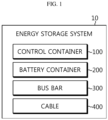
- FIG. 1 is a diagram schematically showing an energy storage system 10 according to an embodiment of the present disclosure.
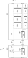
- FIG. 2 is a perspective view of an energy storage system 10 according to an embodiment of the present disclosure.
- an energy storage system 10 may include a control container 100 and a battery container 200.
- the control container 100 and the battery container 200 may be electrically and communicatively connected.
- the control container 100 may be expressed as E-LINK
- the battery container 200 may be expressed as B-LINK.
- the energy storage system 10 may further include an injection container (not shown).
- the injection container is controlled by the control container 100 and/or the battery container 200, and when a fire occurs in the battery container 200, the injection container may inject a fire extinguishing liquid (e.g., water) to the battery container 200.
- a fire extinguishing liquid e.g., water
- control container 100 may be connected to a power conversion system (PCS) to supply power to internal components of the control container 100 and the battery container 200.
- PCS power conversion system
- control container 100 may include a monitoring unit (not shown) capable of comprehensively monitoring the energy storage system 10.
- the battery container 200 may include a plurality of battery racks in which battery modules are loaded, a fire suppression unit (e.g., an air conditioning unit, a fire extinguishing unit, and a ventilation unit), and the like.
- the battery container 200 may form a power line and a communication line with the control container 100.
- the energy storage system 10 may include a control container 100 and a battery container 200. Also, since the control container 100 and the battery container 200 are connected to each other by wire, a power line and a communication line may be formed between the control container 100 and the battery container 200.
- FIG. 3 is a diagram schematically showing a control container 100 according to an embodiment of the present disclosure.
- control container 100 may include a main line 110, a main switch 120, and a main control unit 130.
- the main line 110 may be a power line included in the control container 100.
- the main line 110 may be a direct current line (DC line).
- DC line direct current line
- the main switch 120 may be configured to be connected to the main line 110.
- the main switch 120 may be connected in series to the main line 110.
- the main control unit 130 may be configured to control the operation state of the main switch 120.
- the main control unit 130 may control the operation state of the main switch 120 to a turn-on state or a turn-off state. For example, when the operation state of the main switch 120 is a turn-on state, the main line 110 may be electrically connected. Conversely, when the operation state of the main switch 120 is a turn-off state, the main line 110 may be electrically cut off.
- FIG. 4 is a diagram schematically showing a battery container 200 according to an embodiment of the present disclosure.
- FIG. 5 is a diagram schematically showing an exemplary configuration of an energy storage system 10 according to an embodiment of the present disclosure.
- the battery container 200 may include a sub line 210, a battery unit 220, a sensing unit 230, and a sub control unit 240.
- the sub line 210 may be configured to be electrically connected to the main line 110.
- the sub line 210 may be a power line, identical to the main line 110.
- the sub line 210 may be a DC line.
- the control container 100 and the battery container 200 are electrically connected, the sub line 210 may be electrically connected to the main line 110.
- the main line 110 and the sub line 210 may be electrically connected.
- the battery unit 220 may be configured to be connected to the sub line 210.
- the battery unit 220 may include a plurality of battery racks BR1 to BRn, and each battery rack BR1 to BRn may include a plurality of battery modules.
- the battery unit 220 may include a plurality of battery racks BR1 to BRn.
- the battery unit 220 may include a first battery rack BR1, a second battery rack BR2, and an n-th battery rack BRn.
- n is a natural number greater than or equal to 2, and may be determined based on various factors such as the size of the battery container 200 and the allowable capacity of the energy storage system 10.
- the sensing unit 230 may be configured to detect whether the door 260 provided in the battery container 200 is opened or closed.
- the sensing unit 230 may detect whether the door 260 provided in the battery container 200 is opened or closed.
- the sensing unit 230 may be a magnetic sensor, a piezoelectric sensor, or an optical sensor capable of detecting whether the door 260 is opened or closed.
- the sensing unit 230 may include a plurality of sensing units S1 to Sn.
- the sensing unit 230 may include a first sensing unit S1, a second sensing unit S2, and an n-th sensing unit Sn.
- the battery container 200 may be configured to have a plurality of doors 260.
- the sensing unit 230 may be configured to detect whether each of the plurality of doors 260 is opened or closed.
- the battery container 200 may include a number of doors 260 corresponding to the number of battery racks in order for a worker to perform work (e.g., maintenance) on each battery rack. That is, after opening the door 260 corresponding to the battery rack for work, the worker may proceed with the work on the corresponding battery rack.
- the battery container 200 may include the n number of doors 260 corresponding to the n number of battery racks.
- the sensing unit 230 may include the n number of sensing units S1 to Sn corresponding to the n number of doors 260.
- the sub control unit 240 may be connected to the sensing unit 230 to enable communication. Also, the sub control unit 240 may be configured to determine the opened/closed state of the door 260 based on the sensing signal received from the sensing unit 230.
- FIGS. 6 and 7 are diagrams schematically showing exemplary configurations of a sub control unit 240 and a sensing unit 230 according to an embodiment of the present disclosure.
- the sub control unit 240 may be connected to the sensing units S1 to Sn included in the sensing unit 230 to form a closed circuit.
- the sub control unit 240 may be connected to the first sensing unit S1, and the first sensing unit S1 may be connected to the second sensing unit S2.
- the n-th sensing unit Sn may be connected to the sub control unit 240. Accordingly, the closed circuit connecting the sub control unit 240, the first sensing unit S1, the second sensing unit S2, and the n-th sensing unit Sn may be formed.
- resistance elements and the like are omitted for convenience of description.
- the sensing units S1 to Sn may be magnetic sensors. That is, each of the sensing units S1 to Sn may include a first magnetic unit and a second magnetic unit.
- the operation state of the sensing unit may be a turn-off state.
- the operation state of the sensing unit may be a turn-on state.
- the operation states of the n number of sensing units S1 to Sn may all be turn-on states.
- a closed circuit connecting the sub control unit 240 and the sensing unit 230 may be electrically connected.
- the sub control unit 240 may determine the opened/closed state of the door 260 provided in the battery container 200 by detecting whether a closed circuit is connected.
- the sub control unit 240 may be configured to transmit the determined opened/closed state to the main control unit 130.
- the sub control unit 240 may transmit opened/closed state information indicating an opened state or a closed state to the main control unit 130.
- the main control unit 130 may be configured to block the connection between the main line 110 and the sub line 210 by controlling the operation state of the main switch 120 to a turn-off state. Conversely, when the door 260 is in a closed state, the main control unit 130 may be configured to connect the main line 110 and the sub line 210 by controlling the operation state of the main switch 120 to a turn-on state.
- one end of the main switch 120 may be connected to the sub line 210 through the main line 110. Also, the other end of the main switch 120 may be connected to a PCS (not shown) through the main line 110.
- the connections between the PCS and the control container 100 and the battery container 200 may be cut off. Therefore, the electrical connection between the main line 110 and the sub line 210 may be cut off.
- the PCS, the control container 100, and the battery container 200 may be electrically connected. Therefore, the main line 110 and the sub line 210 may be electrically connected.
- the main control unit 130 may be configured to control the operation state of the main switch 120 to a turn-off state, when at least one of the plurality of doors 260 is in an opened state.
- the sub control unit 240 may transmit the opened/closed state information indicating the opened state to the main control unit 130.
- the main control unit 130 may block the connection between the main line 110 and the sub line 210 by controlling the operation state of the main switch 120 to a turn-off state. Accordingly, when all doors 260 provided in the battery container 200 are closed, the operation state of the main switch 120 is controlled to a turn-on state, and the main line 110 and the sub line 210 may be electrically connected.
- the energy storage system 10 may cut off power of the battery container 200 depending on whether the door 260 provided in the battery container 200 is opened or closed. That is, even if the worker does not directly control the operation state of the main switch 120 to a turn-off state, power to the battery container 200 may be cut off at the moment the door 260 is opened. Therefore, since the battery container 200 is in an electrically safe state, the safety of workers can be enhanced. Due to this, there is an advantage in that human accidents due to carelessness of the worker can be prevented in advance.
- FIG. 8 is a diagram schematically showing an exemplary configuration of an energy storage system 10 according to another embodiment of the present disclosure.
- the battery container 200 may further include a sub switch 250.
- the sub switch 250 may be configured to be connected between the sub line 210 and the battery unit 220.
- the sub switch 250 may have one end connected to the sub line 210 and the other end connected to the battery unit 220.
- a line connected to the other end of the sub switch 250 may be connected to each of the plurality of battery racks BR1 to BRn included in the battery unit 220. That is, the sub switch 250 may be connected to a common line connecting the sub line 210 and the plurality of battery racks BR1 to BRn.
- the sub switch 250 may be connected between the sub line 210 and the battery unit 220.
- the sub line 210 and the battery unit 220 may be electrically connected or disconnected.
- the sub switch 250 may be configured such that the operation state thereof is controlled by the sub control unit 240.
- the sub control unit 240 may be configured to control the operation state of the sub switch 250 based on the determined opened/closed state. For example, the sub control unit 240 may control the operation state of the sub switch 250 to a turn-on state or a turn-off state based on the determined opened/closed state.
- the sub control unit 240 may be configured to block the connection between the sub line 210 and the battery unit 220 by controlling the operation state of the sub switch 250 to a turn-off state when the door 260 is in an opened state. Conversely, the sub control unit 240 may be configured to connect the sub line 210 and the battery unit 220 by controlling the operation state of the sub switch 250 to a turn-on state when the door 260 is in a closed state.
- the sub control unit 240 may determine whether the door 260 provided in the battery container 200 is opened or closed through the sensing unit 230, and when the door 260 is in an opened state, the sub control unit 240 may cut off the electrical connection between the sub line 210 and the battery unit 220.
- the main switch 120 included in the control container 100 and/or the sub switch 250 included in the battery container 200 can be controlled to a turn-off state to enhance the safety of workers.
- the operation state of the main switch 120 is not controlled to a turn-off state due to carelessness of the worker or malfunction, the operation state of the sub switch 250 is controlled to a turn-off state, so safety for the worker can be further enhanced.
- the energy storage system 10 may further include a bus bar 300 and a cable 400.
- the bus bar 300 may be configured to electrically connect the control container 100 and the battery container 200 by connecting one end and the other end to the main line 110 and the sub line 210, respectively.
- the bus bar 300 may be connected between the control container 100 and the battery container 200.
- one end of the bus bar 300 may be connected to the main line 110 of the control container 100, and the other end of the bus bar 300 may be connected to the sub line 210 of the battery container 200.
- a power line including the main line 110, the bus bar 300, and the sub line 210 may be formed.
- One end and the other end of the cable 400 may be connected to the main control unit 130 and the sub control unit 240, respectively, so that the main control unit 130 and the sub control unit 240 can communicate with each other.
- the cable 400 may be connected between the control container 100 and the battery container 200.
- one end of the cable 400 may be connected to the main control unit 130 of the control container 100, and the other end of the cable 400 may be connected to the sub control unit 240 of the battery container 200.
- a communication line including the main control unit 130, the cable 400, and the sub control unit 240 may be formed.
- FIG. 9 is a diagram schematically showing an exemplary configuration of an energy storage system 10 according to still another embodiment of the present disclosure.
- the battery container 200 may be provided in plurality. Specifically, when a plurality of battery container 200 is provided, the main line 110 and a plurality of sub line 210 may form one power line by connecting the sub lines 210 in series.
- a first battery container 201, a second battery container 202, and a third battery container 203 may be included in the energy storage system 10.
- the control container 100 and the plurality of battery containers 200 may be electrically connected through the bus bar 300.
- the main line 110 of the control container 100 and the sub lines 210 of the first to third battery containers 201, 202, 203 may form one power line.
- the control container 100 and the plurality of battery containers 200 may be communicatively connected through the cable 400.
- a communication line between the control container 100 and the plurality of battery containers 200 may be formed in a home-run method and a daisy chain method.
- the control container 100 may be communicatively connected to the first to third battery containers 201, 202, 203, respectively.
- the daisy chain method the control container 100 may be connected to the first battery container 201, the first battery container 201 may be connected to the second battery container 202, and the second battery container 202 may be connected to the third battery container 203.
- the energy storage system 10 includes three battery containers 200, but more battery containers 200 may be connected through a bus bar 300 and a cable 400. That is, the structure of the battery container 200 is an expandable modular structure. Accordingly, the number of battery containers 200 included in the energy storage system 10 can be easily expanded through connection members (e.g., bus bars and cables).
- the main control unit 130 may be configured to control the operation state of the main switch 120 to a turn-off state when the door 260 of at least one of the plurality of battery containers 200 is in an opened state.
- the main control unit 130 may control the operation state of the main switch 120 to a turn-off state.
- the power line formed by the control container 100 and the first to third battery containers 201, 202, 203 is released, so that the first to third battery containers 201, 202, 203 may be shut down. Therefore, the worker can safely work on the battery container 200.
- the operation state of the main switch 120 is not controlled by the main control unit 130, and the operation state of the sub switch 250 may be controlled by the sub control unit 240 in each of the plurality of battery container 200.
- the sub control unit 240 may be configured to control the operation state of the corresponding sub switch 250 to a turn-off state when the door 260 is in an opened state.
- FIG. 9 it is assumed that all of the doors 260 included in the first battery container 201 and the third battery container 203 are in a closed state, and at least one of the doors 260 included in the second battery container 202 is in an opened state.
- the sub control unit 240 included in the second battery container 202 may control the operation state of the corresponding sub switch 250 to a turn-off state.
- the electrical connections between the control container 100, the first battery container 201, and the third battery container 203 may be maintained, and only the second battery container 202 may be in a shutdown state. Accordingly, the work can safely work on the second battery container 202 without shutting down all of the plurality of battery containers 200.
- the main control unit 130 may control the operation state of the main switch 120 to a turn-off state.
- the sub control unit 240 included in the battery container 200 in which the door 260 is opened may control the operation state of the corresponding sub switch 250 to a turn-off state.
- FIG. 9 it is assumed that all of the doors 260 included in the first battery container 201 and the third battery container 203 are in a closed state, and at least one of the doors 260 included in the second battery container 202 is in an opened state.
- the main control unit 130 can control the operation state of the main switch 120 to a turn-off state.
- the sub control unit 240 included in the second battery container 202 may control the operation state of the corresponding sub switch 250 to a turn-off state. That is, since both the main switch 120 and the sub switch 250 are controlled in a turn-off state, power to the second battery container 202 can be completely cut off. Thus, safety for the worker can be further enhanced.
- the main control unit 130 and the sub control unit 240 may selectively include processors known in the art, application-specific integrated circuit (ASIC), other chipsets, logic circuits, registers, communication modems, data processing devices, and the like to execute various control logic performed in the present disclosure.
- ASIC application-specific integrated circuit
- the main control unit 130 and the sub control unit 240 may be implemented as a set of program modules.
- the program module may be stored in a memory (not shown) and executed by the main control unit 130 and the sub control unit 240.
- the memory is not particularly limited in its type as long as it is a known information storage means that can record, erase, update and read data.
- the information storage means may include RAM, flash memory, ROM, EEPROM, registers, and the like.
Landscapes
- Chemical & Material Sciences (AREA)
- Chemical Kinetics & Catalysis (AREA)
- Electrochemistry (AREA)
- General Chemical & Material Sciences (AREA)
- Engineering & Computer Science (AREA)
- Manufacturing & Machinery (AREA)
- Microelectronics & Electronic Packaging (AREA)
- Battery Mounting, Suspending (AREA)
- Charge And Discharge Circuits For Batteries Or The Like (AREA)
- Protection Of Static Devices (AREA)
Abstract
Description
- The present application claims priority to
Korean Patent Application No. 10-2022-0055929 filed on May 6, 2022 - The present disclosure relates to an energy storage system (ESS), and more particularly, to an energy storage system with enhanced safety.
- Recently, the demand for portable electronic products such as notebook computers, video cameras and portable telephones has increased sharply, and electric vehicles, energy storage batteries, robots, satellites and the like have been developed in earnest. Accordingly, high-performance batteries allowing repeated charging and discharging are being actively studied.
- Batteries commercially available at present include nickel-cadmium batteries, nickel hydrogen batteries, nickel-zinc batteries, lithium batteries and the like. Among them, the lithium batteries are in the limelight since they have almost no memory effect compared to nickel-based batteries and also have very low self-charging rate and high energy density.
- An energy storage system using such a battery may be a device that stores a large amount of power and provides the stored power to a plurality of load facilities. For example, an energy storage system is used in the form of an industrial, building, or household energy management system, and is used as a regular power grid and/or an emergency power grid by providing stored power to load facilities at each point of use.
- Conventionally, maintenance work was performed after a worker cut off power by manipulating the cut-off switch of the energy storage system. In this maintenance process, there is a problem that human injury may occur due to the operator's negligence or malfunction of the cut-off switch. Therefore, in order to improve the safety of workers, a technology capable of automatically controlling the shut-off switch in a maintenance situation is required.
- The present disclosure is designed to solve the problems of the related art, and therefore the present disclosure is directed to providing an energy storage system with enhanced safety, which may control a shut-off switch for the safety of workers.
- These and other objects and advantages of the present disclosure may be understood from the following detailed description and will become more fully apparent from the exemplary embodiments of the present disclosure. Also, it will be easily understood that the objects and advantages of the present disclosure may be realized by the means shown in the appended claims and combinations thereof.
- An energy storage system with enhanced safety according to one aspect of the present disclosure may include a control container and a battery container.
- The control container may include a main line; a main switch configured to be connected to the main line; and a main control unit configured to control the operation state of the main switch.
- The battery container may include a sub line configured to be electrically connected with the main line; a battery unit configured to be connected to the sub line; a sensing unit configured to detect whether a provided door is opened or closed; and a sub control unit configured to determine an opened/closed state of the door based on a sensing signal received from the sensing unit and transmit the determined opened/closed state to the main control unit.
- The main control unit may be configured to block the connection between the main line and the sub line by controlling the operation state of the main switch to a turn-off state, when the door is in the opened state.
- The main control unit may be configured to connect the main line and the sub line by controlling the operation state of the main switch to a turn-on state, when the door is in the closed state.
- The battery container may be configured to have a plurality of doors.
- The sensing unit may be configured to detect whether each of the plurality of doors is opened or closed.
- The main control unit may be configured to control the operation state of the main switch to a turn-off state, when at least one of the plurality of doors is in the opened state.
- When the battery container is provided in plurality, the main line and a plurality of sub lines may be configured to form one power line by connecting the sub lines in series.
- The main control unit may be configured to control the operation state of the main switch to a turn-off state, when the door of at least one of the plurality of battery containers is in an opened state.
- The battery container may further include a sub switch connected between the sub line and the battery unit and configured such that the operation state thereof is controlled by the sub control unit.
- The sub control unit may be configured to control the operation state of the sub switch based on the determined opened/closed state.
- The sub control unit may be configured to block the connection between the sub line and the battery unit by controlling the operation state of the sub switch to a turn-off state, when the door is in the opened state.
- The sub control unit may be configured to connect the sub line and the battery unit by controlling the operation state of the sub switch to a turn-on state, when the door is in the closed state.
- An energy storage system with enhanced safety according to another aspect of the present disclosure may further comprise a bus bar having one end and the other end connected to the main line and the sub line, respectively, and configured to electrically connect the control container and the battery container.
- An energy storage system with enhanced safety according to another aspect of the present disclosure may further comprise a cable having one end and the other end connected to the main control unit and the sub control unit, respectively, and configured to connect the main control unit and the sub control unit so that communication is possible.
- According to one aspect of the present disclosure, since the battery container can be shut down depending on whether a door included in the battery container is opened, there is an advantage in inducing a worker to safely work on the battery container.
- The effects of the present disclosure are not limited to the effects mentioned above, and other effects not mentioned will be clearly understood by those skilled in the art from the description of the claims.
- The accompanying drawings illustrate a preferred embodiment of the present disclosure and together with the foregoing disclosure, serve to provide further understanding of the technical features of the present disclosure, and thus, the present disclosure is not construed as being limited to the drawing.
-
FIG. 1 is a diagram schematically showing an energy storage system according to an embodiment of the present disclosure. -
FIG. 2 is a perspective view of an energy storage system according to an embodiment of the present disclosure. -
FIG. 3 is a diagram schematically showing a control container according to an embodiment of the present disclosure. -
FIG. 4 is a diagram schematically showing a battery container according to an embodiment of the present disclosure. -
FIG. 5 is a diagram schematically showing an exemplary configuration of an energy storage system according to an embodiment of the present disclosure. -
FIGS. 6 and 7 are diagrams schematically showing exemplary configurations of a sub control unit and a sensing unit according to an embodiment of the present disclosure. -
FIG. 8 is a diagram schematically showing an exemplary configuration of an energy storage system according to another embodiment of the present disclosure. -
FIG. 9 is a diagram schematically showing an exemplary configuration of an energy storage system according to still another embodiment of the present disclosure. - It should be understood that the terms used in the specification and the appended claims should not be construed as limited to general and dictionary meanings, but interpreted based on the meanings and concepts corresponding to technical aspects of the present disclosure on the basis of the principle that the inventor is allowed to define terms appropriately for the best explanation.
- Therefore, the description proposed herein is just a preferable example for the purpose of illustrations only, not intended to limit the scope of the disclosure, so it should be understood that other equivalents and modifications could be made thereto without departing from the scope of the disclosure.
- Additionally, in describing the present disclosure, when it is deemed that a detailed description of relevant known elements or functions renders the key subject matter of the present disclosure ambiguous, the detailed description is omitted herein.
- The terms including the ordinal number such as "first", "second" and the like, may be used to distinguish one element from another among various elements, but not intended to limit the elements by the terms.
- Throughout the specification, when a portion is referred to as "comprising" or "including" any element, it means that the portion may include other elements further, without excluding other elements, unless specifically stated otherwise.
- In addition, throughout the specification, when a portion is referred to as being "connected" to another portion, it is not limited to the case that they are "directly connected", but it also includes the case where they are "indirectly connected" with another element being interposed between them.
- Hereinafter, preferred embodiments of the present disclosure will be described in detail with reference to the accompanying drawings.
-
FIG. 1 is a diagram schematically showing anenergy storage system 10 according to an embodiment of the present disclosure.FIG. 2 is a perspective view of anenergy storage system 10 according to an embodiment of the present disclosure. - Referring to
FIG. 1 , anenergy storage system 10 may include acontrol container 100 and abattery container 200. - The
control container 100 and thebattery container 200 may be electrically and communicatively connected. Thecontrol container 100 may be expressed as E-LINK, and thebattery container 200 may be expressed as B-LINK. - In addition, the
energy storage system 10 may further include an injection container (not shown). The injection container is controlled by thecontrol container 100 and/or thebattery container 200, and when a fire occurs in thebattery container 200, the injection container may inject a fire extinguishing liquid (e.g., water) to thebattery container 200. - Specifically, the
control container 100 may be connected to a power conversion system (PCS) to supply power to internal components of thecontrol container 100 and thebattery container 200. In addition, thecontrol container 100 may include a monitoring unit (not shown) capable of comprehensively monitoring theenergy storage system 10. - The
battery container 200 may include a plurality of battery racks in which battery modules are loaded, a fire suppression unit (e.g., an air conditioning unit, a fire extinguishing unit, and a ventilation unit), and the like. Thebattery container 200 may form a power line and a communication line with thecontrol container 100. - For example, in the embodiment of
FIG. 2 , theenergy storage system 10 may include acontrol container 100 and abattery container 200. Also, since thecontrol container 100 and thebattery container 200 are connected to each other by wire, a power line and a communication line may be formed between thecontrol container 100 and thebattery container 200. -
FIG. 3 is a diagram schematically showing acontrol container 100 according to an embodiment of the present disclosure. - Referring to
FIG. 3 , thecontrol container 100 may include amain line 110, amain switch 120, and amain control unit 130. - The
main line 110 may be a power line included in thecontrol container 100. For example, themain line 110 may be a direct current line (DC line). - The
main switch 120 may be configured to be connected to themain line 110. For example, themain switch 120 may be connected in series to themain line 110. - The
main control unit 130 may be configured to control the operation state of themain switch 120. - Specifically, the
main control unit 130 may control the operation state of themain switch 120 to a turn-on state or a turn-off state. For example, when the operation state of themain switch 120 is a turn-on state, themain line 110 may be electrically connected. Conversely, when the operation state of themain switch 120 is a turn-off state, themain line 110 may be electrically cut off. -
FIG. 4 is a diagram schematically showing abattery container 200 according to an embodiment of the present disclosure.FIG. 5 is a diagram schematically showing an exemplary configuration of anenergy storage system 10 according to an embodiment of the present disclosure. - Referring to
FIG. 4 , thebattery container 200 may include asub line 210, abattery unit 220, asensing unit 230, and asub control unit 240. - The
sub line 210 may be configured to be electrically connected to themain line 110. - Specifically, the
sub line 210 may be a power line, identical to themain line 110. For example, like themain line 110, thesub line 210 may be a DC line. As thecontrol container 100 and thebattery container 200 are electrically connected, thesub line 210 may be electrically connected to themain line 110. - For example, in the embodiment of
FIG. 5 , themain line 110 and thesub line 210 may be electrically connected. - The
battery unit 220 may be configured to be connected to thesub line 210. Specifically, thebattery unit 220 may include a plurality of battery racks BR1 to BRn, and each battery rack BR1 to BRn may include a plurality of battery modules. - For example, the
battery unit 220 may include a plurality of battery racks BR1 to BRn. In the embodiment ofFIG. 5 , thebattery unit 220 may include a first battery rack BR1, a second battery rack BR2, and an n-th battery rack BRn. Here, n is a natural number greater than or equal to 2, and may be determined based on various factors such as the size of thebattery container 200 and the allowable capacity of theenergy storage system 10. - The
sensing unit 230 may be configured to detect whether thedoor 260 provided in thebattery container 200 is opened or closed. - Specifically, the
sensing unit 230 may detect whether thedoor 260 provided in thebattery container 200 is opened or closed. For example, thesensing unit 230 may be a magnetic sensor, a piezoelectric sensor, or an optical sensor capable of detecting whether thedoor 260 is opened or closed. - For example, the
sensing unit 230 may include a plurality of sensing units S1 to Sn. In the embodiment ofFIG. 5 , thesensing unit 230 may include a first sensing unit S1, a second sensing unit S2, and an n-th sensing unit Sn. - Preferably, the
battery container 200 may be configured to have a plurality ofdoors 260. Also, thesensing unit 230 may be configured to detect whether each of the plurality ofdoors 260 is opened or closed. In general, thebattery container 200 may include a number ofdoors 260 corresponding to the number of battery racks in order for a worker to perform work (e.g., maintenance) on each battery rack. That is, after opening thedoor 260 corresponding to the battery rack for work, the worker may proceed with the work on the corresponding battery rack. Accordingly, in the embodiment ofFIG. 5 , thebattery container 200 may include the n number ofdoors 260 corresponding to the n number of battery racks. Also, thesensing unit 230 may include the n number of sensing units S1 to Sn corresponding to the n number ofdoors 260. - The
sub control unit 240 may be connected to thesensing unit 230 to enable communication. Also, thesub control unit 240 may be configured to determine the opened/closed state of thedoor 260 based on the sensing signal received from thesensing unit 230. -
FIGS. 6 and 7 are diagrams schematically showing exemplary configurations of asub control unit 240 and asensing unit 230 according to an embodiment of the present disclosure. - The
sub control unit 240 may be connected to the sensing units S1 to Sn included in thesensing unit 230 to form a closed circuit. For example, in the embodiment ofFIG. 6 , thesub control unit 240 may be connected to the first sensing unit S1, and the first sensing unit S1 may be connected to the second sensing unit S2. Also, the n-th sensing unit Sn may be connected to thesub control unit 240. Accordingly, the closed circuit connecting thesub control unit 240, the first sensing unit S1, the second sensing unit S2, and the n-th sensing unit Sn may be formed. However, it should be noted that in the closed circuit ofFIG. 6 , resistance elements and the like are omitted for convenience of description. - For example, the sensing units S1 to Sn may be magnetic sensors. That is, each of the sensing units S1 to Sn may include a first magnetic unit and a second magnetic unit. When the
door 260 is open, since the first magnetic unit and the second magnetic unit are separated, the operation state of the sensing unit may be a turn-off state. Conversely, when thedoor 260 is closed, since the first magnetic unit and the second magnetic unit are connected, the operation state of the sensing unit may be a turn-on state. - Referring to
FIG. 7 , when all of the n number ofdoors 260 are closed, the operation states of the n number of sensing units S1 to Sn may all be turn-on states. In this case, a closed circuit connecting thesub control unit 240 and thesensing unit 230 may be electrically connected. Accordingly, thesub control unit 240 may determine the opened/closed state of thedoor 260 provided in thebattery container 200 by detecting whether a closed circuit is connected. - The
sub control unit 240 may be configured to transmit the determined opened/closed state to themain control unit 130. - Specifically, the
sub control unit 240 may transmit opened/closed state information indicating an opened state or a closed state to themain control unit 130. - When the
door 260 is in an opened state, themain control unit 130 may be configured to block the connection between themain line 110 and thesub line 210 by controlling the operation state of themain switch 120 to a turn-off state. Conversely, when thedoor 260 is in a closed state, themain control unit 130 may be configured to connect themain line 110 and thesub line 210 by controlling the operation state of themain switch 120 to a turn-on state. - Specifically, one end of the
main switch 120 may be connected to thesub line 210 through themain line 110. Also, the other end of themain switch 120 may be connected to a PCS (not shown) through themain line 110. - For example, when the operation state of the
main switch 120 is controlled to a turn-off state, the connections between the PCS and thecontrol container 100 and thebattery container 200 may be cut off. Therefore, the electrical connection between themain line 110 and thesub line 210 may be cut off. - As another example, when the operation state of the
main switch 120 is controlled as a turn-on state, the PCS, thecontrol container 100, and thebattery container 200 may be electrically connected. Therefore, themain line 110 and thesub line 210 may be electrically connected. - In particular, the
main control unit 130 may be configured to control the operation state of themain switch 120 to a turn-off state, when at least one of the plurality ofdoors 260 is in an opened state. - Specifically, when at least one
door 260 of the plurality ofdoors 260 included in thebattery container 200 is open, thesub control unit 240 may transmit the opened/closed state information indicating the opened state to themain control unit 130. Upon receiving the opened/closed state information indicating the opened state, themain control unit 130 may block the connection between themain line 110 and thesub line 210 by controlling the operation state of themain switch 120 to a turn-off state. Accordingly, when alldoors 260 provided in thebattery container 200 are closed, the operation state of themain switch 120 is controlled to a turn-on state, and themain line 110 and thesub line 210 may be electrically connected. - The
energy storage system 10 according to an embodiment of the present disclosure may cut off power of thebattery container 200 depending on whether thedoor 260 provided in thebattery container 200 is opened or closed. That is, even if the worker does not directly control the operation state of themain switch 120 to a turn-off state, power to thebattery container 200 may be cut off at the moment thedoor 260 is opened. Therefore, since thebattery container 200 is in an electrically safe state, the safety of workers can be enhanced. Due to this, there is an advantage in that human accidents due to carelessness of the worker can be prevented in advance. -
FIG. 8 is a diagram schematically showing an exemplary configuration of anenergy storage system 10 according to another embodiment of the present disclosure. - Referring to
FIGS. 1 and8 , thebattery container 200 may further include asub switch 250. - The
sub switch 250 may be configured to be connected between thesub line 210 and thebattery unit 220. - Specifically, the
sub switch 250 may have one end connected to thesub line 210 and the other end connected to thebattery unit 220. A line connected to the other end of thesub switch 250 may be connected to each of the plurality of battery racks BR1 to BRn included in thebattery unit 220. That is, thesub switch 250 may be connected to a common line connecting thesub line 210 and the plurality of battery racks BR1 to BRn. - For example, in the embodiment of
FIG. 8 , thesub switch 250 may be connected between thesub line 210 and thebattery unit 220. Depending on the operation state of thesub switch 250, thesub line 210 and thebattery unit 220 may be electrically connected or disconnected. - The
sub switch 250 may be configured such that the operation state thereof is controlled by thesub control unit 240. - Specifically, the
sub control unit 240 may be configured to control the operation state of thesub switch 250 based on the determined opened/closed state. For example, thesub control unit 240 may control the operation state of thesub switch 250 to a turn-on state or a turn-off state based on the determined opened/closed state. - For example, the
sub control unit 240 may be configured to block the connection between thesub line 210 and thebattery unit 220 by controlling the operation state of thesub switch 250 to a turn-off state when thedoor 260 is in an opened state. Conversely, thesub control unit 240 may be configured to connect thesub line 210 and thebattery unit 220 by controlling the operation state of thesub switch 250 to a turn-on state when thedoor 260 is in a closed state. - That is, the
sub control unit 240 may determine whether thedoor 260 provided in thebattery container 200 is opened or closed through thesensing unit 230, and when thedoor 260 is in an opened state, thesub control unit 240 may cut off the electrical connection between thesub line 210 and thebattery unit 220. - In the
energy storage system 10 according to an embodiment of the present disclosure, when thedoor 260 of thebattery container 200 is opened, themain switch 120 included in thecontrol container 100 and/or thesub switch 250 included in thebattery container 200 can be controlled to a turn-off state to enhance the safety of workers. - In particular, even if the operation state of the
main switch 120 is not controlled to a turn-off state due to carelessness of the worker or malfunction, the operation state of thesub switch 250 is controlled to a turn-off state, so safety for the worker can be further enhanced. - Further referring to
FIG. 1 , theenergy storage system 10 may further include abus bar 300 and acable 400. - The
bus bar 300 may be configured to electrically connect thecontrol container 100 and thebattery container 200 by connecting one end and the other end to themain line 110 and thesub line 210, respectively. - For example, in the embodiments of
FIGS. 2 ,5 and8 , thebus bar 300 may be connected between thecontrol container 100 and thebattery container 200. In particular, one end of thebus bar 300 may be connected to themain line 110 of thecontrol container 100, and the other end of thebus bar 300 may be connected to thesub line 210 of thebattery container 200. Accordingly, a power line including themain line 110, thebus bar 300, and thesub line 210 may be formed. - One end and the other end of the
cable 400 may be connected to themain control unit 130 and thesub control unit 240, respectively, so that themain control unit 130 and thesub control unit 240 can communicate with each other. - For example, in the embodiments of
FIGS. 2 ,5 and8 , thecable 400 may be connected between thecontrol container 100 and thebattery container 200. In particular, one end of thecable 400 may be connected to themain control unit 130 of thecontrol container 100, and the other end of thecable 400 may be connected to thesub control unit 240 of thebattery container 200. Accordingly, a communication line including themain control unit 130, thecable 400, and thesub control unit 240 may be formed. -
FIG. 9 is a diagram schematically showing an exemplary configuration of anenergy storage system 10 according to still another embodiment of the present disclosure. - The
battery container 200 may be provided in plurality. Specifically, when a plurality ofbattery container 200 is provided, themain line 110 and a plurality ofsub line 210 may form one power line by connecting thesub lines 210 in series. - In the embodiment of
FIG. 9 , afirst battery container 201, asecond battery container 202, and athird battery container 203 may be included in theenergy storage system 10. Thecontrol container 100 and the plurality ofbattery containers 200 may be electrically connected through thebus bar 300. For example, themain line 110 of thecontrol container 100 and thesub lines 210 of the first tothird battery containers - Also, in the embodiment of
FIG. 9 , thecontrol container 100 and the plurality ofbattery containers 200 may be communicatively connected through thecable 400. Preferably, a communication line between thecontrol container 100 and the plurality ofbattery containers 200 may be formed in a home-run method and a daisy chain method. For example, according to the home-run method, thecontrol container 100 may be communicatively connected to the first tothird battery containers control container 100 may be connected to thefirst battery container 201, thefirst battery container 201 may be connected to thesecond battery container 202, and thesecond battery container 202 may be connected to thethird battery container 203. - In the embodiment of
FIG. 9 , it has been described that theenergy storage system 10 includes threebattery containers 200, butmore battery containers 200 may be connected through abus bar 300 and acable 400. That is, the structure of thebattery container 200 is an expandable modular structure. Accordingly, the number ofbattery containers 200 included in theenergy storage system 10 can be easily expanded through connection members (e.g., bus bars and cables). - For example, the
main control unit 130 may be configured to control the operation state of themain switch 120 to a turn-off state when thedoor 260 of at least one of the plurality ofbattery containers 200 is in an opened state. In the embodiment ofFIG. 9 , when at least one of alldoors 260 included in the first tothird battery containers main control unit 130 may control the operation state of themain switch 120 to a turn-off state. In this case, the power line formed by thecontrol container 100 and the first tothird battery containers third battery containers battery container 200. - As another example, when the
door 260 of at least one of the plurality ofbattery container 200 is in the opened state, the operation state of themain switch 120 is not controlled by themain control unit 130, and the operation state of thesub switch 250 may be controlled by thesub control unit 240 in each of the plurality ofbattery container 200. Thesub control unit 240 may be configured to control the operation state of thecorresponding sub switch 250 to a turn-off state when thedoor 260 is in an opened state. In the embodiment ofFIG. 9 , it is assumed that all of thedoors 260 included in thefirst battery container 201 and thethird battery container 203 are in a closed state, and at least one of thedoors 260 included in thesecond battery container 202 is in an opened state. Thesub control unit 240 included in thesecond battery container 202 may control the operation state of thecorresponding sub switch 250 to a turn-off state. In this case, the electrical connections between thecontrol container 100, thefirst battery container 201, and thethird battery container 203 may be maintained, and only thesecond battery container 202 may be in a shutdown state. Accordingly, the work can safely work on thesecond battery container 202 without shutting down all of the plurality ofbattery containers 200. - As still another example, when the
door 260 of at least one of the plurality ofbattery containers 200 is in an opened state, themain control unit 130 may control the operation state of themain switch 120 to a turn-off state. In addition, thesub control unit 240 included in thebattery container 200 in which thedoor 260 is opened may control the operation state of thecorresponding sub switch 250 to a turn-off state. As in the previous embodiment, in the embodiment ofFIG. 9 , it is assumed that all of thedoors 260 included in thefirst battery container 201 and thethird battery container 203 are in a closed state, and at least one of thedoors 260 included in thesecond battery container 202 is in an opened state. Since at least onedoor 260 among thedoors 260 included in the plurality ofbattery containers 200 is open, themain control unit 130 can control the operation state of themain switch 120 to a turn-off state. In addition, thesub control unit 240 included in thesecond battery container 202 may control the operation state of thecorresponding sub switch 250 to a turn-off state. That is, since both themain switch 120 and thesub switch 250 are controlled in a turn-off state, power to thesecond battery container 202 can be completely cut off. Thus, safety for the worker can be further enhanced. - Meanwhile, the
main control unit 130 and thesub control unit 240 may selectively include processors known in the art, application-specific integrated circuit (ASIC), other chipsets, logic circuits, registers, communication modems, data processing devices, and the like to execute various control logic performed in the present disclosure. Also, when the control logic is implemented in software, themain control unit 130 and thesub control unit 240 may be implemented as a set of program modules. At this time, the program module may be stored in a memory (not shown) and executed by themain control unit 130 and thesub control unit 240. Here, the memory is not particularly limited in its type as long as it is a known information storage means that can record, erase, update and read data. As an example, the information storage means may include RAM, flash memory, ROM, EEPROM, registers, and the like. - The present disclosure has been described in detail. However, it should be understood that the detailed description and specific examples, while indicating preferred embodiments of the disclosure, are given by way of illustration only, since various changes and modifications within the scope of the disclosure will become apparent to those skilled in the art from this detailed description.
- Additionally, many substitutions, modifications and changes may be made to the present disclosure described hereinabove by those skilled in the art without departing from the technical aspects of the present disclosure, and the present disclosure is not limited to the above-described embodiments and the accompanying drawings, and each embodiment may be selectively combined in part or in whole to allow various modifications.
-
- 10: energy storage system
- 100: control container
- 110: main line
- 120: main switch
- 130: main control unit
- 200: battery container
- 210: sub line
- 220: battery unit
- 230: sensing unit
- 240: sub control unit
- 250: sub switch
- 260: door
- 300: bus bar
- 400: cable
Claims (10)
- An energy storage system with enhanced safety, comprising:a control container including a main line; a main switch configured to be connected to the main line; and a main control unit configured to control the operation state of the main switch; anda battery container including a sub line configured to be electrically connected with the main line; a battery unit configured to be connected to the sub line; a sensing unit configured to detect whether a provided door is opened or closed; and a sub control unit configured to determine an opened/closed state of the door based on a sensing signal received from the sensing unit and transmit the determined opened/closed state to the main control unit.
- The energy storage system with enhanced safety according to claim 1,
wherein the main control unit is configured to:block the connection between the main line and the sub line by controlling the operation state of the main switch to a turn-off state, when the door is in the opened state, andconnect the main line and the sub line by controlling the operation state of the main switch to a turn-on state, when the door is in the closed state. - The energy storage system with enhanced safety according to claim 2,wherein the battery container is configured to have a plurality of doors, andwherein the sensing unit is configured to detect whether each of the plurality of doors is opened or closed.
- The energy storage system with enhanced safety according to claim 3,
wherein the main control unit is configured to control the operation state of the main switch to a turn-off state, when at least one of the plurality of doors is in the opened state. - The energy storage system with enhanced safety according to claim 2,wherein when the battery container is provided in plurality, the main line and a plurality of sub lines are configured to form one power line by connecting the sub lines in series, andwherein the main control unit is configured to control the operation state of the main switch to a turn-off state, when the door of at least one of the plurality of battery containers is in an opened state.
- The energy storage system with enhanced safety according to any one of claims 1 to 5,
wherein the battery container further includes a sub switch connected between the sub line and the battery unit and configured such that the operation state thereof is controlled by the sub control unit. - The energy storage system with enhanced safety according to claim 6,
wherein the sub control unit is configured to control the operation state of the sub switch based on the determined opened/closed state. - The energy storage system with enhanced safety according to claim 7,
wherein the sub control unit is configured to:block the connection between the sub line and the battery unit by controlling the operation state of the sub switch to a turn-off state, when the door is in the opened state, andconnect the sub line and the battery unit by controlling the operation state of the sub switch to a turn-on state, when the door is in the closed state. - The energy storage system with enhanced safety according to claim 1, further comprising:
a bus bar having one end and the other end connected to the main line and the sub line, respectively, and configured to electrically connect the control container and the battery container. - The energy storage system with enhanced safety according to claim 1, further comprising:
a cable having one end and the other end connected to the main control unit and the sub control unit, respectively, and configured to connect the main control unit and the sub control unit so that communication is possible.
Applications Claiming Priority (2)
| Application Number | Priority Date | Filing Date | Title |
|---|---|---|---|
| KR1020220055929A KR20230156494A (en) | 2022-05-06 | 2022-05-06 | Energy storage system with enhanced safety |
| PCT/KR2023/006222 WO2023214862A1 (en) | 2022-05-06 | 2023-05-08 | Energy storage system with enhanced safety |
Publications (2)
| Publication Number | Publication Date |
|---|---|
| EP4475266A1 true EP4475266A1 (en) | 2024-12-11 |
| EP4475266A4 EP4475266A4 (en) | 2025-04-09 |
Family
ID=88646747
Family Applications (1)
| Application Number | Title | Priority Date | Filing Date |
|---|---|---|---|
| EP23799743.2A Pending EP4475266A4 (en) | 2022-05-06 | 2023-05-08 | Energy storage system with enhanced safety |
Country Status (7)
| Country | Link |
|---|---|
| US (1) | US20250357648A1 (en) |
| EP (1) | EP4475266A4 (en) |
| JP (1) | JP7721815B2 (en) |
| KR (1) | KR20230156494A (en) |
| CN (1) | CN118525405A (en) |
| AU (1) | AU2023263908A1 (en) |
| WO (1) | WO2023214862A1 (en) |
Family Cites Families (8)
| Publication number | Priority date | Publication date | Assignee | Title |
|---|---|---|---|---|
| KR20050012909A (en) * | 2003-07-25 | 2005-02-02 | 주식회사 포스코 | Transformer having safety device |
| WO2012158185A1 (en) * | 2011-05-13 | 2012-11-22 | Enerdel, Inc. | Energy storage system |
| KR102035031B1 (en) * | 2013-01-23 | 2019-10-23 | 에스케이이노베이션 주식회사 | Apparatus and method for door opening protection of energy storage system |
| KR102151593B1 (en) * | 2014-03-17 | 2020-09-03 | 엘에스일렉트릭(주) | Security apparatus for energy storage system |
| KR101987323B1 (en) * | 2017-08-21 | 2019-06-11 | 주식회사 케이디파워 | Enclosure for ESS having Arc Outfall |
| KR20190048081A (en) * | 2017-10-30 | 2019-05-09 | 엘에스산전 주식회사 | Integrated power conversion and grid connection system |
| KR20190063889A (en) * | 2017-11-30 | 2019-06-10 | 주식회사 대경산전 | System for controling DC distribution board of ESS |
| KR20220055929A (en) | 2020-10-27 | 2022-05-04 | 황성국 | A Low Frequency Apparatus for Stimulating an Arm or a Leg |
-
2022
- 2022-05-06 KR KR1020220055929A patent/KR20230156494A/en active Pending
-
2023
- 2023-05-08 CN CN202380017499.4A patent/CN118525405A/en active Pending
- 2023-05-08 US US18/861,001 patent/US20250357648A1/en active Pending
- 2023-05-08 EP EP23799743.2A patent/EP4475266A4/en active Pending
- 2023-05-08 WO PCT/KR2023/006222 patent/WO2023214862A1/en not_active Ceased
- 2023-05-08 AU AU2023263908A patent/AU2023263908A1/en active Pending
- 2023-05-08 JP JP2024540619A patent/JP7721815B2/en active Active
Also Published As
| Publication number | Publication date |
|---|---|
| JP7721815B2 (en) | 2025-08-12 |
| JP2025503582A (en) | 2025-02-04 |
| AU2023263908A1 (en) | 2024-11-07 |
| US20250357648A1 (en) | 2025-11-20 |
| KR20230156494A (en) | 2023-11-14 |
| WO2023214862A1 (en) | 2023-11-09 |
| EP4475266A4 (en) | 2025-04-09 |
| CN118525405A (en) | 2024-08-20 |
Similar Documents
| Publication | Publication Date | Title |
|---|---|---|
| US20230163371A1 (en) | Battery system | |
| EP3282541B1 (en) | Distributed battery management system | |
| CN103414224B (en) | A kind of high-tension integrated battery group system of Large Copacity and control method thereof | |
| US10272795B2 (en) | Electronic control device for controlling a vehicle battery pack and system employing such a device | |
| WO2003069717A3 (en) | Systems and methods for connecting battery cells background | |
| KR102690292B1 (en) | Energy storage system | |
| KR102610269B1 (en) | Power supply circuit, and battery pack including the same | |
| US20250226675A1 (en) | Energy storage system and protection unit | |
| CN110466387B (en) | An integrated power battery management system | |
| US20250357648A1 (en) | Energy storage system with enhanced safety | |
| KR20180026948A (en) | Power suplly circuit, and battery pack including the same | |
| US20160003915A1 (en) | Battery monitor system | |
| US9748798B2 (en) | Control module for an electrical energy accumulator, energy accumulator unit having such a control module, uninterruptible power supply unit and method for operating a control module | |
| CN115313314B (en) | Battery pack control method, electronic device, and computer-readable storage medium | |
| US20210119267A1 (en) | Battery pack | |
| EP3779482B1 (en) | Switch control apparatus and method | |
| EP3667850A1 (en) | Electrical system for vehicles having overvoltage protection | |
| Yıldız | Battery management system architectures for unmanned air vehicles: A strategic issue | |
| EP4380114B1 (en) | Energy storage system | |
| CN210489530U (en) | Battery relay control circuit and vehicle | |
| GB2277814A (en) | Fault tolerant programmable logic controller | |
| CN112701746A (en) | Battery equalization control method and device, storage medium and electronic device | |
| EP4503375A1 (en) | Power supply control device and method for controlling same | |
| CN118842145A (en) | Battery overcharge protection system | |
| CN112564223B (en) | Charge-discharge control device |
Legal Events
| Date | Code | Title | Description |
|---|---|---|---|
| STAA | Information on the status of an ep patent application or granted ep patent |
Free format text: STATUS: THE INTERNATIONAL PUBLICATION HAS BEEN MADE |
|
| PUAI | Public reference made under article 153(3) epc to a published international application that has entered the european phase |
Free format text: ORIGINAL CODE: 0009012 |
|
| STAA | Information on the status of an ep patent application or granted ep patent |
Free format text: STATUS: REQUEST FOR EXAMINATION WAS MADE |
|
| 17P | Request for examination filed |
Effective date: 20240904 |
|
| AK | Designated contracting states |
Kind code of ref document: A1 Designated state(s): AL AT BE BG CH CY CZ DE DK EE ES FI FR GB GR HR HU IE IS IT LI LT LU LV MC ME MK MT NL NO PL PT RO RS SE SI SK SM TR |
|
| A4 | Supplementary search report drawn up and despatched |
Effective date: 20250311 |
|
| RIC1 | Information provided on ipc code assigned before grant |
Ipc: H01M 50/251 20210101ALI20250305BHEP Ipc: H01M 50/574 20210101ALI20250305BHEP Ipc: H01M 50/502 20210101ALI20250305BHEP Ipc: H01M 10/48 20060101ALI20250305BHEP Ipc: H01M 10/42 20060101AFI20250305BHEP |
|
| DAV | Request for validation of the european patent (deleted) | ||
| DAX | Request for extension of the european patent (deleted) | ||
| STAA | Information on the status of an ep patent application or granted ep patent |
Free format text: STATUS: EXAMINATION IS IN PROGRESS |
|
| 17Q | First examination report despatched |
Effective date: 20251124 |