EP4475202A1 - Moisture-supplying device of electrode-drying apparatus - Google Patents
Moisture-supplying device of electrode-drying apparatus Download PDFInfo
- Publication number
- EP4475202A1 EP4475202A1 EP23863478.6A EP23863478A EP4475202A1 EP 4475202 A1 EP4475202 A1 EP 4475202A1 EP 23863478 A EP23863478 A EP 23863478A EP 4475202 A1 EP4475202 A1 EP 4475202A1
- Authority
- EP
- European Patent Office
- Prior art keywords
- water
- moisture
- electrode
- spray nozzle
- pump
- Prior art date
- Legal status (The legal status is an assumption and is not a legal conclusion. Google has not performed a legal analysis and makes no representation as to the accuracy of the status listed.)
- Pending
Links
Images




Classifications
-
- F—MECHANICAL ENGINEERING; LIGHTING; HEATING; WEAPONS; BLASTING
- F26—DRYING
- F26B—DRYING SOLID MATERIALS OR OBJECTS BY REMOVING LIQUID THEREFROM
- F26B21/00—Arrangements for supplying or controlling air or other gases for drying solid materials or objects
- F26B21/30—Controlling, e.g. regulating, parameters of gas supply
- F26B21/33—Humidity
-
- H—ELECTRICITY
- H01—ELECTRIC ELEMENTS
- H01M—PROCESSES OR MEANS, e.g. BATTERIES, FOR THE DIRECT CONVERSION OF CHEMICAL ENERGY INTO ELECTRICAL ENERGY
- H01M4/00—Electrodes
- H01M4/02—Electrodes composed of, or comprising, active material
- H01M4/04—Processes of manufacture in general
-
- B—PERFORMING OPERATIONS; TRANSPORTING
- B05—SPRAYING OR ATOMISING IN GENERAL; APPLYING FLUENT MATERIALS TO SURFACES, IN GENERAL
- B05B—SPRAYING APPARATUS; ATOMISING APPARATUS; NOZZLES
- B05B1/00—Nozzles, spray heads or other outlets, with or without auxiliary devices such as valves, heating means
- B05B1/30—Nozzles, spray heads or other outlets, with or without auxiliary devices such as valves, heating means designed to control volume of flow, e.g. with adjustable passages
-
- B—PERFORMING OPERATIONS; TRANSPORTING
- B05—SPRAYING OR ATOMISING IN GENERAL; APPLYING FLUENT MATERIALS TO SURFACES, IN GENERAL
- B05B—SPRAYING APPARATUS; ATOMISING APPARATUS; NOZZLES
- B05B12/00—Arrangements for controlling delivery; Arrangements for controlling the spray area
- B05B12/004—Arrangements for controlling delivery; Arrangements for controlling the spray area comprising sensors for monitoring the delivery, e.g. by displaying the sensed value or generating an alarm
- B05B12/006—Pressure or flow rate sensors
-
- B—PERFORMING OPERATIONS; TRANSPORTING
- B05—SPRAYING OR ATOMISING IN GENERAL; APPLYING FLUENT MATERIALS TO SURFACES, IN GENERAL
- B05B—SPRAYING APPARATUS; ATOMISING APPARATUS; NOZZLES
- B05B12/00—Arrangements for controlling delivery; Arrangements for controlling the spray area
- B05B12/08—Arrangements for controlling delivery; Arrangements for controlling the spray area responsive to condition of liquid or other fluent material to be discharged, of ambient medium or of target ; responsive to condition of spray devices or of supply means, e.g. pipes, pumps or their drive means
- B05B12/085—Arrangements for controlling delivery; Arrangements for controlling the spray area responsive to condition of liquid or other fluent material to be discharged, of ambient medium or of target ; responsive to condition of spray devices or of supply means, e.g. pipes, pumps or their drive means responsive to flow or pressure of liquid or other fluent material to be discharged
-
- B—PERFORMING OPERATIONS; TRANSPORTING
- B05—SPRAYING OR ATOMISING IN GENERAL; APPLYING FLUENT MATERIALS TO SURFACES, IN GENERAL
- B05B—SPRAYING APPARATUS; ATOMISING APPARATUS; NOZZLES
- B05B12/00—Arrangements for controlling delivery; Arrangements for controlling the spray area
- B05B12/08—Arrangements for controlling delivery; Arrangements for controlling the spray area responsive to condition of liquid or other fluent material to be discharged, of ambient medium or of target ; responsive to condition of spray devices or of supply means, e.g. pipes, pumps or their drive means
- B05B12/12—Arrangements for controlling delivery; Arrangements for controlling the spray area responsive to condition of liquid or other fluent material to be discharged, of ambient medium or of target ; responsive to condition of spray devices or of supply means, e.g. pipes, pumps or their drive means responsive to conditions of ambient medium or target, e.g. humidity, temperature position or movement of the target relative to the spray apparatus
-
- B—PERFORMING OPERATIONS; TRANSPORTING
- B05—SPRAYING OR ATOMISING IN GENERAL; APPLYING FLUENT MATERIALS TO SURFACES, IN GENERAL
- B05B—SPRAYING APPARATUS; ATOMISING APPARATUS; NOZZLES
- B05B13/00—Machines or plants for applying liquids or other fluent materials to surfaces of objects or other work by spraying, not covered by groups B05B1/00 - B05B11/00
- B05B13/02—Means for supporting work; Arrangement or mounting of spray heads; Adaptation or arrangement of means for feeding work
- B05B13/0207—Means for supporting work; Arrangement or mounting of spray heads; Adaptation or arrangement of means for feeding work the work being an elongated body, e.g. wire or pipe
-
- B—PERFORMING OPERATIONS; TRANSPORTING
- B05—SPRAYING OR ATOMISING IN GENERAL; APPLYING FLUENT MATERIALS TO SURFACES, IN GENERAL
- B05B—SPRAYING APPARATUS; ATOMISING APPARATUS; NOZZLES
- B05B9/00—Spraying apparatus for discharge of liquids or other fluent material, without essentially mixing with gas or vapour
- B05B9/03—Spraying apparatus for discharge of liquids or other fluent material, without essentially mixing with gas or vapour characterised by means for supplying liquid or other fluent material
- B05B9/04—Spraying apparatus for discharge of liquids or other fluent material, without essentially mixing with gas or vapour characterised by means for supplying liquid or other fluent material with pressurised or compressible container; with pump
- B05B9/0403—Spraying apparatus for discharge of liquids or other fluent material, without essentially mixing with gas or vapour characterised by means for supplying liquid or other fluent material with pressurised or compressible container; with pump with pumps for liquids or other fluent material
-
- B—PERFORMING OPERATIONS; TRANSPORTING
- B05—SPRAYING OR ATOMISING IN GENERAL; APPLYING FLUENT MATERIALS TO SURFACES, IN GENERAL
- B05B—SPRAYING APPARATUS; ATOMISING APPARATUS; NOZZLES
- B05B9/00—Spraying apparatus for discharge of liquids or other fluent material, without essentially mixing with gas or vapour
- B05B9/03—Spraying apparatus for discharge of liquids or other fluent material, without essentially mixing with gas or vapour characterised by means for supplying liquid or other fluent material
- B05B9/04—Spraying apparatus for discharge of liquids or other fluent material, without essentially mixing with gas or vapour characterised by means for supplying liquid or other fluent material with pressurised or compressible container; with pump
- B05B9/0403—Spraying apparatus for discharge of liquids or other fluent material, without essentially mixing with gas or vapour characterised by means for supplying liquid or other fluent material with pressurised or compressible container; with pump with pumps for liquids or other fluent material
- B05B9/0423—Spraying apparatus for discharge of liquids or other fluent material, without essentially mixing with gas or vapour characterised by means for supplying liquid or other fluent material with pressurised or compressible container; with pump with pumps for liquids or other fluent material for supplying liquid or other fluent material to several spraying apparatus
-
- F—MECHANICAL ENGINEERING; LIGHTING; HEATING; WEAPONS; BLASTING
- F26—DRYING
- F26B—DRYING SOLID MATERIALS OR OBJECTS BY REMOVING LIQUID THEREFROM
- F26B21/00—Arrangements for supplying or controlling air or other gases for drying solid materials or objects
-
- F—MECHANICAL ENGINEERING; LIGHTING; HEATING; WEAPONS; BLASTING
- F26—DRYING
- F26B—DRYING SOLID MATERIALS OR OBJECTS BY REMOVING LIQUID THEREFROM
- F26B21/00—Arrangements for supplying or controlling air or other gases for drying solid materials or objects
- F26B21/30—Controlling, e.g. regulating, parameters of gas supply
- F26B21/35—Temperature; Pressure
-
- F—MECHANICAL ENGINEERING; LIGHTING; HEATING; WEAPONS; BLASTING
- F26—DRYING
- F26B—DRYING SOLID MATERIALS OR OBJECTS BY REMOVING LIQUID THEREFROM
- F26B21/00—Arrangements for supplying or controlling air or other gases for drying solid materials or objects
- F26B21/30—Controlling, e.g. regulating, parameters of gas supply
- F26B21/37—Velocity of flow; Quantity of flow
-
- F—MECHANICAL ENGINEERING; LIGHTING; HEATING; WEAPONS; BLASTING
- F26—DRYING
- F26B—DRYING SOLID MATERIALS OR OBJECTS BY REMOVING LIQUID THEREFROM
- F26B21/00—Arrangements for supplying or controlling air or other gases for drying solid materials or objects
- F26B21/50—Ducting arrangements from the source of air or other gases to the materials or objects being dried
-
- F—MECHANICAL ENGINEERING; LIGHTING; HEATING; WEAPONS; BLASTING
- F26—DRYING
- F26B—DRYING SOLID MATERIALS OR OBJECTS BY REMOVING LIQUID THEREFROM
- F26B3/00—Drying solid materials or objects by processes involving the application of heat
- F26B3/02—Drying solid materials or objects by processes involving the application of heat by convection, i.e. heat being conveyed from a heat source to the materials or objects to be dried by a gas or vapour, e.g. air
- F26B3/04—Drying solid materials or objects by processes involving the application of heat by convection, i.e. heat being conveyed from a heat source to the materials or objects to be dried by a gas or vapour, e.g. air the gas or vapour circulating over or surrounding the materials or objects to be dried
-
- G—PHYSICS
- G01—MEASURING; TESTING
- G01F—MEASURING VOLUME, VOLUME FLOW, MASS FLOW OR LIQUID LEVEL; METERING BY VOLUME
- G01F1/00—Measuring the volume flow or mass flow of fluid or fluent solid material wherein the fluid passes through a meter in a continuous flow
- G01F1/05—Measuring the volume flow or mass flow of fluid or fluent solid material wherein the fluid passes through a meter in a continuous flow by using mechanical effects
- G01F1/06—Measuring the volume flow or mass flow of fluid or fluent solid material wherein the fluid passes through a meter in a continuous flow by using mechanical effects using rotating vanes with tangential admission
- G01F1/075—Measuring the volume flow or mass flow of fluid or fluent solid material wherein the fluid passes through a meter in a continuous flow by using mechanical effects using rotating vanes with tangential admission with magnetic or electromagnetic coupling to the indicating device
-
- G—PHYSICS
- G01—MEASURING; TESTING
- G01P—MEASURING LINEAR OR ANGULAR SPEED, ACCELERATION, DECELERATION, OR SHOCK; INDICATING PRESENCE, ABSENCE, OR DIRECTION, OF MOVEMENT
- G01P5/00—Measuring speed of fluids, e.g. of air stream; Measuring speed of bodies relative to fluids, e.g. of ship, of aircraft
- G01P5/02—Measuring speed of fluids, e.g. of air stream; Measuring speed of bodies relative to fluids, e.g. of ship, of aircraft by measuring forces exerted by the fluid on solid bodies, e.g. anemometer
- G01P5/06—Measuring speed of fluids, e.g. of air stream; Measuring speed of bodies relative to fluids, e.g. of ship, of aircraft by measuring forces exerted by the fluid on solid bodies, e.g. anemometer using rotation of vanes
- G01P5/07—Measuring speed of fluids, e.g. of air stream; Measuring speed of bodies relative to fluids, e.g. of ship, of aircraft by measuring forces exerted by the fluid on solid bodies, e.g. anemometer using rotation of vanes with electrical coupling to the indicating device
-
- H—ELECTRICITY
- H01—ELECTRIC ELEMENTS
- H01M—PROCESSES OR MEANS, e.g. BATTERIES, FOR THE DIRECT CONVERSION OF CHEMICAL ENERGY INTO ELECTRICAL ENERGY
- H01M4/00—Electrodes
- H01M4/02—Electrodes composed of, or comprising, active material
- H01M4/04—Processes of manufacture in general
- H01M4/0471—Processes of manufacture in general involving thermal treatment, e.g. firing, sintering, backing particulate active material, thermal decomposition, pyrolysis
-
- G—PHYSICS
- G01—MEASURING; TESTING
- G01P—MEASURING LINEAR OR ANGULAR SPEED, ACCELERATION, DECELERATION, OR SHOCK; INDICATING PRESENCE, ABSENCE, OR DIRECTION, OF MOVEMENT
- G01P3/00—Measuring linear or angular speed; Measuring differences of linear or angular speeds
- G01P3/42—Devices characterised by the use of electric or magnetic means
- G01P3/44—Devices characterised by the use of electric or magnetic means for measuring angular speed
- G01P3/48—Devices characterised by the use of electric or magnetic means for measuring angular speed by measuring frequency of generated current or voltage
- G01P3/481—Devices characterised by the use of electric or magnetic means for measuring angular speed by measuring frequency of generated current or voltage of pulse signals
- G01P3/487—Devices characterised by the use of electric or magnetic means for measuring angular speed by measuring frequency of generated current or voltage of pulse signals delivered by rotating magnets
-
- Y—GENERAL TAGGING OF NEW TECHNOLOGICAL DEVELOPMENTS; GENERAL TAGGING OF CROSS-SECTIONAL TECHNOLOGIES SPANNING OVER SEVERAL SECTIONS OF THE IPC; TECHNICAL SUBJECTS COVERED BY FORMER USPC CROSS-REFERENCE ART COLLECTIONS [XRACs] AND DIGESTS
- Y02—TECHNOLOGIES OR APPLICATIONS FOR MITIGATION OR ADAPTATION AGAINST CLIMATE CHANGE
- Y02E—REDUCTION OF GREENHOUSE GAS [GHG] EMISSIONS, RELATED TO ENERGY GENERATION, TRANSMISSION OR DISTRIBUTION
- Y02E60/00—Enabling technologies; Technologies with a potential or indirect contribution to GHG emissions mitigation
- Y02E60/10—Energy storage using batteries
Definitions
- the present invention relates to a moisture supply device for an electrode drying device.
- a moisture supply device of an electrode drying device which can supply moisture to a non-coating part of an electrode sheet during drying of an electrode sheet on which an electrode slurry is applied to a current collector, thereby preventing wrinkling, cracking, and the like of the non-coating part during the drying process.
- secondary batteries are not only being used in portable devices such as cell phones, laptops, and camcorders, but also as an energy source for electric vehicles and hybrid electric vehicles, which are being proposed as a way to solve air pollution such as existing gasoline and diesel vehicles that use fossil fuels.
- secondary batteries are classified based on the shape of the battery case. There are cylindrical and prismatic batteries where an electrode assembly is embedded in cylindrical and prismatic metal cans, respectively, and pouch-type battery cells where an electrode assembly is embedded in an aluminum laminate sheet pouch-type case.
- the electrode assembly embedded in the battery case is a power generator capable of charging and discharging by comprising a positive electrode plate, a negative electrode plate, and a separator interposed between the positive electrode plate and the negative electrode plate, and is classified into a jelly-roll type that is wound by interposing a separator between the positive electrode plate and the negative electrode plate in the form of a long sheet on which each active material is applied, and a stack-type that sequentially stacks a plurality of positive electrode and negative electrode plates formed in a predetermined size while interposing a separator.
- These secondary batteries are categorized into lithium-ion batteries, lithium-ion polymer batteries, and lithium polymer batteries, depending on the composition of electrodes and electrolytes.
- the electrodes of these lithium secondary batteries are formed by coating the positive electrode or negative electrode active material onto a current collector made of aluminum or copper sheets, mesh, film, foil, and the like and then drying it.
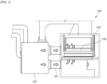
- a drying process for drying an electrode sheet 105 in which an electrode slurry is applied to a current collector through an electrode drying device 100, as shown in FIG. 1 , is used, and hot air supplied from a supply fan of a hot air supply device 101 is sprayed onto the electrode sheet 105 by a nozzle installed in a drying oven 103 through a duct 107, and the electrode sheet 105 is dried by convection of the hot air supplied in the drying oven 103.
- changes in drying conditions can alter the drying of the electrode sheet and the adhesion between the slurry and the current collector. This can be caused by differences in the structure due to residual moisture in the slurry, residual solvents, and the distribution of the binder, which can result in significant differences in the properties of the manufactured electrodes.
- Patent Document 001 Korean Patent Publication No. 10-2170893
- the present invention aims to solve the above-mentioned problems, and to provide a moisture supply device of an electrode drying device capable of supplying moisture to a non-coating part of the electrode sheet during drying of an electrode sheet in which an electrode slurry is applied to a current collector, thereby preventing the occurrence of wrinkles or cracks in the non-coating part during the drying process.
- the present invention aims to provide a moisture supply device of an electrode drying device capable of detecting and measuring the amount of moisture supplied in the drying oven in real time, and controlling the amount of moisture supplied in the drying oven through the measured value to stably supply moisture to the non-coating part.
- the present invention provides an electrode drying device including: a drying oven in which an interior space is formed for drying an electrode sheet to which an electrode slurry is applied on a current collector, and a hot air spray nozzle for spraying hot air on an electrode sheet being transferred into the drying oven, wherein a moisture supply device of the drying device includes: a water spray nozzle that sprays moisture on a non-coating part of an electrode sheet being transferred into the drying oven; a water storage tank where water is stored; and a pump installed in a water storage tank to supply water to a water spray nozzle, wherein the hot air spray nozzle dries an electrode sheet by spraying hot air, and the water spray nozzle sprays moisture on the non-coating part of the electrode sheet.
- the water spray nozzle may be provided on the upper side of the non-coating part in a number corresponding to the number of non-coating part formed on an electrode sheet.
- a flow control part installed in the water storage tank to control the flow of water supplied to the water spray nozzle through a pump may be further included.
- the flow control part may include a flow rate measurement unit that measures the flow rate of water supplied to the water spray nozzle through the pump, and a flow control unit that controls the flow of water.
- the flow rate measurement unit may include a measuring unit body having an inlet pipe into which water from a water storage tank flows and an outflow pipe connected to a pump and supplying water to the pump, a rotating body rotatably installed within the measuring unit body, and a detection sensor for detecting rotation of the rotating body.
- the inlet pipe may be provided at either the lower or upper part of one side of the measuring unit body, and the outflow pipe may be provided at either the upper or lower part of the other side of the measuring unit body.
- the rotating body may include a rotating body rotating about a rotational axis, a plurality of blades spaced apart at certain distance on an outer circumference of the rotating body, and a magnetic material installed on any one or more of the plurality of blades, wherein the detection sensor may be a Hall sensor that detect changes in the magnetic flux of the magnetic material installed on the blade.
- the flow control unit may control the flow of water supplied to the water spray nozzle by controlling the pump based on the measurement values of the flow rate measurement unit.
- the drying oven may be equipped with a moisture measurement unit for measuring the moisture of the drying oven.
- the flow of water supplied to the water spray nozzle may be controlled by controlling the pump based on the moisture measurement values measured by the moisture measurement unit.
- moisture may be supplied to a non-coating part of an electrode sheet during drying of the electrode sheet to prevent wrinkles or cracks from occurring in the non-coating part, the quality of the electrode may be improved, the amount of moisture supplied in the drying oven may be detected and measured in real time, the amount of moisture supplied in the drying oven may be controlled through the measured value to stably supply moisture to the non-coating part, and an electrode sheet of uniform quality may be manufactured.
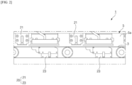
- FIG. 2 is a schematic drawing of an electrode drying device according to the present invention.
- FIG. 3 is an enlarged, schematic perspective view of a moisture supply device of an electrode drying device according to an exemplary embodiment of the present invention installed in a drying oven.
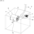
- FIG. 4 is a perspective view schematically illustrating a flow control unit installed in a water storage tank of a moisture supply device according to an exemplary embodiment of the present invention.
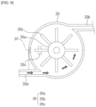
- FIG. 5 is a side view schematically illustrating the flow rate measurement unit of the flow control unit of the moisture supply device according to an exemplary embodiment of the present invention.
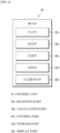
- FIG. 6 is a configuration diagram illustrating a flow control unit of a flow control part of a moisture supply device according to an exemplary embodiment of the present invention.
- FIGS. 7 through 9 are diagrams schematically illustrating an operation process of a flow measurement unit according to the present invention.
- an electrode drying device 1 is for drying an electrode sheet 3 on which an electrode slurry including an electrode active material has been applied to a current collector, and is configured by including a drying oven 5 in which an interior space is formed for drying the electrode sheet 3, and a hot air spray nozzle for spraying hot air on the electrode sheet 3 being transferred into the drying oven 5.
- the drying oven 5 has a structure in which the electrode sheet 3 on which the electrode slurry is applied to the current collector is heated and dried by hot air as it is moved by a roller, and is in the form of including a plurality of drying chambers 5a inside, but is shown simplified in the drawings of the present invention.
- the hot air spray nozzle 20 may be formed in a plurality, including an upper hot air spray nozzle 21 and a lower hot air spray nozzle 23 provided on an upper and a lower part of the electrode sheet 3, respectively, within the drying oven 5, and is connected by a duct (not shown) to a hot air generating unit (not shown) that generates hot air, for drying the electrode sheet 3 by spraying hot air supplied through the hot air generating unit 20 onto the electrode sheet 3.
- the drying oven 5 is provided with a moisture supply device 10 for supplying moisture to the non-coating part 3a formed on the electrode sheet 3 to suppress and prevent the occurrence of wrinkles and cracks and the like in the non-coating part 3a.
- the moisture supply device 10 of an electrode drying device includes a water spray nozzle 11 for spraying moisture on the non-coating part 3a of an electrode sheet 3 being transferred into the drying oven 5, a water storage tank 12 in which water is stored, and a pump 13 installed within the water storage tank 12 for supplying water to the water spray nozzle 11.
- the water storage tank 12 has a storage space for storing water formed therein, the pump 13 installed within the water storage tank 12 is connected to the water spray nozzle 11 by a discharge pipe 13a, and water from the water storage tank 12 is supplied to the water spray nozzle 11 through the discharge pipe 13a by driving the pump 13.
- the pump 13 may be made of a pump 13 driven by pressure or by rotation of an impeller, but is not limited thereto, and various changes can be practiced.
- the water spray nozzle 11 may be provided on the upper side of the non-coating part 3a in a number corresponding to the number of non-coating part 3a formed on the electrode sheet 3.
- a discharge pipe 13a connected to the pump 13 may extend to the upper side of the electrode sheet 3, and the discharge pipe 13a may be provided with a number of water spray nozzles 11 corresponding to the non-coating part 3a.
- the water spray nozzles 11 may be spaced apart at certain distance in the TD direction, which is transverse to the MD direction, which is the direction of movement of the electrode sheet 3, and may be provided correspondingly to the number of non-coating parts 3a.
- a flow control part 30 may be installed for controlling the flow of water supplied to the water spray nozzle 11 via the pump 13.
- a flow control part 30 may be installed for controlling the flow of water supplied via the pump 13 to more precisely control the amount of water supplied to the water spray nozzle 11.
- the flow control part 30 may include a flow rate measurement unit 31 for measuring the flow rate of water supplied to the water spray nozzle 11 via the pump 13, and a flow control unit 38 for controlling the flow of water thereby.
- the flow rate measurement unit 31 is for measuring the flow rate of water supplied from the water storage tank 12 to the pump 13, and includes a measuring unit body 33, a rotating body 35, and a detection sensor.
- the measuring unit body 33 includes an inlet pipe 33a into which water from the water storage tank 12 flows, and an outflow pipe 33b connected to the pump 13, which supplies water flowing into the inlet pipe 33a to the pump 13.
- the measuring unit body 33 may be fixedly installed on one side wall of the water storage tank 12.
- the rotating body 35 is rotatably installed within the measuring unit body 33.
- the internal space of the measuring unit body 33 in which the rotating body 35 is installed may be formed in a cylindrical shape.
- the rotating body 35 includes a rotating body 35a rotating about a rotational axis, a plurality of blades 35b spaced apart at certain distance on an outer circumference of the rotating body 35a, and a magnetic material 35c installed on any one or more of the plurality of blades 35b.
- water flowing into the inlet pipe 33a provided on one side of the measuring unit body 33 pressurizes the blade 35b in the measuring unit body 33 to rotate the rotating body 35, and then flows out of the outflow pipe 33b provided on the other side of the measuring unit body 33, and the water flowing out of the outflow pipe 33b is supplied to the pump 13.
- the detection sensor detects the rotation of the rotating body 35.
- the detection sensor detects the rotation of the rotating body 35 by detecting a magnetic material 35c provided on one side wall of the measuring unit body 33 opposite the rotating body 35 and provided on a blade 35b of the rotating body 35a.
- the detection sensor may be a Hall sensor that detects changes in the magnetic flux of the magnetic material 35c installed on the blade 35b.
- the detection sensor is provided on one side of the rotating body 35 to detect a change in the magnetic flux of the magnetic material 35c installed on the blade 35b when the rotating body 35 is rotated by the incoming water, thereby detecting the number of rotations and/or the rotational speed of the rotating body 35 and thereby detecting the flow rate of the water supplied to the pump 13.
- a magnetic material 35c including a magnet is provided on the blade 35b of the rotating body 35a, and a Hall sensor is installed on the side wall of the measuring unit body 33 as a detection sensor to detect the rotation of the rotating body 35 through a change in the magnetic flux of the magnetic material 35c, but other various structures and forms of sensors are possible, provided that the rotation of the rotating body 35 can be detected.
- an inlet pipe 33a may be provided at a lower or upper part of one side of the measuring unit body so as to facilitate rotation of the rotating body 35 installed within the measuring unit body 33
- an outflow pipe 33b may be provided at an upper or lower part of the other side of the measuring unit body 33 so that water introduced into the measuring unit body 33 through the inlet pipe 33a is discharged to the pump 13 after rotating the rotating body 35.
- the flow control unit 38 is for controlling the flow of water supplied to the water spray nozzle 11 according to measurement values including a flow rate measured via the flow rate measurement unit 31, to which the pump 13 is controllably connected.
- the flow control unit 38 may include a receiving part 38a, a calculation part 38b, a control part 38c, a storage part 38d, and a display part 38e.
- the receiving part 38a may receive a measurement value measured via the flow rate measurement unit 31. That is, the receiving part 38a receives a change in the magnetic flux of the magnetic material 35c detected via the detection sensor in the measuring unit body 33.
- the calculation part 38b may calculate a flow rate by the number of rotations and/or a rotational speed of the rotating body 35 per minute (m/s) from the measurement values received via the receiving part 38a.
- calculation part 38b may calculate the flow rate supplied to the water spray nozzle 11 via the pump 13 by the number of rotations and/or the rotational speed of the rotating body 35.
- the control part 38c may control the pump 13 to increase or decrease the amount of water supplied when the flow rate of water supplied to the pump 13 through the calculation value of the calculation part 38b is slow or fast, or when the amount of flow of water sprayed onto the non-coating part 3a of the electrode sheet 3 through the water spray nozzle 11 is less or more.
- the storage part 38d may store various information such as drying condition of the electrode sheet 3, humidity condition, measurement value, set water supply amount, etc.
- the storage part 38d is a storage module capable of inputting/outputting information such as ROM memory, flash memory, CF card (Compact Flash Card), SD card (Secure Digital Card), etc. and is preferably provided within the flow control unit 38, but it is also possible to be provided in a separate device and connected to it, without limitation.
- the display part 38e may display the air volume of the hot air sprayed within the electrode drying device 1, the amount of moisture sprayed, and the amount of water supplied, etc. to visually recognize the operator.
- the flow control unit 38 may further include a comparing part and a judging part. Specifically, the flow control unit 38 may further include a comparing part that compares a detection count of the magnetic material 35c detected through the detection sensor or compares a rotation speed per hour of the rotating body 35 according to the detection time with a preset setting value, and a judging part that judges the amount of water spray on the non-coating part 3a of the electrode sheet 3 through the water spray nozzle 11 based on the comparison value compared through the comparing part.
- the flow control unit 38 may further include an alarm part, and through the alarm part, a warning sound or a notification sound may be generated in the event of an abnormal situation or the like in the electrode drying device 1 to make the manager aware of the abnormal situation.
- the flow control unit 38 may control the flow supplied to the water spray nozzle 11 by controlling the pressure of the pump 13 and/or the rotational speed of the impeller to increase or decrease according to the measurement value of the flow rate measurement unit 31, thereby controlling the amount of water supplied to the water spray nozzle 11 and, consequently, controlling the amount of water sprayed to the non-coating part 3a of the electrode sheet 3 through the water spray nozzle 11.
- a change in the magnetic flux of the magnetic material 35c detected through the detection sensor may cause the pressure or rotational speed of the pump 13 to be increased to increase the flow of the pump 13 and consequently increase the amount of water supplied to the water spray nozzle 11 if the rotational speed of the rotating body 35 is slow, and the pressure or rotational speed of the pump 13 to be decreased to decrease the flow of the pump 13 and consequently decrease the amount of water supplied to the water spray nozzle 11 if the rotational speed of the rotating body 35 is fast.
- the rotation speed of the rotating body 35 is slower than the preset rotational speed through the change in the magnetic flux of the magnetic material 35c detected through the detection sensor, it may be determined that the current water supply is less than the actual set water supply, and the pressure or rotational speed of the pump 13 is increased to increase the flow of the pump 13, thereby increasing the amount of water supplied to the water spray nozzle 11, and if the rotational speed of the rotating body 35 is faster than the preset rotational speed, it may be determined that the current water supply is greater than the actual preset water supply, and decrease the pressure or rotational speed of the pump 13 to decrease the flow of the pump 13, thereby decreasing the amount of water supplied to the water spray nozzle 11.
- the amount of water supplied to the water spray nozzle 11 can be adjusted by controlling the pressure or rotational speed of the pump 13 to adjust the flow of the pump 13, as described above.
- the electrode sheet 3 with the electrode slurry applied on the current collector is transferred into the drying oven 5 of the electrode drying device 1, and hot air generated by the heat generating device is sprayed onto the electrode sheet 3 moving in the drying oven 5 through the hot air spray nozzle.
- water is sprayed from the water spray nozzle 11 to the non-coating part 3a of the electrode sheet 3. That is, by driving the pump 13, water in the water storage tank 12 is supplied to the water spray nozzle 11 connected by the pump 13 and the discharge pipe 13a, and the water spray nozzle 11 sprays water to the non-coating part 3a of the electrode sheet 3.
- the amount of water supplied to the water spray nozzle 11 via the pump 13 may be controlled more precisely by the flow control unit 30. That is, the amount of water supplied to the water spray nozzle 11 may be controlled by controlling the flow of water supplied by the pump 13 through a measurement value measured through the flow rate measurement unit 31 of the flow control part 30.
- water introduced into the inlet of the measuring unit body 33 of the flow rate measuring unit 31 by driving the pump 13 pressurizes the blade 35b to rotate the rotating body 35, and the magnetic material 35c installed on the blade 35b is detected by the detection sensor, detecting a change in the magnetic flux of the magnetic material 35c to measure the rotational speed of the rotating body 35, and controlling the flow of the pump 13 through the measured rotational speed of the rotating body 35 may control the amount of water supplied to the water spray nozzle 11.
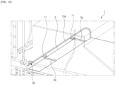
- FIG. 10 is a diagram schematically illustrating a moisture measurement unit installed on one side of a moisture supply device of an electrode drying device according to another exemplary embodiment of the present invention.
- the moisture supply device 10 of the electrode drying device according to another exemplary embodiment of the present invention is provided with a moisture measurement unit 40 for measuring moisture in the drying oven 5.
- the moisture measurement unit 40 for measuring the moisture in the drying oven 5 is preferably provided at a position proximate to the non-coating part 3a of the electrode sheet 3 moving in the drying oven 5, but the position of the moisture measurement unit 40 can be varied without limitation.
- the pump 13 may be controlled to control the flow of water supplied to the water spray nozzle 11 based on a moisture measurement value including a moisture amount or moisture percentage measured by the moisture measurement unit 40.
- the moisture measurement unit 40 may comprise a sensor for measuring moisture in the drying oven 5, and the moisture measurement unit 40 may be connected to the flow control unit 38 of the flow control part 30, and through the moisture measurement value measured by the moisture measurement unit 40, the flow control unit 38 of the flow control part 30 may control the flow of the pump 13 to regulate the amount of water supplied into the drying oven 5.
- the amount of water supplied to the water spray nozzle 11 in the drying oven 5 can be decreased when the amount of moisture or the moisture percentage in the drying oven 5 is higher than the preset amount of moisture or the moisture percentage, and the amount of water supplied to the water spray nozzle 11 in the drying oven 5 can be increased when the amount of moisture or the moisture percentage in the drying oven 5 is lower than the preset amount of moisture or the moisture percentage.
- the moisture measurement value measured by the moisture measurement unit 40 if the moisture amount or moisture percentage in the drying oven 5 is higher than the range of the preset moisture amount or moisture percentage, the amount of water supplied to the water spray nozzle 11 in the drying oven 5 can be reduced, and if the moisture amount or moisture percentage in the drying oven 5 is lower than the range of the preset moisture amount or moisture percentage, the amount of water supplied to the water spray nozzle 11 in the drying oven 5 can be increased.
- the supply amount of water sprayed onto the non-coating part 3a of the electrode sheet 3 may be more precisely controlled.
Landscapes
- Engineering & Computer Science (AREA)
- Mechanical Engineering (AREA)
- General Engineering & Computer Science (AREA)
- Chemical & Material Sciences (AREA)
- Physics & Mathematics (AREA)
- General Chemical & Material Sciences (AREA)
- Electrochemistry (AREA)
- General Physics & Mathematics (AREA)
- Chemical Kinetics & Catalysis (AREA)
- Manufacturing & Machinery (AREA)
- Microbiology (AREA)
- Aviation & Aerospace Engineering (AREA)
- Life Sciences & Earth Sciences (AREA)
- Analytical Chemistry (AREA)
- Fluid Mechanics (AREA)
- Electromagnetism (AREA)
- Drying Of Solid Materials (AREA)
- Battery Electrode And Active Subsutance (AREA)
- Coating Apparatus (AREA)
Abstract
Description
- The present invention relates to a moisture supply device for an electrode drying device.
- More specifically, it relates to a moisture supply device of an electrode drying device which can supply moisture to a non-coating part of an electrode sheet during drying of an electrode sheet on which an electrode slurry is applied to a current collector, thereby preventing wrinkling, cracking, and the like of the non-coating part during the drying process.
- This application claims the benefit of priority to
Korean Patent Application No. 10-2022-0113047, filed on September 6, 2022 - In recent years, important trends in the development of the electronics industry can be summarized as the wireless and mobile trends in devices and the transition from analog to digital. Examples include the rapid proliferation of cordless phones (i.e., cell phones) and laptops, and the transition from analog to digital cameras.
- Along with these trends, research and development of secondary batteries is actively underway, and the types of applications using secondary batteries are diversifying due to their advantages, and it is expected that in the future, secondary batteries will be applied to many more fields and products than today.
- Here, secondary batteries are not only being used in portable devices such as cell phones, laptops, and camcorders, but also as an energy source for electric vehicles and hybrid electric vehicles, which are being proposed as a way to solve air pollution such as existing gasoline and diesel vehicles that use fossil fuels.
- Generally, secondary batteries are classified based on the shape of the battery case. There are cylindrical and prismatic batteries where an electrode assembly is embedded in cylindrical and prismatic metal cans, respectively, and pouch-type battery cells where an electrode assembly is embedded in an aluminum laminate sheet pouch-type case.
- Furthermore, the electrode assembly embedded in the battery case is a power generator capable of charging and discharging by comprising a positive electrode plate, a negative electrode plate, and a separator interposed between the positive electrode plate and the negative electrode plate, and is classified into a jelly-roll type that is wound by interposing a separator between the positive electrode plate and the negative electrode plate in the form of a long sheet on which each active material is applied, and a stack-type that sequentially stacks a plurality of positive electrode and negative electrode plates formed in a predetermined size while interposing a separator.
- These secondary batteries are categorized into lithium-ion batteries, lithium-ion polymer batteries, and lithium polymer batteries, depending on the composition of electrodes and electrolytes. Typically, the electrodes of these lithium secondary batteries are formed by coating the positive electrode or negative electrode active material onto a current collector made of aluminum or copper sheets, mesh, film, foil, and the like and then drying it.
- Here, a drying process for drying an
electrode sheet 105, in which an electrode slurry is applied to a current collector through anelectrode drying device 100, as shown inFIG. 1 , is used, and hot air supplied from a supply fan of a hotair supply device 101 is sprayed onto theelectrode sheet 105 by a nozzle installed in adrying oven 103 through aduct 107, and theelectrode sheet 105 is dried by convection of the hot air supplied in thedrying oven 103. - In such cases, changes in drying conditions can alter the drying of the electrode sheet and the adhesion between the slurry and the current collector. This can be caused by differences in the structure due to residual moisture in the slurry, residual solvents, and the distribution of the binder, which can result in significant differences in the properties of the manufactured electrodes.
- Meanwhile, there was a problem that at least one non-coating part not coated with a slurry is formed on the electrode sheet which is moved and supplied to the electrode drying device, and when the electrode sheet is dried by hot air in the drying oven, the part of the electrode sheet containing slurry shrinks, and due to the shrinkage of the part of the electrode sheet, the part of the electrode sheet not containing slurry is subjected to concentrated stress, which may cause wrinkles or cracks in the non-coating part, which may cause a deterioration of the quality of the electrode.
- (Patent Document 001)
Korean Patent Publication No. 10-2170893 - The present invention aims to solve the above-mentioned problems, and to provide a moisture supply device of an electrode drying device capable of supplying moisture to a non-coating part of the electrode sheet during drying of an electrode sheet in which an electrode slurry is applied to a current collector, thereby preventing the occurrence of wrinkles or cracks in the non-coating part during the drying process.
- In addition, the present invention aims to provide a moisture supply device of an electrode drying device capable of detecting and measuring the amount of moisture supplied in the drying oven in real time, and controlling the amount of moisture supplied in the drying oven through the measured value to stably supply moisture to the non-coating part.
- In order to achieve the aforementioned objectives, the present invention provides an electrode drying device including: a drying oven in which an interior space is formed for drying an electrode sheet to which an electrode slurry is applied on a current collector, and a hot air spray nozzle for spraying hot air on an electrode sheet being transferred into the drying oven, wherein a moisture supply device of the drying device includes: a water spray nozzle that sprays moisture on a non-coating part of an electrode sheet being transferred into the drying oven; a water storage tank where water is stored; and a pump installed in a water storage tank to supply water to a water spray nozzle, wherein the hot air spray nozzle dries an electrode sheet by spraying hot air, and the water spray nozzle sprays moisture on the non-coating part of the electrode sheet.
- As an exemplary embodiment, the water spray nozzle may be provided on the upper side of the non-coating part in a number corresponding to the number of non-coating part formed on an electrode sheet.
- As another exemplary embodiment, a flow control part installed in the water storage tank to control the flow of water supplied to the water spray nozzle through a pump may be further included.
- As a specific exemplary embodiment, the flow control part may include a flow rate measurement unit that measures the flow rate of water supplied to the water spray nozzle through the pump, and a flow control unit that controls the flow of water.
- As a more specific exemplary embodiment, the flow rate measurement unit may include a measuring unit body having an inlet pipe into which water from a water storage tank flows and an outflow pipe connected to a pump and supplying water to the pump, a rotating body rotatably installed within the measuring unit body, and a detection sensor for detecting rotation of the rotating body.
- As another specific exemplary embodiment, the inlet pipe may be provided at either the lower or upper part of one side of the measuring unit body, and the outflow pipe may be provided at either the upper or lower part of the other side of the measuring unit body.
- As an exemplary embodiment, the rotating body may include a rotating body rotating about a rotational axis, a plurality of blades spaced apart at certain distance on an outer circumference of the rotating body, and a magnetic material installed on any one or more of the plurality of blades, wherein the detection sensor may be a Hall sensor that detect changes in the magnetic flux of the magnetic material installed on the blade.
- As another exemplary embodiment, the flow control unit may control the flow of water supplied to the water spray nozzle by controlling the pump based on the measurement values of the flow rate measurement unit.
- As an exemplary embodiment, the drying oven may be equipped with a moisture measurement unit for measuring the moisture of the drying oven.
- As a specific exemplary embodiment, the flow of water supplied to the water spray nozzle may be controlled by controlling the pump based on the moisture measurement values measured by the moisture measurement unit.
- According to the present invention, moisture may be supplied to a non-coating part of an electrode sheet during drying of the electrode sheet to prevent wrinkles or cracks from occurring in the non-coating part, the quality of the electrode may be improved, the amount of moisture supplied in the drying oven may be detected and measured in real time, the amount of moisture supplied in the drying oven may be controlled through the measured value to stably supply moisture to the non-coating part, and an electrode sheet of uniform quality may be manufactured.
-
-
FIG. 1 is a schematic diagram of a typical configuration of an electrode drying device according to the prior art. -
FIG. 2 is a schematic drawing of an electrode drying device according to the present invention. -
FIG. 3 is an enlarged, schematic perspective view of a moisture supply device of an electrode drying device according to an exemplary embodiment of the present invention installed in a drying oven. -
FIG. 4 is a perspective view schematically illustrating a flow control unit installed in a water storage tank of a moisture supply device according to an exemplary embodiment of the present invention. -
FIG. 5 is a side view schematically illustrating the flow rate measurement unit of the flow control unit of the moisture supply device according to an exemplary embodiment of the present invention. -
FIG. 6 is a block diagram illustrating a flow control unit of a flow control part of a moisture supply device according to an exemplary embodiment of the present invention. -
FIGS. 7 through 9 are diagrams schematically illustrating an operation process of a flow measurement unit according to the present invention. -
FIG. 10 is a diagram schematically illustrating a moisture measurement unit installed on one side of a moisture supply device of an electrode drying device according to another exemplary embodiment of the present invention. - The following is a detailed description of the present invention. It should be noted that the terms or words used in this specification and the claims of the patent are not to be construed in their ordinary or dictionary sense, but rather in a sense and concept consistent with the technical idea of the invention, based on the principle that the inventor may properly define the concept of a term to best describe his invention.
- The terms "comprise," "include" and "have" are used herein to designate the presence of characteristics, numbers, steps, actions, components or members described in the specification or a combination thereof, and it should be understood that the possibility of the presence or addition of one or more other characteristics, numbers, steps, actions, components, members or a combination thereof is not excluded in advance.
- In addition, when a part of a layer, a film, a region or a plate is disposed "on" another part, this includes not only a case in which one part is disposed "directly on" another part, but a case in which a third part is interposed there between. In contrast, when a part of a layer, a film, a region or a plate is disposed "under" another part, this includes not only a case in which one part is disposed "directly under" another part, but a case in which a third part is interposed there between. In addition, in this application, "on" may include not only a case of disposed on an upper part but also a case of disposed on a lower part.
-
FIG. 2 is a schematic drawing of an electrode drying device according to the present invention.FIG. 3 is an enlarged, schematic perspective view of a moisture supply device of an electrode drying device according to an exemplary embodiment of the present invention installed in a drying oven.FIG. 4 is a perspective view schematically illustrating a flow control unit installed in a water storage tank of a moisture supply device according to an exemplary embodiment of the present invention.FIG. 5 is a side view schematically illustrating the flow rate measurement unit of the flow control unit of the moisture supply device according to an exemplary embodiment of the present invention.FIG. 6 is a configuration diagram illustrating a flow control unit of a flow control part of a moisture supply device according to an exemplary embodiment of the present invention.FIGS. 7 through 9 are diagrams schematically illustrating an operation process of a flow measurement unit according to the present invention. - As illustrated in the drawings, an
electrode drying device 1 according to the present invention is for drying anelectrode sheet 3 on which an electrode slurry including an electrode active material has been applied to a current collector, and is configured by including adrying oven 5 in which an interior space is formed for drying theelectrode sheet 3, and a hot air spray nozzle for spraying hot air on theelectrode sheet 3 being transferred into the dryingoven 5. - The
drying oven 5 has a structure in which theelectrode sheet 3 on which the electrode slurry is applied to the current collector is heated and dried by hot air as it is moved by a roller, and is in the form of including a plurality ofdrying chambers 5a inside, but is shown simplified in the drawings of the present invention. - And, the hot
air spray nozzle 20 may be formed in a plurality, including an upper hotair spray nozzle 21 and a lower hotair spray nozzle 23 provided on an upper and a lower part of theelectrode sheet 3, respectively, within the dryingoven 5, and is connected by a duct (not shown) to a hot air generating unit (not shown) that generates hot air, for drying theelectrode sheet 3 by spraying hot air supplied through the hotair generating unit 20 onto theelectrode sheet 3. - Here, the drying
oven 5 is provided with amoisture supply device 10 for supplying moisture to thenon-coating part 3a formed on theelectrode sheet 3 to suppress and prevent the occurrence of wrinkles and cracks and the like in thenon-coating part 3a. - Specifically, the
moisture supply device 10 of an electrode drying device according to an exemplary embodiment of the present invention includes awater spray nozzle 11 for spraying moisture on thenon-coating part 3a of anelectrode sheet 3 being transferred into the dryingoven 5, awater storage tank 12 in which water is stored, and apump 13 installed within thewater storage tank 12 for supplying water to thewater spray nozzle 11. - The
water storage tank 12 has a storage space for storing water formed therein, thepump 13 installed within thewater storage tank 12 is connected to thewater spray nozzle 11 by adischarge pipe 13a, and water from thewater storage tank 12 is supplied to thewater spray nozzle 11 through thedischarge pipe 13a by driving thepump 13. - In this case, the
pump 13 may be made of apump 13 driven by pressure or by rotation of an impeller, but is not limited thereto, and various changes can be practiced. - Here, the
water spray nozzle 11 may be provided on the upper side of thenon-coating part 3a in a number corresponding to the number ofnon-coating part 3a formed on theelectrode sheet 3. - To this end, a
discharge pipe 13a connected to thepump 13 may extend to the upper side of theelectrode sheet 3, and thedischarge pipe 13a may be provided with a number ofwater spray nozzles 11 corresponding to thenon-coating part 3a. - In this case, the
water spray nozzles 11 may be spaced apart at certain distance in the TD direction, which is transverse to the MD direction, which is the direction of movement of theelectrode sheet 3, and may be provided correspondingly to the number ofnon-coating parts 3a. - By the structure as described above, it is possible to prevent wrinkling and cracking of the
non-coating part 3a of theelectrode sheet 3 by spraying hot air on theelectrode sheet 3 from the hot air spray nozzle and spraying moisture on thenon-coating part 3a from thewater spray nozzle 11 during drying. - Meanwhile, within the
water storage tank 12, aflow control part 30 may be installed for controlling the flow of water supplied to thewater spray nozzle 11 via thepump 13. In other words, aflow control part 30 may be installed for controlling the flow of water supplied via thepump 13 to more precisely control the amount of water supplied to thewater spray nozzle 11. - Here, the
flow control part 30 may include a flowrate measurement unit 31 for measuring the flow rate of water supplied to thewater spray nozzle 11 via thepump 13, and aflow control unit 38 for controlling the flow of water thereby.
The flowrate measurement unit 31 is for measuring the flow rate of water supplied from thewater storage tank 12 to thepump 13, and includes a measuringunit body 33, a rotatingbody 35, and a detection sensor. - The measuring
unit body 33 includes aninlet pipe 33a into which water from thewater storage tank 12 flows, and anoutflow pipe 33b connected to thepump 13, which supplies water flowing into theinlet pipe 33a to thepump 13.
Here, the measuringunit body 33 may be fixedly installed on one side wall of thewater storage tank 12. - The rotating
body 35 is rotatably installed within the measuringunit body 33. For this purpose, the internal space of the measuringunit body 33 in which therotating body 35 is installed may be formed in a cylindrical shape. - The rotating
body 35 includes arotating body 35a rotating about a rotational axis, a plurality ofblades 35b spaced apart at certain distance on an outer circumference of therotating body 35a, and amagnetic material 35c installed on any one or more of the plurality ofblades 35b. - In accordance with the structure as described above, water flowing into the
inlet pipe 33a provided on one side of the measuringunit body 33 pressurizes theblade 35b in the measuringunit body 33 to rotate therotating body 35, and then flows out of theoutflow pipe 33b provided on the other side of the measuringunit body 33, and the water flowing out of theoutflow pipe 33b is supplied to thepump 13. - The detection sensor detects the rotation of the
rotating body 35. For this purpose, the detection sensor detects the rotation of therotating body 35 by detecting amagnetic material 35c provided on one side wall of the measuringunit body 33 opposite the rotatingbody 35 and provided on ablade 35b of therotating body 35a. - To this end, the detection sensor may be a Hall sensor that detects changes in the magnetic flux of the
magnetic material 35c installed on theblade 35b. - In this way, the detection sensor is provided on one side of the
rotating body 35 to detect a change in the magnetic flux of themagnetic material 35c installed on theblade 35b when therotating body 35 is rotated by the incoming water, thereby detecting the number of rotations and/or the rotational speed of therotating body 35 and thereby detecting the flow rate of the water supplied to thepump 13. - In an exemplary embodiment of the present invention, a
magnetic material 35c including a magnet is provided on theblade 35b of therotating body 35a, and a Hall sensor is installed on the side wall of the measuringunit body 33 as a detection sensor to detect the rotation of therotating body 35 through a change in the magnetic flux of themagnetic material 35c, but other various structures and forms of sensors are possible, provided that the rotation of therotating body 35 can be detected. - Here, an
inlet pipe 33a may be provided at a lower or upper part of one side of the measuring unit body so as to facilitate rotation of therotating body 35 installed within the measuringunit body 33, and anoutflow pipe 33b may be provided at an upper or lower part of the other side of the measuringunit body 33 so that water introduced into the measuringunit body 33 through theinlet pipe 33a is discharged to thepump 13 after rotating therotating body 35. - The
flow control unit 38 is for controlling the flow of water supplied to thewater spray nozzle 11 according to measurement values including a flow rate measured via the flowrate measurement unit 31, to which thepump 13 is controllably connected. - The
flow control unit 38 may include a receivingpart 38a, acalculation part 38b, acontrol part 38c, astorage part 38d, and adisplay part 38e. - The receiving
part 38a may receive a measurement value measured via the flowrate measurement unit 31. That is, the receivingpart 38a receives a change in the magnetic flux of themagnetic material 35c detected via the detection sensor in the measuringunit body 33. - The
calculation part 38b may calculate a flow rate by the number of rotations and/or a rotational speed of therotating body 35 per minute (m/s) from the measurement values received via the receivingpart 38a. - In addition, the
calculation part 38b may calculate the flow rate supplied to thewater spray nozzle 11 via thepump 13 by the number of rotations and/or the rotational speed of therotating body 35. - The
control part 38c may control thepump 13 to increase or decrease the amount of water supplied when the flow rate of water supplied to thepump 13 through the calculation value of thecalculation part 38b is slow or fast, or when the amount of flow of water sprayed onto thenon-coating part 3a of theelectrode sheet 3 through thewater spray nozzle 11 is less or more. - The
storage part 38d may store various information such as drying condition of theelectrode sheet 3, humidity condition, measurement value, set water supply amount, etc. Thestorage part 38d is a storage module capable of inputting/outputting information such as ROM memory, flash memory, CF card (Compact Flash Card), SD card (Secure Digital Card), etc. and is preferably provided within theflow control unit 38, but it is also possible to be provided in a separate device and connected to it, without limitation. - The
display part 38e may display the air volume of the hot air sprayed within theelectrode drying device 1, the amount of moisture sprayed, and the amount of water supplied, etc. to visually recognize the operator. - Meanwhile, the
flow control unit 38 may further include a comparing part and a judging part. Specifically, theflow control unit 38 may further include a comparing part that compares a detection count of themagnetic material 35c detected through the detection sensor or compares a rotation speed per hour of therotating body 35 according to the detection time with a preset setting value, and a judging part that judges the amount of water spray on thenon-coating part 3a of theelectrode sheet 3 through thewater spray nozzle 11 based on the comparison value compared through the comparing part. - In addition, the
flow control unit 38 may further include an alarm part, and through the alarm part, a warning sound or a notification sound may be generated in the event of an abnormal situation or the like in theelectrode drying device 1 to make the manager aware of the abnormal situation. - As mentioned above, the
flow control unit 38 may control the flow supplied to thewater spray nozzle 11 by controlling the pressure of thepump 13 and/or the rotational speed of the impeller to increase or decrease according to the measurement value of the flowrate measurement unit 31, thereby controlling the amount of water supplied to thewater spray nozzle 11 and, consequently, controlling the amount of water sprayed to thenon-coating part 3a of theelectrode sheet 3 through thewater spray nozzle 11. - For example, a change in the magnetic flux of the
magnetic material 35c detected through the detection sensor may cause the pressure or rotational speed of thepump 13 to be increased to increase the flow of thepump 13 and consequently increase the amount of water supplied to thewater spray nozzle 11 if the rotational speed of therotating body 35 is slow, and the pressure or rotational speed of thepump 13 to be decreased to decrease the flow of thepump 13 and consequently decrease the amount of water supplied to thewater spray nozzle 11 if the rotational speed of therotating body 35 is fast. - In addition, if the rotation speed of the
rotating body 35 is slower than the preset rotational speed through the change in the magnetic flux of themagnetic material 35c detected through the detection sensor, it may be determined that the current water supply is less than the actual set water supply, and the pressure or rotational speed of thepump 13 is increased to increase the flow of thepump 13, thereby increasing the amount of water supplied to thewater spray nozzle 11, and if the rotational speed of therotating body 35 is faster than the preset rotational speed, it may be determined that the current water supply is greater than the actual preset water supply, and decrease the pressure or rotational speed of thepump 13 to decrease the flow of thepump 13, thereby decreasing the amount of water supplied to thewater spray nozzle 11. - Furthermore, even when the rotational speed of the
rotating body 35 is slow outside the range of the preset rotational speed through a change in the magnetic flux of themagnetic material 35c detected through the detection sensor, or when the rotational speed of therotating body 35 is fast outside the range of the preset rotational speed, the amount of water supplied to thewater spray nozzle 11 can be adjusted by controlling the pressure or rotational speed of thepump 13 to adjust the flow of thepump 13, as described above. - Hereinafter, the operation process of the moisture supply device of the electrode drying device according to an exemplary embodiment of the present invention will be briefly described with reference to the drawings.
- First, the
electrode sheet 3 with the electrode slurry applied on the current collector is transferred into the dryingoven 5 of theelectrode drying device 1, and hot air generated by the heat generating device is sprayed onto theelectrode sheet 3 moving in the dryingoven 5 through the hot air spray nozzle. - At this time, water is sprayed from the
water spray nozzle 11 to thenon-coating part 3a of theelectrode sheet 3. That is, by driving thepump 13, water in thewater storage tank 12 is supplied to thewater spray nozzle 11 connected by thepump 13 and thedischarge pipe 13a, and thewater spray nozzle 11 sprays water to thenon-coating part 3a of theelectrode sheet 3. - In this way, by separately spraying moisture on the
non-coating part 3a during drying of theelectrode sheet 3, it is possible to prevent the occurrence of wrinkles and cracks in thenon-coating part 3a, which is subjected to concentrated stress by shrinkage of the electrode due to drying. - Meanwhile, as illustrated in
FIGS. 7 to 9 , the amount of water supplied to thewater spray nozzle 11 via thepump 13 may be controlled more precisely by theflow control unit 30. That is, the amount of water supplied to thewater spray nozzle 11 may be controlled by controlling the flow of water supplied by thepump 13 through a measurement value measured through the flowrate measurement unit 31 of theflow control part 30. - That is, water introduced into the inlet of the measuring
unit body 33 of the flowrate measuring unit 31 by driving thepump 13 pressurizes theblade 35b to rotate therotating body 35, and themagnetic material 35c installed on theblade 35b is detected by the detection sensor, detecting a change in the magnetic flux of themagnetic material 35c to measure the rotational speed of therotating body 35, and controlling the flow of thepump 13 through the measured rotational speed of therotating body 35 may control the amount of water supplied to thewater spray nozzle 11. -
FIG. 10 is a diagram schematically illustrating a moisture measurement unit installed on one side of a moisture supply device of an electrode drying device according to another exemplary embodiment of the present invention.
As shown in the drawing, themoisture supply device 10 of the electrode drying device according to another exemplary embodiment of the present invention is provided with amoisture measurement unit 40 for measuring moisture in the dryingoven 5. - In this case, the
moisture measurement unit 40 for measuring the moisture in the dryingoven 5 is preferably provided at a position proximate to thenon-coating part 3a of theelectrode sheet 3 moving in the dryingoven 5, but the position of themoisture measurement unit 40 can be varied without limitation. - The
pump 13 may be controlled to control the flow of water supplied to thewater spray nozzle 11 based on a moisture measurement value including a moisture amount or moisture percentage measured by themoisture measurement unit 40. - In this case, the
moisture measurement unit 40 may comprise a sensor for measuring moisture in the dryingoven 5, and themoisture measurement unit 40 may be connected to theflow control unit 38 of theflow control part 30, and through the moisture measurement value measured by themoisture measurement unit 40, theflow control unit 38 of theflow control part 30 may control the flow of thepump 13 to regulate the amount of water supplied into the dryingoven 5. - Specifically, through the moisture measurement value measured by the
moisture measurement unit 40, the amount of water supplied to thewater spray nozzle 11 in the dryingoven 5 can be decreased when the amount of moisture or the moisture percentage in the dryingoven 5 is higher than the preset amount of moisture or the moisture percentage, and the amount of water supplied to thewater spray nozzle 11 in the dryingoven 5 can be increased when the amount of moisture or the moisture percentage in the dryingoven 5 is lower than the preset amount of moisture or the moisture percentage. - Furthermore, through the moisture measurement value measured by the
moisture measurement unit 40, if the moisture amount or moisture percentage in the dryingoven 5 is higher than the range of the preset moisture amount or moisture percentage, the amount of water supplied to thewater spray nozzle 11 in the dryingoven 5 can be reduced, and if the moisture amount or moisture percentage in the dryingoven 5 is lower than the range of the preset moisture amount or moisture percentage, the amount of water supplied to thewater spray nozzle 11 in the dryingoven 5 can be increased. - As mentioned above, by regulating the amount of water supplied from the
water storage tank 12 to thewater spray nozzle 11 by controlling the flow of thepump 13 according to a measurement value measured through the flowrate measurement unit 31 of theflow control part 30, or by controlling the flow of thepump 13 according to a moisture measurement value in the dryingoven 5 measured through themoisture measurement unit 40 to adjust the supply amount of water supplied from thewater storage tank 12 to thewater spray nozzle 11, the supply amount of water sprayed onto thenon-coating part 3a of theelectrode sheet 3 may be more precisely controlled. - While the present invention has been shown and described with reference to certain embodiments, it will be readily apparent to one of ordinary skill in the art that various modifications and changes can be made without departing from the ideas and scope of the invention as set forth in the appended claims.
-
- 1: ELECTRODE DRYING DEVICE
- 3: ELECTRODE SHEET
- 3a: NON-COATING PART
- 5: DRYING OVEN
- 5a: DRYING ROOM
- 10: MOISTURE SUPPLY DEVICE
- 11: WATER SPRAY NOZZLE
- 12: WATER STORAGE TANK
- 13: PUMP
- 13a: DISCHARGE PIPE
- 30: FLOW CONTROL PART
- 31: FLOW RATE MEASUREMENT UNIT
- 33: MEASURING UNIT BODY
- 33 a: INLET PIPE
- 33b: OUTFLOW PIPE
- 35: ROTATING BODY
- 35a: ROTATING BODY
- 35b: BLADE
- 35c: MAGNETIC MATERIAL
- 37: DETECTION SENSOR
- 38: FLOW CONTROL UNIT
- 38a: RECEIVING PART
- 38b: CALCULATION PART
- 38c: CONTROL PART
- 38d: STORAGE PART
- 38e: DISPLAY PART
- 40: MOISTURE MEASUREMENT UNIT
Claims (10)
- In an electrode drying device comprising: a drying oven in which an interior space is formed for drying an electrode sheet to which an electrode slurry is applied on a current collector, and a hot air spray nozzle for spraying hot air on an electrode sheet being transferred into the drying oven,
a moisture supply device of the drying device comprises:a water spray nozzle that sprays moisture on a non-coating part of an electrode sheet being transferred into the drying oven;a water storage tank where water is stored; anda pump installed in a water storage tank to supply water to a water spray nozzle; whereinthe hot air spray nozzle dries an electrode sheet by spraying hot air, and the water spray nozzle sprays moisture on the non-coating part of the electrode sheet. - The moisture supply device of the electrode drying device according to claim 1, wherein
the water spray nozzle is provided on the upper side of the non-coating part in a number corresponding to the number of non-coating part formed on an electrode sheet. - The moisture supply device of the electrode drying device according to claim 1, further comprising:
a flow control part installed in the water storage tank to control the flow of water supplied to the water spray nozzle through a pump. - The moisture supply device of the electrode drying device according to claim 3, wherein
the flow control part includes a flow rate measurement unit that measures the flow rate of water supplied to the water spray nozzle through the pump, and a flow control unit that controls the flow of water. - The moisture supply device of the electrode drying device according to claim 4, wherein
the flow rate measurement unit includes a measuring unit body having an inlet pipe into which water from a water storage tank flows and an outflow pipe connected to a pump and supplying water to the pump, a rotating body rotatably installed within the measuring unit body, and a detection sensor for detecting rotation of the rotating body. - The moisture supply device of the electrode drying device according to claim 5, wherein
the inlet pipe is provided at either the lower or upper part of one side of the measuring unit body, and the outflow pipe is provided at either the upper or lower part of the other side of the measuring unit body. - The moisture supply device of the electrode drying device according to claim 5, whereinthe rotating body includes a rotating body rotating about a rotational axis, a plurality of blades spaced apart at certain distance on an outer circumference of the rotating body, and a magnetic material installed on any one or more of the plurality of blades, whereinthe detection sensor is a Hall sensor that detect changes in the magnetic flux of the magnetic material installed on the blade.
- The moisture supply device of the electrode drying device according to claim 4, wherein
the flow control unit controls the flow of water supplied to the water spray nozzle by controlling the pump based on the measurement values of the flow rate measurement unit. - The moisture supply device of the electrode drying device according to claim 3, wherein
the drying oven is equipped with a moisture measurement unit for measuring the moisture of the drying oven. - The moisture supply device of the electrode drying device according to claim 9, wherein
the flow of water supplied to the water spray nozzle is controlled by controlling the pump based on the moisture measurement values measured by the moisture measurement unit.
Applications Claiming Priority (2)
| Application Number | Priority Date | Filing Date | Title |
|---|---|---|---|
| KR1020220113047A KR20240034022A (en) | 2022-09-06 | 2022-09-06 | Water spraying apparatus of apparatus for drying electrode |
| PCT/KR2023/013279 WO2024054011A1 (en) | 2022-09-06 | 2023-09-05 | Moisture-supplying device of electrode-drying apparatus |
Publications (2)
| Publication Number | Publication Date |
|---|---|
| EP4475202A1 true EP4475202A1 (en) | 2024-12-11 |
| EP4475202A4 EP4475202A4 (en) | 2025-09-17 |
Family
ID=90191584
Family Applications (1)
| Application Number | Title | Priority Date | Filing Date |
|---|---|---|---|
| EP23863478.6A Pending EP4475202A4 (en) | 2022-09-06 | 2023-09-05 | MOISTURE SUPPLY DEVICE FOR AN ELECTRODE DRYING DEVICE |
Country Status (6)
| Country | Link |
|---|---|
| US (1) | US20250207856A1 (en) |
| EP (1) | EP4475202A4 (en) |
| JP (1) | JP2025511521A (en) |
| KR (1) | KR20240034022A (en) |
| CN (1) | CN118872088A (en) |
| WO (1) | WO2024054011A1 (en) |
Families Citing this family (2)
| Publication number | Priority date | Publication date | Assignee | Title |
|---|---|---|---|---|
| KR102917916B1 (en) * | 2021-09-08 | 2026-01-23 | 주식회사 엘지에너지솔루션 | Electrode drying system |
| CN118719365A (en) * | 2024-06-17 | 2024-10-01 | 哈尔滨工业大学 | A rain environment simulation system for sealing verification test |
Family Cites Families (12)
| Publication number | Priority date | Publication date | Assignee | Title |
|---|---|---|---|---|
| JP2001055994A (en) * | 1999-08-18 | 2001-02-27 | Shibaura Densan Kk | Pump with flow sensor |
| KR20090080743A (en) * | 2008-01-22 | 2009-07-27 | 엘지전자 주식회사 | Water Purifier |
| JP5277818B2 (en) * | 2008-09-12 | 2013-08-28 | 日産自動車株式会社 | Electrode material drying apparatus and electrode material drying method |
| JP2014194863A (en) * | 2013-03-28 | 2014-10-09 | Hitachi High-Technologies Corp | Apparatus for manufacturing lithium-ion battery and method for manufacturing lithium-ion battery |
| JP6586876B2 (en) * | 2015-03-24 | 2019-10-09 | 東レ株式会社 | Manufacturing method and manufacturing apparatus for resin film with coating film |
| KR102170893B1 (en) | 2016-02-12 | 2020-10-28 | 주식회사 엘지화학 | Electrode Drying Oven For Manufacturing Secondary Battery |
| CN206619646U (en) * | 2017-03-08 | 2017-11-07 | 东莞塔菲尔新能源科技有限公司 | A kind of pole piece drying forming machine |
| KR102537218B1 (en) * | 2018-01-08 | 2023-05-26 | 주식회사 엘지에너지솔루션 | Apparatus and method for transporting electrode sheet |
| KR102637058B1 (en) * | 2018-07-27 | 2024-02-16 | 주식회사 엘지에너지솔루션 | Drying device comprising solvent spray device for overheat prevention and drying rate control |
| KR102347351B1 (en) * | 2019-11-20 | 2022-01-05 | (주)피엔티 | Apparatus and method for fabricating negative electrode of secondary battery |
| KR102872057B1 (en) * | 2020-11-17 | 2025-10-15 | 주식회사 엘지에너지솔루션 | Device for drying electrode compring humidifying part |
| KR20220113047A (en) | 2021-02-05 | 2022-08-12 | 엘지이노텍 주식회사 | Lens Actuator and Camera module including the same |
-
2022
- 2022-09-06 KR KR1020220113047A patent/KR20240034022A/en active Pending
-
2023
- 2023-09-05 CN CN202380027517.7A patent/CN118872088A/en active Pending
- 2023-09-05 JP JP2024554202A patent/JP2025511521A/en active Pending
- 2023-09-05 EP EP23863478.6A patent/EP4475202A4/en active Pending
- 2023-09-05 US US18/848,219 patent/US20250207856A1/en active Pending
- 2023-09-05 WO PCT/KR2023/013279 patent/WO2024054011A1/en not_active Ceased
Also Published As
| Publication number | Publication date |
|---|---|
| JP2025511521A (en) | 2025-04-16 |
| US20250207856A1 (en) | 2025-06-26 |
| CN118872088A (en) | 2024-10-29 |
| WO2024054011A1 (en) | 2024-03-14 |
| KR20240034022A (en) | 2024-03-13 |
| EP4475202A4 (en) | 2025-09-17 |
Similar Documents
| Publication | Publication Date | Title |
|---|---|---|
| US20250207856A1 (en) | Moisture-Supplying Device of Electrode-Drying Apparatus | |
| KR101469332B1 (en) | Production method of electrode and production control system of electrode | |
| EP4101547B1 (en) | Electrode coating apparatus and electrode coating method | |
| WO2010064392A1 (en) | Battery pack | |
| EP2660923B1 (en) | Manufacturing method for all-solid lithium secondary battery, and inspection method for all-solid lithium secondary battery | |
| KR20130127578A (en) | Flow controller of drying oven with automatic air charge for manufacturing secondary battery | |
| JP5585532B2 (en) | Battery, manufacturing method thereof, and electrode plate repair device | |
| JP6739425B2 (en) | Electrode for secondary battery, manufacturing method and manufacturing device for secondary battery | |
| EP4102616B1 (en) | Electrode insulation liquid supply device and electrode insulation liquid supply method | |
| CN216728017U (en) | Coating device and preparation system of battery diaphragm | |
| CN120413817A (en) | A detection system and method for dynamic control of coating density of ternary lithium battery pole pieces | |
| JP7794533B2 (en) | Electrode drying system and electrode drying method using the same | |
| JP5581850B2 (en) | Battery manufacturing method and electrode manufacturing apparatus | |
| KR20060111848A (en) | Electrode Active Material Coating Method of Secondary Battery | |
| JP2019145342A (en) | Diagnostic device and control device | |
| KR20220087099A (en) | Electrode sheet driving system and driving method for preventing wave of electrode sheet | |
| KR20220067263A (en) | Device for drying electrode compring humidifying part | |
| EP4328533B1 (en) | Electrode sheet oven drying apparatus, battery production device, and electrode sheet oven drying method | |
| KR100646550B1 (en) | Electrode plate of secondary battery and electrode plate coating apparatus of secondary battery | |
| KR102259234B1 (en) | Separation film tension and edge position control of secondary battery stacking apparatus | |
| EP4254532B1 (en) | Electrode manufacturing apparatus and method | |
| EP4321836A1 (en) | Measurement device and electrode plate production system | |
| KR102130050B1 (en) | Electrode coating apparatus for secondary battery | |
| US20250121406A1 (en) | Electrode manufacturing apparatus and electrode manufacturing method | |
| CN210304372U (en) | Processing equipment for anode and cathode of lithium ion battery |
Legal Events
| Date | Code | Title | Description |
|---|---|---|---|
| STAA | Information on the status of an ep patent application or granted ep patent |
Free format text: STATUS: THE INTERNATIONAL PUBLICATION HAS BEEN MADE |
|
| PUAI | Public reference made under article 153(3) epc to a published international application that has entered the european phase |
Free format text: ORIGINAL CODE: 0009012 |
|
| STAA | Information on the status of an ep patent application or granted ep patent |
Free format text: STATUS: REQUEST FOR EXAMINATION WAS MADE |
|
| 17P | Request for examination filed |
Effective date: 20240904 |
|
| AK | Designated contracting states |
Kind code of ref document: A1 Designated state(s): AL AT BE BG CH CY CZ DE DK EE ES FI FR GB GR HR HU IE IS IT LI LT LU LV MC ME MK MT NL NO PL PT RO RS SE SI SK SM TR |
|
| A4 | Supplementary search report drawn up and despatched |
Effective date: 20250821 |
|
| RIC1 | Information provided on ipc code assigned before grant |
Ipc: H01M 4/04 20060101AFI20250814BHEP Ipc: F26B 21/00 20060101ALI20250814BHEP Ipc: B05B 9/04 20060101ALI20250814BHEP Ipc: B05B 1/30 20060101ALI20250814BHEP Ipc: B05B 12/08 20060101ALI20250814BHEP Ipc: B05B 12/12 20060101ALI20250814BHEP Ipc: G01P 5/07 20060101ALI20250814BHEP |
|
| DAV | Request for validation of the european patent (deleted) | ||
| DAX | Request for extension of the european patent (deleted) | ||
| STAA | Information on the status of an ep patent application or granted ep patent |
Free format text: STATUS: EXAMINATION IS IN PROGRESS |
|
| 17Q | First examination report despatched |
Effective date: 20260224 |