EP4475152A1 - Wound iron core production apparatus and wound iron core production method - Google Patents
Wound iron core production apparatus and wound iron core production method Download PDFInfo
- Publication number
- EP4475152A1 EP4475152A1 EP23749839.9A EP23749839A EP4475152A1 EP 4475152 A1 EP4475152 A1 EP 4475152A1 EP 23749839 A EP23749839 A EP 23749839A EP 4475152 A1 EP4475152 A1 EP 4475152A1
- Authority
- EP
- European Patent Office
- Prior art keywords
- wound core
- steel sheet
- bent
- roll
- oriented electrical
- Prior art date
- Legal status (The legal status is an assumption and is not a legal conclusion. Google has not performed a legal analysis and makes no representation as to the accuracy of the status listed.)
- Pending
Links
Images




Classifications
-
- H—ELECTRICITY
- H01—ELECTRIC ELEMENTS
- H01F—MAGNETS; INDUCTANCES; TRANSFORMERS; SELECTION OF MATERIALS FOR THEIR MAGNETIC PROPERTIES
- H01F41/00—Apparatus or processes specially adapted for manufacturing or assembling magnets, inductances or transformers; Apparatus or processes specially adapted for manufacturing materials characterised by their magnetic properties
- H01F41/02—Apparatus or processes specially adapted for manufacturing or assembling magnets, inductances or transformers; Apparatus or processes specially adapted for manufacturing materials characterised by their magnetic properties for manufacturing cores, coils, or magnets
- H01F41/0206—Manufacturing of magnetic cores by mechanical means
- H01F41/0233—Manufacturing of magnetic circuits made from sheets
-
- H—ELECTRICITY
- H01—ELECTRIC ELEMENTS
- H01F—MAGNETS; INDUCTANCES; TRANSFORMERS; SELECTION OF MATERIALS FOR THEIR MAGNETIC PROPERTIES
- H01F27/00—Details of transformers or inductances, in general
- H01F27/24—Magnetic cores
- H01F27/245—Magnetic cores made from sheets, e.g. grain-oriented
-
- H—ELECTRICITY
- H01—ELECTRIC ELEMENTS
- H01F—MAGNETS; INDUCTANCES; TRANSFORMERS; SELECTION OF MATERIALS FOR THEIR MAGNETIC PROPERTIES
- H01F27/00—Details of transformers or inductances, in general
- H01F27/24—Magnetic cores
- H01F27/245—Magnetic cores made from sheets, e.g. grain-oriented
- H01F27/2455—Magnetic cores made from sheets, e.g. grain-oriented using deformed sheets, e.g. bent laminations
-
- H—ELECTRICITY
- H01—ELECTRIC ELEMENTS
- H01F—MAGNETS; INDUCTANCES; TRANSFORMERS; SELECTION OF MATERIALS FOR THEIR MAGNETIC PROPERTIES
- H01F41/00—Apparatus or processes specially adapted for manufacturing or assembling magnets, inductances or transformers; Apparatus or processes specially adapted for manufacturing materials characterised by their magnetic properties
- H01F41/02—Apparatus or processes specially adapted for manufacturing or assembling magnets, inductances or transformers; Apparatus or processes specially adapted for manufacturing materials characterised by their magnetic properties for manufacturing cores, coils, or magnets
-
- H—ELECTRICITY
- H01—ELECTRIC ELEMENTS
- H01F—MAGNETS; INDUCTANCES; TRANSFORMERS; SELECTION OF MATERIALS FOR THEIR MAGNETIC PROPERTIES
- H01F41/00—Apparatus or processes specially adapted for manufacturing or assembling magnets, inductances or transformers; Apparatus or processes specially adapted for manufacturing materials characterised by their magnetic properties
- H01F41/02—Apparatus or processes specially adapted for manufacturing or assembling magnets, inductances or transformers; Apparatus or processes specially adapted for manufacturing materials characterised by their magnetic properties for manufacturing cores, coils, or magnets
- H01F41/0206—Manufacturing of magnetic cores by mechanical means
- H01F41/0213—Manufacturing of magnetic circuits made from strip(s) or ribbon(s)
-
- H—ELECTRICITY
- H01—ELECTRIC ELEMENTS
- H01F—MAGNETS; INDUCTANCES; TRANSFORMERS; SELECTION OF MATERIALS FOR THEIR MAGNETIC PROPERTIES
- H01F41/00—Apparatus or processes specially adapted for manufacturing or assembling magnets, inductances or transformers; Apparatus or processes specially adapted for manufacturing materials characterised by their magnetic properties
- H01F41/02—Apparatus or processes specially adapted for manufacturing or assembling magnets, inductances or transformers; Apparatus or processes specially adapted for manufacturing materials characterised by their magnetic properties for manufacturing cores, coils, or magnets
- H01F41/0206—Manufacturing of magnetic cores by mechanical means
- H01F41/0233—Manufacturing of magnetic circuits made from sheets
- H01F41/024—Manufacturing of magnetic circuits made from deformed sheets
Definitions
- the present invention relates to a wound core producing apparatus and a wound core producing method.
- a wound core is widely used as a magnetic core for a transformer, a reactor, a noise filter, or the like.
- reduction of iron loss occurring in a core has been one of important problems from the viewpoint of high efficiency and the like, and reduction of iron loss has been studied from various viewpoints.
- Patent Document 1 discloses the following wound core producing method.
- a coated grain-oriented electrical steel sheet having a coating containing phosphorus on a surface is bent into a bent body, and a plurality of bent bodies are laminated in a sheet thickness direction to produce a wound core.
- the bending is performed in a state in which a portion to be a bent region of the bent body is set to 150°C or higher and 500°C or lower.
- the plurality of obtained bent bodies are laminated in the sheet thickness direction. According to such a method, the number of deformation twins in the bent region of the bent body is suppressed, and a wound core in which iron loss is suppressed is obtained.
- the following wound core producing method is disclosed.
- a coated grain-oriented electrical steel sheet is prepared, and the coated grain-oriented electrical steel sheet is formed into the bent body.
- the coated grain-oriented electrical steel sheet is bent under the condition that a portion to be the bent region of the bent body is heated to 45°C or higher and 500°C or lower and an absolute value of a local temperature gradient at an arbitrary position in a longitudinal direction of the coated grain-oriented electrical steel sheet is less than 400 °C/mm in a flat region in the strain influence region to form the bent body.
- the plurality of bent bodies are laminated in a sheet thickness direction. According to such a method, the number of deformation twins in the bent region is suppressed, and a wound core in which iron loss is suppressed is obtained.
- the present invention has been made in view of the above problem and provides a wound core producing apparatus and a wound core producing method capable of stably producing a wound core in which iron loss is suppressed.
- the present invention proposes the means described below.
- a wound core according to the present disclosure is a wound core formed by laminating, in a sheet thickness direction, a plurality of bent bodies formed from a coated grain-oriented electrical steel sheet, in which a coating is formed on at least one surface of the grain-oriented electrical steel sheet, such that the coating is on an outer side, in which the bent body has a bent region obtained by bending the coated grain-oriented electrical steel sheet, and a flat region adjacent to the bent region.
- the coated grain-oriented electrical steel sheet in the present disclosure includes at least a grain-oriented electrical steel sheet (sometimes referred to as a "base steel sheet” in the present disclosure) and a coating formed on at least one surface of the base steel sheet.
- the coated grain-oriented electrical steel sheet has at least a primary coating as the coating and may further have another layer as necessary. Examples of the other layer include a secondary coating provided on the primary coating.
- the base steel sheet is a steel sheet in which the orientation of grains is highly accumulated in a ⁇ 110 ⁇ 001> orientation.
- the base steel sheet has excellent magnetic properties in a rolling direction.
- the base steel sheet used for the wound core according to the present disclosure is not particularly limited.
- a known grain-oriented electrical steel sheet can be appropriately selected and used.
- an example of a preferable base steel sheet will be described, but the base steel sheet is not limited to the following example.
- the chemical composition of the base steel sheet is not particularly limited, but for example, it is preferable that the base steel sheet contains, in mass%, Si: 0.8% to 7%, C: more than 0% and 0.085% or less, acid-soluble Al: 0% to 0.065%, N: 0% to 0.012%, Mn: 0% to 1%, Cr: 0% to 0.3%, Cu: 0% to 0.4%, P: 0% to 0.5%, Sn: 0% to 0.3%, Sb: 0% to 0.3%, Ni: 0% to 1%, S: 0% to 0.015%, and Se: 0% to 0.015%, and the remainder is Fe and impurity elements.
- the above chemical composition of the base steel sheet is a preferred chemical component for controlling the crystal orientation to a Goss texture accumulated in the ⁇ 110 ⁇ 001> orientation.
- Si and C are basic elements (essential elements) except Fe, and acid-soluble Al, N, Mn, Cr, Cu, P, Sn, Sb, Ni, S, and Se are selected elements (optional elements). Since these selected elements may be contained depending on the object, it is not necessary to limit the lower limit, and these selected elements may not be substantially contained. In addition, even if these selected elements are contained as impurity elements, the effects of the present disclosure are not impaired.
- the base steel sheet contains Fe and impurity elements as the remainder of the basic elements and the selected elements.
- the Si content of the base steel sheet is 2.0% or more in mass%, classical eddy-current loss of the product is suppressed, which is preferable.
- the Si content of the base steel sheet is more preferably 3.0% or more.
- the Si content of the base steel sheet is 5.0% or less in mass%, fracture of the steel sheet is less likely to occur in a hot rolling step and cold rolling, which is preferable.
- the Si content of the base steel sheet is more preferably 4.5% or less.
- the “impurity element” means an element unintentionally mixed from ore as a raw material, scrap, a producing environment, or the like when the base steel sheet is industrially produced.
- the grain-oriented electrical steel sheet generally undergoes purification annealing during secondary recrystallization.
- purification annealing an inhibitor-forming element is discharged to the outside of the system.
- the concentration remarkably decreases to 50 ppm or less.
- the concentration reaches 9 ppm or less, further 6 ppm or less, and a degree that cannot be detected by general analysis (1 ppm or less) if purification annealing is sufficiently performed.
- the chemical component of the base steel sheet may be measured by a general analysis method of steel.
- the chemical component of the base steel sheet may be measured by inductively coupled plasma-atomic emission spectrometry (ICP-AES).
- ICP-AES inductively coupled plasma-atomic emission spectrometry
- the chemical component can be specified by acquiring a test piece of 35 mm square from a center position in a width direction of the base steel sheet after removal of a coating and performing measurement under a condition based on a calibration curve created in advance using ICPS-8100 produced by Shimadzu Corporation or the like (measurement apparatus).
- C and S may be measured by a combustion-infrared absorption method
- N may be measured by an inert gas fusion-thermal conductivity method.
- the chemical component of the base steel sheet is a component obtained by analyzing a component of a steel sheet obtained by removing a glass coating, a coating containing phosphorus, and the like described later from a grain-oriented electrical steel sheet by a method described later as the base steel sheet.
- the primary coating is a coating directly formed on a surface of a grain-oriented electrical steel sheet as a base steel sheet without any other layer or film, and examples thereof include a glass coating.
- examples of the glass coating include a coating having one or more oxides selected from forsterite (Mg 2 SiO 4 ), spinel (MgAl 2 O 4 ), and cordierite (Mg 2 Al 4 Si 5 O 16 ).
- the method for forming the glass coating is not particularly limited and can be appropriately selected from known methods.
- a specific example of a method for producing the base steel sheet includes a method in which an annealing separator containing one or more selected from magnesia (MgO) and alumina (Al 2 O 3 ) is applied to a cold-rolled steel sheet, and then finish annealing is performed.
- the annealing separator also has an effect of suppressing sticking of steel sheets during finish annealing.
- silica contained in the base steel sheet reacts with the annealing separator to form a glass coating containing forsterite (Mg 2 SiO 4 ) on a base steel sheet surface.
- a coating containing phosphorus described later may be formed as a primary coating without forming a glass film on a surface of a grain-oriented electrical steel sheet.
- the thickness of the primary coating is not particularly limited, but is preferably, for example, 0.5 ⁇ m or more and 3 ⁇ m or less from the viewpoint of forming the primary coating on the entire surface of a base steel sheet and suppressing peeling.
- the coated grain-oriented electrical steel sheet may include a coating other than the primary coating.
- the coated grain-oriented electrical steel sheet may have a coating containing phosphorus as a secondary coating on the primary coating mainly for imparting insulation properties.
- the coating containing phosphorus is a coating formed on the outermost surface of the grain-oriented electrical steel sheet, and when the grain-oriented electrical steel sheet has a glass coating or an oxide coating as a primary coating, the coating containing phosphorus is formed on the primary coating.
- the coating containing phosphorus can be appropriately selected from conventionally known coatings.
- the coating containing phosphorus is preferably a phosphate-based coating, and particularly preferably a coating containing one or more of aluminum phosphate and magnesium phosphate as main components, and further containing one or more of chromium and silicon oxide as accessory components. According to the phosphate-based coating, insulation properties of the steel sheet are secured, and tension is imparted to the steel sheet to be excellent in reduction of iron loss.
- the thickness of the coating containing phosphorus is not particularly limited but is preferably 0.5 ⁇ m or more and 3 ⁇ m or less from the viewpoint of securing insulation properties.
- the sheet thickness of the coated grain-oriented electrical steel sheet is not particularly limited, and may be appropriately selected according to the application and the like, but is usually in the range of 0.10 mm to 0.50 mm, preferably 0.13 mm to 0.35 mm, and more preferably in the range of 0.15 mm to 0.30 mm.
- FIG. 1 is a perspective view of a wound core 10
- FIG. 2 is a side view of the wound core 10 in FIG. 1 .
- viewing from the side means viewing in a width direction (Y-axis direction in FIG. 1 ) of a coated grain-oriented electrical steel sheet in a long shape constituting a wound core.
- the side view is a view illustrating a shape visually recognized by viewing from the side (a view in the Y-axis direction in FIG. 1 ).
- the sheet thickness direction is a sheet thickness direction of a coated grain-oriented electrical steel sheet, and means a direction perpendicular to a circumferential surface of a wound core in a state of being formed into a rectangular wound core.
- the direction perpendicular to a circumferential surface means a direction perpendicular to the circumferential surface when the circumferential surface is viewed from the side.
- the direction perpendicular to the circumferential surface means a direction perpendicular to a tangent of the curve formed by the circumferential surface.
- the wound core 10 is configured by laminating a plurality of bent bodies 1 in a sheet thickness direction thereof. That is, as illustrated in FIGS. 1 and 2 , the wound core 10 has a substantially rectangular laminated structure including a plurality of bent bodies 1.
- the wound core 10 may be used as it is as a wound core. If necessary, the wound core 10 may be fixed using a fastening tool such as a known binding band.
- the bent body 1 is formed from a coated grain-oriented electrical steel sheet, in which a coating is formed on at least one surface of the grain-oriented electrical steel sheet as a base steel sheet.
- each of the bent bodies 1 is formed in a rectangular shape by alternately continuing four flat portions 4 and four corner portions 3 along a circumferential direction.
- An angle formed by two flat portions 4 adjacent to each corner portion 3 is substantially 90°.
- the circumferential direction means a direction around an axis of the wound core 10.
- each of the corner portions 3 of the bent body 1 has two bent regions 5.
- the bent region 5 is a region having a curved bent shape in viewing the bent body 1 from the side, and a more specific definition thereof will be described later.
- bent angles in total are substantially 90° in viewing the bent body 1 from the side.
- Each of the corner portions 3 of the bent body 1 may have three bent regions 5 in one corner portion 3 as in a wound core 10A according to a second aspect of the present disclosure illustrated in FIG. 3 . Further, as in a wound core 10B according to a third aspect illustrated in FIG. 4 , one corner portion 3 may have one bent region 5. That is, each of the corner portions 3 of the bent body 1 may have one or more bent regions 5 so that the steel sheet is bent by substantially 90°.
- the bent body 1 has a flat region 8 adjacent to a bent region 5.
- the flat region 8 adjacent to a bent region 5 there are two flat regions 8 shown in (1) and (2) below.
- FIG. 5 is an enlarged side view of the vicinity of a corner portion 3 in the wound core 10 in FIG. 1 .
- a bent region 5a is continuous from a flat portion 4a (straight portion) which is a flat region of the bent body 1, and further, a flat region 7a (straight portion), a bent region 5b (curved portion), and a flat portion 4b (straight portion) which is a flat region are continuous therebeyond.
- a region from a line segment A-A' to a line segment B-B' in FIG. 5 is the corner portion 3.
- a point A is an end point on a flat portion 4a side in the bent region 5a of the bent body 1a disposed on the innermost side of the wound core 10.
- a point A' is an intersection point of a straight line passing through the point A and perpendicular (sheet thickness direction) to a sheet surface of the bent body 1a and the outermost surface of the wound core 10 (an outer circumferential surface of the bent body 1 disposed on the outermost side of the wound core 10).
- a point B is an end point on a flat portion 4b side in the bent region 5b of the bent body 1a disposed on the innermost side of the wound core 10.
- a point B' is an intersection point of a straight line passing through the point B and perpendicular (sheet thickness direction) to a sheet surface of the bent body 1a and the outermost surface of the wound core 10.
- ⁇ an angle formed by two flat portions 4a and 4b adjacent to each other with the corner portion 3 interposed therebetween (angle formed by intersection of extension lines of the flat portions 4a and 4b) is ⁇ , and in the example in FIG. 5 , the ⁇ is substantially 90°.
- the bent angles of the bent regions 5a and 5b will be described later, but in FIG. 5 , the bent angles in total ⁇ 1 + ⁇ 2 of the bent regions 5a and 5b are substantially 90°.
- FIG. 6 is an enlarged side view of an example of the bent region 5 of the bent body 1.
- the bent angle ⁇ of the bent region 5 means an angular difference generated between a flat region on a rear side in a bending direction and a flat region on a front side in the bending direction in the bent region 5 of the bent body 1.
- the bent angle ⁇ of the bent region 5 is represented as an angle ⁇ of a complementary angle of an angle formed by two imaginary lines Lb-elongation 1 and Lb-elongation 2 obtained by extending straight portions continuous to both sides (points F and G) of a curved portion included in a line Lb representing an outer surface of the bent body 1 in the bent region 5.
- the bent angle of each bent region 5 is substantially 90° or less, and the bent angles in total of all the bent regions 5 in one corner portion 3 are substantially 90°.
- the bent region 5 indicates a region surrounded by (1A) a line delimited by the point D and the point E on the line La representing the inner surface of the bent body 1, (2A) a line delimited by the point F and the point G on the line Lb representing the outer surface of the bent body 1, (3A) a straight line connecting the point D and the point G, and (4A) a straight line connecting the point E and the point F.
- the point D, the point E, the point F, and the point G are defined as follows.
- a point at which a straight line AB connecting a center point A of a radius of curvature in a curved portion included in the line La representing the inner surface of the bent body 1 and an intersection point B of the two imaginary lines Lb-elongation 1 and Lb-elongation 2 obtained by extending straight portions adjacent to both sides of the curved portion included in the line Lb representing the outer surface of the bent body 1 intersects the line La representing the inner surface of the bent body 1 is defined as an origin C,
- m represents a distance from the origin C
- r represents a distance (radius of curvature) from the center point A to the origin C.
- the radius of curvature r of the bent body 1 disposed on an inner surface side of the wound core 10 is preferably, for example, 1 mm or more and 5 mm or less.
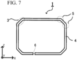
- FIG. 7 is a side view of the bent body 1 of the wound core 10 in FIG. 1 .
- the bent body 1 is obtained by bending a coated grain-oriented electrical steel sheet and includes four corner portions 3 and four flat portions 4, so that one coated grain-oriented electrical steel sheet forms a substantially rectangular ring in viewing from the side. More specifically, the bent body 1 has a structure in which one flat portion 4 is provided with a gap 6 in which both end surfaces in a longitudinal direction of the coated grain-oriented electrical steel sheet face each other, and the other three flat portions 4 do not include the gap 6.
- the wound core 10 may have a laminated structure having a substantially rectangular shape as a whole in viewing from the side.
- the wound core 10 may have a configuration in which two flat portions 4 include the gap 6 and the other two flat portions 4 do not include the gap 6.
- a bent body is formed of two coated grain-oriented electrical steel sheets.
- the length of the steel sheet and the position of the bent region are adjusted such that an outer circumferential length of a flat portion 4 of a bent body disposed inside is equal to an inner circumferential length of a flat portion 4 of a bent body disposed outside.
- the wound core producing apparatus 40 is a producing apparatus 40 for a wound core 10 formed by bending and laminating a steel sheet (coated grain-oriented electrical steel sheet) 21, and includes a bending device 20 that bends the coated grain-oriented electrical steel sheet 21, and a feed roll 60 that feeds the coated grain-oriented electrical steel sheet 21 to the bending device 20.
- the wound core producing apparatus 40 of the present disclosure may include a decoiler 50, a cutting device 70, a heating device 30, and a laminating device (not illustrated) that laminates bent bodies 1 to produce a wound core 10.
- the decoiler 50 unwinds the coated grain-oriented electrical steel sheet 21 from a coil 27 of the coated grain-oriented electrical steel sheet 21.
- the coated grain-oriented electrical steel sheet 21 unwound from the decoiler 50 is conveyed toward the feed roll 60.
- the heating device 30 heats the feed roll 60, the cutting device 70, the bending device 20, and the grain-oriented electrical steel sheet 21.
- the heating device is not particularly limited as long as it can heat the feed roll 60, the cutting device 70, the bending device 20, and the coated grain-oriented electrical steel sheet 21.
- Examples of the heating device 30 include an infrared furnace.
- the heating temperature is not limited as long as the temperature range of the portion to be the bent region 5 (bent region forming portion) of the bent body 1 can be set to 70°C or higher and 300°C or lower.
- the heating temperature (achieving temperature) of the bent region can be controlled by, for example, an output (furnace temperature, current value, etc.) of the heating device 30. It is a matter of course that these conditions vary depending on the steel sheet to be used, the heating device 30, and the like, and it is not intended to uniformly indicate and define quantitative conditions. Therefore, in the present disclosure, a heating state is defined by a temperature distribution obtained by temperature measurement described later.
- the temperature of the portion to be the bent region 5 of the bent body 1 is 70°C or higher.
- the temperature is preferably 100°C or higher, and more preferably 150°C or higher.
- the upper limit of the temperature of the bent region forming portion is preferably controlled to 300°C or lower.
- the heating device 30 can stably heat the portion to be the bent region 5 (bent region forming portion) of the bent body 1 in a temperature range of 70°C or higher and 300°C or lower. As a result, iron loss of the wound core 10 can be suppressed.
- the temperature of the bent region forming portion of the coated grain-oriented electrical steel sheet 21 in bending defined by the present disclosure is measured as follows.
- the temperature of the die 22 of the bending device 20 is measured by a thermocouple. Specifically, at a position of 20 mm in a direction opposite to the conveyance direction 25 of the coated grain-oriented electrical steel sheet 21 from an R-end of the die 22, thermocouples are installed at three locations that equally divide the entire width of the die 22 in a width direction of the die 22, and measurement is continuously performed by the thermocouples. Since the temperature of the die 22 and the temperature of the coated grain-oriented electrical steel sheet 21 are substantially equal, the temperature of the die 22 is regarded as the temperature of the bent region forming portion.
- the R-end refers to a boundary portion between a curved surface and a flat surface of the die 22. The average value of the obtained measured values is defined as the temperature of the bent region forming portion.
- the width direction of the die 22 is a direction corresponding to the width direction of the coated grain-oriented electrical steel sheet 21.
- the feed roll 60 conveys the coated grain-oriented electrical steel sheet 21 to the bending device 20.
- the feed roll 60 adjusts a conveyance direction 25 of the coated grain-oriented electrical steel sheet 21 immediately before being supplied into the bending device 20.
- the feed roll 60 adjusts the conveyance direction 25 of the coated grain-oriented electrical steel sheet 21 in a horizontal direction, and then supplies the coated grain-oriented electrical steel sheet 21 to the bending device 20.
- the Shore hardness of an outer circumferential surface of the feed roll 60 measured at 45°C is A38 or more and A90 or less.
- the outer circumferential surface is a surface in contact with the coated grain-oriented electrical steel sheet 21.
- the Shore hardness of the outer circumferential surface of the feed roll 60 measured at 45°C is A38 or more and A90 or less, the wound core can be stably produced even when the temperature of the feed roll 60 becomes 80°C or higher.
- the Shore hardness of the outer circumferential surface of the feed roll 60 at 150°C is A50 or more and A90 or less.
- the Shore hardness of the outer circumferential surface of the feed roll 60 at 270°C is A50 or more and A90 or less.
- the hardness (Shore hardness) of the outer circumferential surface of the feed roll 60 used for the outer circumferential surface of the feed roll 60 can be measured in accordance with JIS K6253-3: 2012.
- the relative humidity at the time of measurement is, for example, 45% to 53%.
- a type A durometer is used for measurement of the Shore hardness. The measurement is performed 3 seconds after pressurization.
- the material of the outer circumferential surface of the feed roll 60 is not particularly limited as long as the Shore hardness of the outer circumferential surface of the feed roll 60 measured at 45°C is A38 or more and A90 or less.
- Examples of the material of the outer circumferential surface of the feed roll 60 include rubber, polystyrene, polyvinyl chloride, and phenolic resin.
- the material of the outer circumferential surface of the feed roll 60 is preferably rubber.
- the rubber used for the outer circumferential surface of the feed roll 60 is, for example, one or more selected from the group consisting of diene-based rubber, olefin-based rubber, silicone rubber, and fluororubber.
- Examples of the diene-based rubber include styrene-butadiene rubber.
- Examples of the olefin-based rubber include ethylene propylene rubber and ethylene propylene diene rubber.
- Examples of the silicone rubber include dimethyl silicone rubber and methyl vinyl silicone rubber.
- Examples of the fluororubber include vinylidene fluoride-based rubber and tetrafluoroethylene-propylene-based fluororubber.
- Examples of the vinylidene fluoride-based rubber include propylene hexafluoride-vinylidene fluoride copolymers. The above rubbers may be used alone, or two or more kinds thereof may be mixed.
- the static friction coefficient of the outer circumferential surface of the feed roll 60 is preferably 0.07 to 0.92.
- the diameter of the feed roll 60 is 5 mm to 500 mm.
- the diameter of the feed roll is set to 5 mm to 500 mm, it is possible to stably produce a wound core in which iron loss is suppressed even when the temperature of the feed roll 60 becomes 80°C or higher.
- the pressure applied to the coated grain-oriented electrical steel sheet 21 by the feed roll 60 is 0.4 MPa to 2.4 MPa.
- the pressure is set to 0.4 MPa to 2.4 MPa, it is possible to stably produce a wound core in which iron loss is suppressed even when the temperature of the feed roll 60 becomes 80°C or higher.
- the surface temperature of the feed roll 60 is preferably 80°C or higher.
- the surface temperature of the feed roll is more preferably 90°C or higher.
- the upper limit of the surface temperature of the feed roll 60 is not particularly limited, but is 300°C or lower. More preferably, the surface temperature of the feed roll 60 is 260°C or lower.
- the surface temperature of the feed roll 60 can be measured using, for example, an infrared radiation thermometer.
- the conveyance speed of the coated grain-oriented electrical steel sheet 21 is preferably 5 m/min to 200 m/min. When the conveyance speed satisfies the above range, it is possible to more stably produce a wound core in which iron loss is suppressed.
- the cutting device 70 is installed between the feed roll 60 and the bending device 20.
- the coated grain-oriented electrical steel sheet 21 is cut by the cutting device 70, and then bent.
- the cutting method is not particularly limited.
- the cutting method is, for example, shearing.
- the bending device 20 bends the coated grain-oriented electrical steel sheet 21 conveyed from the feed roll 60.
- a bent body 1 has a bent region obtained by bending and a flat region adjacent to the bent region.
- a flat portion and a corner portion are alternately continuous.
- an angle formed by two adjacent flat portions is substantially 90°.
- the bending device 20 includes, for example, a die 22 and a punch 24 for press working.
- the bending device further includes a guide 23 for fixing the coated grain-oriented electrical steel sheet 21 and a cover (not illustrated).
- the cover covers the die 22, the punch 24, and the guide 23.
- the coated grain-oriented electrical steel sheet 21 is conveyed in the conveyance direction 25 and fixed at a position set in advance.
- the punch 24 pressurizes up to a predetermined position in a pressurization direction 26 with a predetermined force set in advance, so that the bent body 1 having a bent region of a desired bent angle ⁇ is obtained.
- a plurality of bent bodies 1 are laminated in a sheet thickness direction such that the coating of each bent body 1 is on an outer side.
- the bent bodies 1 are laminated by aligning corner portions 3 and being overlapped in a sheet thickness direction to form a laminated body 2 having a substantially rectangular shape in viewing from the side.
- the obtained wound core may be further fixed using a known binding band or fastening tool as necessary.
- the material of the outer circumferential surface of the feed roll 60 is rubber, the Shore hardness of the rubber measured at 45°C is A38 or more and A90 or less, the diameter of the feed roll 60 is 5 mm to 500 mm, and the pressure applied to the steel sheet by the feed roll 60 is 0.4 MPa to 2.4 MPa, it is possible to stably produce a wound core in which iron loss is suppressed even when the temperature of the feed roll becomes 80°C or higher.
- the present disclosure is not limited to the above embodiments.
- the above embodiments are examples, and anything having substantially the identical configuration as the technical idea described in the claims of the present disclosure and exhibiting the same operation and effects is included in the technical scope of the present disclosure.
- the wound core producing method according to the present disclosure produces a wound core using the above wound core producing apparatus.
- wound core producing apparatus is not limited to the following examples.
- the wound core producing apparatus according to the present disclosure can adopt various conditions as long as the object of the present disclosure is achieved without departing from the gist of the present disclosure.
- the conditions in the following examples are condition examples adopted to confirm the operability and effects.
- a glass coating (thickness: 1.0 ⁇ m) containing forsterite (Mg 2 SiO 4 ) as a primary coating and a secondary coating (thickness: 2.0 ⁇ m) containing aluminum phosphate were formed in this order on a base steel sheet (sheet thickness: 0.23 mm) having the above-described chemical composition to produce a coated grain-oriented electrical steel sheet.
- the feed roll, the cutting device, and the bending device were heated so that the temperature of bent region forming portions of these coated grain-oriented electrical steel sheets was room temperature (23°C) or a temperature range of 50°C to 300°C as shown in Tables 3 to 11, and bending was performed at a bent angle ⁇ of 45° under the conditions shown in Tables 3 to 11 to obtain a bent body having a bent region.
- the temperature of the bent region forming portions was measured by the above-described method.
- the temperature of the roll was measured at a position within 20 mm from the roll surface using infrared thermography.
- the pressing pressure of the roll is a pressure applied to the coated grain-oriented electrical steel sheet by the feed roll.
- L1 is a distance (distance between inner surface-side flat regions) parallel to an X-axis direction and between grain-oriented electrical steel sheets 21 parallel to each other on the innermost circumference of the wound core in a plane cross section including a center CL.
- L2 is a distance (distance between inner surface-side flat regions) parallel to a Z-axis direction and between grain-oriented electrical steel sheets 1 parallel to each other on the innermost circumference of the wound core in a longitudinal cross section including the center CL.
- L3 is a laminated thickness (thickness in the stacking direction) of the wound core in the plane cross section including the center CL and parallel to the X-axis direction.
- L4 is a width of the laminated steel sheet of the wound core in the plane cross section parallel to the X-axis direction and including the center CL.
- L5 is a distance between flat regions (distance between bent regions) disposed adjacent to each other in the innermost portion of the wound core and so as to form a right angle. In other words, L5 is a length in a longitudinal direction of a flat region having the shortest length among the flat regions of the grain-oriented electrical steel sheet on the innermost circumference.
- the wound core according to the present example has a structure in which a flat region whose inner surface-side flat region distance is L1 is divided at substantially a center of the distance L1, and two cores having a "substantially U-shaped" shape are coupled.
- L1 197 mm
- L2 66 mm
- L3 47 mm
- L4 152.4 mm
- L5 4 mm
- radius of curvature r 1 mm were set.
- the Shore hardness of the rubber used for the material of the outermost circumference of the feed roll was measured. As the sample, the rubbers in Table 1 were used. The Shore hardness of the rubber was measured in accordance with JIS K6253-3: 2012. The Shore hardness is obtained by adding A in front of the number in the column of Shore hardness In Table 1. For example, if the number in the column of Shore hardness in Table 1 is 40, the Shore hardness is A40. The measurement temperature was 23°C to 270°C. For measurement, a type A durometer was used. The obtained results are shown in Table 2. The relative humidity at the time of measurement was set to 45 to 53%. The measurement was performed 3 seconds after pressurization.
- Iron loss was evaluated in building factor.
- measurement using the excitation current method described in JIS C 2550-1 was performed under the conditions of a frequency of 50 Hz and a magnetic flux density of 1.7 T, and an iron loss value (core iron loss) W A of the wound core was measured.
- a sample having a width of 100 mm ⁇ a length of 500 mm was collected from a hoop (sheet width of 152.4 mm) of the grain-oriented electrical steel sheet used for the core, and this sample was subjected to measurement by an electrical steel sheet single sheet magnetic properties test using the H-coil method described in JIS C 2556 under the conditions of a frequency of 50 Hz and a magnetic flux density of 1.7 T to measure an iron loss value (iron loss of steel sheet) W B of the material steel sheet single sheet.
- Roll material No. Surface temperature of roll (°C) Temperature of bent region forming portion (°C) Diameter of roll (mm) Pressing pressure of roll (MPa) Building factor First wound core Second wound core Third wound core Fourth wound core 70 C 23 23 4 1.2 1.25 1.25 1.25 1.25 71 C 23 23 5 0 1.24 1.24 1.24 1.24 72 C 23 23 5 0.4 1.24 1.24 1.24 73 C 23 23 5 0.7 1.24 1.24 1.24 1.24 74 C 23 23 5 1.2 1.25 1.25 1.25 1.25 75 C 23 23 5 2.4 1.23 1.23 1.23 1.23 76 C 23 23 5 3.6 1.24 1.24 1.24 1.24 77 C 50 43 5 1.2 1.20 1.20 1.20 1.20 78 C 80 70 5 1.2 1.17 1.17 1.17 79 C 90 76 5 1.2 1.13 1.13 1.13 80 C 130 100 5 1.2 1.10 1.10 1.10 81 C 200 140 5 1.2 1.08 - - - 82 C 250 185 5 1.2 1.07
- Roll material No. Surface temperature of roll (°C) Temperature of bent region forming portion (°C) Diameter of roll (mm) Pressing pressure of roll (MPa) Building factor First wound core Second wound core Third wound core Fourth wound core 91 C 200 140 50 0.4 1.08 - - - 92 C 200 140 50 0.7 1.08 - - - 93 C 200 140 50 1.2 1.08 - - - 94 C 200 140 50 2.4 1.08 - - - 95 C 200 140 50 3.6 1.24 - - - 96 C 130 100 500 0 1.24 1.24 1.24 1.24 1.24 97 C 130 100 500 0.4 1.11 1.11 1.11 1.11 98 C 130 100 500 0.7 1.11 1.11 1.11 1.11 99 C 130 100 500 1.2 1.10 1.10 1.10 100 C 130 100 500 2.4 1.11 1.11 1.11 1.11 101 C 130 100 500 3.6 1.24 1.24 1.24 1.24 102 C 130 100 500 6.2 1.24 1.24 1.24 1.24 103 C 130 100 500 11 1.24 1.24 1.
- Roll material No. Surface temperature of roll (°C) Temperature of bent region forming portion (°C) Diameter of roll (mm) Pressing pressure of roll (MPa) Building factor First wound core Second wound core Third wound core Fourth wound core 116 D 23 23 4 1.2 1.25 1.25 1.25 1.25 117 D 23 23 5 0 1.24 1.24 1.24 1.24 118 D 23 23 5 0.4 1.24 1.24 1.24 1.24 119 D 23 23 5 0.7 1.24 1.24 1.24 1.24 120 D 23 23 5 1.2 1.25 1.25 1.25 1.25 121 D 23 23 5 2.4 1.23 1.23 1.23 122 D 23 23 5 3.6 1.24 1.24 1.24 1.24 123 D 50 45 5 1.2 1.20 1.20 1.20 1.20 124 D 80 70 5 1.2 1.17 1.17 1.17 125 D 90 85 5 1.2 1.13 1.13 1.13 126 D 130 110 5 1.2 1.09 1.09 1.09 127 D 200 170 5 1.2 1.06 1.06 1.06 1.06 128 D 250 200 5 1.2 1.
- Roll material No. Surface temperature of roll (°C) Temperature of bent region forming portion (°C) Diameter of roll (mm) Pressing pressure of roll (MPa) Building factor First wound core Second wound core Third wound core Fourth wound core 143 D 300 260 50 3.6 1.24 - - - 144 D 23 23 500 0 1.24 1.24 1.24 1.24 145 D 23 23 500 0.4 1.24 1.24 1.24 1.24 146 D 23 23 500 0.7 1.24 1.24 1.24 1.24 147 D 23 23 500 1.2 1.25 1.25 1.25 1.25 148 D 23 23 500 2.4 1.23 1.23 1.23 149 D 23 23 500 3.6 1.24 1.24 1.24 1.24 150 D 250 200 500 0 1.24 1.24 1.24 1.24 151 D 250 200 500 0.4 1.07 1.07 1.07 1.07 152 D 250 200 500 0.7 1.07 1.07 1.07 1.07 153 D 250 200 500 1.2 1.07 1.07 1.07 1.07 154 D 250 200 500 2.4 1.07 1.07 1.07 1.07 155 D 250 200 500 3.6 1.
- Roll material No. Surface temperature of roll (°C) Temperature of bent region forming portion (°C) Diameter of roll (mm) Pressing pressure of roll (MPa) Building factor First wound core Second wound core Third wound core Fourth wound core 299 H 200 140 50 0.4 1.08 - - - 300 H 200 140 50 0.7 1.08 - - - 301 H 200 140 50 1.2 1.08 - - - 302 H 200 140 50 2.4 1.08 - - - 303 H 200 140 50 3.6 1.24 - - - 304 H 130 100 500 0 1.24 1.24 1.24 1.24 305 H 130 100 500 0.4 1.11 1.11 1.11 1.11 306 H 130 100 500 0.7 1.11 1.11 1.11 1.11 307 H 130 100 500 1.2 1.11 1.11 1.11 1.11 308 H 130 100 500 2.4 1.11 1.11 1.11 1.11 309 H 130 100 500 3.6 1.25 1.24 1.24 1.24 310 H 130 100 500 6.2 1.24 1.25 1.24 1.25 311 H 130 100 500 11 1.25
- roll materials No. D and No. E which are rubbers having a Shore hardness at 270°C of A50 or more and 90 or less, it was possible to produce up to the fourth wound core even when the surface temperature of the feed roll was 250°C. In the case of using the roll material No. E, it was possible to produce up to the fourth wound core even when the surface temperature of the feed roll was 300°C.
Landscapes
- Engineering & Computer Science (AREA)
- Power Engineering (AREA)
- Manufacturing & Machinery (AREA)
- Soft Magnetic Materials (AREA)
- Manufacturing Cores, Coils, And Magnets (AREA)
- Manufacture Of Motors, Generators (AREA)
Abstract
Description
- The present invention relates to a wound core producing apparatus and a wound core producing method.
- The present application claims priority based on
Japanese Patent Application No. 2022-016395 filed in Japan on February 4, 2022 - A wound core is widely used as a magnetic core for a transformer, a reactor, a noise filter, or the like. Conventionally, reduction of iron loss occurring in a core has been one of important problems from the viewpoint of high efficiency and the like, and reduction of iron loss has been studied from various viewpoints.
- For example,
Patent Document 1 discloses the following wound core producing method. In this producing method, a coated grain-oriented electrical steel sheet having a coating containing phosphorus on a surface is bent into a bent body, and a plurality of bent bodies are laminated in a sheet thickness direction to produce a wound core. When bending the coated grain-oriented electrical steel sheet, the bending is performed in a state in which a portion to be a bent region of the bent body is set to 150°C or higher and 500°C or lower. The plurality of obtained bent bodies are laminated in the sheet thickness direction. According to such a method, the number of deformation twins in the bent region of the bent body is suppressed, and a wound core in which iron loss is suppressed is obtained. - For example, in the method of
Patent Document 2, the following wound core producing method is disclosed. In this producing method, a coated grain-oriented electrical steel sheet is prepared, and the coated grain-oriented electrical steel sheet is formed into the bent body. In the bending, the coated grain-oriented electrical steel sheet is bent under the condition that a portion to be the bent region of the bent body is heated to 45°C or higher and 500°C or lower and an absolute value of a local temperature gradient at an arbitrary position in a longitudinal direction of the coated grain-oriented electrical steel sheet is less than 400 °C/mm in a flat region in the strain influence region to form the bent body. The plurality of bent bodies are laminated in a sheet thickness direction. According to such a method, the number of deformation twins in the bent region is suppressed, and a wound core in which iron loss is suppressed is obtained. -
- [Patent Document 1]
PCT International Publication No. WO 2018/131613 - [Patent Document 2]
PCT International Publication No. WO 2020/218607 - However, in the wound core producing apparatuses disclosed in
Patent Documents - The present invention has been made in view of the above problem and provides a wound core producing apparatus and a wound core producing method capable of stably producing a wound core in which iron loss is suppressed.
- In order to solve the above problem, the present invention proposes the means described below.
- <1> A wound core producing apparatus according to
Aspect 1 of the present invention is a wound core producing apparatus, the wound core being formed by bending and laminating a steel sheet, the wound core producing apparatus including:- a bending device that bends the steel sheet; and
- a feed roll that feeds the steel sheet to the bending device,
- in which
- a diameter of the feed roll is 5 mm to 500 mm,
- a pressure applied to the steel sheet by the feed roll is 0.4 MPa to 2.4 MPa, and
- a Shore hardness of an outer circumferential surface of the feed roll measured at 45°C is A38 or more and A90 or less.
- <2> According to
Aspect 2 of the present invention, in the wound core producing apparatus according toAspect 1, a material of the outer circumferential surface of the feed roll may be rubber. - <3> According to
Aspect 3 of the present invention, in the wound core producing apparatus according toAspect 2, the rubber of the feed roll may be one or more selected from the group consisting of diene-based rubber, olefin-based rubber, silicone rubber, and fluororubber. - <4> In a wound core producing method according to
Aspect 4 of the present invention, a wound core is produced using the producing apparatus according to any one ofAspects 1 to 3. - According to the above aspects of the present invention, it is possible to provide a wound core producing apparatus and a wound core producing method capable of stably producing a wound core in which iron loss is suppressed.
-
-
FIG. 1 is a perspective view illustrating a wound core according to a first aspect. -
FIG. 2 is a side view of the wound core inFIG. 1 . -
FIG. 3 is a side view illustrating a wound core according to a second aspect. -
FIG. 4 is a side view illustrating a wound core according to a third aspect. -
FIG. 5 is an enlarged side view of the vicinity of a corner portion of the wound core inFIG. 1 . -
FIG. 6 is an enlarged side view of an example of a bent region. -
FIG. 7 is a side view of a bent body of the wound core inFIG. 1 . -
FIG. 8 is an explanatory view illustrating a first example of a wound core producing apparatus used in a wound core producing method. -
FIG. 9 is a schematic view illustrating dimensions of a wound core produced at the time of characteristic evaluation. - First, a wound core produced by a wound core producing apparatus according to an embodiment of the present invention will be described in detail. However, the present invention is not limited only to the configuration disclosed in the present embodiment, and various modifications can be made without departing from the gist of the present invention. Note that a numerical range described below includes the lower limit and the upper limit. A numerical value indicated as "more than" or "less than" is not included in the numerical range. In addition, unless otherwise specified, the unit "%" regarding the chemical composition means "mass%".
- Terms such as "parallel", "perpendicular", "identical", and "at right angle", values of length and angle, and the like, which specify shapes, geometric conditions, and degrees thereof, used in the present specification are not to be bound by a strict meaning but are to be interpreted including a range in which similar functions can be expected. In the present disclosure, substantially 90° allows an error of ±3°, and means a range of 87° to 93°.
- A wound core according to the present disclosure is a wound core formed by laminating, in a sheet thickness direction, a plurality of bent bodies formed from a coated grain-oriented electrical steel sheet, in which a coating is formed on at least one surface of the grain-oriented electrical steel sheet, such that the coating is on an outer side, in which the bent body has a bent region obtained by bending the coated grain-oriented electrical steel sheet, and a flat region adjacent to the bent region.
- The coated grain-oriented electrical steel sheet in the present disclosure includes at least a grain-oriented electrical steel sheet (sometimes referred to as a "base steel sheet" in the present disclosure) and a coating formed on at least one surface of the base steel sheet. The coated grain-oriented electrical steel sheet has at least a primary coating as the coating and may further have another layer as necessary. Examples of the other layer include a secondary coating provided on the primary coating.
- Hereinafter, the configuration of the coated grain-oriented electrical steel sheet will be described.
- In the coated grain-oriented electrical steel sheet constituting the
wound core 10 according to the present disclosure, the base steel sheet is a steel sheet in which the orientation of grains is highly accumulated in a {110}<001> orientation. The base steel sheet has excellent magnetic properties in a rolling direction. - The base steel sheet used for the wound core according to the present disclosure is not particularly limited. As the base steel sheet, a known grain-oriented electrical steel sheet can be appropriately selected and used. Hereinafter, an example of a preferable base steel sheet will be described, but the base steel sheet is not limited to the following example.
- The chemical composition of the base steel sheet is not particularly limited, but for example, it is preferable that the base steel sheet contains, in mass%, Si: 0.8% to 7%, C: more than 0% and 0.085% or less, acid-soluble Al: 0% to 0.065%, N: 0% to 0.012%, Mn: 0% to 1%, Cr: 0% to 0.3%, Cu: 0% to 0.4%, P: 0% to 0.5%, Sn: 0% to 0.3%, Sb: 0% to 0.3%, Ni: 0% to 1%, S: 0% to 0.015%, and Se: 0% to 0.015%, and the remainder is Fe and impurity elements.
- The above chemical composition of the base steel sheet is a preferred chemical component for controlling the crystal orientation to a Goss texture accumulated in the { 110}<001> orientation.
- Among the elements in the base steel sheet, Si and C are basic elements (essential elements) except Fe, and acid-soluble Al, N, Mn, Cr, Cu, P, Sn, Sb, Ni, S, and Se are selected elements (optional elements). Since these selected elements may be contained depending on the object, it is not necessary to limit the lower limit, and these selected elements may not be substantially contained. In addition, even if these selected elements are contained as impurity elements, the effects of the present disclosure are not impaired. The base steel sheet contains Fe and impurity elements as the remainder of the basic elements and the selected elements.
- However, when the Si content of the base steel sheet is 2.0% or more in mass%, classical eddy-current loss of the product is suppressed, which is preferable. The Si content of the base steel sheet is more preferably 3.0% or more. In addition, when the Si content of the base steel sheet is 5.0% or less in mass%, fracture of the steel sheet is less likely to occur in a hot rolling step and cold rolling, which is preferable. The Si content of the base steel sheet is more preferably 4.5% or less.
- The "impurity element" means an element unintentionally mixed from ore as a raw material, scrap, a producing environment, or the like when the base steel sheet is industrially produced.
- In addition, the grain-oriented electrical steel sheet generally undergoes purification annealing during secondary recrystallization. In the purification annealing, an inhibitor-forming element is discharged to the outside of the system. Particularly, for N and S, the concentration remarkably decreases to 50 ppm or less. Under normal purification annealing conditions, the concentration reaches 9 ppm or less, further 6 ppm or less, and a degree that cannot be detected by general analysis (1 ppm or less) if purification annealing is sufficiently performed.
- The chemical component of the base steel sheet may be measured by a general analysis method of steel. For example, the chemical component of the base steel sheet may be measured by inductively coupled plasma-atomic emission spectrometry (ICP-AES). Specifically, for example, the chemical component can be specified by acquiring a test piece of 35 mm square from a center position in a width direction of the base steel sheet after removal of a coating and performing measurement under a condition based on a calibration curve created in advance using ICPS-8100 produced by Shimadzu Corporation or the like (measurement apparatus). C and S may be measured by a combustion-infrared absorption method, and N may be measured by an inert gas fusion-thermal conductivity method.
- The chemical component of the base steel sheet is a component obtained by analyzing a component of a steel sheet obtained by removing a glass coating, a coating containing phosphorus, and the like described later from a grain-oriented electrical steel sheet by a method described later as the base steel sheet.
- The primary coating is a coating directly formed on a surface of a grain-oriented electrical steel sheet as a base steel sheet without any other layer or film, and examples thereof include a glass coating. Examples of the glass coating include a coating having one or more oxides selected from forsterite (Mg2SiO4), spinel (MgAl2O4), and cordierite (Mg2Al4Si5O16).
- The method for forming the glass coating is not particularly limited and can be appropriately selected from known methods. For example, a specific example of a method for producing the base steel sheet includes a method in which an annealing separator containing one or more selected from magnesia (MgO) and alumina (Al2O3) is applied to a cold-rolled steel sheet, and then finish annealing is performed. The annealing separator also has an effect of suppressing sticking of steel sheets during finish annealing. For example, when finish annealing is performed by applying the annealing separator containing magnesia, silica contained in the base steel sheet reacts with the annealing separator to form a glass coating containing forsterite (Mg2SiO4) on a base steel sheet surface.
- For example, a coating containing phosphorus described later may be formed as a primary coating without forming a glass film on a surface of a grain-oriented electrical steel sheet.
- The thickness of the primary coating is not particularly limited, but is preferably, for example, 0.5 µm or more and 3 µm or less from the viewpoint of forming the primary coating on the entire surface of a base steel sheet and suppressing peeling.
- The coated grain-oriented electrical steel sheet may include a coating other than the primary coating. For example, it is preferable that the coated grain-oriented electrical steel sheet have a coating containing phosphorus as a secondary coating on the primary coating mainly for imparting insulation properties. The coating containing phosphorus is a coating formed on the outermost surface of the grain-oriented electrical steel sheet, and when the grain-oriented electrical steel sheet has a glass coating or an oxide coating as a primary coating, the coating containing phosphorus is formed on the primary coating. By forming a coating containing phosphorus on the glass coating formed as a primary coating film on the surface of the base steel sheet, high adhesion can be secured.
- The coating containing phosphorus can be appropriately selected from conventionally known coatings. The coating containing phosphorus is preferably a phosphate-based coating, and particularly preferably a coating containing one or more of aluminum phosphate and magnesium phosphate as main components, and further containing one or more of chromium and silicon oxide as accessory components. According to the phosphate-based coating, insulation properties of the steel sheet are secured, and tension is imparted to the steel sheet to be excellent in reduction of iron loss.
- The thickness of the coating containing phosphorus is not particularly limited but is preferably 0.5 µm or more and 3 µm or less from the viewpoint of securing insulation properties.
- The sheet thickness of the coated grain-oriented electrical steel sheet is not particularly limited, and may be appropriately selected according to the application and the like, but is usually in the range of 0.10 mm to 0.50 mm, preferably 0.13 mm to 0.35 mm, and more preferably in the range of 0.15 mm to 0.30 mm.
- An example of a configuration of a wound core according to the present disclosure will be described with reference to a
wound core 10 inFIGS. 1 and 2 as an example.FIG. 1 is a perspective view of awound core 10, andFIG. 2 is a side view of thewound core 10 inFIG. 1 . - In the present disclosure, viewing from the side means viewing in a width direction (Y-axis direction in
FIG. 1 ) of a coated grain-oriented electrical steel sheet in a long shape constituting a wound core. The side view is a view illustrating a shape visually recognized by viewing from the side (a view in the Y-axis direction inFIG. 1 ). The sheet thickness direction is a sheet thickness direction of a coated grain-oriented electrical steel sheet, and means a direction perpendicular to a circumferential surface of a wound core in a state of being formed into a rectangular wound core. Here, the direction perpendicular to a circumferential surface means a direction perpendicular to the circumferential surface when the circumferential surface is viewed from the side. When the circumferential surface forms a curve in viewing the circumferential surface from the side, the direction perpendicular to the circumferential surface (sheet thickness direction) means a direction perpendicular to a tangent of the curve formed by the circumferential surface. - The
wound core 10 is configured by laminating a plurality ofbent bodies 1 in a sheet thickness direction thereof. That is, as illustrated inFIGS. 1 and 2 , thewound core 10 has a substantially rectangular laminated structure including a plurality ofbent bodies 1. Thewound core 10 may be used as it is as a wound core. If necessary, thewound core 10 may be fixed using a fastening tool such as a known binding band. Thebent body 1 is formed from a coated grain-oriented electrical steel sheet, in which a coating is formed on at least one surface of the grain-oriented electrical steel sheet as a base steel sheet. - As illustrated in
FIGS. 1 and 2 , each of thebent bodies 1 is formed in a rectangular shape by alternately continuing fourflat portions 4 and fourcorner portions 3 along a circumferential direction. An angle formed by twoflat portions 4 adjacent to eachcorner portion 3 is substantially 90°. Here, the circumferential direction means a direction around an axis of thewound core 10. - As illustrated in
FIG. 2 , in thewound core 10, each of thecorner portions 3 of thebent body 1 has twobent regions 5. Thebent region 5 is a region having a curved bent shape in viewing thebent body 1 from the side, and a more specific definition thereof will be described later. As will also be described later, in the twobent regions 5, bent angles in total are substantially 90° in viewing thebent body 1 from the side. - Each of the
corner portions 3 of thebent body 1 may have threebent regions 5 in onecorner portion 3 as in awound core 10A according to a second aspect of the present disclosure illustrated inFIG. 3 . Further, as in awound core 10B according to a third aspect illustrated inFIG. 4 , onecorner portion 3 may have onebent region 5. That is, each of thecorner portions 3 of thebent body 1 may have one or morebent regions 5 so that the steel sheet is bent by substantially 90°. - As illustrated in
FIG. 2 , thebent body 1 has aflat region 8 adjacent to abent region 5. As theflat region 8 adjacent to abent region 5, there are twoflat regions 8 shown in (1) and (2) below. - (1) A
flat region 8 positioned between abent region 5 and a bent region 5 (between twobent regions 5 adjacent in the circumferential direction) in onecorner portion 3 and adjacent to eachbent region 5. - (2) A
flat region 8 adjacent to eachbent region 5 as aflat portion 4. -
FIG. 5 is an enlarged side view of the vicinity of acorner portion 3 in thewound core 10 inFIG. 1 . - As illustrated in
FIG. 5 , when onecorner portion 3 has twobent regions bent region 5a (curved portion) is continuous from aflat portion 4a (straight portion) which is a flat region of thebent body 1, and further, aflat region 7a (straight portion), abent region 5b (curved portion), and aflat portion 4b (straight portion) which is a flat region are continuous therebeyond. - In the
wound core 10, a region from a line segment A-A' to a line segment B-B' inFIG. 5 is thecorner portion 3. A point A is an end point on aflat portion 4a side in thebent region 5a of thebent body 1a disposed on the innermost side of thewound core 10. A point A' is an intersection point of a straight line passing through the point A and perpendicular (sheet thickness direction) to a sheet surface of thebent body 1a and the outermost surface of the wound core 10 (an outer circumferential surface of thebent body 1 disposed on the outermost side of the wound core 10). Similarly, a point B is an end point on aflat portion 4b side in thebent region 5b of thebent body 1a disposed on the innermost side of thewound core 10. A point B' is an intersection point of a straight line passing through the point B and perpendicular (sheet thickness direction) to a sheet surface of thebent body 1a and the outermost surface of thewound core 10. InFIG. 5 , an angle formed by twoflat portions corner portion 3 interposed therebetween (angle formed by intersection of extension lines of theflat portions FIG. 5 , the θ is substantially 90°. The bent angles of thebent regions FIG. 5 , the bent angles in total ϕ1 + ϕ2 of thebent regions - The
bent region 5 will be described in more detail with reference toFIG. 6. FIG. 6 is an enlarged side view of an example of thebent region 5 of thebent body 1. The bent angle ϕ of thebent region 5 means an angular difference generated between a flat region on a rear side in a bending direction and a flat region on a front side in the bending direction in thebent region 5 of thebent body 1. Specifically, the bent angle ϕ of thebent region 5 is represented as an angle ϕ of a complementary angle of an angle formed by two imaginary lines Lb-elongation 1 and Lb-elongation 2 obtained by extending straight portions continuous to both sides (points F and G) of a curved portion included in a line Lb representing an outer surface of thebent body 1 in thebent region 5. - The bent angle of each
bent region 5 is substantially 90° or less, and the bent angles in total of all thebent regions 5 in onecorner portion 3 are substantially 90°. - In viewing the
bent body 1 from the side, when points D and E on a line La representing an inner surface of thebent body 1 and the points F and G on the line Lb representing the outer surface of thebent body 1 are defined as follows, thebent region 5 indicates a region surrounded by (1A) a line delimited by the point D and the point E on the line La representing the inner surface of thebent body 1, (2A) a line delimited by the point F and the point G on the line Lb representing the outer surface of thebent body 1, (3A) a straight line connecting the point D and the point G, and (4A) a straight line connecting the point E and the point F. - Here, the point D, the point E, the point F, and the point G are defined as follows.
- In viewing from the side, a point at which a straight line AB connecting a center point A of a radius of curvature in a curved portion included in the line La representing the inner surface of the
bent body 1 and an intersection point B of the two imaginary lines Lb-elongation 1 and Lb-elongation 2 obtained by extending straight portions adjacent to both sides of the curved portion included in the line Lb representing the outer surface of thebent body 1 intersects the line La representing the inner surface of thebent body 1 is defined as an origin C, - a point separated from the origin C by a distance m represented by the following formula (1) in one direction along the line La representing the inner surface of the
bent body 1 is defined as the point D, - a point separated from the origin C by the distance m in another direction along the line La representing the inner surface of the bent body is defined as the point E,
- an intersection point between a straight portion facing the point D among the straight portions included in the line Lb representing the outer surface of the bent body and an imaginary line drawn perpendicularly to the straight portion facing the point D and passing through the point D is defined as the point G, and
- an intersection point between a straight portion facing the point E among the straight portions included in the line Lb representing the outer surface of the bent body and an imaginary line drawn perpendicularly to the straight portion facing the point E and passing through the point E is defined as the point F. The intersection point A is an intersection point obtained by extending a line segment EF and a line segment DG inward on the opposite side of the point B.

- In formula (1), m represents a distance from the origin C, and r represents a distance (radius of curvature) from the center point A to the origin C. The radius of curvature r of the
bent body 1 disposed on an inner surface side of thewound core 10 is preferably, for example, 1 mm or more and 5 mm or less. -
FIG. 7 is a side view of thebent body 1 of thewound core 10 inFIG. 1 . As illustrated inFIG. 7 , thebent body 1 is obtained by bending a coated grain-oriented electrical steel sheet and includes fourcorner portions 3 and fourflat portions 4, so that one coated grain-oriented electrical steel sheet forms a substantially rectangular ring in viewing from the side. More specifically, thebent body 1 has a structure in which oneflat portion 4 is provided with agap 6 in which both end surfaces in a longitudinal direction of the coated grain-oriented electrical steel sheet face each other, and the other threeflat portions 4 do not include thegap 6. - However, the
wound core 10 may have a laminated structure having a substantially rectangular shape as a whole in viewing from the side. Thewound core 10 may have a configuration in which twoflat portions 4 include thegap 6 and the other twoflat portions 4 do not include thegap 6. In this case, a bent body is formed of two coated grain-oriented electrical steel sheets. - It is desirable to prevent generation of a gap between two adjacent layers in a sheet thickness direction at the time of producing the wound core. Therefore, in the two adjacent bent bodies, the length of the steel sheet and the position of the bent region are adjusted such that an outer circumferential length of a
flat portion 4 of a bent body disposed inside is equal to an inner circumferential length of aflat portion 4 of a bent body disposed outside. - Next, a wound core producing apparatus according to the present disclosure will be described. As illustrated in
FIG. 8 , the woundcore producing apparatus 40 is a producingapparatus 40 for awound core 10 formed by bending and laminating a steel sheet (coated grain-oriented electrical steel sheet) 21, and includes abending device 20 that bends the coated grain-orientedelectrical steel sheet 21, and afeed roll 60 that feeds the coated grain-orientedelectrical steel sheet 21 to thebending device 20. The woundcore producing apparatus 40 of the present disclosure may include adecoiler 50, a cuttingdevice 70, aheating device 30, and a laminating device (not illustrated) that laminatesbent bodies 1 to produce awound core 10. - The
decoiler 50 unwinds the coated grain-orientedelectrical steel sheet 21 from acoil 27 of the coated grain-orientedelectrical steel sheet 21. The coated grain-orientedelectrical steel sheet 21 unwound from thedecoiler 50 is conveyed toward thefeed roll 60. - The
heating device 30 heats thefeed roll 60, the cuttingdevice 70, the bendingdevice 20, and the grain-orientedelectrical steel sheet 21. The heating device is not particularly limited as long as it can heat thefeed roll 60, the cuttingdevice 70, the bendingdevice 20, and the coated grain-orientedelectrical steel sheet 21. Examples of theheating device 30 include an infrared furnace. - The heating temperature is not limited as long as the temperature range of the portion to be the bent region 5 (bent region forming portion) of the
bent body 1 can be set to 70°C or higher and 300°C or lower. The heating temperature (achieving temperature) of the bent region can be controlled by, for example, an output (furnace temperature, current value, etc.) of theheating device 30. It is a matter of course that these conditions vary depending on the steel sheet to be used, theheating device 30, and the like, and it is not intended to uniformly indicate and define quantitative conditions. Therefore, in the present disclosure, a heating state is defined by a temperature distribution obtained by temperature measurement described later. However, it is easy for a person skilled in the art who performs heat treatment of a steel sheet as a normal operation to reproduce a desired temperature state in a practical range according to the steel sheet to be used and theheating device 30 based on measurement data of steel sheet temperature as described later, and such control does not hinder implementation of the wound core and the producing method thereof of the present disclosure. - When the temperature of the portion to be the
bent region 5 of thebent body 1 is lower than 70°C, it is impossible to suppress iron loss due to generation of deformation twins in thebent region 5. Therefore, the temperature of the portion to be thebent region 5 of thebent body 1 is 70°C or higher. The temperature is preferably 100°C or higher, and more preferably 150°C or higher. In addition, when the temperature of the portion to be thebent region 5 of thebent body 1 exceeds 300°C, the magnetic domain control effect may be lost. Therefore, the upper limit of the temperature of the bent region forming portion is preferably controlled to 300°C or lower. By heating thefeed roll 60, the cuttingdevice 70, the bendingdevice 20, and the coated grain-orientedelectrical steel sheet 21, theheating device 30 can stably heat the portion to be the bent region 5 (bent region forming portion) of thebent body 1 in a temperature range of 70°C or higher and 300°C or lower. As a result, iron loss of thewound core 10 can be suppressed. - Here, the temperature of the bent region forming portion of the coated grain-oriented
electrical steel sheet 21 in bending defined by the present disclosure is measured as follows. - As the temperature, for example, the temperature of the
die 22 of thebending device 20 is measured by a thermocouple. Specifically, at a position of 20 mm in a direction opposite to theconveyance direction 25 of the coated grain-orientedelectrical steel sheet 21 from an R-end of the die 22, thermocouples are installed at three locations that equally divide the entire width of the die 22 in a width direction of the die 22, and measurement is continuously performed by the thermocouples. Since the temperature of thedie 22 and the temperature of the coated grain-orientedelectrical steel sheet 21 are substantially equal, the temperature of the die 22 is regarded as the temperature of the bent region forming portion. The R-end refers to a boundary portion between a curved surface and a flat surface of thedie 22. The average value of the obtained measured values is defined as the temperature of the bent region forming portion. The width direction of the die 22 is a direction corresponding to the width direction of the coated grain-orientedelectrical steel sheet 21. - The
feed roll 60 conveys the coated grain-orientedelectrical steel sheet 21 to thebending device 20. Thefeed roll 60 adjusts aconveyance direction 25 of the coated grain-orientedelectrical steel sheet 21 immediately before being supplied into thebending device 20. Thefeed roll 60 adjusts theconveyance direction 25 of the coated grain-orientedelectrical steel sheet 21 in a horizontal direction, and then supplies the coated grain-orientedelectrical steel sheet 21 to thebending device 20. - The Shore hardness of an outer circumferential surface of the
feed roll 60 measured at 45°C is A38 or more and A90 or less. The outer circumferential surface is a surface in contact with the coated grain-orientedelectrical steel sheet 21. When the Shore hardness of the outer circumferential surface of thefeed roll 60 measured at 45°C is A38 or more and A90 or less, the wound core can be stably produced even when the temperature of thefeed roll 60 becomes 80°C or higher. More preferably, the Shore hardness of the outer circumferential surface of thefeed roll 60 at 150°C is A50 or more and A90 or less. Still more preferably, the Shore hardness of the outer circumferential surface of thefeed roll 60 at 270°C is A50 or more and A90 or less. - The hardness (Shore hardness) of the outer circumferential surface of the
feed roll 60 used for the outer circumferential surface of thefeed roll 60 can be measured in accordance with JIS K6253-3: 2012. The relative humidity at the time of measurement is, for example, 45% to 53%. For measurement of the Shore hardness, a type A durometer is used. The measurement is performed 3 seconds after pressurization. - The material of the outer circumferential surface of the
feed roll 60 is not particularly limited as long as the Shore hardness of the outer circumferential surface of thefeed roll 60 measured at 45°C is A38 or more and A90 or less. Examples of the material of the outer circumferential surface of thefeed roll 60 include rubber, polystyrene, polyvinyl chloride, and phenolic resin. The material of the outer circumferential surface of thefeed roll 60 is preferably rubber. - The rubber used for the outer circumferential surface of the
feed roll 60 is, for example, one or more selected from the group consisting of diene-based rubber, olefin-based rubber, silicone rubber, and fluororubber. - Examples of the diene-based rubber include styrene-butadiene rubber. Examples of the olefin-based rubber include ethylene propylene rubber and ethylene propylene diene rubber. Examples of the silicone rubber include dimethyl silicone rubber and methyl vinyl silicone rubber. Examples of the fluororubber include vinylidene fluoride-based rubber and tetrafluoroethylene-propylene-based fluororubber. Examples of the vinylidene fluoride-based rubber include propylene hexafluoride-vinylidene fluoride copolymers. The above rubbers may be used alone, or two or more kinds thereof may be mixed.
- The static friction coefficient of the outer circumferential surface of the
feed roll 60 is preferably 0.07 to 0.92. - The diameter of the
feed roll 60 is 5 mm to 500 mm. When the diameter of the feed roll is set to 5 mm to 500 mm, it is possible to stably produce a wound core in which iron loss is suppressed even when the temperature of thefeed roll 60 becomes 80°C or higher. - The pressure applied to the coated grain-oriented
electrical steel sheet 21 by thefeed roll 60 is 0.4 MPa to 2.4 MPa. When the pressure is set to 0.4 MPa to 2.4 MPa, it is possible to stably produce a wound core in which iron loss is suppressed even when the temperature of thefeed roll 60 becomes 80°C or higher. - The surface temperature of the
feed roll 60 is preferably 80°C or higher. The surface temperature of the feed roll is more preferably 90°C or higher. The upper limit of the surface temperature of thefeed roll 60 is not particularly limited, but is 300°C or lower. More preferably, the surface temperature of thefeed roll 60 is 260°C or lower. The surface temperature of thefeed roll 60 can be measured using, for example, an infrared radiation thermometer. - The conveyance speed of the coated grain-oriented
electrical steel sheet 21 is preferably 5 m/min to 200 m/min. When the conveyance speed satisfies the above range, it is possible to more stably produce a wound core in which iron loss is suppressed. - The cutting
device 70 is installed between thefeed roll 60 and thebending device 20. The coated grain-orientedelectrical steel sheet 21 is cut by the cuttingdevice 70, and then bent. The cutting method is not particularly limited. The cutting method is, for example, shearing. - The bending
device 20 bends the coated grain-orientedelectrical steel sheet 21 conveyed from thefeed roll 60. Abent body 1 has a bent region obtained by bending and a flat region adjacent to the bent region. In thebent body 1, a flat portion and a corner portion are alternately continuous. In each corner portion, an angle formed by two adjacent flat portions is substantially 90°. - The bending
device 20 includes, for example, adie 22 and apunch 24 for press working. The bending device further includes aguide 23 for fixing the coated grain-orientedelectrical steel sheet 21 and a cover (not illustrated). The cover covers thedie 22, thepunch 24, and theguide 23. After thebending device 20 bends the coated grain-orientedelectrical steel sheet 21, the coated grain-orientedelectrical steel sheet 21 may be cut by the cuttingdevice 70. After thecutting device 70 cuts the coated grain-orientedelectrical steel sheet 21, the bendingdevice 20 may perform bending. - The coated grain-oriented
electrical steel sheet 21 is conveyed in theconveyance direction 25 and fixed at a position set in advance. Next, thepunch 24 pressurizes up to a predetermined position in apressurization direction 26 with a predetermined force set in advance, so that thebent body 1 having a bent region of a desired bent angle ϕ is obtained. - A plurality of
bent bodies 1 are laminated in a sheet thickness direction such that the coating of eachbent body 1 is on an outer side. Thebent bodies 1 are laminated by aligningcorner portions 3 and being overlapped in a sheet thickness direction to form alaminated body 2 having a substantially rectangular shape in viewing from the side. As a result, it is possible to obtain the wound core having low iron loss according to the present disclosure. The obtained wound core may be further fixed using a known binding band or fastening tool as necessary. - As described above, since in the wound
core producing apparatus 40 according to the present disclosure, the material of the outer circumferential surface of thefeed roll 60 is rubber, the Shore hardness of the rubber measured at 45°C is A38 or more and A90 or less, the diameter of thefeed roll 60 is 5 mm to 500 mm, and the pressure applied to the steel sheet by thefeed roll 60 is 0.4 MPa to 2.4 MPa, it is possible to stably produce a wound core in which iron loss is suppressed even when the temperature of the feed roll becomes 80°C or higher. - The present disclosure is not limited to the above embodiments. The above embodiments are examples, and anything having substantially the identical configuration as the technical idea described in the claims of the present disclosure and exhibiting the same operation and effects is included in the technical scope of the present disclosure. The wound core producing method according to the present disclosure produces a wound core using the above wound core producing apparatus.
- Hereinafter, examples (experimental examples) will be described, but the wound core producing apparatus according to the present disclosure is not limited to the following examples. The wound core producing apparatus according to the present disclosure can adopt various conditions as long as the object of the present disclosure is achieved without departing from the gist of the present disclosure. The conditions in the following examples are condition examples adopted to confirm the operability and effects.
- A glass coating (thickness: 1.0 µm) containing forsterite (Mg2SiO4) as a primary coating and a secondary coating (thickness: 2.0 µm) containing aluminum phosphate were formed in this order on a base steel sheet (sheet thickness: 0.23 mm) having the above-described chemical composition to produce a coated grain-oriented electrical steel sheet.
- The feed roll, the cutting device, and the bending device were heated so that the temperature of bent region forming portions of these coated grain-oriented electrical steel sheets was room temperature (23°C) or a temperature range of 50°C to 300°C as shown in Tables 3 to 11, and bending was performed at a bent angle ϕ of 45° under the conditions shown in Tables 3 to 11 to obtain a bent body having a bent region. The temperature of the bent region forming portions was measured by the above-described method. The temperature of the roll was measured at a position within 20 mm from the roll surface using infrared thermography.
- The pressing pressure of the roll is a pressure applied to the coated grain-oriented electrical steel sheet by the feed roll.
- Subsequently, the bent body was laminated in a sheet thickness direction to obtain a wound core having dimensions shown in
FIG. 9 . L1 is a distance (distance between inner surface-side flat regions) parallel to an X-axis direction and between grain-orientedelectrical steel sheets 21 parallel to each other on the innermost circumference of the wound core in a plane cross section including a center CL. L2 is a distance (distance between inner surface-side flat regions) parallel to a Z-axis direction and between grain-orientedelectrical steel sheets 1 parallel to each other on the innermost circumference of the wound core in a longitudinal cross section including the center CL. L3 is a laminated thickness (thickness in the stacking direction) of the wound core in the plane cross section including the center CL and parallel to the X-axis direction. L4 is a width of the laminated steel sheet of the wound core in the plane cross section parallel to the X-axis direction and including the center CL. L5 is a distance between flat regions (distance between bent regions) disposed adjacent to each other in the innermost portion of the wound core and so as to form a right angle. In other words, L5 is a length in a longitudinal direction of a flat region having the shortest length among the flat regions of the grain-oriented electrical steel sheet on the innermost circumference. r is a radius of curvature of a bent region on an inner surface side of the wound core, and ϕ is a bent angle of a bent region of the wound core. The wound core according to the present example has a structure in which a flat region whose inner surface-side flat region distance is L1 is divided at substantially a center of the distance L1, and two cores having a "substantially U-shaped" shape are coupled. In each example, L1: 197 mm, L2: 66 mm, L3: 47 mm, L4: 152.4 mm, L5: 4 mm, and radius of curvature r: 1 mm were set. - The Shore hardness of the rubber used for the material of the outermost circumference of the feed roll was measured. As the sample, the rubbers in Table 1 were used. The Shore hardness of the rubber was measured in accordance with JIS K6253-3: 2012. The Shore hardness is obtained by adding A in front of the number in the column of Shore hardness In Table 1. For example, if the number in the column of Shore hardness in Table 1 is 40, the Shore hardness is A40. The measurement temperature was 23°C to 270°C. For measurement, a type A durometer was used. The obtained results are shown in Table 2. The relative humidity at the time of measurement was set to 45 to 53%. The measurement was performed 3 seconds after pressurization.
- Iron loss was evaluated in building factor. In measurement of the building factor, for each wound core produced under the conditions of Tables 3 to 11, measurement using the excitation current method described in JIS C 2550-1 was performed under the conditions of a frequency of 50 Hz and a magnetic flux density of 1.7 T, and an iron loss value (core iron loss) WA of the wound core was measured. In addition, a sample having a width of 100 mm × a length of 500 mm was collected from a hoop (sheet width of 152.4 mm) of the grain-oriented electrical steel sheet used for the core, and this sample was subjected to measurement by an electrical steel sheet single sheet magnetic properties test using the H-coil method described in JIS C 2556 under the conditions of a frequency of 50 Hz and a magnetic flux density of 1.7 T to measure an iron loss value (iron loss of steel sheet) WB of the material steel sheet single sheet.
- Then, the building factor (BF) was obtained by dividing the iron loss value WA by the iron loss value WB. The case where BF was 1.19 or less was regarded as acceptable. The results are shown in Tables 3 to 11. "-" in Tables 3 to 11 means that the feed roll was damaged and the wound core could not be produced.
[Table 1A] Roll material No. A B C D Rubber type Urethane rubber Styrene-butadiene rubber Ethylene propylene rubber Silicone rubber Chemical structure Polyurethane Butadiene-Styrene copolymer Ethylene propylene copolymer (ternary copolymer) Polysiloxane Static friction coefficient with coated grain-oriented electrical steel sheet 0.47 0.07 0.72 0.92 [Table 1B] Roll material No. E F G H I Rubber type Fluororubber Styrene-butadiene rubber Styrol resin Soft PVC Bakelite Chemical structure Propylene hexafluoride-vinylidene fluoride copolymer Butadiene-styrene copolymer Polystyrene Polyvinyl chloride Phenolic resin Static friction coefficient with coated grain-oriented electrical steel sheet 0.64 0.07 0.72 0.34 0.12 [Table 2] Roll material No. A B C D E F G H I Temperature (°C) Shore hardness 28 40 80 76 90 70 32 67 58 90 45 37 75 75 90 70 28 62 56 90 80 21 60 70 81 70 20 57 49 86 110 15 55 62 76 70 16 52 44 80 150 12 47 50 72 70 12 48 41 62 270 10 40 38 66 65 10 39 38 43 [Table 3] Experiment No. Roll material No. Surface temperature of roll (°C) Temperature of bent region forming portion (°C) Diameter of roll (mm) Pressing pressure of roll (MPa) Building factor First wound core Second wound core Third wound core Fourth wound core 1 A 23 23 30 0.4 1.24 1.24 1.24 1.24 2 A 50 43 30 0.4 1.21 1.21 1.21 1.21 3 A 70 55 30 0.4 1.20 1.20 1.20 1.20 4 A 80 64 30 0.4 1.15 1.15 1.15 - 5 A 130 100 30 0.4 1.10 1.10 - - 6 A 200 140 30 0.4 1.08 - - - 7 A 250 185 30 0.4 1.07 - - - 8 A 300 210 30 0.4 1.05 - - - [Table 4A] Experiment No. Roll material No. Surface temperature of roll (°C) Temperature of bent region forming portion (°C) Diameter of roll (mm) Pressing pressure of roll (MPa) Building factor First wound core Second wound core Third wound core Fourth wound core 9 B 23 23 4 1.2 1.25 1.25 1.25 1.25 10 B 23 23 5 0 1.24 1.24 1.24 1.24 11 B 23 23 5 0.4 1.24 1.24 1.24 1.24 12 B 23 23 5 0.7 1.24 1.24 1.24 1.24 13 B 23 23 5 1.2 1.25 1.25 1.25 1.25 14 B 23 23 5 2.4 1.23 1.23 1.23 1.23 15 B 23 23 5 3.6 1.24 1.24 1.24 1.24 16 B 70 55 5 1.2 1.20 1.20 1.20 1.20 17 B 80 70 5 1.2 1.15 1.15 1.15 1.15 18 B 130 95 5 1.2 1.10 1.10 - - 19 B 200 140 5 1.2 1.08 - - - 20 B 250 180 5 1.2 1.07 - - - 21 B 300 210 5 1.2 1.05 - - - 22 B 80 70 50 0 1.24 1.24 1.24 1.24 23 B 80 70 50 0.4 1.15 1.15 1.15 1.15 24 B 80 70 50 0.7 1.15 1.15 1.15 1.15 25 B 80 70 50 1.2 1.15 1.15 1.15 1.15 26 B 80 70 50 2.4 1.15 1.15 1.15 1.15 27 B 80 70 50 3.6 1.24 1.24 1.24 1.24 28 B 130 95 50 0 1.24 1.24 - - 29 B 130 95 50 0.4 1.11 1.11 - - 30 B 130 95 50 0.7 1.11 1.11 - - 31 B 130 95 50 1.2 1.10 1.10 - - 32 B 130 95 50 2.4 1.11 1.11 - - 33 B 130 95 50 3.6 1.23 1.24 - - 34 B 200 140 50 0 1.24 - - - 35 B 200 140 50 0.4 1.08 - - - 36 B 200 140 50 0.7 1.08 - - - 37 B 200 140 50 1.2 1.08 - - - 38 B 200 140 50 2.4 1.08 - - - 39 B 200 140 50 3.6 1.24 - - - [Table 4B] Experiment No. Roll material No. Surface temperature of roll (°C) Temperature of bent region forming portion (°C) Diameter of roll (mm) Pressing pressure of roll (MPa) Building factor First wound core Second wound core Third wound core Fourth wound core 40 B 23 23 500 0 1.24 1.24 1.24 1.24 41 B 23 23 500 0.4 1.24 1.24 1.24 1.24 42 B 23 23 500 0.7 1.24 1.24 1.24 1.24 43 B 23 23 500 1.2 1.25 1.25 1.25 1.25 44 B 23 23 500 2.4 1.23 1.23 1.23 1.23 45 B 23 23 500 3.6 1.24 1.24 1.24 1.24 46 B 80 70 500 0 1.24 1.24 1.24 1.24 47 B 80 70 500 0.4 1.15 1.15 1.15 1.15 48 B 80 70 500 0.7 1.15 1.15 1.15 1.15 49 B 80 70 500 1.2 1.15 1.15 1.15 1.15 50 B 80 70 500 2.4 1.15 1.15 1.15 1.15 51 B 80 70 500 3.6 1.24 1.24 1.24 1.24 52 B 130 95 500 0 1.24 1.24 - - 53 B 130 95 500 0.4 1.11 1.11 - - 54 B 130 95 500 0.7 1.11 1.11 - - 55 B 130 95 500 1.2 1.10 1.10 - - 56 B 130 95 500 2.4 1.11 1.11 - - 57 B 130 95 500 3.6 1.24 1.24 - - 58 B 200 140 500 0 1.24 - - - 59 B 200 140 500 0.4 1.08 - - - 60 B 200 140 500 0.7 1.08 - - - 61 B 200 140 500 1.2 1.08 - - - 62 B 200 140 500 2.4 1.08 - - - 63 B 200 140 500 3.6 1.24 - - - 64 B 80 70 600 0 1.23 1.23 1.23 1.23 65 B 80 70 600 0.4 1.23 1.23 1.23 1.23 66 B 80 70 600 0.7 1.23 1.23 1.23 1.23 67 B 80 70 600 1.2 1.23 1.23 1.23 1.23 68 B 80 70 600 2.4 1.23 1.23 1.23 1.23 69 B 80 70 600 3.6 1.23 1.23 1.23 1.23 [Table 5A] Experiment No. Roll material No. Surface temperature of roll (°C) Temperature of bent region forming portion (°C) Diameter of roll (mm) Pressing pressure of roll (MPa) Building factor First wound core Second wound core Third wound core Fourth wound core 70 C 23 23 4 1.2 1.25 1.25 1.25 1.25 71 C 23 23 5 0 1.24 1.24 1.24 1.24 72 C 23 23 5 0.4 1.24 1.24 1.24 1.24 73 C 23 23 5 0.7 1.24 1.24 1.24 1.24 74 C 23 23 5 1.2 1.25 1.25 1.25 1.25 75 C 23 23 5 2.4 1.23 1.23 1.23 1.23 76 C 23 23 5 3.6 1.24 1.24 1.24 1.24 77 C 50 43 5 1.2 1.20 1.20 1.20 1.20 78 C 80 70 5 1.2 1.17 1.17 1.17 1.17 79 C 90 76 5 1.2 1.13 1.13 1.13 1.13 80 C 130 100 5 1.2 1.10 1.10 1.10 1.10 81 C 200 140 5 1.2 1.08 - - - 82 C 250 185 5 1.2 1.07 - - - 83 C 300 210 5 1.2 1.05 - - - 84 C 130 100 50 0 1.24 1.24 1.24 1.24 85 C 130 100 50 0.4 1.11 1.11 1.11 1.11 86 C 130 100 50 0.7 1.11 1.11 1.11 1.11 87 C 130 100 50 1.2 1.10 1.10 1.10 1.10 88 C 130 100 50 2.4 1.11 1.11 1.11 1.11 89 C 130 100 50 3.6 1.24 1.24 1.24 1.24 90 C 200 140 50 0 1.24 - - - [Table 5B] Experiment No. Roll material No. Surface temperature of roll (°C) Temperature of bent region forming portion (°C) Diameter of roll (mm) Pressing pressure of roll (MPa) Building factor First wound core Second wound core Third wound core Fourth wound core 91 C 200 140 50 0.4 1.08 - - - 92 C 200 140 50 0.7 1.08 - - - 93 C 200 140 50 1.2 1.08 - - - 94 C 200 140 50 2.4 1.08 - - - 95 C 200 140 50 3.6 1.24 - - - 96 C 130 100 500 0 1.24 1.24 1.24 1.24 97 C 130 100 500 0.4 1.11 1.11 1.11 1.11 98 C 130 100 500 0.7 1.11 1.11 1.11 1.11 99 C 130 100 500 1.2 1.10 1.10 1.10 1.10 100 C 130 100 500 2.4 1.11 1.11 1.11 1.11 101 C 130 100 500 3.6 1.24 1.24 1.24 1.24 102 C 130 100 500 6.2 1.24 1.24 1.24 1.24 103 C 130 100 500 11 1.24 1.24 1.24 1.24 104 C 200 140 500 0 1.24 - - - 105 C 200 140 500 0.4 1.08 - - - 106 C 200 140 500 0.7 1.08 - - - 107 C 200 140 500 1.2 1.08 - - - 108 C 200 140 500 2.4 1.08 - - - 109 C 200 140 500 3.6 1.24 - - - 110 C 130 100 600 0 1.24 1.24 1.24 1.24 111 C 130 100 600 0.4 1.24 1.24 1.24 1.24 112 C 130 100 600 0.7 1.24 1.24 1.24 1.24 113 C 130 100 600 1.2 1.24 1.24 1.24 1.24 114 C 130 100 600 2.4 1.24 1.24 1.24 1.24 115 C 130 100 600 3.6 1.24 1.24 1.24 1.24 [Table 6A] Experiment No. Roll material No. Surface temperature of roll (°C) Temperature of bent region forming portion (°C) Diameter of roll (mm) Pressing pressure of roll (MPa) Building factor First wound core Second wound core Third wound core Fourth wound core 116 D 23 23 4 1.2 1.25 1.25 1.25 1.25 117 D 23 23 5 0 1.24 1.24 1.24 1.24 118 D 23 23 5 0.4 1.24 1.24 1.24 1.24 119 D 23 23 5 0.7 1.24 1.24 1.24 1.24 120 D 23 23 5 1.2 1.25 1.25 1.25 1.25 121 D 23 23 5 2.4 1.23 1.23 1.23 1.23 122 D 23 23 5 3.6 1.24 1.24 1.24 1.24 123 D 50 45 5 1.2 1.20 1.20 1.20 1.20 124 D 80 70 5 1.2 1.17 1.17 1.17 1.17 125 D 90 85 5 1.2 1.13 1.13 1.13 1.13 126 D 130 110 5 1.2 1.09 1.09 1.09 1.09 127 D 200 170 5 1.2 1.06 1.06 1.06 1.06 128 D 250 200 5 1.2 1.07 1.07 1.07 1.07 129 D 300 260 5 1.2 1.05 - - - 130 D 250 200 50 0 1.24 1.24 1.24 1.24 131 D 250 200 50 0.4 1.07 1.07 1.07 1.07 132 D 250 200 50 0.7 1.07 1.07 1.07 1.07 133 D 250 200 50 1.2 1.07 1.07 1.07 1.07 134 D 250 200 50 2.4 1.07 1.07 1.07 1.07 135 D 250 200 50 3.6 1.24 1.24 1.24 1.24 136 D 250 200 50 6.2 1.24 1.24 1.24 1.24 137 D 250 200 50 11 1.24 1.24 1.24 1.24 138 D 300 260 50 0 1.24 - - - 139 D 300 260 50 0.4 1.05 - - - 140 D 300 260 50 0.7 1.05 - - - 141 D 300 260 50 1.2 1.05 - - - 142 D 300 260 50 2.4 1.05 - - - [Table 6B] Experiment No. Roll material No. Surface temperature of roll (°C) Temperature of bent region forming portion (°C) Diameter of roll (mm) Pressing pressure of roll (MPa) Building factor First wound core Second wound core Third wound core Fourth wound core 143 D 300 260 50 3.6 1.24 - - - 144 D 23 23 500 0 1.24 1.24 1.24 1.24 145 D 23 23 500 0.4 1.24 1.24 1.24 1.24 146 D 23 23 500 0.7 1.24 1.24 1.24 1.24 147 D 23 23 500 1.2 1.25 1.25 1.25 1.25 148 D 23 23 500 2.4 1.23 1.23 1.23 1.23 149 D 23 23 500 3.6 1.24 1.24 1.24 1.24 150 D 250 200 500 0 1.24 1.24 1.24 1.24 151 D 250 200 500 0.4 1.07 1.07 1.07 1.07 152 D 250 200 500 0.7 1.07 1.07 1.07 1.07 153 D 250 200 500 1.2 1.07 1.07 1.07 1.07 154 D 250 200 500 2.4 1.07 1.07 1.07 1.07 155 D 250 200 500 3.6 1.24 1.24 1.24 1.24 156 D 300 260 500 0 1.24 - - - 157 D 300 260 500 0.4 1.05 - - - 158 D 300 260 500 0.7 1.05 - - - 159 D 300 260 500 1.2 1.05 - - - 160 D 300 260 500 2.4 1.05 - - - 161 D 300 260 500 3.6 1.24 - - - 162 D 250 200 600 0 1.24 1.24 1.24 1.24 163 D 250 200 600 0.4 1.24 1.24 1.24 1.24 164 D 250 200 600 0.7 1.24 1.24 1.24 1.24 165 D 250 200 600 1.2 1.24 1.24 1.24 1.24 166 D 250 200 600 2.4 1.24 1.24 1.24 1.24 167 D 250 200 600 3.6 1.24 1.24 1.24 1.24 168 D 300 260 600 0 1.24 - - - 169 D 300 260 600 0.4 1.24 - - - 170 D 300 260 600 0.7 1.24 - - - 171 D 300 260 600 1.2 1.24 - - - 172 D 300 260 600 2.4 1.24 - - - 173 D 300 260 600 3.6 1.24 - - - [Table 7] Experiment No. Roll material No. Surface temperature of roll (°C) Temperature of bent region forming portion (°C) Diameter of roll (mm) Pressing pressure of roll (MPa) Building factor First wound core Second wound core Third wound core Fourth wound core 174 E 23 23 4 1.2 1.25 1.25 1.25 1.25 175 E 23 23 5 0 1.24 1.24 1.24 1.24 176 E 23 23 5 0.4 1.24 1.24 1.24 1.24 177 E 23 23 5 0.7 1.24 1.24 1.24 1.24 178 E 23 23 5 1.2 1.25 1.25 1.25 1.25 179 E 23 23 5 2.4 1.23 1.23 1.23 1.23 180 E 23 23 5 3.6 1.24 1.24 1.24 1.24 181 E 50 45 5 1.2 1.20 1.20 1.20 1.20 182 E 80 70 5 1.2 1.17 1.17 1.17 1.17 183 E 90 85 5 1.2 1.13 1.13 1.13 1.13 184 E 130 110 5 1.2 1.09 1.09 1.09 1.09 185 E 200 170 5 1.2 1.06 1.06 1.06 1.06 186 E 250 200 5 1.2 1.05 1.07 1.07 1.07 187 E 300 260 5 1.2 1.03 1.03 1.03 1.03 188 E 300 260 50 0 1.24 1.24 1.24 1.24 189 E 300 260 50 0.4 1.02 1.02 1.02 1.02 190 E 300 260 50 0.7 1.03 1.03 1.03 1.03 191 E 300 260 50 1.2 1.03 1.03 1.03 1.03 192 E 300 260 50 2.4 1.02 1.02 1.02 1.02 193 E 300 260 50 3.6 1.24 1.24 1.24 1.24 194 E 300 260 500 0 1.24 1.24 1.24 1.24 195 E 300 260 500 0.4 1.02 1.02 1.02 1.02 196 E 300 260 500 0.7 1.03 1.03 1.03 1.03 197 E 300 260 500 1.2 1.03 1.03 1.03 1.03 198 E 300 260 500 2.4 1.02 1.02 1.02 1.02 199 E 300 260 500 3.6 1.24 1.24 1.24 1.24 200 E 300 260 600 0 1.24 1.24 1.24 1.24 201 E 300 260 600 0.4 1.24 1.24 1.24 1.24 202 E 300 260 600 0.7 1.24 1.24 1.24 1.24 203 E 300 260 600 1.2 1.24 1.24 1.24 1.24 204 E 300 260 600 2.4 1.24 1.24 1.24 1.24 205 E 300 260 600 3.6 1.24 1.24 1.24 1.24 [Table 8] Experiment No. Roll material No. Surface temperature of roll (°C) Temperature of bent region forming portion (°C) Diameter of roll (mm) Pressing pressure of roll (MPa) Building factor First wound core Second wound core Third wound core Fourth wound core 206 F 23 23 4 1.2 1.25 1.25 1.25 1.25 207 F 23 23 5 0 1.24 1.24 1.24 1.24 208 F 23 23 5 0.4 1.24 1.24 1.24 1.24 209 F 23 23 5 0.7 1.25 1.25 1.25 1.25 210 F 23 23 5 1.2 1.25 1.25 1.25 1.25 211 F 23 23 5 2.4 1.25 1.25 1.25 1.25 212 F 23 23 5 3.6 1.25 1.25 1.25 1.25 213 F 50 45 5 1.2 1.25 1.25 1.25 - 214 F 80 70 5 1.2 1.25 1.25 - - 215 F 90 85 5 1.2 1.25 - - - 216 F 130 110 5 1.2 1.25 - - - 217 F 200 170 5 1.2 1.25 - - - 218 F 250 200 5 1.2 1.25 - - - 219 F 300 260 5 1.2 - - - - 220 F 300 260 50 0 - - - - 221 F 300 260 50 0.4 - - - - 222 F 300 260 50 0.7 - - - - 223 F 300 260 50 1.2 - - - - 224 F 300 260 50 2.4 - - - - 225 F 300 260 50 3.6 - - - - 226 F 300 45 500 0 1.25 1.25 1.25 - 227 F 300 45 500 0.4 1.25 1.25 1.25 - 228 F 300 45 500 0.7 1.25 1.25 1.25 - 229 F 300 45 500 1.2 1.25 1.25 1.25 - 230 F 300 45 500 2.4 1.25 1.25 1.25 - 231 F 300 45 500 3.6 1.25 1.25 1.25 - [Table 9A] Experiment No. Roll material No. Surface temperature of roll (°C) Temperature of bent region forming portion (°C) Diameter of roll (mm) Pressing pressure of roll (MPa) Building factor First wound core Second wound core Third wound core Fourth wound core 232 G 23 23 4 1.2 1.25 1.25 1.25 1.25 233 G 23 23 5 0 1.24 1.24 1.24 1.24 234 G 23 23 5 0.4 1.24 1.24 1.24 1.24 235 G 23 23 5 0.7 1.24 1.24 1.24 1.24 236 G 23 23 5 1.2 1.25 1.25 1.25 1.25 237 G 23 23 5 2.4 1.23 1.23 1.23 1.23 238 G 23 23 5 3.6 1.24 1.24 1.24 1.24 239 G 50 43 5 1.2 1.20 1.20 1.20 1.20 240 G 80 70 5 1.2 1.17 1.17 1.17 1.17 241 G 90 76 5 1.2 1.13 1.13 1.13 1.13 242 G 130 100 5 1.2 1.10 1.10 1.10 1.10 243 G 200 140 5 1.2 1.08 - - - 244 G 250 185 5 1.2 1.07 - - - 245 G 300 210 5 1.2 1.05 - - - 246 G 130 100 50 0 1.24 1.24 1.24 1.24 247 G 130 100 50 0.4 1.11 1.11 1.11 1.11 248 G 130 100 50 0.7 1.11 1.11 1.11 1.11 249 G 130 100 50 1.2 1.10 1.10 1.10 1.10 250 G 130 100 50 2.4 1.11 1.11 1.11 1.11 251 G 130 100 50 3.6 1.24 1.24 1.24 1.24 252 G 200 140 50 0 1.24 - - - 253 G 200 140 50 0.4 1.08 - - - [Table 9B] Experiment No. Roll material No. Surface temperature of roll (°C) Temperature of bent region forming portion (°C) Diameter of roll (mm) Pressing pressure of roll (MPa) Building factor First wound core Second wound core Third wound core Fourth wound core 254 G 200 140 50 0.7 1.08 - - - 255 G 200 140 50 1.2 1.08 - - - 256 G 200 140 50 2.4 1.08 - - - 257 G 200 140 50 3.6 1.24 - - - 258 G 130 100 500 0 1.24 1.24 1.24 1.24 259 G 130 100 500 0.4 1.11 1.11 1.11 1.11 260 G 130 100 500 0.7 1.11 1.11 1.11 1.11 261 G 130 100 500 1.2 1.11 1.11 1.11 1.11 262 G 130 100 500 2.4 1.11 1.11 1.11 1.11 263 G 130 100 500 3.6 1.25 1.24 1.24 1.24 264 G 130 100 500 6.2 1.24 1.25 1.24 1.25 265 G 130 100 500 11 1.25 1.24 1.24 1.25 266 G 200 140 500 0 1.25 - - - 267 G 200 140 500 0.4 1.08 - - - 268 G 200 140 500 0.7 1.08 - - - 269 G 200 140 500 1.2 1.08 - - - 270 G 200 140 500 2.4 1.08 - - - 271 G 200 140 500 3.6 1.24 - - - 272 G 130 100 600 0 1.25 1.24 1.25 1.24 273 G 130 100 600 0.4 1.25 1.25 1.24 1.25 274 G 130 100 600 0.7 1.25 1.25 1.24 1.25 275 G 130 100 600 1.2 1.25 1.24 1.25 1.24 276 G 130 100 600 2.4 1.25 1.25 1.24 1.25 277 G 130 100 600 3.6 1.25 1.25 1.24 1.25 [Table 10A] Experiment No. Roll material No. Surface temperature of roll (°C) Temperature of bent region forming portion (°C) Diameter of roll (mm) Pressing pressure of roll (MPa) Building factor First wound core Second wound core Third wound core Fourth wound core 278 H 23 23 4 1.2 1.25 1.25 1.25 1.25 279 H 23 23 5 0 1.24 1.24 1.24 1.24 280 H 23 23 5 0.4 1.24 1.24 1.24 1.24 281 H 23 23 5 0.7 1.24 1.24 1.24 1.24 282 H 23 23 5 1.2 1.25 1.25 1.25 1.25 283 H 23 23 5 2.4 1.23 1.23 1.23 1.23 284 H 23 23 5 3.6 1.24 1.24 1.24 1.24 285 H 50 43 5 1.2 1.20 1.20 1.20 1.20 286 H 80 70 5 1.2 1.17 1.17 1.17 1.17 287 H 90 76 5 1.2 1.13 1.13 1.13 1.13 288 H 130 100 5 1.2 1.10 1.10 - - 289 H 200 140 5 1.2 1.08 - - - 290 H 250 185 5 1.2 1.07 - - - 291 H 300 210 5 1.2 1.05 - - - 292 H 130 100 50 0 1.24 1.24 1.24 1.24 293 H 130 100 50 0.4 1.11 1.11 1.11 1.11 294 H 130 100 50 0.7 1.11 1.11 1.11 1.11 295 H 130 100 50 1.2 1.10 1.10 1.10 1.10 296 H 130 100 50 2.4 1.11 1.11 1.11 1.11 297 H 130 100 50 3.6 1.24 1.24 1.24 1.24 298 H 200 140 50 0 1.24 - - - [Table 10B] Experiment No. Roll material No. Surface temperature of roll (°C) Temperature of bent region forming portion (°C) Diameter of roll (mm) Pressing pressure of roll (MPa) Building factor First wound core Second wound core Third wound core Fourth wound core 299 H 200 140 50 0.4 1.08 - - - 300 H 200 140 50 0.7 1.08 - - - 301 H 200 140 50 1.2 1.08 - - - 302 H 200 140 50 2.4 1.08 - - - 303 H 200 140 50 3.6 1.24 - - - 304 H 130 100 500 0 1.24 1.24 1.24 1.24 305 H 130 100 500 0.4 1.11 1.11 1.11 1.11 306 H 130 100 500 0.7 1.11 1.11 1.11 1.11 307 H 130 100 500 1.2 1.11 1.11 1.11 1.11 308 H 130 100 500 2.4 1.11 1.11 1.11 1.11 309 H 130 100 500 3.6 1.25 1.24 1.24 1.24 310 H 130 100 500 6.2 1.24 1.25 1.24 1.25 311 H 130 100 500 11 1.25 1.24 1.24 1.25 312 H 200 140 500 0 1.25 - - - 313 H 200 140 500 0.4 1.08 - - - 314 H 200 140 500 0.7 1.08 - - - 315 H 200 140 500 1.2 1.08 - - - 316 H 200 140 500 2.4 1.08 - - - 317 H 200 140 500 3.6 1.24 - - - 318 H 90 78 600 0 1.25 1.24 1.25 1.24 319 H 90 78 600 0.4 1.25 1.25 1.24 1.25 320 H 90 78 600 0.7 1.25 1.25 1.24 1.25 321 H 90 78 600 1.2 1.25 1.24 1.25 1.24 322 H 90 78 600 2.4 1.25 1.25 1.24 1.25 323 H 90 78 600 3.6 1.25 1.25 1.24 1.25 [Table 11] Experiment No. Roll material No. Surface temperature of roll (°C) Temperature of bent region forming portion (°C) Diameter of roll (mm) Pressing pressure of roll (MPa) Building factor First wound core Second wound core Third wound core Fourth wound core 324 I 23 23 4 1.2 1.25 1.25 1.25 1.25 325 I 23 23 5 0 1.24 1.24 1.24 1.24 326 I 23 23 5 0.4 1.24 1.24 1.24 1.24 327 I 23 23 5 0.7 1.24 1.24 1.24 1.24 328 I 23 23 5 1.2 1.25 1.25 1.25 1.25 329 I 23 23 5 2.4 1.23 1.23 1.23 1.23 330 I 23 23 5 3.6 1.24 1.24 1.24 1.24 331 I 50 45 5 1.2 1.20 1.20 1.20 1.20 332 I 80 70 5 1.2 1.17 1.17 1.17 1.17 333 I 90 85 5 1.2 1.13 1.13 1.13 1.13 334 I 130 110 5 1.2 1.09 1.09 1.09 1.09 335 I 200 170 5 1.2 1.06 1.06 1.06 1.06 336 I 250 200 5 1.2 1.05 1.07 1.07 1.07 337 I 300 260 5 1.2 1.03 1.03 - - 338 I 300 260 50 0 1.24 1.24 - - 339 I 300 260 50 0.4 1.02 1.02 - - 340 I 300 260 50 0.7 1.03 1.03 - - 341 I 300 260 50 1.2 1.03 1.03 - - 342 I 300 260 50 2.4 1.02 1.02 - - 343 I 300 260 50 3.6 1.24 1.24 - - 344 I 300 260 500 0 1.24 1.24 - - 345 I 300 260 500 0.4 1.02 1.02 - - 346 I 300 260 500 0.7 1.03 1.03 - - 347 I 300 260 500 1.2 1.03 1.03 - - 348 I 300 260 500 2.4 1.02 1.02 - - 349 I 300 260 500 3.6 1.24 1.24 - - 350 I 300 260 600 0 1.24 1.24 - - 351 I 300 260 600 0.4 1.24 1.24 - - 352 I 300 260 600 0.7 1.24 1.24 - - 353 I 300 260 600 1.2 1.24 1.24 - - 354 I 300 260 600 2.4 1.24 1.24 - - 355 I 300 260 600 3.6 1.24 1.24 - - - On the other hand, as shown in the results of Tables 4 to 11, when the wound core was produced under the conditions that the Shore hardness at 45°C of the outer circumferential surface of the feed roll was A38 or more and A90 or less, the diameter of the feed roll was 5 mm to 500 mm, and the pressure applied to the steel sheet by the feed roll was 0.4 MPa to 2.4 MPa, it was possible to stably produce up to the fourth wound core while suppressing iron loss even when the temperature of the roll became 80°C. On the other hand, as shown in Tables 3 and 8, in the case of using urethane rubber and styrene-butadiene rubber having a Shore hardness at 45 °C of less than A38, when the roll temperature became 80°C, the fourth wound core could not be produced. As shown in Tables 4 to 7 and Tables 9 to 11, when the diameter of the feed roll and the pressure applied to the steel sheet by the feed roll were out of the range, the building factor was inferior. In addition, in the case of using the roll materials No. C, No. D, No. E, and No. I having a Shore hardness at 150°C of A50 or more and 90 or less, it was possible to stably produce up to the fourth wound core even when the surface temperature of the feed roll was 130°C. Regarding the roll materials No. D and No. E, which are rubbers having a Shore hardness at 270°C of A50 or more and 90 or less, it was possible to produce up to the fourth wound core even when the surface temperature of the feed roll was 250°C. In the case of using the roll material No. E, it was possible to produce up to the fourth wound core even when the surface temperature of the feed roll was 300°C.
- According to the present disclosure, it is possible to stably produce a wound core in which iron loss is suppressed. Therefore, industrial applicability is large.
-
- 1 Bent body
- 2 Laminated body
- 3 Corner portion
- 4, 4a, 4b Flat portion
- 5, 5a, 5b Bent region
- 6 Gap
- 8 Flat region
- 10 Wound core
- 20 Bending device
- 30 Heating device
- 40 Producing apparatus
- 21 Coated grain-oriented electrical steel sheet
- 22 Die
- 23 Guide
- 24 Punch
- 25 Conveyance direction
- 26 Pressurization direction
Claims (4)
- A wound core producing apparatus, the wound core being formed by bending and laminating a steel sheet, the wound core producing apparatus comprising:a bending device that bends the steel sheet; anda feed roll that feeds the steel sheet to the bending device,whereina diameter of the feed roll is 5 mm to 500 mm,a pressure applied to the steel sheet by the feed roll is 0.4 MPa to 2.4 MPa, anda Shore hardness of an outer circumferential surface of the feed roll measured at 45°C is A38 or more and A90 or less.
- The wound core producing apparatus according to claim 1, wherein a material of the outer circumferential surface of the feed roll is rubber.
- The wound core producing apparatus according to claim 2, wherein the rubber is one or more selected from the group consisting of diene-based rubber, olefin-based rubber, silicone rubber, and fluororubber.
- A wound core producing method, comprising producing a wound core using the wound core producing apparatus according to any one of claims 1 to 3.
Applications Claiming Priority (2)
| Application Number | Priority Date | Filing Date | Title |
|---|---|---|---|
| JP2022016395 | 2022-02-04 | ||
| PCT/JP2023/003466 WO2023149523A1 (en) | 2022-02-04 | 2023-02-02 | Wound iron core production apparatus and wound iron core production method |
Publications (2)
| Publication Number | Publication Date |
|---|---|
| EP4475152A1 true EP4475152A1 (en) | 2024-12-11 |
| EP4475152A4 EP4475152A4 (en) | 2025-05-07 |
Family
ID=87552587
Family Applications (1)
| Application Number | Title | Priority Date | Filing Date |
|---|---|---|---|
| EP23749839.9A Pending EP4475152A4 (en) | 2022-02-04 | 2023-02-02 | WOUND IRON CORE PRODUCTION APPARATUS AND WOUND IRON CORE PRODUCTION METHOD |
Country Status (9)
| Country | Link |
|---|---|
| US (1) | US20250118489A1 (en) |
| EP (1) | EP4475152A4 (en) |
| JP (1) | JP7410446B2 (en) |
| KR (1) | KR102876020B1 (en) |
| CN (1) | CN118648072A (en) |
| AU (1) | AU2023214969B2 (en) |
| CA (1) | CA3246642A1 (en) |
| TW (1) | TWI869769B (en) |
| WO (1) | WO2023149523A1 (en) |
Families Citing this family (2)
| Publication number | Priority date | Publication date | Assignee | Title |
|---|---|---|---|---|
| WO2026164104A1 (en) * | 2025-01-28 | 2026-08-06 | 日本製鉄株式会社 | Device for manufacturing bent body, method for manufacturing bent body, and method for manufacturing magnetic core |
| WO2026164108A1 (en) * | 2025-01-28 | 2026-08-06 | 日本製鉄株式会社 | Device for manufacturing bent body, method for manufacturing bent body, and method for manufacturing magnetic core |
Family Cites Families (12)
| Publication number | Priority date | Publication date | Assignee | Title |
|---|---|---|---|---|
| JPS55132027A (en) * | 1979-04-02 | 1980-10-14 | Kitamura Kikai:Kk | Rolled core material forming device and rolled core forming device |
| JPS5724521A (en) * | 1980-07-21 | 1982-02-09 | Toshiba Corp | Method and apparatus for manufacturing wound core |
| JPH0759753B2 (en) * | 1986-07-31 | 1995-06-28 | 川崎製鉄株式会社 | Insulation coating method for electrical steel sheet |
| JPH0959723A (en) * | 1995-08-23 | 1997-03-04 | Nippon Steel Corp | Electric heating device for steel plate |
| JP6587800B2 (en) * | 2014-12-26 | 2019-10-09 | Jfeスチール株式会社 | Manufacturing method of laminated iron core |
| JP2017054962A (en) * | 2015-09-10 | 2017-03-16 | 東芝産業機器システム株式会社 | Method for manufacturing wound core and manufacturing apparatus for wound core |
| JP6477550B2 (en) * | 2016-03-11 | 2019-03-06 | Jfeスチール株式会社 | Manufacturing method and manufacturing apparatus of laminated iron core |
| JP6823990B2 (en) | 2016-10-04 | 2021-02-03 | 東芝産業機器システム株式会社 | Manufacturing method of outer iron type transformer, half-wound iron core and outer iron type transformer |
| HRP20241715T1 (en) | 2017-01-10 | 2025-02-14 | Nippon Steel Corporation | WOUND CORE AND PRODUCTION PROCESS |
| JP6776952B2 (en) * | 2017-03-06 | 2020-10-28 | 日本製鉄株式会社 | Winding iron core |
| SI3961665T1 (en) | 2019-04-25 | 2024-06-28 | Nippon Steel Corporation | Method for producing wound iron core |
| US11438015B2 (en) | 2020-07-10 | 2022-09-06 | Taiwan Semiconductor Manufacturing Company, Ltd. | Two-level error correcting code with sharing of check-bits |
-
2023
- 2023-02-02 CA CA3246642A patent/CA3246642A1/en active Pending
- 2023-02-02 US US18/834,554 patent/US20250118489A1/en active Pending
- 2023-02-02 AU AU2023214969A patent/AU2023214969B2/en active Active
- 2023-02-02 KR KR1020247025406A patent/KR102876020B1/en active Active
- 2023-02-02 WO PCT/JP2023/003466 patent/WO2023149523A1/en not_active Ceased
- 2023-02-02 JP JP2023533615A patent/JP7410446B2/en active Active
- 2023-02-02 EP EP23749839.9A patent/EP4475152A4/en active Pending
- 2023-02-02 CN CN202380019599.0A patent/CN118648072A/en active Pending
- 2023-02-03 TW TW112103899A patent/TWI869769B/en active
Also Published As
| Publication number | Publication date |
|---|---|
| KR102876020B1 (en) | 2025-10-27 |
| US20250118489A1 (en) | 2025-04-10 |
| AU2023214969A1 (en) | 2024-07-25 |
| KR20240130755A (en) | 2024-08-29 |
| TW202336787A (en) | 2023-09-16 |
| EP4475152A4 (en) | 2025-05-07 |
| AU2023214969B2 (en) | 2026-01-08 |
| WO2023149523A1 (en) | 2023-08-10 |
| JP7410446B2 (en) | 2024-01-10 |
| CN118648072A (en) | 2024-09-13 |
| CA3246642A1 (en) | 2025-07-08 |
| TWI869769B (en) | 2025-01-11 |
| JPWO2023149523A1 (en) | 2023-08-10 |
Similar Documents
| Publication | Publication Date | Title |
|---|---|---|
| EP4475153A1 (en) | Wound iron core manufacturing device and wound iron core manufacturing method | |
| EP3961665B1 (en) | Method for producing wound iron core | |
| US10886055B2 (en) | Wound core and manufacturing method thereof | |
| US20250118489A1 (en) | Wound core producing apparatus and wound core producing method | |
| RU2843936C2 (en) | Strip core manufacturing plant and strip core manufacturing method | |
| RU2846860C2 (en) | Strip core manufacturing plant and strip core manufacturing method | |
| EP4546381A1 (en) | Wound core | |
| EP4546380A1 (en) | Wound core |
Legal Events
| Date | Code | Title | Description |
|---|---|---|---|
| STAA | Information on the status of an ep patent application or granted ep patent |
Free format text: STATUS: THE INTERNATIONAL PUBLICATION HAS BEEN MADE |
|
| PUAI | Public reference made under article 153(3) epc to a published international application that has entered the european phase |
Free format text: ORIGINAL CODE: 0009012 |
|
| STAA | Information on the status of an ep patent application or granted ep patent |
Free format text: STATUS: REQUEST FOR EXAMINATION WAS MADE |
|
| 17P | Request for examination filed |
Effective date: 20240823 |
|
| AK | Designated contracting states |
Kind code of ref document: A1 Designated state(s): AL AT BE BG CH CY CZ DE DK EE ES FI FR GB GR HR HU IE IS IT LI LT LU LV MC ME MK MT NL NO PL PT RO RS SE SI SK SM TR |
|
| A4 | Supplementary search report drawn up and despatched |
Effective date: 20250407 |
|
| RIC1 | Information provided on ipc code assigned before grant |
Ipc: H01F 27/245 20060101ALI20250401BHEP Ipc: H01F 41/02 20060101AFI20250401BHEP |
|
| DAV | Request for validation of the european patent (deleted) | ||
| DAX | Request for extension of the european patent (deleted) |