EP4474902A1 - Dispositif et procédé de projection - Google Patents
Dispositif et procédé de projection Download PDFInfo
- Publication number
- EP4474902A1 EP4474902A1 EP22926755.4A EP22926755A EP4474902A1 EP 4474902 A1 EP4474902 A1 EP 4474902A1 EP 22926755 A EP22926755 A EP 22926755A EP 4474902 A1 EP4474902 A1 EP 4474902A1
- Authority
- EP
- European Patent Office
- Prior art keywords
- pixel array
- mems lens
- lens
- mems
- cantilever beam
- Prior art date
- Legal status (The legal status is an assumption and is not a legal conclusion. Google has not performed a legal analysis and makes no representation as to the accuracy of the status listed.)
- Granted
Links
Images

Classifications
-
- G—PHYSICS
- G03—PHOTOGRAPHY; CINEMATOGRAPHY; ANALOGOUS TECHNIQUES USING WAVES OTHER THAN OPTICAL WAVES; ELECTROGRAPHY; HOLOGRAPHY
- G03B—APPARATUS OR ARRANGEMENTS FOR TAKING PHOTOGRAPHS OR FOR PROJECTING OR VIEWING THEM; APPARATUS OR ARRANGEMENTS EMPLOYING ANALOGOUS TECHNIQUES USING WAVES OTHER THAN OPTICAL WAVES; ACCESSORIES THEREFOR
- G03B21/00—Projectors or projection-type viewers; Accessories therefor
- G03B21/005—Projectors using an electronic spatial light modulator but not peculiar thereto
- G03B21/008—Projectors using an electronic spatial light modulator but not peculiar thereto using micromirror devices
-
- H—ELECTRICITY
- H04—ELECTRIC COMMUNICATION TECHNIQUE
- H04N—PICTORIAL COMMUNICATION, e.g. TELEVISION
- H04N9/00—Details of colour television systems
- H04N9/12—Picture reproducers
- H04N9/31—Projection devices for colour picture display, e.g. using electronic spatial light modulators [ESLM]
- H04N9/3141—Constructional details thereof
- H04N9/315—Modulator illumination systems
- H04N9/3152—Modulator illumination systems for shaping the light beam
-
- G—PHYSICS
- G02—OPTICS
- G02B—OPTICAL ELEMENTS, SYSTEMS OR APPARATUS
- G02B26/00—Optical devices or arrangements for the control of light using movable or deformable optical elements
- G02B26/08—Optical devices or arrangements for the control of light using movable or deformable optical elements for controlling the direction of light
- G02B26/0875—Optical devices or arrangements for the control of light using movable or deformable optical elements for controlling the direction of light by means of one or more refracting elements
-
- G—PHYSICS
- G03—PHOTOGRAPHY; CINEMATOGRAPHY; ANALOGOUS TECHNIQUES USING WAVES OTHER THAN OPTICAL WAVES; ELECTROGRAPHY; HOLOGRAPHY
- G03B—APPARATUS OR ARRANGEMENTS FOR TAKING PHOTOGRAPHS OR FOR PROJECTING OR VIEWING THEM; APPARATUS OR ARRANGEMENTS EMPLOYING ANALOGOUS TECHNIQUES USING WAVES OTHER THAN OPTICAL WAVES; ACCESSORIES THEREFOR
- G03B21/00—Projectors or projection-type viewers; Accessories therefor
-
- H—ELECTRICITY
- H04—ELECTRIC COMMUNICATION TECHNIQUE
- H04N—PICTORIAL COMMUNICATION, e.g. TELEVISION
- H04N9/00—Details of colour television systems
- H04N9/12—Picture reproducers
- H04N9/31—Projection devices for colour picture display, e.g. using electronic spatial light modulators [ESLM]
- H04N9/3141—Constructional details thereof
- H04N9/315—Modulator illumination systems
- H04N9/3164—Modulator illumination systems using multiple light sources
-
- G—PHYSICS
- G02—OPTICS
- G02B—OPTICAL ELEMENTS, SYSTEMS OR APPARATUS
- G02B26/00—Optical devices or arrangements for the control of light using movable or deformable optical elements
- G02B26/08—Optical devices or arrangements for the control of light using movable or deformable optical elements for controlling the direction of light
- G02B26/10—Scanning systems
- G02B26/101—Scanning systems with both horizontal and vertical deflecting means, e.g. raster or XY scanners
-
- H—ELECTRICITY
- H04—ELECTRIC COMMUNICATION TECHNIQUE
- H04N—PICTORIAL COMMUNICATION, e.g. TELEVISION
- H04N9/00—Details of colour television systems
- H04N9/12—Picture reproducers
- H04N9/31—Projection devices for colour picture display, e.g. using electronic spatial light modulators [ESLM]
- H04N9/3129—Projection devices for colour picture display, e.g. using electronic spatial light modulators [ESLM] scanning a light beam on the display screen
- H04N9/3132—Projection devices for colour picture display, e.g. using electronic spatial light modulators [ESLM] scanning a light beam on the display screen using one-dimensional electronic spatial light modulators
Definitions
- This application relates to the field of projection display technologies, and in particular, to a projection apparatus and method.
- a large optical module is generally used in the projection apparatus, resulting in a large size of the projection apparatus.
- resolution is sacrificed to a specific extent, resulting in a problem of low resolution of a projected image.
- This application provides a projection apparatus and method, to enable a small-sized projection apparatus to provide a higher-resolution projected image, and achieve an objective of optimizing a size and increasing resolution.
- an embodiment of this application provides a projection apparatus, including: a pixel array disposed on a substrate, where the pixel array has a light-emitting feature; a cantilever beam disposed on the substrate and configured to fasten a micro-electro-mechanical system (Micro-Electro-Mechanical System, MEMS) lens, where the cantilever beam is disposed outside the pixel array, the MEMS lens is configured to scan the pixel array, and the cantilever beam and the MEMS lens form a MEMS lens scanner; and a driver connected to the pixel array and the MEMS lens scanner and configured to drive the pixel array having a light-emitting feature to perform color display, where the driver is further configured to control the MEMS lens to rotate on the cantilever beam and scan the color-display pixel array, to obtain a projected image.
- MEMS micro-electro-mechanical system
- the pixel array includes a plurality of pixel blocks.
- the pixel array may be a rectangular pixel array including M*N pixel blocks with M pixel blocks in each row and N pixel blocks in each column.
- Each pixel block includes three subpixels: red, green, and blue subpixels.
- the subpixels have a light-emitting feature. M ⁇ 1, N ⁇ 1, and M*N> 1.
- the pixel array may also be set to another shape, and is not limited to a rectangle.
- an optical element such as a lens may be disposed on an optical path for projection imaging of the projection apparatus.
- an optical element such as a lens is disposed between the pixel array and the projected image obtained through projection, to improve an imaging effect of the projected image.
- the pixel array is disposed on the substrate of the projection apparatus, and the pixel array may display different colors under different drive signals.
- the pixel array includes M*N pixel blocks, where M ⁇ 1, N ⁇ 1, and M*N>1.
- Each pixel block includes three primary colors (RGB): red (red), green (green), and blue (blue).
- RGB primary colors
- Different colors are displayed under different drive signals of the driver.
- different electrical signals are used to drive the pixel blocks to emit light and display different colors.
- the MEMS lens that rotates on the cantilever beam scans the color-display pixel array back and forth along a track at different angles under control of the driver, to obtain scanned image blocks.
- the MEMS lens scans the pixel array for a plurality of times, to obtain image blocks at different positions of the projected image.
- the image blocks may be combined to form a frame of a complete projected image.
- the driver is specifically configured to: in a same timing, control the MEMS lens scanner to perform scanning, and drive the pixel array to perform color display.
- the projection apparatus may obtain, based on data processing on an image that needs to be projected, a drive signal that can be used to drive the pixel array to perform color display and control the MEMS lens scanner to rotate along a track.
- a drive signal that can be used to drive the pixel array to perform color display
- the MEMS lens scanner to rotate along a track.
- the pixel array is driven to perform color display, and the MEMS lens is controlled to rotate, to further obtain a plurality of image blocks that can be combined into a complete projected image.
- a large-sized optical module and component are not required, and a driving speed or a control speed of the driver does not need to be constantly increased to improve resolution.
- the pixel array having a light-emitting feature is driven and the MEMS lens scanner that performs multi-angle scanning is controlled, so that an effect of projecting a high-resolution projected image by a small-sized projection apparatus can be achieved.
- the MEMS lens scanner is a one-dimensional lens scanner
- the driver is specifically configured to control the MEMS lens to rotate along the cantilever beam within a first angle and scan the color-display pixel array, to obtain first image blocks obtained through scanning by the MEMS lens at a group of sampling time points, where the first image blocks at the group of sampling points form the projected image.
- the MEMS lens scanner is a one-dimensional lens scanner, and the one-dimensional lens scanner may perform rapid transverse scanning within the first angle, for example, within ⁇ 50 degrees.
- the driver controls the MEMS lens to rotate along the cantilever beam within ⁇ 50 degrees, to correspondingly obtain a plurality of image blocks, denoted as the first image blocks, at the group of sampling time points.
- the projection apparatus may determine the group of sampling time points on a selection basis that the plurality of first image blocks can be combined to obtain a frame of projected image. In other words, the plurality of first image blocks obtained at the sampling time points can be combined to obtain at least one frame of projected image. Alternatively, the group of sampling time points may be determined based on first image blocks combined to obtain a plurality of frames of projected images.
- the first angle may be determined based on an actual requirement. For example, the first angle may alternatively be set to ⁇ 90 degrees.
- the MEMS lens scanner is a two-dimensional lens scanner
- the driver is specifically configured to control: a MEMS lens in one dimension to rotate along the cantilever beam within a second angle and scan the color-display pixel array, to obtain second image blocks obtained through scanning by the MEMS lens at a group of sampling time points; and control a MEMS lens in the other dimension to rotate in a direction perpendicular to the cantilever beam within a third angle and scan the color-display pixel array, to obtain third image blocks obtained through scanning by the MEMS lens at another group of sampling time points, where the second image blocks and the third image blocks form the projected image.
- the MEMS lens scanner is a two-dimensional lens scanner, and the two-dimensional lens scanner may perform scanning in two directions. Based on different scanning modes, two axes may be generally classified into a fast axis and a slow axis.
- the lens scanner in one dimension may perform rapid transverse scanning along the cantilever beam within the second angle, for example, within ⁇ 50 degrees, to obtain a plurality of second image blocks at the group of sampling time points.
- the MEMS lens in the other dimension may perform slow vertical scanning in a direction perpendicular to the cantilever beam within ⁇ 10 degrees, to obtain a plurality of third image blocks at the another group of sampling time points.
- the two groups of sampling time points are determined on a selection basis that the obtained plurality of second image blocks and third image blocks can be combined to obtain a frame of projected image.
- the plurality of second image blocks and third image blocks obtained at the two groups of sampling time points can be combined to obtain at least one frame of projected image.
- the sampling time points may be determined based on second image blocks and third image blocks that are combined to obtain multiple frames of projected images.
- the second angle may alternatively be determined based on an actual requirement, and is not limited to ⁇ 10 degrees.
- the driver may drive the MEMS lens scanner through logic control, to control the MEMS lens to rotate, or may control, in another driving manner, the MEMS lens to rotate and scan the color-display pixel array, to obtain a scanned image.
- the pixel array includes a plurality of pixel blocks, and the pixel block includes: red, green, and blue subpixels that are disposed in parallel on a horizontal plane and that have a light-emitting feature, or red, green, and blue subpixels that are disposed in a stacked manner in a vertical direction and that have a light-emitting feature.
- One pixel block may include three subpixels: red, green, and blue subpixels that are disposed in parallel on a horizontal plane.
- one pixel block includes three subpixels: red, green, and blue subpixels that are disposed in a stacked manner in a vertical direction.
- the three subpixels disposed in parallel on the horizontal plane may be disposed horizontally like subpixels disposed horizontally on a liquid crystal display screen.
- the three subpixels that are disposed in the stacked manner in the vertical direction are vertically arranged in a depth direction. From a perspective of a top view direction, the three subpixels overlap each other.
- a sequence of red, green, and blue may be adjusted as required, and is not limited to the sequence of red, green, and blue.
- a proper distance is maintained between the three subpixels: red, green, and blue subpixels.
- the red, green, and blue subpixels are arranged based on a general pixel arrangement distance of the liquid crystal display screen.
- an optical structure is disposed on a surface of the pixel array, where the optical structure is configured to calibrate emitted light of the pixel array to emitted light featured by a narrow beam and high collimation.
- the optical structure may be a Bragg reflector (Distributed Bragg Reflector, DBR) structure, a micro lens (Micro lens) structure, or the like. These optical structures can reduce a light emitting angle of the pixel array as much as possible, so that a beam emitted by the pixel array is featured by a narrow beam and high collimation.
- DBR distributed Bragg Reflector
- Micro lens Micro lens
- the pixel array is a micro light emitting diode (Micro Light Emitting Diode, Micro LED) display array or a micro organic light emitting diode (Micro Organic Light Emitting Diode, Micro OLED) display array.
- Micro Light Emitting Diode Micro LED
- Micro organic light emitting diode Micro Organic Light Emitting Diode, Micro OLED
- a micro LED technology is an LED miniaturization and matrix technology, and means that in a high-density and small-sized LED array integrated on a chip, each subpixel can be independently driven.
- a micro OLED technology is an organic light emitting diode miniaturization and matrix technology, and each subpixel may also be independently driven. Therefore, the technologies are applicable to the projection apparatus provided in this application. Independently driven by the driver, each subpixel performs color display based on a drive signal required by a digital processing result, so that each subpixel is scanned to obtain different image blocks of an image that needs to be projected, to further form a frame of a complete projected image.
- a scanning track of the MEMS lens is that a start end of the scanning track does not extend an utmost edge of the pixel array scanned by the MEMS lens.
- the scanning track of the MEMS lens may be in a plurality of forms such as up to down and left to right, provided that a plurality of image blocks can be obtained through scanning on the track of the MEMS lens to form a frame of a complete projected image.
- the scanning track may be set to a shortest track on a scanning path that can ensure imaging.
- a scanning start end does not extend a subpixel at the utmost edge of the pixel array.
- a termination end of the scanning track does not extend the utmost edge of the pixel array scanned by the MEMS lens.
- an embodiment of this application provides a projection method, including: driving a pixel array having a light-emitting feature to perform color display; and controlling a micro-electro-mechanical system MEMS lens to rotate on a cantilever beam and scan the color-display pixel array, to obtain a projected image, where the cantilever beam is disposed outside the pixel array and is configured to fasten the MEMS lens, the MEMS lens is configured to scan the pixel array, and the cantilever beam and the MEMS lens form a MEMS lens scanner.
- the MEMS lens scanner is a one-dimensional lens scanner.
- the controlling a micro-electro-mechanical system MEMS lens to rotate on a cantilever beam and scan the color-display pixel array, to obtain a projected image includes: controlling the one-dimensional MEMS lens to rotate along the cantilever beam within a first angle and scan the color-display pixel array, to obtain first image blocks obtained through scanning by the MEMS lens at a group of sampling time points, where the first image blocks at the group of sampling points form the projected image.
- the MEMS lens scanner is a two-dimensional lens scanner.
- the controlling a micro-electro-mechanical system MEMS lens to rotate on a cantilever beam and scan the color-display pixel array, to obtain a projected image includes: controlling a MEMS lens in one dimension to rotate along the cantilever beam within a second angle and scan the color-display pixel array, to obtain second image blocks obtained through scanning by the MEMS lens at a group of sampling time points; and controlling a MEMS lens in the other dimension to rotate in a direction perpendicular to the cantilever beam within a third angle and scan the color-display pixel array, to obtain third image blocks obtained through scanning by the MEMS lens at another group of sampling time points, where the second image blocks and the third image blocks form the projected image.
- the driving a pixel array having a light-emitting feature to perform color display; and controlling a micro-electro-mechanical system MEMS lens to rotate on a cantilever beam to scan the color-display pixel array, to obtain a projected image includes: in a same timing, driving the pixel array having a light-emitting feature to perform color display, and controlling the MEMS lens to rotate on the cantilever beam and scan the color-display pixel array, to obtain the projected image.
- a scanning track of the MEMS lens is that a start end of the scanning track does not extend an utmost edge of the pixel array scanned by the MEMS lens.
- the MEMS lens scanner scans the pixel array having a light-emitting feature at different angles, to obtain the projected image.
- the projected image obtained by using this method has high resolution and a good picture effect.
- both the MEMS lens scanner and the pixel array have a small size and are disposed in the projection apparatus. This can support projection of a small-sized projection apparatus, and achieve an objective of optimizing a size of the projection apparatus and increasing resolution of the projection apparatus.
- a and/or B may represent the following three cases: Only A exists, both A and B exist, and only B exists.
- connection may be a fixed connection, or may be a detachable connection, an integral connection, or an electrical connection; or may be a direct connection, or may be an indirect connection performed by using an intermediate medium.
- connection may be a fixed connection, or may be a detachable connection, an integral connection, or an electrical connection; or may be a direct connection, or may be an indirect connection performed by using an intermediate medium.
- orientation words such as “above” and “below” described in embodiments of this application are described from the perspective shown in the accompanying drawings, and should not be understood as a limitation on embodiments of this application.
- the element can be directly connected “above” or “below” the another element, or may be indirectly connected “above” or “below” the another element by using an intermediate element.
- words such as “example” or “for example” are used to represent giving an example, an illustration, or a description. Any embodiment or design scheme described as “example” or “for example” in embodiments of this application should not be explained as being more preferred or having more advantages than another embodiment or design scheme. Specifically, the use of words such as “example” or “for example” is intended to present a related concept in a specific manner.
- a projection apparatus may include an engineering projector, a cinema projector, a laser television, a home theater, an education projector, a portable micro projector, and the like, and may be deployed in different scenarios for use, for example, an indoor or outdoor scenario and a handheld or vehicle-mounted scenario; may be deployed on the water (for example, on a ship); or may be deployed in the air (for example, on an airplane and a satellite).
- the projection apparatus is installed in different devices, and is applicable to various application scenarios.
- the projection apparatus may be widely applied to the AI field and the VR field, or is applicable to a projection device in telemedicine (telemedicine) and a projection device in a smart grid (smart grid), a projection device in transportation safety (transportation safety), a projection device in a smart city (smart city), a projection device in a smart home (smart home), and the like.
- the projection display apparatus may be placed on a horizontal plane, or may be hung on a roof by using a davit, or may be installed in another device that needs to perform projection for use. This is not limited in this application.
- FIG. 1 is a top view of the projection apparatus according to this embodiment of this application.
- the projection apparatus 100 includes: a substrate 101, a pixel array 102, a MEMS lens scanner 103, and a driver 104.
- the MEMS lens scanner 103 includes a cantilever beam 1031 and a MEMS lens 1032.
- an optical element such as a lens may be disposed on an optical path for projection imaging of the projection apparatus 100.
- an optical element such as a lens is disposed between the pixel array 102 and a projected image obtained through projection, to improve an imaging effect of the projected image.
- the projection apparatus 100 includes the pixel array 102 disposed on the substrate 101, and the pixel array 102 has a light-emitting feature.
- the pixel array 102 may be a rectangular array including a plurality of pixel blocks, for example, including M pixel blocks 1021 in each row and N pixel blocks in each column, where M ⁇ 1, N ⁇ 1, and M*N> 1.
- the pixel block includes subpixels having a light-emitting feature.
- an example in which the pixel array is a rectangular array is used for description.
- the pixel array may be set to different shapes based on different application scenarios, and the example of the rectangular array is not used as a limitation.
- each pixel block includes subpixels, which are generally subpixels with three primary colors, to be specific, red, green, and blue subpixels.
- subpixels with more primary colors may be set.
- the cantilever beam 1031 disposed on the substrate 101 is configured to fasten the MEMS lens 1032.
- the cantilever beam 1031 is disposed outside the pixel array 102.
- the MEMS lens 1032 is configured to scan the pixel array 102.
- the cantilever beam 1031 and the MEMS lens 1032 form the MEMS lens scanner 103.
- the driver 104 connected to the pixel array 102 and the MEMS lens 1032 is configured to drive the pixel array 102 having a light-emitting feature to perform color display.
- the driver 104 is further configured to control the MEMS lens 1032 to rotate on the cantilever beam 1031 and scan the color-display pixel array 102, to obtain a projected image.
- a position of the driver 104 in FIG. 1 is merely an example.
- the position of the driver may be adjusted based on an actual requirement, and is not limited in this example.
- the driver only needs to be connected to the pixel array 102 and the MEMS lens scanner 103, and may transmit a drive signal to the pixel array 102 and the MEMS lens scanner 103, to drive the pixel array 102 to perform color display and control the MEMS lens scanner 103 to perform scanning, to obtain the projected image.
- the driver 104 may be a driver integrating a plurality of driving functions, for example, a driving function of an electrical signal for driving the pixel array to emit light and display, and a driving function of logically controlling a lens of the MEMS lens scanner to rotate to perform scanning and imaging.
- the driver 104 provided in this application may be a combination of a plurality of drivers or may integrate a plurality of functions, provided that the driver 104 can drive the pixel array to perform color display and can control the lens of the MEMS lens scanner to rotate to perform scanning and imaging. This is not limited to a specific driving manner.
- projection imaging of the projection display technologies requires complex optical elements and systems such as backlight, a light source shaping system, and a prism.
- the projection apparatus has a large size, and cannot adapt to an operation scenario requiring a small size.
- the subpixels having a light-emitting feature are arranged as the pixel block, and the pixel array 102 including the pixel blocks is disposed on the substrate 101.
- a complex system is not required, and three primary colors (RGB) of red (red), green (green), and blue (blue) can be used as a display source.
- the MEMS lens 1032 that rotates around the cantilever beam 1031 scans, back and forth along a fixed track, the pixel array 102 that is driven by the same drive signal to perform color display, to respectively obtain a plurality of image blocks.
- the plurality of image blocks may form a frame of a complete projected image. This achieves an effect of scanning and imaging of a small-sized projection apparatus.
- the small-sized and high-resolution projection apparatus 100 applicable to projection is provided.
- the pixel array is disposed on the substrate 101 of the projection apparatus 100.
- the pixel array may display different colors under driving of the driver 104.
- the MEMS lens 1032 that rotates on the cantilever beam 1031 scans the pixel array back and forth along a track at different angles, to obtain scanned image blocks.
- the image blocks form a frame of a complete projected image.
- the projection apparatus 100 only needs to obtain, based on data processing on an image that needs to be projected, a drive signal that can be used to drive the pixel array 102 to perform color display and an angle at which the MEMS lens scanner 103 is driven to rotate and perform scanning along the track. In this way, in a same timing, based on a requirement, the pixel array 102 is driven to perform color display, and the MEMS lens 1032 is controlled to rotate. Therefore, image blocks of the projected image are obtained.
- the image blocks are combined, and the projection device 100 can obtain a high-resolution projected image without a need of a large-sized optical module or component and without requiring the driver to perform driving at a high speed.
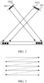
- FIG. 2 is a diagram of a structure of scanning an image by the projection apparatus.
- the projection apparatus 100 provided in this application controls the MEMS lens 1032 that rotates around the cantilever beam 1031, to enable the MEMS lens 1032 to rotate at a specific angle, in other words, move along a specific track, and scan the pixel array 102.
- the pixel array 102 is disposed at a front end of the MEMS lens 1032 and between the MEMS lens 1032 and a projection imaging position.
- the pixel array 102 may be attached to the MEMS lens 1032, as shown in FIG.
- FIG. 2 may be fastened between the MEMS lens 1032 and the projection imaging position, provided that color display of the pixel array 102 can be performed to enable imaging to be performed at the projection imaging position with different angles at which the MEMS lens 1032 rotates.
- a specific position shown in FIG. 2 is not used as a limitation.
- a moving track of the MEMS lens 1032 may be determined based on an image that needs to be imaged or the pixel array 102.
- the moving track may be determined based on that a complete image that needs to be imaged can be obtained or that the pixel array 102 can be completely covered.
- FIG. 3 is a diagram of the moving track of the MEMS lens.
- the MEMS lens 1032 rotates at the angle shown in FIG. 2 and performs scanning, to be specific, rotates from a scanning position of the MEMS lens 1032 identified by a solid line in FIG. 2 to another scanning position of the MEMS lens 1032 identified by a dashed line, and then rotates from the position of the MEMS lens 1032 identified by the dashed line to the scanning position of the MEMS lens 1032 identified by the solid line, to repeatedly perform rotation and scanning, a scanning track formed is the moving track shown in FIG. 3 .
- the MEMS lens 1032 repeatedly scans the pixel array 102 along the moving track, and projects different image blocks at different projection positions. The image blocks may be combined to obtain a frame of a complete projected image.
- the projected image needs to be displayed.
- the MEMS lens 1032 repeatedly scans, along a fixed scanning track, the pixel array 102 covered by the scanning track.
- FIG. 3 is merely used as an example, and the moving track of the MEMS lens 1032 is not limited to the scanning track.
- the MEMS lens scanner 103 may be classified into a one-dimensional lens scanner and a two-dimensional lens scanner.
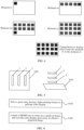
- FIG. 4 is a diagram of scanning display of a projection apparatus according to an embodiment of this application. As shown in FIG. 4 , the projection apparatus 100 obtains different image blocks at a group of sampling time points. Each image block corresponds to a part of a complete projected image. The image blocks may be combined to present a frame of the complete projected image.
- a MEMS lens scanner 103 is a one-dimensional lens scanner.
- a driver 104 is specifically configured to control a MEMS lens 1032 to rotate along a cantilever beam 1031 within a first angle and scan a color-display pixel array 102, to obtain first image blocks obtained through scanning by the MEMS lens 1032 at a group of sampling time points. The first image blocks at the group of sampling points form the projected image.
- the MEMS lens scanner 103 is a one-dimensional lens scanner, and the one-dimensional lens scanner may perform rapid transverse scanning.
- the first angle may be 50 degrees.
- the driver 104 controls the MEMS lens 1032 to rotate along the cantilever beam 1031 within ⁇ 50 degrees.
- a plurality of first image blocks may be respectively obtained at groups of sampling time points from t1 to tn and from tm to ts.
- a complete frame including all the first image blocks corresponding to the group of sampling time points is a frame of projected image that needs to be projected.
- the first angle herein may alternatively be set to 90 degrees, 30 degrees, or the like. This is not limited in the foregoing example.
- a MEMS lens scanner 103 is a two-dimensional lens scanner, and the two-dimensional lens scanner may perform scanning in two directions. Based on different scanning modes, two axes may be generally classified into a fast axis and a slow axis. For example, it may be determined that the fast axis controls a MEMS lens 1032 in one dimension to rotate along a cantilever beam 1031, and the slow axis controls a MEMS lens 1032 in the other dimension to rotate in a direction perpendicular to the cantilever beam 1031.
- a driver 104 is specifically configured to: control the MEMS lens 1032 in one dimension to rotate along the cantilever beam 1031 within a second angle and scan a color-display pixel array, to obtain second image blocks obtained through scanning by the MEMS lens 1032 at a group of sampling time points; and control the MEMS lens 1032 in the other dimension to rotate in the direction perpendicular to the cantilever beam 1031 within a third angle and scan the color-display pixel array 102, to obtain third image blocks obtained through scanning by the MEMS lens 1032 at another group of sampling time points.
- the second image blocks and the third image blocks form the projected image.
- the driver 104 controls the MEMS lens 1032 in one dimension to rotate along the cantilever beam 1031 within ⁇ 50 degrees and scan the color-display pixel array, to obtain the second image blocks, for example, image blocks in a first row in FIG. 4 , obtained through scanning by the MEMS lens 1032 at the group of sampling time points from t1 to tn shown in FIG. 4 .
- the driver 104 controls the MEMS lens 1032 in the other dimension to rotate in the direction perpendicular to the cantilever beam 1031 within ⁇ 10 degrees and scan the color-display pixel array, to obtain the third image blocks obtained through scanning by the MEMS lens 1032 at the group of sampling time points from tm to ts shown in FIG. 4 .
- a frame of a complete projected image that needs to be projected may be formed.
- Time for forming a frame of a complete projected image is less than time for human eyes to distinguish image frame switching. Therefore, a user can normally use the projection apparatus to project and view a picture or a video, and user experience is not affected by combining the plurality of image blocks to obtain the projected image.
- the second angle and the third angle in this example may alternatively be determined based on an actual scanning requirement, and are not limited to the foregoing example.
- the projected image obtained based on the foregoing manner may provide a plurality of pieces of resolution based on an actual requirement.
- a requirement for resolution of the projected image is high, the projected image can achieve high resolution.
- Both the one-dimensional MEMS lens and the two-dimensional MEMS lens have an adaptive application scenario.
- the projection apparatus needs to be in a small size for adaptation.
- the projection apparatus may be configured with only the one-dimensional MEMS lens.
- the projection apparatus needs to provide a 480*640 projected image, and the pixel array is a 1*480 array
- longitudinal resolution may be provided by color display of a longitudinal pixel array during each time of scanning, and horizontal resolution needs to be obtained by requiring the one-dimensional MEMS lens scanner to scan 640 real pixels to support obtaining the projected image.
- this scanning manner requires to scan and sample more image blocks horizontally, a configuration of the projection apparatus is simpler, the resolution can also meet the requirement, and the scanning manner is applicable to a scenario with a low configuration requirement.
- a requirement for the resolution of the projected image and an arrangement manner of subpixels of the pixel array may be adjusted based on an actual requirement, and are not limited in this example.
- the two-dimensional MEMS lens scanner scans a same image to obtain projected images with same resolution.
- the scanning may be performed in two directions at the same time.
- a configuration is slightly more complex than that of the one-dimensional MEMS lens scanner, the projected image can be obtained faster, and the two-dimensional MEMS lens scanner is applicable to a scenario with a higher requirement for an imaging speed.
- the driver 104 is specifically configured to: in a same timing, control the MEMS lens scanner 103 to perform scanning, and drive the pixel array 102 to perform color display.
- the driver 104 respectively outputs the two parts of drive signals.
- a logic control signal is used to control the MEMS lens 1032 of the MEMS lens scanner 103
- an electrical signal is used to drive the pixel array 102 to perform color display.
- the two parts of drive signals need to ensure that, in the same timing, the MEMS lens scanner 103 is controlled and the pixel array 102 is driven. Ensuring real-time performance can ensure that color display of the pixel array 102 is consistent with scanning driving of the MEMS lens scanner 103, so that the projected image is displayed more accurately and a display effect is better.
- the pixel array 102 includes a plurality of pixel blocks 1021.
- FIG. 5 is a diagram of arrangement and distribution in the pixel block.
- the pixel block 1021 includes: red, green, and blue subpixels that are disposed in parallel on a horizontal plane and that have a light-emitting feature, or red, green, and blue subpixels that are disposed in a stacked manner in a vertical direction and that have a light-emitting feature.
- the red, green, and blue subpixels in the pixel block 1021 are respectively denoted as a red subpixel 1, a green subpixel 2, and a blue subpixel 3, and the three subpixels may be arranged in different forms.
- one pixel block may include three subpixels: red, green, and blue subpixels that are disposed in parallel on a horizontal plane.
- one pixel block includes three subpixels: red, green, and blue subpixels that are disposed in a stacked manner in a vertical direction.
- the three subpixels disposed in parallel on the horizontal plane may be disposed horizontally like subpixels disposed horizontally on a liquid crystal display screen.
- the three subpixels that are disposed in the stacked manner in the vertical direction are vertically arranged in a depth direction. From a perspective of a top view direction, the three subpixels overlap each other.
- a sequence of red, green, and blue may be adjusted as required, and is not limited to a sequence marked in the figure.
- red, green, and blue subpixels are arranged based on a general pixel arrangement distance of the liquid crystal display screen.
- the pixel array 102 is a micro LED array or a micro OLED array.
- a micro LED technology is an LED miniaturization and matrix technology, and means that in a high-density and small-sized LED array integrated on a chip, each subpixel can be independently driven.
- a micro OLED technology is an organic light emitting diode miniaturization and matrix technology, and each subpixel may also be independently driven. Therefore, the technologies are applicable to the projection apparatus provided in this application. Independently driven by the driver, each subpixel performs color display based on a drive signal required by a digital processing result, so that each subpixel is scanned to obtain different image blocks of an image that needs to be projected, to further form a frame of a complete projected image.
- the projection apparatus further includes an optical structure disposed on a surface of the pixel array 102.
- the optical structure is configured to calibrate emitted light of the pixel array to emitted light featured by a narrow beam and high collimation.
- the optical structure may be a DBR structure, a micro lens structure, or the like. These optical structures may reduce a light emitting angle of the micro LED pixel array or the micro OLED pixel array as much as possible, so that a beam emitted by the micro LED pixel array or the micro OLED pixel array is featured by a narrow beam and high collimation.
- a scanning track of the MEMS lens is that a start end of the scanning track does not extend an utmost edge of the pixel array scanned by the MEMS lens.
- the scanning track of the MEMS lens may be in a plurality of forms such as up to down and left to right, provided that a plurality of image blocks can be obtained through scanning on the track of the MEMS lens to form a frame of a complete projected image.
- the scanning track greatly extends the subpixel, a drive waste is caused, and imaging time is prolonged. Therefore, the scanning track may be set to a shortest track on a scanning path that can ensure imaging.
- a scanning start end does not extend a subpixel at the utmost edge of the pixel array.
- a termination end of the scanning track does not extend the subpixel at the utmost edge of the pixel array scanned by the MEMS lens.
- the pixel array in the projection apparatus provided in this embodiment of this application may be prepared on the MEMS lens.
- the micro LED array or the micro OLED array may be prepared on the MEMS lens based on the foregoing example.
- the MEMS lens scanner may be a one-dimensional lens scanner, namely, a lens scanner having a cantilever beam structure in one direction.
- the MEMS lens scanner may be a two-dimensional lens scanner, namely, a lens scanner having cantilever beam structures in two directions perpendicular to each other.
- the micro LED array or the micro OLED array has M*N pixel blocks, where M ⁇ 1, N ⁇ 1, and M*N> 1.
- the pixel blocks are arranged and distributed with reference to the pixel arrangement distance in the liquid crystal display screen.
- RGB color subpixels of each pixel block may be arranged in different manners.
- the RGB subpixels are separated on a plane, or the RGB subpixels are located in a same plane position, and are arranged in the stacked manner in sequence in the vertical direction.
- An arrangement manner of the subpixels is not limited in embodiments of this application.
- the MEMS lens During actual display, the MEMS lens repeatedly performs scanning along a fixed scanning track.
- the micro LED or the micro OLED integrated on a MEMS lens scanner performs corresponding color display in real time.
- a scanning process of the MEMS lens a plurality of image blocks are obtained one by one by properly driving the micro LED pixel array or the micro OLED pixel array.
- the image blocks are combined to finally form a two-dimensional display picture, namely, the projected image.
- an optical structure may be prepared on a surface of the micro LED pixel array or the micro OLED pixel array, to reduce the light emitting angle of the micro LED or the micro OLED as much as possible, so that the beam emitted by the micro LED or the micro OLED is featured by a narrow beam and high collimation.
- FIG. 4 When the MEMS lens performs scanning along a fixed two-dimensional scanning track, a finally formed effect is shown in FIG. 4 .
- the MEMS lens is at an angle, and the micro LED pixel array or the micro OLED pixel array is displayed in an upper left corner of a finally displayed picture.
- the micro LED pixel array or the micro OLED pixel array displays a picture at different positions of a to-be-displayed projected image, that is, display an image block. For example, at the moment tn, an image block is displayed at another position based on the previous image block.
- the micro LED pixel array or the micro OLED pixel array displays a picture at different vertical positions of the to-be-displayed projected image, as shown in the moment tm and the moment ts.
- an entire two-dimensional display picture may be formed, and a frame of projected image is correspondingly displayed. This process is repeated, and a plurality of frames of projected images may form a projected video or the like.
- the two-dimensional display picture that can be formed finally is the projected image.
- the displayed two-dimensional picture may be analyzed, and an image processing method is optimized to obtain a more appropriate drive signal, to improve a display effect.
- the step may be performed during debugging of the projection apparatus. Alternatively, optimization and debugging may be performed by a built-in processor during use. This is not limited herein.
- the pixel array having a light-emitting feature and the MEMS lens scanner that scans the array are driven to obtain the projected image.
- a high-resolution projected image can be obtained without a need of a large-sized optical module for providing a light source and without requiring the MEMS to be driven at a high speed.
- An image above a 1080P level can be projected under a condition that a projection apparatus is ensured to be smaller than 2 cubic centimeters. This resolves a problem in the conventional technology that high resolution requires a large-sized projection device, and a small-sized projection device projects a low-resolution projected image.
- FIG. 6 is a flowchart of the projection method according to this embodiment of this application. The method includes the following steps.
- S101 Drive a pixel array having a light-emitting feature to perform color display.
- the pixel array may be a rectangular pixel array including a plurality of pixel blocks, for example, including M pixel blocks in each row and N pixel blocks in each column.
- the pixel block includes three subpixels: red, green, and blue subpixels.
- the subpixels have a light-emitting feature. M ⁇ 1, N ⁇ 1, and M*N> 1.
- S102 Control a MEMS lens to rotate on a cantilever beam and scan the color-display pixel array, to obtain a projected image.
- the cantilever beam is disposed outside the pixel array and is configured to fasten the MEMS lens.
- the MEMS lens is configured to scan the pixel array.
- the cantilever beam and the MEMS lens form a MEMS lens scanner.
- the MEMS lens scanner is a one-dimensional lens scanner.
- Controlling the MEMS lens to rotate on the cantilever beam and scan the color-display pixel array, to obtain the projected image includes: controlling the one-dimensional MEMS lens to rotate along the cantilever beam within a first angle and scan the color-display pixel array, to obtain first image blocks obtained through scanning by the MEMS lens at a group of sampling time points, where the first image blocks at the group of sampling points form the projected image.
- the MEMS lens scanner is a two-dimensional lens scanner.
- Controlling the MEMS lens to rotate on the cantilever beam and scan the color-display pixel array, to obtain the projected image includes: controlling a MEMS lens scanner in one dimension to rotate along the cantilever beam within a second angle and scan the color-display pixel array, to obtain second image blocks obtained through scanning by the MEMS lens at a group of sampling time points; and controlling a MEMS lens in the other dimension to rotate in a direction perpendicular to the cantilever beam within a third angle and scan the color-display pixel array, to obtain third image blocks obtained through scanning by the MEMS lens at another group of sampling time points, where the second image blocks and the third image blocks form the projected image.
- driving the pixel array having a light-emitting feature to perform color display; and controlling the MEMS lens to rotate on the cantilever beam and scan the color-display pixel array, to obtain the projected image may be: in a same timing, driving the pixel array having a light-emitting feature to perform color display, and controlling the MEMS lens to rotate on the cantilever beam and scan the color-display pixel array, to obtain the projected image.
- information about a to-be-projected image may be output as two parts of drive signals.
- One signal is used to drive the MEMS lens to rotate and scan the color-display pixel array, to obtain the projected image
- the other signal is used to drive the pixel array to perform color display, for example, drive a micro LED array or a micro OLED array to perform color display.
- the two driving processes need to be performed in a same timing to ensure a display effect of the projected image.
- a scanning track of the MEMS lens is that a start end of the scanning track does not extend an utmost edge of the pixel array scanned by the MEMS lens.
- the scanning track of the MEMS lens is that a termination end of the scanning track does not extend the utmost edge of the pixel array scanned by the MEMS lens.
- the method is applicable to image projection in the projection apparatus by using the method in the foregoing example of the projection apparatus, but is not limited to being applicable to the foregoing projection apparatus.
- the pixel array having a light-emitting feature and the MEMS lens scanner that scans the array are driven to obtain the projected image.
- a high-resolution projected image can be obtained without a need of a large-sized optical module for providing a light source and without requiring the MEMS to be driven at a high speed. This enables a small-sized projection apparatus to provide a higher-resolution projected image, and achieves an objective of optimizing a size and increasing resolution.
- the computer-readable medium includes a computer storage medium and a communication medium.
- the communication medium includes any medium that facilitates transmission of a computer program from one place to another.
- the storage medium may be any available medium accessible to a general-purpose or dedicated computer.
Landscapes
- Physics & Mathematics (AREA)
- General Physics & Mathematics (AREA)
- Engineering & Computer Science (AREA)
- Multimedia (AREA)
- Signal Processing (AREA)
- Optics & Photonics (AREA)
- Mechanical Optical Scanning Systems (AREA)
- Mechanical Light Control Or Optical Switches (AREA)
Applications Claiming Priority (2)
| Application Number | Priority Date | Filing Date | Title |
|---|---|---|---|
| CN202210157804.7A CN116661223B (zh) | 2022-02-21 | 2022-02-21 | 投影装置及方法 |
| PCT/CN2022/124862 WO2023155450A1 (fr) | 2022-02-21 | 2022-10-12 | Dispositif et procédé de projection |
Publications (3)
| Publication Number | Publication Date |
|---|---|
| EP4474902A1 true EP4474902A1 (fr) | 2024-12-11 |
| EP4474902A4 EP4474902A4 (fr) | 2025-05-21 |
| EP4474902B1 EP4474902B1 (fr) | 2026-08-19 |
Family
ID=87577438
Family Applications (1)
| Application Number | Title | Priority Date | Filing Date |
|---|---|---|---|
| EP22926755.4A Active EP4474902B1 (fr) | 2022-02-21 | 2022-10-12 | Dispositif et procédé de projection |
Country Status (4)
| Country | Link |
|---|---|
| US (1) | US20250039341A1 (fr) |
| EP (1) | EP4474902B1 (fr) |
| CN (1) | CN116661223B (fr) |
| WO (1) | WO2023155450A1 (fr) |
Cited By (1)
| Publication number | Priority date | Publication date | Assignee | Title |
|---|---|---|---|---|
| CN121276872A (zh) * | 2025-11-25 | 2026-01-06 | 深圳市橙子数字科技有限公司 | 基于Mini LED阵列与可变微结构光导的投影系统及方法 |
Family Cites Families (17)
| Publication number | Priority date | Publication date | Assignee | Title |
|---|---|---|---|---|
| US5903380A (en) * | 1997-05-01 | 1999-05-11 | Rockwell International Corp. | Micro-electromechanical (MEM) optical resonator and method |
| US6288815B1 (en) * | 1999-03-31 | 2001-09-11 | Philips Electronics North America Corporation | Light scanner with cylindrical lenses |
| US6433907B1 (en) * | 1999-08-05 | 2002-08-13 | Microvision, Inc. | Scanned display with plurality of scanning assemblies |
| CN1710459A (zh) * | 2005-07-15 | 2005-12-21 | 李凌 | 一种微机电系统(mems)二维振镜及其制作方法 |
| US20070091037A1 (en) * | 2005-10-21 | 2007-04-26 | Yee-Chun Lee | Energy Efficient Compact Display For Mobile Device |
| JP5190860B2 (ja) * | 2007-01-22 | 2013-04-24 | 学校法人東京電機大学 | 投影露光装置および投影露光方法 |
| CN101295123B (zh) * | 2007-04-25 | 2012-07-25 | 中国科学院光电研究院 | 一种基于闪耀光栅光调制器的显示系统 |
| EP4012480A1 (fr) * | 2016-08-08 | 2022-06-15 | Essilor International | Dispositif monté sur la tête comprenant un projecteur conçu pour projeter une image |
| CN106125479A (zh) * | 2016-08-08 | 2016-11-16 | 常州创微电子机械科技有限公司 | 多激光扫描投影系统 |
| US11314083B2 (en) * | 2018-02-06 | 2022-04-26 | Google Llc | Beam steering optics for near-eye and head mounted displays |
| CN108398779B (zh) * | 2018-02-12 | 2020-05-15 | 西安知微传感技术有限公司 | 一种基于振镜的螺旋线扫描激光投影方法及系统 |
| US20200285055A1 (en) * | 2019-03-08 | 2020-09-10 | Varjo Technologies Oy | Direct retina projection apparatus and method |
| US11513431B2 (en) * | 2019-01-25 | 2022-11-29 | Cepton Technologies, Inc. | Systems and methods for light projection |
| CN112015035B (zh) * | 2019-05-30 | 2022-05-20 | 成都理想境界科技有限公司 | 一种偏振光源、扫描投影装置及设备 |
| CN110347008A (zh) * | 2019-06-03 | 2019-10-18 | 歌尔股份有限公司 | 一种投影装置 |
| TWI712180B (zh) * | 2019-10-22 | 2020-12-01 | 錼創顯示科技股份有限公司 | 微型發光二極體晶粒及微型發光二極體晶圓 |
| KR102789414B1 (ko) * | 2019-12-27 | 2025-04-03 | 삼성전자주식회사 | 프로젝터 |
-
2022
- 2022-02-21 CN CN202210157804.7A patent/CN116661223B/zh active Active
- 2022-10-12 EP EP22926755.4A patent/EP4474902B1/fr active Active
- 2022-10-12 WO PCT/CN2022/124862 patent/WO2023155450A1/fr not_active Ceased
-
2024
- 2024-08-20 US US18/809,861 patent/US20250039341A1/en active Pending
Cited By (1)
| Publication number | Priority date | Publication date | Assignee | Title |
|---|---|---|---|---|
| CN121276872A (zh) * | 2025-11-25 | 2026-01-06 | 深圳市橙子数字科技有限公司 | 基于Mini LED阵列与可变微结构光导的投影系统及方法 |
Also Published As
| Publication number | Publication date |
|---|---|
| EP4474902A4 (fr) | 2025-05-21 |
| CN116661223B (zh) | 2026-06-05 |
| US20250039341A1 (en) | 2025-01-30 |
| CN116661223A (zh) | 2023-08-29 |
| WO2023155450A1 (fr) | 2023-08-24 |
| EP4474902B1 (fr) | 2026-08-19 |
Similar Documents
| Publication | Publication Date | Title |
|---|---|---|
| US10051209B2 (en) | Combined visible and non-visible projection system | |
| US11137498B2 (en) | Scanning rangefinding system with variable field of view | |
| US7123213B2 (en) | Three dimensional display unit and display method | |
| US8556431B2 (en) | Apparatus and method for reducing speckle in display of images | |
| EP2278798A2 (fr) | Lecteur multimédia affichant deux images de projection | |
| US7111943B2 (en) | Wide field display using a scanned linear light modulator array | |
| US5993003A (en) | Autostereo projection system | |
| US20090195709A1 (en) | Image projection system and method | |
| EP3345050B1 (fr) | Constance dynamique de la luminosité ou de la taille d'un contenu projeté dans un système d'affichage à balayage | |
| US12189127B2 (en) | Projection device and projection method for head mounted display based on rotary MEMS fast scanner | |
| JP2003172900A (ja) | 画像投影表示装置、画像投影表示システム並びに画像投影表示方法 | |
| JP2005292657A (ja) | 投写型表示装置および投写型表示システム | |
| JP2003186112A (ja) | 画像投影表示装置 | |
| CN106125479A (zh) | 多激光扫描投影系统 | |
| CN103048869A (zh) | 高视角分辨率的360°视场三维显示装置和显示方法 | |
| US20250039341A1 (en) | Projection Apparatus and Method | |
| US9160992B2 (en) | Projection apparatus having MEMS mirror with plural projection paths | |
| US20080309832A1 (en) | Projection display apparatus and display method applied to the same | |
| WO2024088090A1 (fr) | Dispositif de projection et procédé d'affichage d'image de projection afférent | |
| KR20100078688A (ko) | 프로젝션 디스플레이 장치 및 그를 이용한 디스플레이 방법 | |
| JP3228767B2 (ja) | 液晶パネル及び液晶表示装置 | |
| US12451036B2 (en) | Laser projection apparatus, projection display system, and projection display method | |
| JP2014119687A (ja) | スクリーン装置および表示装置 | |
| US11908353B2 (en) | Information processing apparatus and information processing system | |
| KR20190052418A (ko) | 프로젝터 및 그의 동작 방법 |
Legal Events
| Date | Code | Title | Description |
|---|---|---|---|
| STAA | Information on the status of an ep patent application or granted ep patent |
Free format text: STATUS: THE INTERNATIONAL PUBLICATION HAS BEEN MADE |
|
| PUAI | Public reference made under article 153(3) epc to a published international application that has entered the european phase |
Free format text: ORIGINAL CODE: 0009012 |
|
| STAA | Information on the status of an ep patent application or granted ep patent |
Free format text: STATUS: REQUEST FOR EXAMINATION WAS MADE |
|
| 17P | Request for examination filed |
Effective date: 20240903 |
|
| AK | Designated contracting states |
Kind code of ref document: A1 Designated state(s): AL AT BE BG CH CY CZ DE DK EE ES FI FR GB GR HR HU IE IS IT LI LT LU LV MC ME MK MT NL NO PL PT RO RS SE SI SK SM TR |
|
| A4 | Supplementary search report drawn up and despatched |
Effective date: 20250425 |
|
| RIC1 | Information provided on ipc code assigned before grant |
Ipc: G02B 26/10 20060101ALN20250417BHEP Ipc: G02B 26/08 20060101ALI20250417BHEP Ipc: G03B 21/00 20060101AFI20250417BHEP |
|
| DAV | Request for validation of the european patent (deleted) | ||
| DAX | Request for extension of the european patent (deleted) | ||
| GRAP | Despatch of communication of intention to grant a patent |
Free format text: ORIGINAL CODE: EPIDOSNIGR1 |
|
| STAA | Information on the status of an ep patent application or granted ep patent |
Free format text: STATUS: GRANT OF PATENT IS INTENDED |
|
| RIC1 | Information provided on ipc code assigned before grant |
Ipc: G03B 21/00 20060101AFI20260226BHEP Ipc: G02B 26/08 20060101ALI20260226BHEP Ipc: G02B 26/10 20060101ALN20260226BHEP |
|
| INTG | Intention to grant announced |
Effective date: 20260317 |
|
| GRAS | Grant fee paid |
Free format text: ORIGINAL CODE: EPIDOSNIGR3 |
|
| GRAA | (expected) grant |
Free format text: ORIGINAL CODE: 0009210 |
|
| STAA | Information on the status of an ep patent application or granted ep patent |
Free format text: STATUS: THE PATENT HAS BEEN GRANTED |