EP4474784A1 - Verwendung eines geräts zur messung der lufttemperatur - Google Patents
Verwendung eines geräts zur messung der lufttemperatur Download PDFInfo
- Publication number
- EP4474784A1 EP4474784A1 EP24179696.0A EP24179696A EP4474784A1 EP 4474784 A1 EP4474784 A1 EP 4474784A1 EP 24179696 A EP24179696 A EP 24179696A EP 4474784 A1 EP4474784 A1 EP 4474784A1
- Authority
- EP
- European Patent Office
- Prior art keywords
- optical fiber
- temperature
- use according
- measuring
- length
- Prior art date
- Legal status (The legal status is an assumption and is not a legal conclusion. Google has not performed a legal analysis and makes no representation as to the accuracy of the status listed.)
- Granted
Links
Images




Classifications
-
- G—PHYSICS
- G01—MEASURING; TESTING
- G01K—MEASURING TEMPERATURE; MEASURING QUANTITY OF HEAT; THERMALLY-SENSITIVE ELEMENTS NOT OTHERWISE PROVIDED FOR
- G01K11/00—Measuring temperature based upon physical or chemical changes not covered by groups G01K3/00, G01K5/00, G01K7/00 or G01K9/00
- G01K11/32—Measuring temperature based upon physical or chemical changes not covered by groups G01K3/00, G01K5/00, G01K7/00 or G01K9/00 using changes in transmittance, scattering or luminescence in optical fibres
- G01K11/324—Measuring temperature based upon physical or chemical changes not covered by groups G01K3/00, G01K5/00, G01K7/00 or G01K9/00 using changes in transmittance, scattering or luminescence in optical fibres using Raman scattering
-
- G—PHYSICS
- G01—MEASURING; TESTING
- G01K—MEASURING TEMPERATURE; MEASURING QUANTITY OF HEAT; THERMALLY-SENSITIVE ELEMENTS NOT OTHERWISE PROVIDED FOR
- G01K13/00—Thermometers specially adapted for specific purposes
- G01K13/02—Thermometers specially adapted for specific purposes for measuring temperature of moving fluids or granular materials capable of flow
- G01K13/024—Thermometers specially adapted for specific purposes for measuring temperature of moving fluids or granular materials capable of flow of moving gases
-
- G—PHYSICS
- G01—MEASURING; TESTING
- G01K—MEASURING TEMPERATURE; MEASURING QUANTITY OF HEAT; THERMALLY-SENSITIVE ELEMENTS NOT OTHERWISE PROVIDED FOR
- G01K2213/00—Temperature mapping
Definitions
- the invention relates to a device for measuring air temperature and its use.
- the field of the invention relates to measurements of the air temperature in rooms, such as for example in nuclear power plants for producing electricity.
- Radiative effects correspond to the consequences in terms of heat exchanges on a body, of the electromagnetic radiation emitted by another body (radiant).
- This mode of heat transfer occurs without transport of matter depending on the temperature of the radiating body. The higher the temperature of the radiating body, the more intense the thermal radiation is at short wavelengths.
- An example illustrating this mode of transfer concerns the thermal radiation emitted by the sun, which is located mainly in the visible.
- Air is a medium that is almost transparent to thermal radiation.
- any air temperature measuring instrument evaluates the air temperature from its own temperature and, as a solid body, exchanges thermal radiation with its environment, which generally results in measurement biases that can be of the first order.
- measurement biases that can be of the first order.
- Air temperature measurements are generally intended to ensure that equipment associated with these environments or temperature measurement areas are or will be in suitable conditions for the intended activities.
- the different fields in which such measurements are carried out are relatively diverse and can be in the field of meteorology where we generally seek to measure the atmospheric temperature, in the biological and medical field where we wish to finely control the temperature and quality of the air to avoid for example the development of bacteria, fungi or mites, in the field of physical measurement where we wish to have controlled measurements to participate in the characterization of physical phenomena.
- the field of the invention concerns instruments and methods for measuring air temperature in an environment presenting or capable of presenting significant exchanges by radiation.
- This concerns both industrial premises with equipment having hot surfaces and outdoor environments where there is significant sunlight.
- the professions concerned are those seeking to have metrologically controlled air temperature measurements, i.e. with confidence and a guarantee regarding the measurements resulting from the air temperature measurement processes.
- the material of the sensitive probe is influenced by the heat input provided by the radiation, which induces an error in the measurement of the air temperature.
- An objective of the invention is to obtain a use of a temperature measuring device, which solves the above-mentioned problem related to measurement biases and which makes it possible to reliably and locally measure the air temperature in the possible presence of radiating external elements.
- a first object of the invention is a use of a measuring device comprising at least one optical fiber coated with an external coating, which is made of a material having an emissivity less than or equal to 0.1, which is bare, which is exposed to the air over at least a major part of a length of the optical fiber and which has an external diameter less than or equal to 200 ⁇ m, for measuring the air temperature at at least one measuring point located on an external surface of the external coating.
- the optical fiber has a small external diameter, in order to promote convective effects, and has a low-emissivity coating over a large part of the spectrum (in particular in the visible and infrared), which limits radiative heat exchanges and ultimately makes the biases of radiative effects negligible.
- convective effects correspond to the consequences in terms of heat exchanges at the interface between a fluid and a solid or a liquid, generated by the internal movements animating the fluid.
- the invention avoids having to have as many probes as sampled measurement points, which are restrictive in terms of implementation.
- the invention avoids in particular the following difficulties: as many measurement channels as sensors, as many calibrations as sensors, wired connections of the equipment, high costs, effects of disturbance of the air flow, low fineness of the mesh.
- the material of the external coating is metallic.
- the material of the external covering is aluminum.
- the material of the external coating is gold.
- the measuring device comprises a module for sampling several temperature measurements at several measuring points along the length of the optical fiber.
- the measuring device comprises at least one pair of supports spaced apart from each other, the at least one optical fiber coated with the outer coating is attached to the supports and extends between the supports for the majority of the length of the optical fiber, the outer coating of which is bare and exposed to air.
- the supports comprise posts.
- several sections of the length of the optical fiber coated with the external coating each extend in a first measurement direction between the supports of the at least one pair of supports and are spaced from each other at least in a second direction perpendicular to the first measurement direction.
- the sections of the length of the optical fiber coated with the external coating are located in a measurement plane comprising the first measurement direction and the second direction.
- a two-dimensional temperature map is calculated by a calculator of the measuring device, by interpolation of the temperature measurements taken respectively at the measuring points along the length of the optical fiber, in order to calculate the temperature at interpolation points of the measuring plane, which are located between the sections of the optical fiber of the at least one pair of supports and/or which are located between the measuring points along the length of the optical fiber.
- the measuring device comprises several optical fibers coated with the external coating and respectively several pairs of the supports, spaced along a third direction, which is perpendicular to the first measurement direction and to the second direction, the optical fibers coated with the outer coating being respectively fixed to the supports of the pairs and extending respectively between the supports of the pairs over the major part of the length of the optical fibers, the outer coating of which is bare and exposed to the air.
- a three-dimensional temperature map is calculated by a calculator of the measuring device, by interpolation of the temperature measurements taken respectively at the measuring points along the length of the optical fiber, in order to calculate the temperature at interpolation points in space, which are located between the sections of the optical fiber spaced apart along the third direction and/or which are located between the sections of the optical fiber along the second direction and/or which are located between the measuring points along the length of the optical fiber.
- the measuring device comprises a screen for displaying the mapping.
- the second direction is vertical
- the sections of the length of the optical fiber have between them a spacing in the second direction, which is smaller at the top than at the bottom.
- At least a first of the optical fibers and at least a second of the optical fibers are arranged at a distance from an object and on either side of the object in the third direction, for measuring the temperature on either side of the object in the third direction.
- the measuring device comprises a calculation module, which is connected to at least one end of the optical fiber and which is configured to calculate the air temperature at at least one measurement point located on the external surface of the external coating, by reflectometry of first signals emitted in the optical fiber, to calculate the at least one measurement of the temperature at at least one measurement point on the external surface of the optical fiber.
- the calculation module comprises at least one Raman type interrogator.
- the Raman type interrogator comprises at least one transmitter for transmitting first signals along the optical fiber, at least one receiver for receiving second signals, which are reflected by the optical fiber in response to the first signals, and a calculator configured to calculate the temperature from a ratio ( P s t l P as t l ) of power of two lines of different prescribed frequencies, which correspond to a Stokes peak and an anti-Stokes peak and which are present in the second signals.
- P s the Stokes peak power measured by the receiver
- P as the anti-Stockes peak power measured by the receiver
- t time
- l the abscissa of the measurement point along the first direction along the optical fiber from the Raman interrogator
- T offset is a prescribed coefficient of the Raman interrogator
- ⁇ ⁇ is a prescribed coefficient of differential attenuation between the Stockes peak and the anti-Stockes peak
- ⁇ and C ( t ) are intrinsic parameters of the Raman interrogator.
- a calculator of the measuring device performs a spatial recalibration of the measurements of the air temperature along the length of the optical fiber, by identifying by the calculator the temperature measured at at least one prescribed position along the length of the at least one optical fiber, on which a source of prescribed temperature gradient is imposed on the external coating.
- the prescribed position of the temperature gradient source is located on at least one of the supports.
- the prescribed temperature gradient source is arranged on the outer coating at several prescribed positions located respectively on several sections of the length of the optical fiber coated with the outer coating, spaced from each other at least in the second direction.
- the prescribed temperature gradient source comprises a heating cable.
- the same heating cable passes over the prescribed positions located on the same support.
- the calculator performs spatial oversampling of temperature maxima located at prescribed positions located on the same support, in order to perform spatial recalibration of the air temperature measurements along the length of the optical fiber.
- the prescribed temperature gradient source comprises a cold air projection source.
- the measuring device 1 comprises an optical fiber 3 coated with an external coating 4.
- the optical fiber 3 may comprise a core 3a having a certain index for the propagation of signals in and along the optical fiber 3, which extends in a first measurement direction X.
- the signals are in a certain spectrum, visible or infrared, for example included in the wavelength range from 0.3 ⁇ m to 100 ⁇ m.
- the optical fiber 3 may comprise an optical cladding 3b having an index lower than the index of the core 3a.
- the outer coating 4 is made of a material having an emissivity ⁇ less than or equal to 0.1. In a preferred embodiment, the emissivity ⁇ is less than or equal to 0.05.
- the outer coating 4 has a bare outer surface 40, which is exposed to air over at least a major portion of a length of the optical fiber 3, which extends along a first measurement direction X.
- the outer coating 4 has an outer diameter d, which is less than or equal to 200 ⁇ m.
- the measuring device 1 is configured to measure the air temperature at at least one measuring point x or at several measuring points x, which is (are) located on the external surface 40 of the external coating 4. Of course, several optical fibers 3 each coated with its external coating 4 could be provided in the measuring device 1.
- the optical fiber 3 coated with the external coating 4 forms a sensor of the local air temperature at the measuring point(s) x located on the external surface 40 of the external coating 4.
- the optical fiber 3 coated with the external coating 4 can be straight along the first measuring direction X.
- the first measuring direction X can be horizontal, or other.
- the external coating 4 with low emissivity ⁇ therefore acts as a radiative shield and makes it possible to limit the thermal radiation RTH captured by the material of the fiber 3.
- the small external diameter d of the external coating 4 makes it possible to increase the convection coefficient of the fiber 3 thus coated compared to its radiative coefficient. This therefore favors taking into account the convective effects ECV near the external coating 4.
- the low emissivity ⁇ of the external coating 4 of the optical fiber 3, associated with its external diameter d, makes it possible to reduce the bias in measuring the air temperature on the external surface 40 of the external coating 4 of the optical fiber 3.
- This measurement bias is in fact caused by thermal radiation, which is emitted by surrounding objects or surfaces, towards this external coating 4.
- the invention thus makes it possible to multiply the points x for measuring the air temperature along an optical fiber, without modifying the overall air flows, and makes it possible both to overcome the usual measurement biases generated by radiative effects and to allow, in addition, a spatial meshing of the temperature measurement in one, two or three dimensions and for example of a given volume of air.
- the invention makes it possible to measure by a single sensor 30, formed of the optical fiber 3 and its external coating 4 (in the case where only one aforementioned sensor 30 is provided) the air temperature in several measuring points x.
- several sensors 30 can be provided, as described below with reference to the Figures 4B And 4C .
- the material of the external coating 4 having an emissivity ⁇ less than or equal to 0.1 may be metallic, for example gold or aluminum, or other.
- the surface condition of the external coating 4 may be polished or ultra-polished.
- the emissivity ⁇ of the material of the external coating 4 made of aluminum may be for example of the order of 0.05.
- the emissivity ⁇ of the material of the external coating 4 made of gold may be for example of the order of 0.02.
- the invention allows a measurement of the temperature T of the air subjected to a wide electromagnetic spectrum, visible and infrared, for example from 0.3 ⁇ m to 100 ⁇ m.
- the emissivity ⁇ is considered in this spectrum.
- the optical fiber can be for example made of silica, or other.
- the optical fiber 3 can be single-mode, or preferably multimode.
- the measuring device 1 comprises a module 6 for sampling several measurements of the temperature T at respectively several measurement points x along the length of the optical fiber 3.
- This sampling module 6 can be provided in the calculation module 2 described below or in the Raman type interrogator 20 described below.
- the measuring device 1 comprises a calculation module 2, by reflectometry of first signals emitted in the optical fiber 3, to calculate several measurements of the temperature T at respectively several measurement points x on the external surface 40 of the optical fiber 3, distributed along the first measurement direction X.
- the calculation module 2 is connected to at least one end 32 of the optical fiber 3 and is configured to calculate the temperature T of the air at the measurement points x located on the external surface 40 of the external coating 4.
- the measurements of the temperature T are calculated on the principle of the OTDR (in English: Optical Time-Domain Reflectometer, or optical time-domain reflectometry) from first signals S1, which are emitted by one (or more) transmitters 21 (for example one or more laser sources 21) of the module 2 and which propagate along the optical fiber 3, and from second signals S2, which are reflected by defects in the optical fiber 3 in response to the first signals S1 and which are received by one (or more) receivers 22 (for example one (or more) photodiodes 22) of the module 2.
- the transmitter(s) 21 is (are) connected to the end 32 of the optical fiber 3 via a multiplexer 23 of the module 2.
- the receiver(s) 22 is (are) connected to the end 32 of the optical fiber 3 via the multiplexer 23.
- the transmitter(s) 21 and the receiver(s) 22 are connected to a control unit 24 configured to control these as well as the multiplexer 23.
- This control unit 24 comprises the calculation means or calculators described below.
- the control unit 24 comprises the module 6 for sampling several measurements of the temperature T at respectively several measurement points x along the length of the optical fiber 3.
- the measurement points x can be distributed in a regular manner following a fixed pitch PX along the optical fiber 3 in the first direction X. There is at or near each measurement point x a aforementioned defect in the optical fiber 3, which will reflect the second signals S2.
- the fixed pitch PX is greater than the distance between the aforementioned defects in the optical fiber 3 in the first direction X. There are therefore in each fixed pitch PX several aforementioned defects in the optical fiber 3. May be greater than or equal to 1 cm and less than or equal to 30 cm.
- the fixed pitch PX may for example be of the order of 15 cm.
- the calculation module 2 may be or comprise at least one Raman type interrogator 20 or Raman type spectrometer.
- the Raman effect is a physical phenomenon of inelastic scattering of a photon of the first signals emitted along the optical fiber 3.
- the inelasticity of the scattering of the first signals S1 along the optical fiber 3 causes an exchange of energy between the photon and the fiber 3, which causes a modification of the wavelength of the second reflected signals S2.
- the temperature for different lengths of optical fiber 3 is calculated by the calculator 24 from the power ratio ( P s t l P as t l or vice versa) between two lines S2a, S2b of different prescribed peak frequencies (called Stokes peak S2a and anti-Stokes peak S2b) reflected in the second signals S2 at defects along the optical fiber 3, these defects being unprescribed and random along the optical fiber 3.
- the receiver 22 may comprise a first receiver 22a for detecting and measuring in the second signals S2 the power P s of the Stokes peak S2a, and a second receiver 22b for detecting and measuring in the second signals S2 the power P as of the anti-Stokes peak S2b.
- a modification of the temperature T on the external surface 40 of the external coating 4 modifies this ratio and therefore the measurement of the temperature T, carried out by the module 2.
- the Raman type interrogator 20 emits as first signals S1 a monochromatic laser pulse (for example, for a silica optical fiber 3, at 1064 nm and 1550 nm) and measures by the receivers 22a and 22b the powers P s and P as backscattered within the fiber 3 at the two prescribed frequencies S2a, S2b of the Stokes and anti-Stokes peaks.
- the return time of the pulse in the second reflected signals S2 relative to the emission time of the first emitted signals S1 makes it possible to calculate t.
- T t l T offset + ⁇ ln P s t l P as t l + C t ⁇ l ⁇
- P s is the power of the Stokes peak S2a
- P as is the optical power of the anti-Stockes peak S2b, measured by the photodiodes of the interrogator 20
- T offset is the coefficient of the interrogator 20 to correct for a constant bias
- ⁇ ⁇ is the differential attenuation coefficient ( ⁇ aS ⁇ ⁇ S ) between the Stockes S2a and anti-Stockes S2b peaks
- ⁇ and C ( t ) are prescribed intrinsic parameters of the interrogator 20.
- l ⁇ can be calculated as follows.
- a first measurement is made at the abscissa l by connecting the interrogator 20 to the first end 32 of the optical fiber 3, having the abscissa 0, that is to say in the direct direction, noted ⁇ below, to obtain the optical power P ⁇ Stokes ( l ) of the Stokes peak 32a of this first measurement and the optical power P ⁇ anti - Stokes ( l ) of the anti-Stokes peak S2b of this first measurement.
- a second measurement is carried out at the abscissa l by connecting the interrogator 20 to the second end 33 of the optical fiber 3 (the one far from the first end 32), having the abscissa L, that is to say in the indirect direction, noted ⁇ below, to obtain the optical power P ⁇ Stokes ( l ) of the Stokes peak S2a of this second measurement and the optical power P ⁇ anti-Stokes ( l ) of the anti-Stokes peak S2b of this second measurement.
- T T ( t, l ) of fiber 3
- T l t ⁇ 1 2 ln P ⁇ Stokes l t P ⁇ anti ⁇ Stokes l t + ln P ⁇ Stokes l t P ⁇ anti ⁇ Stokes l t + C t + E t
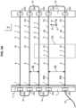
- the measuring device 1 comprises a pair of supports 5 spaced apart from each other, to which the optical fiber 3 coated with the external coating 4 is fixed.
- the optical fiber 3 coated with the external coating 4 extends between the supports 5 in the first measuring direction X over the majority of the length of the optical fiber 3, the external coating 4 of which is bare and exposed to the air between the supports 5.
- Each support 5 may be formed by a post or the like, which may for example be vertical or the like. Several pairs of supports 5 may be provided in the measuring device 1.
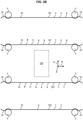
- FIG. 4A , 4B , 4C several sections 31, hereinafter called main sections 31, of the length of the same optical fiber 3 coated with the external coating 4, each extend in the first measurement direction X between the supports 5 of the pair of supports 5 and are spaced from each other at least in the second direction Z perpendicular to the first measurement direction X.
- the first measurement direction X may be horizontal and the second direction Z may be vertical.
- the main sections 31 may be rectilinear in the first measurement direction X.
- the main sections 31 may be connected one after the other by sections secondary curves 34 of the optical fiber 3 coated with the external coating 4.
- the secondary sections 34 are symbolically represented by straight lines but are curved.
- the radius of curvature of the curved secondary sections 34 is greater than the minimum radius of curvature of the optical fiber 3 coated with the external coating 4 (minimum radius of curvature before breaking), and is for example greater than 1.5 times this minimum radius of curvature.
- This minimum radius of curvature can be of the order of 200 times the external diameter d of the external coating 4.
- Means 340 for fixing the secondary sections 34 to the supports 5 are provided. These fixing means can comprise adhesive tapes 340, or any other mechanical fastener.
- Each post 5 can be made of an electrically insulating material, such as for example PVC or other.
- the sections 31 of the length of the optical fiber 3 coated with the external coating 4 are located in a measurement plane P comprising the first measurement direction X and the second direction Z.
- the measurement plane P may be vertical or other. This makes it possible to have a mesh of the temperature measurement in each measurement plane P (for example between the supports 5), without causing an obstruction effect on the air flow.
- the measuring device 1 comprises (for example in the measuring module 2 or in the Raman interrogator 20 or in the control unit 24) a calculator 8 configured to calculate by interpolation the temperature at interpolation points which are located between the measuring points x along the length of the optical fiber 3.
- This interpolation can be for example linear. This makes it possible to improve the spatial meshing of the temperature measurement in one dimension along the optical fiber 3, without generating an obstruction effect on the air flow.
- the measuring device 1 comprises (for example in the measuring module 2 or in the Raman type interrogator 20 or in the control unit 24) a calculator 8 configured to calculate a one-dimensional temperature map 10, by interpolation of the measurements of the temperature T taken respectively at the measurement points x along the length of the optical fiber 3, to calculate the temperature at interpolation points A along the fiber 3 along the measurement direction X, the interpolation points A being located between the measurement points x along the length of the optical fiber 3 along the first measurement direction X.
- This interpolation may be linear, for example.
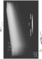
- the measuring device may comprise a screen making it possible to view the one-dimensional temperature map 10, with different gray or color levels depending on the temperature value at each point A and x, as shown as an example in figure 5 .
- the measuring device 1 comprises (for example in the measuring module 2 or in the Raman type interrogator 20 or in the control unit 24) a calculator 8 configured to calculate a two-dimensional temperature map 10, by interpolation of the measurements of the temperature T taken respectively at the measurement points x along the length of the optical fiber 3, to calculate the temperature at interpolation points A of the measurement plane P, the interpolation points A of the measurement plane P being located between the sections 31 of the optical fiber 3 of the pair of supports 5 and/or being located between the measurement points x along the length of the optical fiber 3 along the first measurement direction X.
- This interpolation may be linear, for example.
- the measuring device may comprise a screen for viewing the two-dimensional temperature map 10, with different gray or color levels depending on the temperature value at each point, as shown by way of example in figure 6 .
- the measuring device 1 comprises several optical fibers 3 coated with the external coating 4 and respectively several pairs of the supports 5, to each of which is fixed one of these optical fibers 3 coated with the external coating 4.
- the pairs of the supports 5 are spaced along the third direction Y, which is perpendicular to the first measurement direction X and to the second direction Z.
- the third direction Y can be horizontal or other.
- the optical fibers 3 coated with the external coating 4 are fixed respectively to the pairs of the supports 5 and extend respectively between the supports 5 of the pairs over the major part of the length of the optical fibers 3, the external coating 4 of which is bare and exposed to the air.
- the main section(s) 31 described above may be provided for each optical fiber 3 and each pair of supports 5.
- the secondary section(s) 34 described above may be provided for each optical fiber 3 and each pair of supports 5.
- the main sections 31 of the optical fibers 3 may be located in several other PXY planes containing the first direction X and the third direction Y, these other PXY planes therefore being able to be horizontal. This makes it possible to have spatial meshing of the temperature measurement of a given volume of air in 3 dimensions (for example the volume delimited by the supports 5), without generating an obstruction effect on the air flow.
- the measuring device 1 comprises (for example in the measuring module 2 or in the Raman type interrogator 20 or in the control unit 24) a calculator 8 configured to calculate a three-dimensional temperature map 10, by interpolation of the measurements of the temperature T taken respectively at the measuring points x along the length of the optical fiber 3, to calculate the temperature at interpolation points A in space.
- the interpolation points A are located between the sections 31 of the optical fiber 3 spaced along the third direction Y, that is to say between the measurement planes P (the main sections 31 of the optical fibers 3 neighboring one another may be located in several other planes PXY containing the first direction X and the third direction Y) and/or are located between the sections 31 of the optical fiber 3 along the second direction Z (that is to say in each of the measurement planes P) and/or are located between the measurement points x along the length of the optical fiber 3 along the first measurement direction X.
- This interpolation may be, for example, linear and, for example, three-dimensional of the Delaunay triangulation type.
- the measurement device may include a screen for viewing the three-dimensional temperature map 10, with different gray or color levels depending on the temperature value at each point, as shown by way of example in FIG. figure 7 .
- the sections 31 of the length of the optical fiber 3 have between them a spacing DZ along the second direction Z, which is smaller at the top than at the bottom, the second direction Z being vertical.
- This spacing DZ is located in each measurement plane P.
- the main sections 31 of the optical fibers 3 can be located in several other planes PXY containing the first direction X and the third direction Y, these other planes PXY can therefore be horizontal. This embodiment makes it possible to better measure the stratification of the air. Indeed, there is more heterogeneity in the temperature of the air layers at the top than at the bottom.
- At least a first 301 of the optical fibers 3 and at least a second 302 of the optical fibers 3 are arranged at a distance from an object 200 and on either side of the object 200 in the third direction Y, for measuring the temperature on either side of the object 200 in the third direction Y.
- one, several or all of the sections 31 of the first optical fiber(s) 301 and/or the measurement plane(s) P of the first optical fiber(s) 301 is located in front of the object 200 in the third direction Y.
- One, several or all of the sections 31 of the second optical fiber(s) 302 and/or the measurement plane(s) P of the second optical fiber(s) 3a is located in front of the object 200 in the third direction Y. along the third direction Y. This makes it possible to measure the air temperature at several points in the space around the object 200.
- This object 200 can be of any type, in particular an object giving off heat, for example an electrical cabinet, or other.
- the calculator 8 of the measuring device 1 performs a spatial recalibration of the measurements of the temperature T of the air along the length of the optical fiber 3.
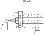
- the measuring device 1 comprises a source 71 of prescribed temperature gradient.
- the source 71 of prescribed temperature gradient is placed against the external surface 40 of the external coating 4 of the optical fiber(s) 3 at one (or more) prescribed position (or point) 7, known, along the length of the optical fiber 3.
- the source 71 of prescribed temperature gradient has a prescribed temperature, known, different from the air temperature.
- the calculator 8 identifies the temperature T measured by the measuring device at the measuring point x located at this prescribed position 7 at the prescribed temperature and known from the prescribed temperature gradient source 71 located at this prescribed position 7.
- the measuring point x having the measured temperature T equal to the prescribed temperature and known from the prescribed temperature gradient source 71 will be reset by the calculator 8 as being located at the prescribed position 7. This makes it possible to reset the three-dimensional coordinates of the measuring points x relative to a reference given by the prescribed position 7.
- the prescribed position 7 of the source 71 of prescribed temperature gradient can be located on one of the supports 5 of the pair, or on several of the supports 5 of the pair.
- the source 71 of prescribed temperature gradient is arranged on the external coating 4 in several prescribed positions 7 located respectively on several sections 31 of the length of the optical fiber 3 coated with the external coating 4, spaced from each other at least in the second direction Z.
- the source 71 of prescribed temperature gradient can therefore pass over several prescribed positions 7 located on the same support 5.
- the source 71 of the prescribed temperature gradient comprises a heating cable 73 (for example electric) having the known prescribed temperature, greater than the air temperature.
- This known prescribed temperature can for example be equal to 50°C.
- the cable heating element 73 can therefore pass over several prescribed positions 7 of the external coating 4 of the optical fiber 3, these prescribed positions 7 being located on the same support 5.
- the prescribed temperature gradient source 71 comprises a source 72 of cold air projection having a prescribed temperature, lower than the air temperature, at the prescribed position(s) 7.
- the calculator 8 performs a spatial oversampling of temperature maxima T located at the prescribed positions 7 located on the same support 5, to perform the spatial recalibration of the measurements of the air temperature T along the length of the optical fiber 3.
- the spatial oversampling allows a better definition of the temperature maxima with a better spatial resolution, lower than the fixed step PX, which can be of the order of 3 cm in the example above of the fixed step PX equal to 15 cm.
- the first measurement direction X of the optical fiber 3 and its external coating 4 could be vertical instead of horizontal, to measure the stratification of the air. Indeed, there is more heterogeneity in the temperature of the air layers at the top than at the bottom.
Landscapes
- Physics & Mathematics (AREA)
- General Physics & Mathematics (AREA)
- Measuring Temperature Or Quantity Of Heat (AREA)
Applications Claiming Priority (1)
| Application Number | Priority Date | Filing Date | Title |
|---|---|---|---|
| FR2305715A FR3149688B1 (fr) | 2023-06-07 | 2023-06-07 | Utilisation d’un dispositif pour la mesure de la température de l’air |
Publications (2)
| Publication Number | Publication Date |
|---|---|
| EP4474784A1 true EP4474784A1 (de) | 2024-12-11 |
| EP4474784B1 EP4474784B1 (de) | 2026-01-21 |
Family
ID=88068635
Family Applications (1)
| Application Number | Title | Priority Date | Filing Date |
|---|---|---|---|
| EP24179696.0A Active EP4474784B1 (de) | 2023-06-07 | 2024-06-03 | Verwendung eines geräts zur messung der lufttemperatur |
Country Status (2)
| Country | Link |
|---|---|
| EP (1) | EP4474784B1 (de) |
| FR (1) | FR3149688B1 (de) |
Citations (1)
| Publication number | Priority date | Publication date | Assignee | Title |
|---|---|---|---|---|
| US10240824B2 (en) * | 2013-10-15 | 2019-03-26 | Shell Oil Company | Method of monitoring an air operated heat exchanger and an air operated heat exchanger |
-
2023
- 2023-06-07 FR FR2305715A patent/FR3149688B1/fr active Active
-
2024
- 2024-06-03 EP EP24179696.0A patent/EP4474784B1/de active Active
Patent Citations (1)
| Publication number | Priority date | Publication date | Assignee | Title |
|---|---|---|---|---|
| US10240824B2 (en) * | 2013-10-15 | 2019-03-26 | Shell Oil Company | Method of monitoring an air operated heat exchanger and an air operated heat exchanger |
Non-Patent Citations (2)
| Title |
|---|
| ANONYMOUS: "Singlemode Fibers Metal Coated Series: Gold/Aluminum", HERACLE GMBH CORPORATE WEBSITE, 14 December 2019 (2019-12-14), Jena, Germany, XP093099934, Retrieved from the Internet <URL:https://www.heracle.de/wp-content/uploads/heracle_DS-HFGESMF_REV2_2020JUL01.pdf> [retrieved on 20231109] * |
| MOULOUEL RAFIK ET AL: "Mesures du champ de temp�rature par fibres optiques au sein d'un local exp�rimental industriel d�di� � l'�tude des ph�nom�nes thermo-a�rauliques", 2 June 2023 (2023-06-02), Paris (FR), pages 53 - 60, XP093099413, Retrieved from the Internet <URL:https://www.sft.asso.fr/DOIeditions/CFT2023/PDF/45_doi.pdf> [retrieved on 20231108], DOI: 10.25855/SFT2023-045 * |
Also Published As
| Publication number | Publication date |
|---|---|
| FR3149688B1 (fr) | 2025-08-22 |
| EP4474784B1 (de) | 2026-01-21 |
| FR3149688A1 (fr) | 2024-12-13 |
Similar Documents
| Publication | Publication Date | Title |
|---|---|---|
| Zhao et al. | Novel optical fiber sensor for simultaneous measurement of temperature and salinity | |
| Shatarah et al. | Distributed temperature sensing in optical fibers based on Raman scattering: theory and applications | |
| CN108375554A (zh) | 水平红外大气光谱透过率评估方法 | |
| Thomas et al. | Optical fiber-based distributed sensing methods | |
| Tapping et al. | Index of refraction of sapphire between 24 and 1060 C for wavelengths of 633 and 799 nm | |
| Xia et al. | Attenuation calibration method based on sensitivity correction in a Raman distributed temperature system | |
| Venable et al. | Lamp mapping technique for independent determination of the water vapor mixing ratio calibration factor for a Raman lidar system | |
| US8253932B1 (en) | Laser and corner cube refractive-index structure parameter system | |
| Hård et al. | Accurate laser light-scattering measurements of capillary waves | |
| Whiteman et al. | Comments on “Accuracy of Raman lidar water vapor calibration and its applicability to long-term measurements” | |
| EP4474784B1 (de) | Verwendung eines geräts zur messung der lufttemperatur | |
| Xin et al. | Research on atmospheric CO2 remote sensing with open-path tunable diode laser absorption spectroscopy and comparison methods | |
| Robert et al. | Mid-infrared Shack-Hartmann wavefront sensor fully cryogenic using extended source for endoatmospheric applications | |
| CN109839211B (zh) | 一种分布式光纤水体温度及流速分布的测量装置 | |
| Lombardi et al. | Review on atmospheric turbulence monitoring | |
| Kribus et al. | Systematic errors in the measurement of emissivity caused by directional effects | |
| Gerçekcioğlu | Performance of bit error rate of laser beams for LIDAR used in marine atmospheric weak turbulence | |
| Ottaviani et al. | Light reflection from water waves: suitable setup for a polarimetric investigation under controlled laboratory conditions | |
| Ko et al. | Atmospheric characterization on the Kennedy Space Center Shuttle Landing Facility | |
| Tomberg et al. | Spectroscopic thermometry for long-distance surveying | |
| O’Donnell et al. | Absolute calibration of a spectrometer using terrestrial solar radiation | |
| Sun et al. | Distributed temperature measurement using a dual-core fiber with an integrated miniature turn-around | |
| Wabnitz et al. | Characterization of homogeneous tissue phantoms for performance tests in diffuse optics | |
| CN116086642B (zh) | 一种基于激光吸收光谱的分布式光纤温度传感系统 | |
| Khan-Ngern et al. | Study of Distributed Temperature Sensing and Applications |
Legal Events
| Date | Code | Title | Description |
|---|---|---|---|
| PUAI | Public reference made under article 153(3) epc to a published international application that has entered the european phase |
Free format text: ORIGINAL CODE: 0009012 |
|
| STAA | Information on the status of an ep patent application or granted ep patent |
Free format text: STATUS: THE APPLICATION HAS BEEN PUBLISHED |
|
| AK | Designated contracting states |
Kind code of ref document: A1 Designated state(s): AL AT BE BG CH CY CZ DE DK EE ES FI FR GB GR HR HU IE IS IT LI LT LU LV MC ME MK MT NL NO PL PT RO RS SE SI SK SM TR |
|
| STAA | Information on the status of an ep patent application or granted ep patent |
Free format text: STATUS: REQUEST FOR EXAMINATION WAS MADE |
|
| GRAP | Despatch of communication of intention to grant a patent |
Free format text: ORIGINAL CODE: EPIDOSNIGR1 |
|
| STAA | Information on the status of an ep patent application or granted ep patent |
Free format text: STATUS: GRANT OF PATENT IS INTENDED |
|
| 17P | Request for examination filed |
Effective date: 20250512 |
|
| INTG | Intention to grant announced |
Effective date: 20250602 |
|
| GRAJ | Information related to disapproval of communication of intention to grant by the applicant or resumption of examination proceedings by the epo deleted |
Free format text: ORIGINAL CODE: EPIDOSDIGR1 |
|
| STAA | Information on the status of an ep patent application or granted ep patent |
Free format text: STATUS: REQUEST FOR EXAMINATION WAS MADE |
|
| GRAP | Despatch of communication of intention to grant a patent |
Free format text: ORIGINAL CODE: EPIDOSNIGR1 |
|
| STAA | Information on the status of an ep patent application or granted ep patent |
Free format text: STATUS: GRANT OF PATENT IS INTENDED |
|
| INTC | Intention to grant announced (deleted) | ||
| INTG | Intention to grant announced |
Effective date: 20250825 |
|
| GRAS | Grant fee paid |
Free format text: ORIGINAL CODE: EPIDOSNIGR3 |
|
| GRAA | (expected) grant |
Free format text: ORIGINAL CODE: 0009210 |
|
| STAA | Information on the status of an ep patent application or granted ep patent |
Free format text: STATUS: THE PATENT HAS BEEN GRANTED |
|
| AK | Designated contracting states |
Kind code of ref document: B1 Designated state(s): AL AT BE BG CH CY CZ DE DK EE ES FI FR GB GR HR HU IE IS IT LI LT LU LV MC ME MK MT NL NO PL PT RO RS SE SI SK SM TR |
|
| REG | Reference to a national code |
Ref country code: CH Ref legal event code: F10 Free format text: ST27 STATUS EVENT CODE: U-0-0-F10-F00 (AS PROVIDED BY THE NATIONAL OFFICE) Effective date: 20260121 |
|
| REG | Reference to a national code |
Ref country code: DE Ref legal event code: R096 Ref document number: 602024002150 Country of ref document: DE |
|
| REG | Reference to a national code |
Ref country code: IE Ref legal event code: FG4D Free format text: LANGUAGE OF EP DOCUMENT: FRENCH |