EP4474764A1 - Surface shape measurement device, surface shape measurement method, and belt management method - Google Patents
Surface shape measurement device, surface shape measurement method, and belt management method Download PDFInfo
- Publication number
- EP4474764A1 EP4474764A1 EP23788101.6A EP23788101A EP4474764A1 EP 4474764 A1 EP4474764 A1 EP 4474764A1 EP 23788101 A EP23788101 A EP 23788101A EP 4474764 A1 EP4474764 A1 EP 4474764A1
- Authority
- EP
- European Patent Office
- Prior art keywords
- belt
- pulley
- surface shape
- conveyor belt
- measurement apparatus
- Prior art date
- Legal status (The legal status is an assumption and is not a legal conclusion. Google has not performed a legal analysis and makes no representation as to the accuracy of the status listed.)
- Pending
Links
Images




Classifications
-
- G—PHYSICS
- G01—MEASURING; TESTING
- G01B—MEASURING LENGTH, THICKNESS OR SIMILAR LINEAR DIMENSIONS; MEASURING ANGLES; MEASURING AREAS; MEASURING IRREGULARITIES OF SURFACES OR CONTOURS
- G01B11/00—Measuring arrangements characterised by the use of optical techniques
- G01B11/24—Measuring arrangements characterised by the use of optical techniques for measuring contours or curvatures
- G01B11/25—Measuring arrangements characterised by the use of optical techniques for measuring contours or curvatures by projecting a pattern, e.g. one or more lines, moiré fringes on the object
-
- B—PERFORMING OPERATIONS; TRANSPORTING
- B65—CONVEYING; PACKING; STORING; HANDLING THIN OR FILAMENTARY MATERIAL
- B65G—TRANSPORT OR STORAGE DEVICES, e.g. CONVEYORS FOR LOADING OR TIPPING, SHOP CONVEYOR SYSTEMS OR PNEUMATIC TUBE CONVEYORS
- B65G43/00—Control devices, e.g. for safety, warning or fault-correcting
- B65G43/02—Control devices, e.g. for safety, warning or fault-correcting detecting dangerous physical condition of load carriers, e.g. for interrupting the drive in the event of overheating
-
- G—PHYSICS
- G01—MEASURING; TESTING
- G01B—MEASURING LENGTH, THICKNESS OR SIMILAR LINEAR DIMENSIONS; MEASURING ANGLES; MEASURING AREAS; MEASURING IRREGULARITIES OF SURFACES OR CONTOURS
- G01B11/00—Measuring arrangements characterised by the use of optical techniques
- G01B11/02—Measuring arrangements characterised by the use of optical techniques for measuring length, width or thickness
- G01B11/06—Measuring arrangements characterised by the use of optical techniques for measuring length, width or thickness for measuring thickness ; e.g. of sheet material
-
- G—PHYSICS
- G01—MEASURING; TESTING
- G01B—MEASURING LENGTH, THICKNESS OR SIMILAR LINEAR DIMENSIONS; MEASURING ANGLES; MEASURING AREAS; MEASURING IRREGULARITIES OF SURFACES OR CONTOURS
- G01B11/00—Measuring arrangements characterised by the use of optical techniques
- G01B11/24—Measuring arrangements characterised by the use of optical techniques for measuring contours or curvatures
-
- G—PHYSICS
- G01—MEASURING; TESTING
- G01B—MEASURING LENGTH, THICKNESS OR SIMILAR LINEAR DIMENSIONS; MEASURING ANGLES; MEASURING AREAS; MEASURING IRREGULARITIES OF SURFACES OR CONTOURS
- G01B11/00—Measuring arrangements characterised by the use of optical techniques
- G01B11/30—Measuring arrangements characterised by the use of optical techniques for measuring roughness or irregularity of surfaces
-
- G—PHYSICS
- G01—MEASURING; TESTING
- G01B—MEASURING LENGTH, THICKNESS OR SIMILAR LINEAR DIMENSIONS; MEASURING ANGLES; MEASURING AREAS; MEASURING IRREGULARITIES OF SURFACES OR CONTOURS
- G01B21/00—Measuring arrangements or details thereof, where the measuring technique is not covered by the other groups of this subclass, unspecified or not relevant
- G01B21/02—Measuring arrangements or details thereof, where the measuring technique is not covered by the other groups of this subclass, unspecified or not relevant for measuring length, width, or thickness
- G01B21/04—Measuring arrangements or details thereof, where the measuring technique is not covered by the other groups of this subclass, unspecified or not relevant for measuring length, width, or thickness by measuring coordinates of points
- G01B21/045—Correction of measurements
Definitions
- the present disclosure relates to a surface shape measurement apparatus, a surface shape measurement method, and a belt management method.
- the present disclosure relates in particular to a surface shape measurement apparatus, a surface shape measurement method, and a belt management method that measure the surface shape of a belt wound around a pulley.
- a belt conveyor equipped with a conveyor belt wound around a pair of pulleys as drive means, for example, is known as a conveyor apparatus for conveying materials such as raw materials.
- a conveyor apparatus for conveying materials such as raw materials.
- the thickness of the conveyor belt needs to be controlled to prevent the conveyor belt from breaking.
- Patent Literature (PTL) 1 and 2 disclose an apparatus and system for measuring the surface roughness of a conveyor belt by an optical cutting method using a line laser.
- the unevenness of the conveyor belt is measured at a distance from the pulleys, which tends to make the conveyor belt unstable, such as by swinging up and down. This makes it difficult to improve the measurement accuracy of the unevenness of the conveyor belt.
- the technology in PTL 2 measures the unevenness of the conveyor belt at a section at which the conveyor belt contacts the pulley. However, if the pulley around which the conveyor belt is wound is eccentric or inclined, the thickness of the conveyor belt cannot be accurately measured.
- a surface shape measurement apparatus a surface shape measurement method, and a belt management method that accurately measure the thickness of a belt can be provided.
- a surface shape measurement apparatus, a surface shape measurement method, and a belt management method according to an embodiment of the present disclosure will be described below with reference to the drawings.
- identical or equivalent parts are marked with the same symbol.
- a description of identical or equivalent parts will be omitted or simplified as appropriate.
- FIG. 1 illustrates an example of the configuration of a surface shape measurement apparatus 10.
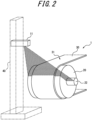
- FIG. 2 illustrates the measurement of the surface shape of a conveyor belt 30 of a belt conveyor 1 by a belt surface measurement apparatus 11 of the surface shape measurement apparatus 10.
- the surface shape measurement apparatus 10 measures the surface shape of the conveyor belt 30 wound around a pulley 20, as illustrated in FIG. 2 .
- the pulley 20 is an example of drive means.
- the conveyor belt 30 is an example of a belt.
- the surface shape measurement apparatus 10 is an apparatus that measures the surface shape of a belt driven in a travel direction by drive means.
- the belt is not limited to the conveyor belt 30, but in the present embodiment, the belt is described as being the conveyor belt 30 driven by the pulley 20.
- the travel direction is the direction in which the belt moves as a result of the driving force from the drive means.
- the travel direction is also referred to as the conveyance direction.
- the conveyance direction is the direction in which the conveyed material loaded on a surface 31 of the operating conveyor belt 30 moves.
- the thickness of the conveyor belt 30 needs to be controlled to prevent the conveyor belt 30 from breaking.
- the thickness of the conveyor belt 30 can be calculated and managed from the surface shape measured by the surface shape measurement apparatus 10. If the surface shape can be accurately measured, the thickness of the conveyor belt 30 can be accurately obtained by calculation.
- the surface shape is the shape, including unevenness, of the surface 31 of the conveyor belt 30. For example, an area, on the surface 31 of the conveyor belt 30, that is recessed compared to the surroundings can indicate that the conveyor belt 30 is thinner at that area than the surroundings.
- the surface shape measurement apparatus 10 includes the belt surface measurement apparatus 11 and a control unit 15.
- the control unit 15 includes a calculation apparatus 12 and an analysis apparatus 14.
- the surface shape measurement apparatus 10 is an apparatus that measures the surface shape of the conveyor belt 30 by the belt surface measurement apparatus 11, the calculation apparatus 12, and the analysis apparatus 14 operating in coordination.
- the calculation apparatus 12 obtains conveyor belt operating information 13 as needed.
- the conveyor belt operation information 13 is information about the operation and condition of the conveyor belt 30 and is, for example, obtained from a control unit of the belt conveyor 1.
- the belt surface measurement apparatus 11 and the control unit 15 may be connected by a network, such as a local area network (LAN), to transmit and receive information (measurement data) obtained by measurement.
- the control unit of the belt conveyor 1 may also be connected by a network, such as the same LAN. Details on the components of the surface shape measurement apparatus 10 are described below.
- the conveyor belt 30, which is the measurement target of the surface shape measurement apparatus 10, is wound around the pulley 20.
- the conveyor belt 30 moves and can convey objects placed on the surface 31 of the conveyor belt 30.
- the surface 31 of the conveyor belt 30 is the opposite side (outer side) of the conveyor belt 30 from the side by the pulley 20 (inner side).
- the belt surface measurement apparatus 11 measures the surface shape of the conveyor belt 30 and the pulley 20.
- the belt surface measurement apparatus 11 can identify the surface position of the conveyor belt 30 and the pulley 20 by measurement. In other words, local information on the surface shape can be considered to be the surface position. For this reason, the measurement by the belt surface measurement apparatus 11 is also referred to below as "measuring the surface position".
- the belt surface measurement apparatus 11 can simultaneously measure the surface position of the conveyor belt 30 and the surface position of the pulley 20 at a section at which the conveyor belt 30 contacts the pulley 20.
- the belt surface measurement apparatus 11 is a non-contact measurement apparatus that measures the surface position of the conveyor belt 30 and the pulley 20 in a non-contact state with respect to the conveyor belt 30 and the pulley 20.
- the belt surface measurement apparatus 11 performs measurements while the pulley 20 and the conveyor belt 30 are rotating.
- the belt surface measurement apparatus 11 preferably measures the surface position of at least the total length of the conveyor belt 30 in the conveyance direction.
- the belt surface measurement apparatus 11 is an apparatus based on a laser light cutting system, such as an optical cutting shape meter.
- the belt surface measurement apparatus 11 can measure the surface position of the total length of the conveyor belt 30 in the width direction by irradiating the conveyor belt 30 and the pulley 20 with a line laser beam.
- the belt surface measurement apparatus 11 can measure surface positions of both widthwise ends of the pulley 20, the widthwise ends being exposed from respective widthwise edges of the conveyor belt 30.
- the belt surface measurement apparatus 11 is installed at a position enabling irradiation of a laser beam onto the conveyor belt 30 from diagonally above the pulley 20, so that the surface positions of the conveyor belt 30 and the pulley 20 can be measured simultaneously at the section at which the conveyor belt 30 contacts the pulley 20.
- the belt surface measurement apparatus 11 may be configured to be held near the pulley 20 by a holding member 40 installed on the ground. In order to accurately measure the thickness direction of the conveyor belt 30, the belt surface measurement apparatus 11 is installed so that the irradiation direction of the laser beam passes through a center 22 of the pulley 20.
- the belt surface measurement apparatus 11 measures the surface position of the conveyor belt 30 at the section in contact with the pulley 20, the conveyor belt 30 does not swing up and down and can be measured in a stable position.
- the surface position of the conveyor belt 30 and the surface position of the pulley 20 can be measured simultaneously at the same location. Therefore, as compared to a configuration in which the surface positions of the conveyor belt 30 and the pulley 20 are measured separately by two measurement apparatuses, the number of measurement apparatuses can be reduced and the surface position of the conveyor belt 30 can be accurately corrected according to the surface position of the pulley 20.
- the belt surface measurement apparatus 11 can make measurements to obtain information on the surface position of the conveyor belt 30 and information on the surface position of the pulley 20.
- the resulting information on the surface position of the conveyor belt 30 includes the eccentricity and inclination of the pulley 20.
- the belt surface measurement apparatus 11 can be an apparatus that is not based on a laser light cutting system.
- the belt surface measurement apparatus 11 is preferably a non-contact measurement apparatus that can make measurements in a non-contact state with respect to the conveyor belt 30 and the pulley 20, so that the surface position of the conveyor belt 30 and the pulley 20 can be measured while the pulley 20 and the conveyor belt 30 are rotating.
- the control unit 15 is configured to include the calculation apparatus 12 and the analysis apparatus 14.
- the control unit 15 corrects the surface position of the conveyor belt 30 based on the surface position of the pulley 20 measured by the belt surface measurement apparatus 11 and calculates the surface shape of the conveyor belt 30.
- the control unit 15 may include a processor that performs calculations and a memory that stores data (such as information on surface positions) used in the calculations.
- the processor can, for example, be a general-purpose processor or a dedicated processor specialized for particular processing, but the processor is not limited to these examples and may be any processor.
- the memory includes one or more memories.
- the memories can be any memory, including but not limited to a semiconductor memory, a magnetic memory, or an optical memory.
- the control unit 15 may, for example, be a computer.
- the calculation apparatus 12 calculates the surface shape of the total length of the conveyor belt 30 in the conveyance direction based on the measurement data, which is information on the surface position from the belt surface measurement apparatus 11, and the conveyor belt operating information 13, which is acquired as necessary.
- the total length of the conveyor belt 30 in the conveyance direction is sometimes referred to as the total circumference or the total circumferential length.
- the calculation of the surface shape may include determining the thickness of the conveyor belt 30 and may also include determining the unevenness of the surface 31 of the conveyor belt 30, for example by mapping the unevenness to a two-dimensional map.
- the analysis apparatus 14 is an apparatus for obtaining the precise surface shape of the conveyor belt 30 by removing information on the surface position (eccentricity and inclination) of the pulley 20 from the information on the surface shape of the conveyor belt 30 as calculated by the calculation apparatus 12.
- the surface position of the pulley 20 that is to be removed is the surface position of the total width (total widthwise length) of the pulley 20.
- the analysis apparatus 14 estimates the surface position of a portion of the pulley 20 other than the widthwise ends of the pulley 20 (the total widthwise length) from the surface positions of both widthwise ends of the pulley 20 as measured by the belt surface measurement apparatus 11.
- the analysis apparatus 14 estimates the surface position of the pulley 20 as a linear portion of the pulley 20 in a case in which the positions of both widthwise ends of the pulley 20 are connected by a straight line, as illustrated by the dashed line in FIG. 5A , for example.
- the analysis apparatus 14 estimates the total widthwise length of the pulley 20 from the measured surface positions of both widthwise ends of the pulley 20 in the present embodiment, but the analysis apparatus 14 may make a partial estimation (discrete estimation) of the pulley 20 in the width direction.
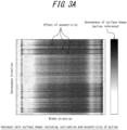
- FIGS. 3A and 3B illustrate the surface shapes of the conveyor belt 30 and the pulley 20 as a gray scale for the measurement data obtained by the belt surface measurement apparatus 11.
- the surface position is obtained as the position (hereinafter "height") in the height direction, taking the height direction to be the radial direction from the center 22 of the cylindrical pulley 20.
- the surface position of the conveyor belt 30 may be described as high in a case of being far from the center 22 and low in a case of being close to the center 22 in the radial direction of the pulley 20.
- black areas such as near the center in the width direction, indicate a higher surface position than white areas.
- FIG. 3A is data including the effects of inclination and eccentricity of the pulley 20.
- black linear areas can be seen along the entire length in the width direction.
- FIG. 3B is data without the effects of inclination and eccentricity of the pulley 20.
- black linear areas and asymmetric color distribution are not observed. Execution of the correction process described below yields data, on the surface shape of the conveyor belt 30 and the pulley 20, like the data illustrated in FIG. 3B .
- FIG. 4 is a flowchart illustrating an example of a surface shape measurement method executed by the surface shape measurement apparatus 10 according to the present embodiment.
- the surface shape measurement apparatus 10 waits in a case of determining, based on a signal obtained from the conveyor belt operation information 13, that the conveyor belt 30 is not in operation (No in step S1). If the conveyor belt 30 is in operation (Yes in step S1), the surface shape measurement apparatus 10 performs measurements using the belt surface measurement apparatus 11 (step S2).
- the surface shape measurement apparatus 10 then identifies the position of the conveyor belt 30 in the conveyance direction from the conveyor belt operating information 13 and stores the measurement data measured by the belt surface measurement apparatus 11 in correspondence with the identified position of the conveyor belt 30.
- the surface shape measurement apparatus 10 continues the measurement.
- the surface shape measurement apparatus 10 combines the data for one lap based on the information on the corresponding position of the conveyor belt 30 in the conveyance direction (step S4).
- the surface shape measurement apparatus 10 may select any of the measurement data, for example, or may calculate an average or the like and map the post-calculation measurement data to that position.
- the surface shape data obtained in step S3 includes the effect of the surface position (inclination and eccentricity) of the pulley 20. Therefore, the surface shape measurement apparatus 10 analyzes the correct surface shape data of the conveyor belt 30 (step S5). The surface shape measurement apparatus 10 corrects the surface position of the conveyor belt 30 based on the surface position (inclination and eccentricity) of the pulley 20 and calculates the surface shape of the conveyor belt 30 from which the effect of the inclination and eccentricity of the pulley 20 has been removed.
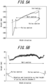
- FIGS. 5A and 5B are diagrams illustrating a method for correcting for the effect of inclination of the pulley 20.
- the pulley 20 and the conveyor belt 30 wrapped around the pulley 20 can be distinguished in the width direction because a sharp height difference (step) occurs at both ends (boundaries) of the conveyor belt 30.
- the pulley section in FIGS. 5A and 5B is the area where the pulley 20 is identified as being exposed.
- the belt section in FIGS. 5A and 5B is the area where the conveyor belt 30 is determined to be present.
- FIG. 5A illustrates an example of the surface position (surface shape) of the conveyor belt 30 before correction for inclination as calculated by the control unit 15.
- the difference in surface position (height) of the two ends of the pulley 20 indicates that the entire pulley is inclined in the width direction.
- the surface position (surface shape) of the conveyor belt 30 is also inclined due to the effect of inclination of the pulley 20.
- the control unit 15 corrects for the effect of inclination of the pulley 20 by rotating and translating the surface positions of the conveyor belt 30 and the pulley 20 so that the height of pulley 20 becomes 0 (reference point), as illustrated in FIG. 5B .
- the inclination of the pulley 20 can be measured (estimated) even while the pulley 20 (conveyor belt 30) is stopped.
- FIGS. 6A and 6B are diagrams illustrating a correction method in the case in which the pulley 20 has eccentricity (i.e., the center 22 is off). Due to the eccentricity of the pulley 20, the surface shape of the conveyor belt 30 becomes uneven in the conveyance direction (circumferential direction).
- the distance in the conveyance direction on the horizontal axis indicates the position, in the conveyance direction, at which the surface shape (height) of the conveyor belt 30 is measured, in terms of distance from the reference position on the conveyor belt 30, and is indicated as a length between 0 and 1 lap (total circumferential length).
- FIG. 6A illustrates the respective surface shapes of the center position of the conveyor belt 30 in the width direction and both widthwise end positions of the pulley 20 before eccentricity correction as calculated by the control unit 15.
- the moving average of the surface shape (profile of the belt section) of the conveyor belt 30 at the widthwise center and the moving average of the surface shape (profile of the pulley section) at both widthwise end positions of the pulley 20 coincide. This means that the surface shape of the belt section is affected by the eccentricity of the pulley 20.
- the control unit 15 corrects for the effect of eccentricity of the pulley 20 by subtracting the profile of the pulley section from the profile of the belt section to calculate the difference, as illustrated in FIG. 6B .
- FIG. 6B illustrates the respective surface shapes of the center position of the conveyor belt 30 in the width direction and both widthwise end positions of the pulley 20 before eccentricity correction as calculated by the control unit 15.
- the range of variation in the surface shape of the conveyor belt 30 is approximately 2 mm. Compared to the approximately 8 mm variation in the surface shape of the conveyor belt 30 before eccentricity correction ( FIG. 6A ), the variation is much smaller, indicating that the surface shape of the conveyor belt 30 can be accurately measured by the correction.
- the control unit 15 can then accurately measure the thickness of the conveyor belt 30 based on the surface shape of the conveyor belt 30 obtained accurately by correction.
- the conveyor belt 30 can be managed (monitored) based on the calculated surface shape of the conveyor belt 30.
- the surface shape measurement apparatus 10 determines whether the conveyor belt 30 is sufficiently thick based, for example, on the calculated surface shape of the conveyor belt 30. In a case of determining that the thickness is not sufficient, the surface shape measurement apparatus 10 can inform the operator of an abnormality in the conveyor belt 30 or stop the conveyor belt 30. In this way, management of the conveyor belt 30 based on the calculated surface shape of the conveyor belt 30 makes it possible accurately to detect abnormalities in the conveyor belt 30 and to respond promptly to abnormalities.
- the surface shape measurement apparatus 10 and surface shape measurement method according to the present embodiment can accurately measure the thickness of the conveyor belt 30, since the above-described configuration and processes can remove the effect of inclination and eccentricity of the pulley 20.
- the belt management method according to the present embodiment also makes it possible accurately to determine the thickness of the conveyor belt 30 and to manage the conveyor belt 30 to prevent breakage or the like.
- the measurement target is the conveyor belt 30, but the measurement target is not limited to the conveyor belt 30. It suffices for the belt that is the measurement target to be a belt that is wound around the pulley 20.
Landscapes
- Physics & Mathematics (AREA)
- General Physics & Mathematics (AREA)
- Engineering & Computer Science (AREA)
- Computer Vision & Pattern Recognition (AREA)
- Length Measuring Devices By Optical Means (AREA)
- Length Measuring Devices With Unspecified Measuring Means (AREA)
Abstract
Description
- The present disclosure relates to a surface shape measurement apparatus, a surface shape measurement method, and a belt management method. The present disclosure relates in particular to a surface shape measurement apparatus, a surface shape measurement method, and a belt management method that measure the surface shape of a belt wound around a pulley.
- A belt conveyor equipped with a conveyor belt wound around a pair of pulleys as drive means, for example, is known as a conveyor apparatus for conveying materials such as raw materials. In a belt conveyor, the thickness of the conveyor belt needs to be controlled to prevent the conveyor belt from breaking.
- Here, Patent Literature (PTL) 1 and 2, for example, disclose an apparatus and system for measuring the surface roughness of a conveyor belt by an optical cutting method using a line laser.
-
- PTL 1:
JP 2017-32346 A - PTL 2:
JP 2020-76767 A - In the technology of
PTL 1, the unevenness of the conveyor belt is measured at a distance from the pulleys, which tends to make the conveyor belt unstable, such as by swinging up and down. This makes it difficult to improve the measurement accuracy of the unevenness of the conveyor belt. On the other hand, the technology inPTL 2 measures the unevenness of the conveyor belt at a section at which the conveyor belt contacts the pulley. However, if the pulley around which the conveyor belt is wound is eccentric or inclined, the thickness of the conveyor belt cannot be accurately measured. - In light of these problems, it is an aim of the present disclosure to provide a surface shape measurement apparatus, a surface shape measurement method, and a belt management method that accurately measure the thickness of a belt.
-
- (1) A surface shape measurement apparatus according to an embodiment of the present disclosure is
- a surface shape measurement apparatus for measuring a surface shape of a belt wound around a pulley, the surface shape measurement apparatus including:
- a belt surface measurement apparatus configured to measure a surface position of the belt and a surface position of the pulley at a section at which the belt contacts the pulley; and
- a control unit configured to correct the surface position of the belt based on the measured surface position of the pulley and calculate the surface shape of the belt.
- (2) As an embodiment of the present disclosure, in (1),
- the belt surface measurement apparatus is configured to measure surface positions of both widthwise ends of the pulley, the widthwise ends being exposed from respective widthwise edges of the belt, and
- the control unit is configured to estimate a surface position of a portion of the pulley other than the widthwise ends of the pulley from the surface positions of both widthwise ends of the pulley and correct the surface position of the belt based on the estimated surface position of the pulley.
- (3) As an embodiment of the present disclosure, in (1) or (2),
the belt surface measurement apparatus is configured to measure a surface position of at least a total length of the belt in a conveyance direction. - (4) As an embodiment of the present disclosure, in any one of (1) to (3),
the control unit is configured to estimate an inclination of the pulley in a width direction from the surface position of the pulley and correct the surface position of the belt based on the inclination. - (5) As an embodiment of the present disclosure, in any one of (1) to (4),
the control unit is configured to estimate an eccentricity of the pulley in a circumferential direction from the surface position of the pulley and correct the surface position of the belt based on the eccentricity. - (6) A surface shape measurement method according to an embodiment of the present disclosure is
- a surface shape measurement method for measuring a surface shape of a belt wound around a pulley, the surface shape measurement method including:
- measuring a surface position of the belt and a surface position of the pulley at a section at which the belt contacts the pulley; and
- correcting the surface position of the belt based on the measured surface position of the pulley and calculating the surface shape of the belt.
- (7) A belt management method according to an embodiment of the present disclosure includes
managing a belt based on a surface shape of the belt calculated by the surface shape measurement method of (6). - According to the present disclosure, a surface shape measurement apparatus, a surface shape measurement method, and a belt management method that accurately measure the thickness of a belt can be provided.
- In the accompanying drawings:
-
FIG. 1 is a diagram illustrating an example configuration of a surface shape measurement apparatus according to an embodiment; -
FIG. 2 is a diagram illustrating measurement of the surface shape (surface position) of a conveyor belt by a belt surface measurement apparatus; -
FIG. 3A is a diagram illustrating the effect of inclination and eccentricity of a pulley on surface shape data of the conveyor belt; -
FIG. 3B is a diagram illustrating the effect of inclination and eccentricity of the pulley on surface shape data of the conveyor belt; -
FIG. 4 is a flowchart illustrating an example of a surface shape measurement method according to an embodiment; -
FIG. 5A is a diagram illustrating a method to correct for the effect of inclination of the pulley; -
FIG. 5B is a diagram illustrating a method to correct for the effect of inclination of the pulley; -
FIG. 6A is a diagram illustrating a method to correct for the effect of eccentricity of the pulley; and -
FIG. 6B is a diagram illustrating a method to correct for the effect of eccentricity of the pulley. - A surface shape measurement apparatus, a surface shape measurement method, and a belt management method according to an embodiment of the present disclosure will be described below with reference to the drawings. In each figure, identical or equivalent parts are marked with the same symbol. In the description of the present embodiment, a description of identical or equivalent parts will be omitted or simplified as appropriate.
-
FIG. 1 illustrates an example of the configuration of a surfaceshape measurement apparatus 10.FIG. 2 illustrates the measurement of the surface shape of aconveyor belt 30 of abelt conveyor 1 by a beltsurface measurement apparatus 11 of the surfaceshape measurement apparatus 10. The surfaceshape measurement apparatus 10 measures the surface shape of theconveyor belt 30 wound around apulley 20, as illustrated inFIG. 2 . Here, thepulley 20 is an example of drive means. Theconveyor belt 30 is an example of a belt. The surfaceshape measurement apparatus 10 is an apparatus that measures the surface shape of a belt driven in a travel direction by drive means. The belt is not limited to theconveyor belt 30, but in the present embodiment, the belt is described as being theconveyor belt 30 driven by thepulley 20. Here, the travel direction is the direction in which the belt moves as a result of the driving force from the drive means. In the present embodiment, the travel direction is also referred to as the conveyance direction. The conveyance direction is the direction in which the conveyed material loaded on asurface 31 of the operatingconveyor belt 30 moves. - In the
belt conveyor 1, the thickness of theconveyor belt 30 needs to be controlled to prevent theconveyor belt 30 from breaking. The thickness of theconveyor belt 30 can be calculated and managed from the surface shape measured by the surfaceshape measurement apparatus 10. If the surface shape can be accurately measured, the thickness of theconveyor belt 30 can be accurately obtained by calculation. The surface shape is the shape, including unevenness, of thesurface 31 of theconveyor belt 30. For example, an area, on thesurface 31 of theconveyor belt 30, that is recessed compared to the surroundings can indicate that theconveyor belt 30 is thinner at that area than the surroundings. - As illustrated in
FIG. 1 , the surfaceshape measurement apparatus 10 according to the present embodiment includes the beltsurface measurement apparatus 11 and acontrol unit 15. Thecontrol unit 15 includes acalculation apparatus 12 and ananalysis apparatus 14. The surfaceshape measurement apparatus 10 is an apparatus that measures the surface shape of theconveyor belt 30 by the beltsurface measurement apparatus 11, thecalculation apparatus 12, and theanalysis apparatus 14 operating in coordination. Thecalculation apparatus 12 obtains conveyorbelt operating information 13 as needed. The conveyorbelt operation information 13 is information about the operation and condition of theconveyor belt 30 and is, for example, obtained from a control unit of thebelt conveyor 1. The beltsurface measurement apparatus 11 and thecontrol unit 15 may be connected by a network, such as a local area network (LAN), to transmit and receive information (measurement data) obtained by measurement. The control unit of thebelt conveyor 1 may also be connected by a network, such as the same LAN. Details on the components of the surfaceshape measurement apparatus 10 are described below. - As illustrated in
FIG. 2 , theconveyor belt 30, which is the measurement target of the surfaceshape measurement apparatus 10, is wound around thepulley 20. When thepulley 20 rotates, theconveyor belt 30 moves and can convey objects placed on thesurface 31 of theconveyor belt 30. Thesurface 31 of theconveyor belt 30 is the opposite side (outer side) of theconveyor belt 30 from the side by the pulley 20 (inner side). - As illustrated in
FIG. 2 , the beltsurface measurement apparatus 11 measures the surface shape of theconveyor belt 30 and thepulley 20. The beltsurface measurement apparatus 11 can identify the surface position of theconveyor belt 30 and thepulley 20 by measurement. In other words, local information on the surface shape can be considered to be the surface position. For this reason, the measurement by the beltsurface measurement apparatus 11 is also referred to below as "measuring the surface position". The beltsurface measurement apparatus 11 can simultaneously measure the surface position of theconveyor belt 30 and the surface position of thepulley 20 at a section at which theconveyor belt 30 contacts thepulley 20. In the present embodiment, the beltsurface measurement apparatus 11 is a non-contact measurement apparatus that measures the surface position of theconveyor belt 30 and thepulley 20 in a non-contact state with respect to theconveyor belt 30 and thepulley 20. The beltsurface measurement apparatus 11 performs measurements while thepulley 20 and theconveyor belt 30 are rotating. The beltsurface measurement apparatus 11 preferably measures the surface position of at least the total length of theconveyor belt 30 in the conveyance direction. - In the present embodiment, the belt
surface measurement apparatus 11 is an apparatus based on a laser light cutting system, such as an optical cutting shape meter. The beltsurface measurement apparatus 11 can measure the surface position of the total length of theconveyor belt 30 in the width direction by irradiating theconveyor belt 30 and thepulley 20 with a line laser beam. The beltsurface measurement apparatus 11 can measure surface positions of both widthwise ends of thepulley 20, the widthwise ends being exposed from respective widthwise edges of theconveyor belt 30. - The belt
surface measurement apparatus 11 is installed at a position enabling irradiation of a laser beam onto theconveyor belt 30 from diagonally above thepulley 20, so that the surface positions of theconveyor belt 30 and thepulley 20 can be measured simultaneously at the section at which theconveyor belt 30 contacts thepulley 20. The beltsurface measurement apparatus 11 may be configured to be held near thepulley 20 by a holdingmember 40 installed on the ground. In order to accurately measure the thickness direction of theconveyor belt 30, the beltsurface measurement apparatus 11 is installed so that the irradiation direction of the laser beam passes through acenter 22 of thepulley 20. Since the beltsurface measurement apparatus 11 measures the surface position of theconveyor belt 30 at the section in contact with thepulley 20, theconveyor belt 30 does not swing up and down and can be measured in a stable position. The surface position of theconveyor belt 30 and the surface position of thepulley 20 can be measured simultaneously at the same location. Therefore, as compared to a configuration in which the surface positions of theconveyor belt 30 and thepulley 20 are measured separately by two measurement apparatuses, the number of measurement apparatuses can be reduced and the surface position of theconveyor belt 30 can be accurately corrected according to the surface position of thepulley 20. - In this way, the belt
surface measurement apparatus 11 can make measurements to obtain information on the surface position of theconveyor belt 30 and information on the surface position of thepulley 20. However, the resulting information on the surface position of theconveyor belt 30 includes the eccentricity and inclination of thepulley 20. - Here, as another configuration example, the belt
surface measurement apparatus 11 can be an apparatus that is not based on a laser light cutting system. However, the beltsurface measurement apparatus 11 is preferably a non-contact measurement apparatus that can make measurements in a non-contact state with respect to theconveyor belt 30 and thepulley 20, so that the surface position of theconveyor belt 30 and thepulley 20 can be measured while thepulley 20 and theconveyor belt 30 are rotating. - The
control unit 15 is configured to include thecalculation apparatus 12 and theanalysis apparatus 14. Thecontrol unit 15 corrects the surface position of theconveyor belt 30 based on the surface position of thepulley 20 measured by the beltsurface measurement apparatus 11 and calculates the surface shape of theconveyor belt 30. Thecontrol unit 15 may include a processor that performs calculations and a memory that stores data (such as information on surface positions) used in the calculations. The processor can, for example, be a general-purpose processor or a dedicated processor specialized for particular processing, but the processor is not limited to these examples and may be any processor. The memory includes one or more memories. The memories can be any memory, including but not limited to a semiconductor memory, a magnetic memory, or an optical memory. Thecontrol unit 15 may, for example, be a computer. - The
calculation apparatus 12 calculates the surface shape of the total length of theconveyor belt 30 in the conveyance direction based on the measurement data, which is information on the surface position from the beltsurface measurement apparatus 11, and the conveyorbelt operating information 13, which is acquired as necessary. The total length of theconveyor belt 30 in the conveyance direction is sometimes referred to as the total circumference or the total circumferential length. The calculation of the surface shape may include determining the thickness of theconveyor belt 30 and may also include determining the unevenness of thesurface 31 of theconveyor belt 30, for example by mapping the unevenness to a two-dimensional map. - The
analysis apparatus 14 is an apparatus for obtaining the precise surface shape of theconveyor belt 30 by removing information on the surface position (eccentricity and inclination) of thepulley 20 from the information on the surface shape of theconveyor belt 30 as calculated by thecalculation apparatus 12. Here, the surface position of thepulley 20 that is to be removed is the surface position of the total width (total widthwise length) of thepulley 20. Theanalysis apparatus 14 estimates the surface position of a portion of thepulley 20 other than the widthwise ends of the pulley 20 (the total widthwise length) from the surface positions of both widthwise ends of thepulley 20 as measured by the beltsurface measurement apparatus 11. Theanalysis apparatus 14 estimates the surface position of thepulley 20 as a linear portion of thepulley 20 in a case in which the positions of both widthwise ends of thepulley 20 are connected by a straight line, as illustrated by the dashed line inFIG. 5A , for example. Here, theanalysis apparatus 14 estimates the total widthwise length of thepulley 20 from the measured surface positions of both widthwise ends of thepulley 20 in the present embodiment, but theanalysis apparatus 14 may make a partial estimation (discrete estimation) of thepulley 20 in the width direction. -
FIGS. 3A and3B illustrate the surface shapes of theconveyor belt 30 and thepulley 20 as a gray scale for the measurement data obtained by the beltsurface measurement apparatus 11. In the present embodiment, the surface position is obtained as the position (hereinafter "height") in the height direction, taking the height direction to be the radial direction from thecenter 22 of thecylindrical pulley 20. The surface position of theconveyor belt 30 may be described as high in a case of being far from thecenter 22 and low in a case of being close to thecenter 22 in the radial direction of thepulley 20. InFIGS. 3A and3B , black areas, such as near the center in the width direction, indicate a higher surface position than white areas.FIG. 3A is data including the effects of inclination and eccentricity of thepulley 20. For example, due to the effect of eccentricity, black linear areas can be seen along the entire length in the width direction. In addition, a color distribution that is not symmetrical with respect to the width direction is observed.FIG. 3B is data without the effects of inclination and eccentricity of thepulley 20. InFIG. 3B , black linear areas and asymmetric color distribution are not observed. Execution of the correction process described below yields data, on the surface shape of theconveyor belt 30 and thepulley 20, like the data illustrated inFIG. 3B . -
FIG. 4 is a flowchart illustrating an example of a surface shape measurement method executed by the surfaceshape measurement apparatus 10 according to the present embodiment. - The surface
shape measurement apparatus 10 waits in a case of determining, based on a signal obtained from the conveyorbelt operation information 13, that theconveyor belt 30 is not in operation (No in step S1). If theconveyor belt 30 is in operation (Yes in step S1), the surfaceshape measurement apparatus 10 performs measurements using the belt surface measurement apparatus 11 (step S2). - The surface
shape measurement apparatus 10 then identifies the position of theconveyor belt 30 in the conveyance direction from the conveyorbelt operating information 13 and stores the measurement data measured by the beltsurface measurement apparatus 11 in correspondence with the identified position of theconveyor belt 30. - If the surface position of the
conveyor belt 30 has not been measured over the total length (one lap) in the conveyance direction (No in step S3), the surfaceshape measurement apparatus 10 continues the measurement. In a case in which data for one lap of theconveyor belt 30 has been measured (Yes in step S3), the surfaceshape measurement apparatus 10 combines the data for one lap based on the information on the corresponding position of theconveyor belt 30 in the conveyance direction (step S4). Here, there may be a plurality of points of measurement data at one location. The surfaceshape measurement apparatus 10 may select any of the measurement data, for example, or may calculate an average or the like and map the post-calculation measurement data to that position. - Here, the surface shape data obtained in step S3 includes the effect of the surface position (inclination and eccentricity) of the
pulley 20. Therefore, the surfaceshape measurement apparatus 10 analyzes the correct surface shape data of the conveyor belt 30 (step S5). The surfaceshape measurement apparatus 10 corrects the surface position of theconveyor belt 30 based on the surface position (inclination and eccentricity) of thepulley 20 and calculates the surface shape of theconveyor belt 30 from which the effect of the inclination and eccentricity of thepulley 20 has been removed. -
FIGS. 5A and 5B are diagrams illustrating a method for correcting for the effect of inclination of thepulley 20. Here, thepulley 20 and theconveyor belt 30 wrapped around thepulley 20 can be distinguished in the width direction because a sharp height difference (step) occurs at both ends (boundaries) of theconveyor belt 30. The pulley section inFIGS. 5A and 5B is the area where thepulley 20 is identified as being exposed. The belt section inFIGS. 5A and 5B is the area where theconveyor belt 30 is determined to be present.FIG. 5A illustrates an example of the surface position (surface shape) of theconveyor belt 30 before correction for inclination as calculated by thecontrol unit 15. The difference in surface position (height) of the two ends of thepulley 20 indicates that the entire pulley is inclined in the width direction. The surface position (surface shape) of theconveyor belt 30 is also inclined due to the effect of inclination of thepulley 20. Thecontrol unit 15 corrects for the effect of inclination of thepulley 20 by rotating and translating the surface positions of theconveyor belt 30 and thepulley 20 so that the height ofpulley 20 becomes 0 (reference point), as illustrated inFIG. 5B . Here, the inclination of thepulley 20 can be measured (estimated) even while the pulley 20 (conveyor belt 30) is stopped. -
FIGS. 6A and 6B are diagrams illustrating a correction method in the case in which thepulley 20 has eccentricity (i.e., thecenter 22 is off). Due to the eccentricity of thepulley 20, the surface shape of theconveyor belt 30 becomes uneven in the conveyance direction (circumferential direction). Here, the distance in the conveyance direction on the horizontal axis indicates the position, in the conveyance direction, at which the surface shape (height) of theconveyor belt 30 is measured, in terms of distance from the reference position on theconveyor belt 30, and is indicated as a length between 0 and 1 lap (total circumferential length).FIG. 6A illustrates the respective surface shapes of the center position of theconveyor belt 30 in the width direction and both widthwise end positions of thepulley 20 before eccentricity correction as calculated by thecontrol unit 15. The moving average of the surface shape (profile of the belt section) of theconveyor belt 30 at the widthwise center and the moving average of the surface shape (profile of the pulley section) at both widthwise end positions of thepulley 20 coincide. This means that the surface shape of the belt section is affected by the eccentricity of thepulley 20. Thecontrol unit 15 corrects for the effect of eccentricity of thepulley 20 by subtracting the profile of the pulley section from the profile of the belt section to calculate the difference, as illustrated inFIG. 6B . In the example inFIG. 6B , the range of variation in the surface shape of theconveyor belt 30 is approximately 2 mm. Compared to the approximately 8 mm variation in the surface shape of theconveyor belt 30 before eccentricity correction (FIG. 6A ), the variation is much smaller, indicating that the surface shape of theconveyor belt 30 can be accurately measured by the correction. Thecontrol unit 15 can then accurately measure the thickness of theconveyor belt 30 based on the surface shape of theconveyor belt 30 obtained accurately by correction. - Using the above-described surface shape measurement method, the
conveyor belt 30 can be managed (monitored) based on the calculated surface shape of theconveyor belt 30. The surfaceshape measurement apparatus 10 determines whether theconveyor belt 30 is sufficiently thick based, for example, on the calculated surface shape of theconveyor belt 30. In a case of determining that the thickness is not sufficient, the surfaceshape measurement apparatus 10 can inform the operator of an abnormality in theconveyor belt 30 or stop theconveyor belt 30. In this way, management of theconveyor belt 30 based on the calculated surface shape of theconveyor belt 30 makes it possible accurately to detect abnormalities in theconveyor belt 30 and to respond promptly to abnormalities. - As described above, the surface
shape measurement apparatus 10 and surface shape measurement method according to the present embodiment can accurately measure the thickness of theconveyor belt 30, since the above-described configuration and processes can remove the effect of inclination and eccentricity of thepulley 20. The belt management method according to the present embodiment also makes it possible accurately to determine the thickness of theconveyor belt 30 and to manage theconveyor belt 30 to prevent breakage or the like. - While embodiments of the present disclosure have been described with reference to the drawings and examples, it should be noted that various modifications and amendments may easily be implemented by those skilled in the art based on the present disclosure. Accordingly, such modifications and amendments are included within the scope of the present disclosure. For example, functions or the like included in each component, each step (process), or the like can be rearranged without logical inconsistency, and a plurality of components, steps, or the like can be combined into one or divided. Embodiments according to the present disclosure can also be realized as a program executed by a processor included in an apparatus or as a storage medium having the program recorded thereon. Such embodiments are also to be understood as included in the scope of the present disclosure.
- In the above embodiment, the measurement target is the
conveyor belt 30, but the measurement target is not limited to theconveyor belt 30. It suffices for the belt that is the measurement target to be a belt that is wound around thepulley 20. -
- 1
- Belt conveyor
- 10
- Surface shape measurement apparatus
- 11
- Belt surface measurement apparatus
- 12
- Calculation apparatus
- 13
- Conveyor belt operation information
- 14
- Analysis apparatus
- 60
- Control unit
- 20
- Pulley
- 22
- Center
- 30
- Conveyor belt
- 31
- Surface of conveyor belt
- 40
- Holding member
Claims (7)
- A surface shape measurement apparatus for measuring a surface shape of a belt wound around a pulley, the surface shape measurement apparatus comprising:a belt surface measurement apparatus configured to measure a surface position of the belt and a surface position of the pulley at a section at which the belt contacts the pulley; anda control unit configured to correct the surface position of the belt based on the measured surface position of the pulley and calculate the surface shape of the belt.
- The surface shape measurement apparatus according to claim 1, wherein the belt surface measurement apparatus is configured to measure surface positions of both widthwise ends of the pulley, the widthwise ends being exposed from respective widthwise edges of the belt, and
the control unit is configured to estimate a surface position of a portion of the pulley other than the widthwise ends of the pulley from the surface positions of both widthwise ends of the pulley and correct the surface position of the belt based on the estimated surface position of the pulley. - The surface shape measurement apparatus according to claim 1 or 2, wherein the belt surface measurement apparatus is configured to measure a surface position of at least a total length of the belt in a conveyance direction.
- The surface shape measurement apparatus according to any one of claims 1 to 3, wherein the control unit is configured to estimate an inclination of the pulley in a width direction from the surface position of the pulley and correct the surface position of the belt based on the inclination.
- The surface shape measurement apparatus according to any one of claims 1 to 4, wherein the control unit is configured to estimate an eccentricity of the pulley in a circumferential direction from the surface position of the pulley and correct the surface position of the belt based on the eccentricity.
- A surface shape measurement method for measuring a surface shape of a belt wound around a pulley, the surface shape measurement method comprising:measuring a surface position of the belt and a surface position of the pulley at a section at which the belt contacts the pulley; andcorrecting the surface position of the belt based on the measured surface position of the pulley and calculating the surface shape of the belt.
- A belt management method comprising managing a belt based on a surface shape of the belt calculated by the surface shape measurement method according to claim 6.
Applications Claiming Priority (2)
| Application Number | Priority Date | Filing Date | Title |
|---|---|---|---|
| JP2022065346 | 2022-04-11 | ||
| PCT/JP2023/009732 WO2023199679A1 (en) | 2022-04-11 | 2023-03-13 | Surface shape measurement device, surface shape measurement method, and belt management method |
Publications (2)
| Publication Number | Publication Date |
|---|---|
| EP4474764A1 true EP4474764A1 (en) | 2024-12-11 |
| EP4474764A4 EP4474764A4 (en) | 2025-05-07 |
Family
ID=88329428
Family Applications (1)
| Application Number | Title | Priority Date | Filing Date |
|---|---|---|---|
| EP23788101.6A Pending EP4474764A4 (en) | 2022-04-11 | 2023-03-13 | Surface shape measurement device, surface shape measurement method, and belt management method |
Country Status (5)
| Country | Link |
|---|---|
| EP (1) | EP4474764A4 (en) |
| JP (1) | JP7736064B2 (en) |
| KR (1) | KR20240145000A (en) |
| CN (1) | CN119173734A (en) |
| WO (1) | WO2023199679A1 (en) |
Family Cites Families (7)
| Publication number | Priority date | Publication date | Assignee | Title |
|---|---|---|---|---|
| JPH11248425A (en) * | 1998-03-03 | 1999-09-17 | Bridgestone Corp | Device for measuring sheet thickness |
| JP2006132942A (en) * | 2004-11-02 | 2006-05-25 | Toyota Motor Corp | Belt surface deformation inspection device |
| KR101897835B1 (en) * | 2012-07-24 | 2018-09-12 | 삼성에스디아이 주식회사 | Web thickness measuring equipment and method |
| AU2014415595A1 (en) | 2014-12-30 | 2017-07-20 | Kimberly-Clark Worldwide, Inc. | Web caliper measurement and control system |
| JP6554355B2 (en) | 2015-07-30 | 2019-07-31 | 大成建設株式会社 | Belt conveyor monitoring system |
| WO2018076053A1 (en) * | 2016-10-24 | 2018-05-03 | Wearhawk Pty Ltd | Belt inspection system and method |
| JPWO2019188718A1 (en) * | 2018-03-28 | 2020-04-30 | バンドー化学株式会社 | Surface shape monitoring device, wear amount measuring system and surface shape monitoring system |
-
2023
- 2023-03-13 CN CN202380028304.6A patent/CN119173734A/en active Pending
- 2023-03-13 EP EP23788101.6A patent/EP4474764A4/en active Pending
- 2023-03-13 KR KR1020247029747A patent/KR20240145000A/en active Pending
- 2023-03-13 WO PCT/JP2023/009732 patent/WO2023199679A1/en not_active Ceased
- 2023-03-13 JP JP2023535078A patent/JP7736064B2/en active Active
Also Published As
| Publication number | Publication date |
|---|---|
| JP7736064B2 (en) | 2025-09-09 |
| JPWO2023199679A1 (en) | 2023-10-19 |
| CN119173734A (en) | 2024-12-20 |
| KR20240145000A (en) | 2024-10-04 |
| WO2023199679A1 (en) | 2023-10-19 |
| EP4474764A4 (en) | 2025-05-07 |
Similar Documents
| Publication | Publication Date | Title |
|---|---|---|
| EP4492001A1 (en) | Surface shape measurement apparatus, surface shape measurement method, and belt management method | |
| EP4492002A1 (en) | Surface shape measuring device, surface shape measuring method, and belt management method | |
| JP7736064B2 (en) | Surface profile measuring device, surface profile measuring method, and belt management method | |
| WO2023199681A1 (en) | Surface shape measuring device, surface shape measuring method, and belt management method | |
| EP4354080B1 (en) | Surface shape measurement device, surface shape measurement method, and conveyor belt management method | |
| JP7582550B2 (en) | Monitoring method and monitoring device | |
| JP7452752B2 (en) | Surface profile measurement method, surface profile measurement device, and belt management method | |
| JP6433824B2 (en) | Width direction end position detection method of strip-shaped member | |
| JP7806972B2 (en) | Surface profile measuring device and surface profile measuring method | |
| EP4589246A1 (en) | Surface shape measurement device and surface shape measurement method | |
| JP2004036048A (en) | Sheet material weight inspection system | |
| EP4360863B1 (en) | Tire building apparatus and method | |
| WO2025216029A1 (en) | Belt management device and belt management method | |
| WO2026079257A1 (en) | System and method for managing belt conveyor | |
| JP6433822B2 (en) | The width direction edge part position detection method of a strip | belt-shaped member. | |
| CN121247309A (en) | Multi-dimensional automatic deviation correcting method, device, product and medium for belt conveyor | |
| JPH11118433A (en) | Thickness measuring device and thickness measuring method |
Legal Events
| Date | Code | Title | Description |
|---|---|---|---|
| STAA | Information on the status of an ep patent application or granted ep patent |
Free format text: STATUS: THE INTERNATIONAL PUBLICATION HAS BEEN MADE |
|
| PUAI | Public reference made under article 153(3) epc to a published international application that has entered the european phase |
Free format text: ORIGINAL CODE: 0009012 |
|
| STAA | Information on the status of an ep patent application or granted ep patent |
Free format text: STATUS: REQUEST FOR EXAMINATION WAS MADE |
|
| 17P | Request for examination filed |
Effective date: 20240906 |
|
| AK | Designated contracting states |
Kind code of ref document: A1 Designated state(s): AL AT BE BG CH CY CZ DE DK EE ES FI FR GB GR HR HU IE IS IT LI LT LU LV MC ME MK MT NL NO PL PT RO RS SE SI SK SM TR |
|
| A4 | Supplementary search report drawn up and despatched |
Effective date: 20250404 |
|
| RIC1 | Information provided on ipc code assigned before grant |
Ipc: G01B 21/04 20060101ALI20250331BHEP Ipc: G01B 11/30 20060101ALI20250331BHEP Ipc: G01B 11/24 20060101ALI20250331BHEP Ipc: B65G 43/02 20060101ALI20250331BHEP Ipc: G01B 11/06 20060101ALI20250331BHEP Ipc: G01B 11/25 20060101AFI20250331BHEP |
|
| DAV | Request for validation of the european patent (deleted) | ||
| DAX | Request for extension of the european patent (deleted) |