EP4474748A1 - Loop heat pipe, housing assembly and electronic device - Google Patents
Loop heat pipe, housing assembly and electronic device Download PDFInfo
- Publication number
- EP4474748A1 EP4474748A1 EP24155818.8A EP24155818A EP4474748A1 EP 4474748 A1 EP4474748 A1 EP 4474748A1 EP 24155818 A EP24155818 A EP 24155818A EP 4474748 A1 EP4474748 A1 EP 4474748A1
- Authority
- EP
- European Patent Office
- Prior art keywords
- housing
- capillary structure
- passage
- heat pipe
- evaporation cavities
- Prior art date
- Legal status (The legal status is an assumption and is not a legal conclusion. Google has not performed a legal analysis and makes no representation as to the accuracy of the status listed.)
- Granted
Links
Images




Classifications
-
- F—MECHANICAL ENGINEERING; LIGHTING; HEATING; WEAPONS; BLASTING
- F28—HEAT EXCHANGE IN GENERAL
- F28D—HEAT-EXCHANGE APPARATUS, NOT PROVIDED FOR IN ANOTHER SUBCLASS, IN WHICH THE HEAT-EXCHANGE MEDIA DO NOT COME INTO DIRECT CONTACT
- F28D15/00—Heat-exchange apparatus with the intermediate heat-transfer medium in closed tubes passing into or through the conduit walls ; Heat-exchange apparatus employing intermediate heat-transfer medium or bodies
- F28D15/02—Heat-exchange apparatus with the intermediate heat-transfer medium in closed tubes passing into or through the conduit walls ; Heat-exchange apparatus employing intermediate heat-transfer medium or bodies in which the medium condenses and evaporates, e.g. heat pipes
- F28D15/04—Heat-exchange apparatus with the intermediate heat-transfer medium in closed tubes passing into or through the conduit walls ; Heat-exchange apparatus employing intermediate heat-transfer medium or bodies in which the medium condenses and evaporates, e.g. heat pipes with tubes having a capillary structure
- F28D15/043—Heat-exchange apparatus with the intermediate heat-transfer medium in closed tubes passing into or through the conduit walls ; Heat-exchange apparatus employing intermediate heat-transfer medium or bodies in which the medium condenses and evaporates, e.g. heat pipes with tubes having a capillary structure forming loops, e.g. capillary pumped loops
-
- F—MECHANICAL ENGINEERING; LIGHTING; HEATING; WEAPONS; BLASTING
- F28—HEAT EXCHANGE IN GENERAL
- F28D—HEAT-EXCHANGE APPARATUS, NOT PROVIDED FOR IN ANOTHER SUBCLASS, IN WHICH THE HEAT-EXCHANGE MEDIA DO NOT COME INTO DIRECT CONTACT
- F28D15/00—Heat-exchange apparatus with the intermediate heat-transfer medium in closed tubes passing into or through the conduit walls ; Heat-exchange apparatus employing intermediate heat-transfer medium or bodies
- F28D15/02—Heat-exchange apparatus with the intermediate heat-transfer medium in closed tubes passing into or through the conduit walls ; Heat-exchange apparatus employing intermediate heat-transfer medium or bodies in which the medium condenses and evaporates, e.g. heat pipes
- F28D15/0233—Heat-exchange apparatus with the intermediate heat-transfer medium in closed tubes passing into or through the conduit walls ; Heat-exchange apparatus employing intermediate heat-transfer medium or bodies in which the medium condenses and evaporates, e.g. heat pipes the conduits having a particular shape, e.g. non-circular cross-section, annular
-
- F—MECHANICAL ENGINEERING; LIGHTING; HEATING; WEAPONS; BLASTING
- F28—HEAT EXCHANGE IN GENERAL
- F28D—HEAT-EXCHANGE APPARATUS, NOT PROVIDED FOR IN ANOTHER SUBCLASS, IN WHICH THE HEAT-EXCHANGE MEDIA DO NOT COME INTO DIRECT CONTACT
- F28D15/00—Heat-exchange apparatus with the intermediate heat-transfer medium in closed tubes passing into or through the conduit walls ; Heat-exchange apparatus employing intermediate heat-transfer medium or bodies
- F28D15/02—Heat-exchange apparatus with the intermediate heat-transfer medium in closed tubes passing into or through the conduit walls ; Heat-exchange apparatus employing intermediate heat-transfer medium or bodies in which the medium condenses and evaporates, e.g. heat pipes
- F28D15/04—Heat-exchange apparatus with the intermediate heat-transfer medium in closed tubes passing into or through the conduit walls ; Heat-exchange apparatus employing intermediate heat-transfer medium or bodies in which the medium condenses and evaporates, e.g. heat pipes with tubes having a capillary structure
- F28D15/046—Heat-exchange apparatus with the intermediate heat-transfer medium in closed tubes passing into or through the conduit walls ; Heat-exchange apparatus employing intermediate heat-transfer medium or bodies in which the medium condenses and evaporates, e.g. heat pipes with tubes having a capillary structure characterised by the material or the construction of the capillary structure
-
- F—MECHANICAL ENGINEERING; LIGHTING; HEATING; WEAPONS; BLASTING
- F28—HEAT EXCHANGE IN GENERAL
- F28F—DETAILS OF HEAT-EXCHANGE AND HEAT-TRANSFER APPARATUS, OF GENERAL APPLICATION
- F28F9/00—Casings; Header boxes; Auxiliary supports for elements; Auxiliary members within casings
-
- H—ELECTRICITY
- H05—ELECTRIC TECHNIQUES NOT OTHERWISE PROVIDED FOR
- H05K—PRINTED CIRCUITS; CASINGS OR CONSTRUCTIONAL DETAILS OF ELECTRIC APPARATUS; MANUFACTURE OF ASSEMBLAGES OF ELECTRICAL COMPONENTS
- H05K7/00—Constructional details common to different types of electric apparatus
- H05K7/20—Modifications to facilitate cooling, ventilating, or heating
- H05K7/2029—Modifications to facilitate cooling, ventilating, or heating using a liquid coolant with phase change in electronic enclosures
- H05K7/20336—Heat pipes, e.g. wicks or capillary pumps
-
- F—MECHANICAL ENGINEERING; LIGHTING; HEATING; WEAPONS; BLASTING
- F28—HEAT EXCHANGE IN GENERAL
- F28D—HEAT-EXCHANGE APPARATUS, NOT PROVIDED FOR IN ANOTHER SUBCLASS, IN WHICH THE HEAT-EXCHANGE MEDIA DO NOT COME INTO DIRECT CONTACT
- F28D21/00—Heat-exchange apparatus not covered by any of the groups F28D1/00 - F28D20/00
- F28D2021/0019—Other heat exchangers for particular applications; Heat exchange systems not otherwise provided for
- F28D2021/0028—Other heat exchangers for particular applications; Heat exchange systems not otherwise provided for for cooling heat generating elements, e.g. for cooling electronic components or electric devices
-
- F—MECHANICAL ENGINEERING; LIGHTING; HEATING; WEAPONS; BLASTING
- F28—HEAT EXCHANGE IN GENERAL
- F28F—DETAILS OF HEAT-EXCHANGE AND HEAT-TRANSFER APPARATUS, OF GENERAL APPLICATION
- F28F21/00—Constructions of heat-exchange apparatus characterised by the selection of particular materials
- F28F21/08—Constructions of heat-exchange apparatus characterised by the selection of particular materials of metal
- F28F21/081—Heat exchange elements made from metals or metal alloys
- F28F21/084—Heat exchange elements made from metals or metal alloys from aluminium or aluminium alloys
Definitions
- the present disclosure relates to the field of electronic technology, and in particular to a loop heat pipe, a housing assembly and an electronic device.
- a loop heat pipe is usually used to improve heat dissipation efficiency.
- the loop heat pipe further improves the heat dissipation efficiency through a gas-liquid separation structure.
- the present disclosure provides a loop heat pipe, a housing assembly, and an electronic device.
- the loop heat pipe can dissipate heat from at least two heat sources separately, is easy to be manufactured, and can effectively reduce manufacturing cost.
- the housing assembly and the electronic device, with the use of the loop heat pipe, have good heat dissipation performance, which is beneficial to reducing the heat dissipation cost of the electronic device.
- a loop heat pipe including a housing component, a first capillary structure and a second capillary structure.
- the housing component is provided with a pipeline unit, a first partition part and at least two evaporation cavities.
- the pipeline unit is provided with a liquid replenishment passage, the at least two evaporation cavities are spaced apart in a length direction of the liquid replenishment passage, and two adjacent evaporation cavities are separated by the first partition part.
- At least one of the evaporation cavities includes a vapor outlet communicated with one end of the pipeline unit and a liquid replenishment port communicated with the liquid replenishment passage.
- At least part of the first capillary structure is disposed in the liquid replenishment passage and at least two evaporation cavities.
- the second capillary structure is disposed in at least one of the liquid replenishment passage and the evaporation cavities.
- the second capillary structure includes first bodies that correspond to the evaporation cavities on a one-to-one basis. At least one of the first bodies blocks the liquid replenishment port of the corresponding evaporation cavity, and at least part of the at least one of the first bodies is in contact with the first capillary structure.
- the loop heat pipe has at least two evaporation cavities and can dissipate heat from at least two heat sources. Two adjacent evaporation cavities are separated by the first partition part, so that the heat between the adjacent evaporation cavities does not interfere with each other.
- an anti-backflow structure can be formed. Accordingly, the liquid contained in the evaporation cavities is heated and evaporates into vapor, which flows out from the vapor outlets to the pipeline unit because the liquid replenishment ports are blocked. The vapor flows to a cold end through the pipeline unit and condenses into liquid, and then flows back to the liquid replenishment ports through the liquid replenishment passage.
- the second capillary structure will absorb the condensed liquid and transport it to the first capillary structure that is in contact with it, and replenish the liquid back to the evaporation cavities through the first capillary structure, which improves the heat dissipation performance of the loop heat pipe.
- the loop heat pipe can dissipate heat from at least two heat sources separately, and form the anti-backflow structure through the capillary structures, making it difficult for the vapor formed by evaporation to flow out from the replenishment ports, thereby achieving separation of gas and liquid in the loop heat pipe. Furthermore, it makes the loop heat pipe easy to be manufactured and implemented, which can effectively reduce manufacturing costs.
- the first bodies are stacked on the first capillary structure to block the liquid replenishment ports; or at least part of the first bodies is filled in the liquid replenishment passage to block the liquid replenishment ports.
- the loop heat pipe further includes a working medium disposed in the pipeline unit and the evaporation cavities, and the first bodies block the liquid replenishment ports to cause the working medium to move toward the vapor outlets.
- a thickness of the first capillary structure is H1, 0.02mm ⁇ H1 ⁇ 0.1mm; and/or the second capillary structure includes at least one layer of capillary structure, and/or, a thickness of the second capillary structure is H2, 0. 1mm ⁇ H2 ⁇ 0.3mm.
- the maximum thickness of the loop heat pipe is 0.2 mm to 0.5 mm.
- the first partition part includes a first partition plate, and the first partition plate is disposed between two adjacent evaporation cavities. And/or, the first partition part includes a first isolation hole, and the first isolation hole is configured to separate two adjacent evaporation cavities.
- the second capillary structure includes a second body disposed in the liquid replenishment passage.
- the first bodies are in contact with the first capillary structure and connected with the second body to block the liquid replenishment ports.
- the pipeline unit further includes a vapor passage and a flow return passage.
- One end of the vapor passage is communicated with the vapor outlets of the at least two evaporation cavities, the other end of the vapor passage is communicated with one end of the flow return passage, and the other end of the flow return passage is communicated with the liquid replenishment passage; at least part of the second capillary structure is disposed in the liquid replenishment passage and the flow return passage.
- the vapor passage includes a second partition part and first flow passages that are communicated with the evaporation cavities in a one-to-one correspondence, and two adjacent first flow passages are separated by the second partition part.
- the second partition part includes a second partition plate, and the second partition plate is disposed between two adjacent evaporation cavities, and/or the second partition part includes a second isolation hole, and the second isolation hole is configured to separate two adjacent first flow passages.
- the first capillary structure includes a third body disposed in the liquid replenishment passage and the at least two evaporation cavities, a fourth body disposed in the vapor passage, and a fifth body disposed in the flow return passage.
- One end of the fourth body is connected to the third body through the vapor outlets, the other end of the fourth body is connected to one end of the fifth body, and the other end of the fifth body is connected to the third body through the liquid replenishment passage.
- the housing component includes a first housing, a second housing and a third partition part.
- the first housing and the second housing cooperate to form an accommodation cavity.
- the third partition part and the first partition are disposed and spaced part in the accommodation cavity to partition the accommodation cavity into a vapor passage, a flow return passage, a liquid replenishment passage and evaporation cavities.
- the first partition part includes a first partition plate, and two ends of the first partition plate respectively abut against the first housing and the second housing to separate two adjacent evaporation cavities; and/or
- the third partition part includes a third isolation hole, and the third isolation hole is configured to separate part of the vapor passage and part of the evaporation cavities from the flow return passage.
- the first partition part includes a first isolation hole, and the first isolation hole is configured to separate two adjacent evaporation cavities;
- the housing component includes a first welding layer that is welded and fixed to the first housing and the second housing, and the first isolation hole is opened in the first welding layer, and/or
- At least one of the first housing and the second housing is provided with a groove, and the other one of the first housing and the second housing covers the groove to form an accommodation cavity.
- the first housing is provided with a groove
- the first capillary structure covers a bottom of the groove
- the first capillary structure is provided with a first avoidance hole for avoiding the first partition part and a third avoidance hole for avoiding the third partition part
- the second capillary structure is provided on the first capillary structure; and/or the first partition part and the third partition part are stamped and formed with the second housing.
- the second housing is provided with a support column, the support column avoids the second capillary structure and protrudes in a direction toward the first capillary structure;
- one of the first housing and the second housing includes a housing or a battery cover.
- the first capillary structure is disposed in the evaporation cavities, the liquid replenishment passage, the vapor passage and the flow return passage, and is disposed to be spaced apart from an inner side wall of the housing component.
- a housing assembly including a housing and the loop heat pipe in any of the above embodiments, and the loop heat pipe is provided in the housing.
- the housing assembly integrates the loop heat pipe onto the housing to facilitate to dissipating heat from at least two heat sources installed on the housing by using the evaporation cavities and then transferring the heat to a cooling part using the pipeline unit, thereby making full use of the housing's space for heat dissipation, improving the heat dissipation performance of the housing, facilitating to improving the heat dissipation efficiency of components integrated onto the housing, especially the heat sources that easily generate heat (such as motherboard chips, CPUs, etc.). As such, the housing assembly has good heat dissipation performance.
- the housing is provided with a receiving hole, and at least part of the loop heat pipe is disposed in the receiving hole, so that at least part of the loop heat pipe is embedded in the housing.
- the thickness space of the housing can be fully utilized to integrate the loop heat pipe, that is, a protruding thickness of the heat dissipation structure can be actively reduced, which is conducive to making the electronic device thinner and lighter.
- the housing component is provided with a skirt
- the housing is provided with a bearing body disposed on a side wall of the receiving hole, and the skirt is fixedly connected to the bearing body.
- an electronic device including heat sources and the loop heat pipe in any of the above embodiments, or the housing assembly in any of the above embodiments, and the heat sources include at least two heat sources corresponding to the evaporation cavities on a one-to-one basis, the heat sources cooperate with the housing assembly in heat conduction, and at least part of the heat sources overlaps with the evaporation cavities on a orthogonal projection surface in a thickness direction of the loop heat pipe.
- the electronic device employing the loop heat pipe in any of the above embodiments or the housing assembly in any of the above embodiments can dissipate heat from at least two heat sources using the loop heat pipe, avoiding the performance of the electronic device from being affected or damage of the electronic device due to local overheating.
- the electronic device employs the loop heat pipe and thus has good heat dissipation performance, and the manufacturing cost of the loop heat pipe is low, which is beneficial to reducing the heat dissipation cost of the electronic device.
- Electronic devices such as mobile phones and tablets have become indispensable technological products in people's life, study and entertainment.
- the internal structure thereof is becoming more and more compact, and although the performance of related devices is becoming more and more powerful, the amount of the heat generated is also increasing.
- the number of cores of a Central Processing Unit (CPU) of the electronic device is increasing, the performance is increasingly improved while the amount of the heat generated is also increasing.
- the electronic device generates more and more heat, bringing increasing challenges to the heat dissipation performance of the electronic device.
- temperature rise experience has gradually become an important consideration for consumers when purchasing the electronic device.
- the present disclosure provides a loop heat pipe that can dissipate heat from at least two heat sources respectively, which is easy to be manufactured, and can effectively reduce manufacturing costs.
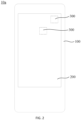
- FIG. 1 is a schematic structural diagram of an electronic device shown in an embodiment.
- FIG. 2 is a schematic structural diagram of a housing assembly shown in FIG. 1 .
- FIG. 3 is a schematic structural diagram of a loop heat pipe shown in FIG. 2 .
- FIG. 4 is an exploded schematic diagram of the structure of the loop heat pipe shown in FIG. 3 .
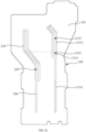
- FIG. 5 is a schematic diagram of the internal structure of the loop heat pipe shown in FIG. 3 (with a second housing removed).
- FIG. 6 is an enlarged schematic diagram of partial structure of the second housing shown in FIG. 4 .
- FIG. 7 is a schematic cross-sectional view of the loop heat pipe shown in FIG. 3 in a first cutting direction.
- FIG. 8 is an enlarged schematic diagram of area A shown in FIG. 7 .
- FIG. 9 is an enlarged schematic diagram of area B shown in FIG. 7 .
- an electronic device 10 of the present disclosure may be a mobile phone, a tablet computer, an e-reader, a notebook computer, a vehicle-mounted device, etc., which includes heat sources 300 and a loop heat pipe 200.
- the loop heat pipe 200 includes a housing component 210, a first capillary structure 220 and a second capillary structure 230.
- the housing component 210 is provided with a pipeline unit 211, a first partition part 213 and at least two evaporation cavities 212.
- the pipeline unit 211 is provided with a liquid replenishment passage 201, the at least two evaporation cavities 212 are spaced apart along a length direction of the liquid replenishment passage 201, and two adjacent evaporation cavities 212 are separated by the first partition part 213.
- At least one of the evaporation cavities 212 includes a vapor outlet 202 communicated with one end of the pipeline unit 211 and a liquid replenishment port 203 communicated with the liquid replenishment passage 201. At least part of the first capillary structure 220 is disposed in the liquid replenishment passage 201 and the at least two evaporation cavities 212.
- the second capillary structure 230 is disposed in at least one of the liquid replenishment passage 201 and the evaporation cavities 212.
- the second capillary structure 230 includes first bodies 231 that correspond to the evaporation cavities 212 on a one-to-one basis. At least one of the first bodies 231 blocks the liquid replenishment port 203 of the corresponding evaporation cavity 212, and at least part of the at least one of the first bodies 231 is in contact with the first capillary structure 220.
- the heat source 300 includes at least two heat sources, and the at least two heat sources correspond to the evaporation cavities 212 on a one-to-one basis.
- the heat sources 300 cooperates with the housing component 210 in thermal conduction, and at least part of the heat sources 300 overlaps the evaporation cavities 212 on a orthogonal projection surface in a thickness direction of the loop heat pipe 200.
- the loop heat pipe 200 has at least two evaporation cavities 212 and can dissipate heat from the at least two heat sources 300. Two adjacent evaporation cavities 212 are separated by the first partition part 213 so that the heat between the adjacent evaporation cavities 212 does not interfere with each other.
- the liquid replenishment port 203 of the evaporation cavity 212 is communicated with one end of the liquid replenishment passage 201, the vapor outlet 202 of the evaporation cavity 212 are communicated with one end of the pipeline unit, and the other end of the pipeline unit 211 is communicated with the liquid replenishment passage 201.
- an anti-backflow structure can be formed.
- the heat generated by operation of the heat sources 300 will be transferred to the corresponding evaporation cavities 212 through the housing component 210.
- the liquid contained in the evaporation cavities 212 is heated and evaporates into vapor. It is difficult for the vapor to flow out from the liquid replenishment port 203 because the liquid replenishment port 203 is blocked, and the vapor will flow out from the vapor outlet 202 to the pipeline unit 211.
- the vapor flows to a cold end of the electronic device 10 through the pipeline unit 211 and is condensed into liquid, and then flows back to the liquid replenishment port 203 through the liquid replenishment passage 201.
- the second capillary structure 230 will absorb the condensed liquid and transport it to the first capillary structure 220 that is in contact with the second capillary structure 230, and replenish the liquid back to the evaporation cavities 212 through the first capillary structure 220 so as to continue evaporation and heat dissipation, implementing cooling of the heat sources 300 so as to prevent local overheating of the electronic device 10 from affecting the performance or causing damage of the electronic device 10, thereby improving the heat dissipation performance of the electronic device 10.
- the second capillary structure 230 absorbs the condensed liquid, and the liquid will fill capillary pores of the second capillary structure 230 so that the second capillary structure 230 can efficiently block the vapor from flowing out from the liquid replenishment ports 203.
- the loop heat pipe 200 can dissipate heat from at least two heat sources 300 respectively, and the anti-backflow structure can be formed through the capillary structures, so that it is difficult for the vapor formed by evaporation to flow out from the liquid replenishment ports 203, thereby realizing gas-liquid separation in the loop heat pipe 200.
- This further makes the loop heat pipe 200 easy to be manufactured and implemented, and can effectively reduce manufacturing costs.
- the electronic device 10 employing the loop heat pipe 200 has good heat dissipation performance, and the loop heat pipe 200 also has low manufacturing cost, which is beneficial to reducing the heat dissipation cost of the electronic device 10.
- At least one of the at least two evaporation cavities 212 corresponding to the at least two heat sources includes the structure as mentioned above. That is, at least one of the evaporation cavities 212 includes the vapor outlet 202 communicated with one end of the pipeline unit 211 and the liquid replenishment port 203 communicated with the liquid replenishment passage 201.
- one or more of the evaporation cavities 212 each includes a vapor outlet 202 communicated with one end of the pipeline unit 211 and a liquid replenishment port 203 communicated with the liquid replenishment passage 201.
- each of the evaporation cavities 212 includes a vapor outlet 202 communicated with one end of the pipeline unit 211 and a liquid replenishment port 203 communicated with the liquid replenishment passage 201.
- the first bodies 231 of the second capillary structure 230 that respectively correspond to the evaporation cavities 212
- at least one of the first bodies 231 blocks the liquid replenishment port 203 of the corresponding evaporation cavity 212, and at least part of the at least one first body 231 is in contact with the first capillary structure 220.
- one or more of the first bodies 231 each blocks the liquid replenishment port 203 of the corresponding one or more evaporation cavities 212, and at least part of each of the one or more first bodies 231 is in contact with the first capillary structure 220.
- each of the first bodies 231 blocks the liquid replenishment port 203 of the corresponding evaporation cavity 212, and at least part of each of the first bodies 231 is in contact with the first capillary structure 220. Accordingly, each of the liquid replenishment port(s) 203 can be blocked by a corresponding first body.
- the second capillary structure 230 is disposed in at least one of the liquid replenishment passage 201 and the evaporation cavities 212" includes that the second capillary structure 230 is disposed in the liquid replenishment passage 201, the second capillary structure 230 is disposed in the evaporation cavities 212, and the second capillary structure 230 is disposed between the liquid replenishment passage 201 and the evaporation cavities 212, as long as the second capillary structure 230 can block the liquid replenishment ports 203 without affecting the transport function of the pipeline unit 211 and the evaporation function of the evaporation cavities 212.
- the second capillary structure 230 blocking the liquid replenishment ports 203 can be understood as that the second capillary structure 230 can block the vapor in the evaporation cavities 212 from flowing to the liquid replenishment ports 203 side, but will not affect flowing of the liquid at the liquid replenishment ports 203 to the evaporation cavities 212.
- the second capillary structure 230 is provided between the evaporation cavities 212 and the liquid replenishment ports 203.
- the second capillary structure 230 can be stacked on the first capillary structure 220 or arranged side by side with the first capillary structure 220.
- a sum of sizes of the first capillary structure 220 and the second capillary structure 230 in the thickness direction is equal to an inner size of the pipeline unit 211 in the thickness direction (as shown in FIG. 9 ).
- the size of the second capillary structure 230 in the thickness direction is equal to the inner size of the pipeline unit 211 in the thickness direction.
- the first capillary structure 220 and the second capillary structure 230 can be capillary structures with the same or different capillary densities.
- the first capillary structure 220 and the second capillary structure 230 can be capillary structures with different thicknesses and the same capillary density.
- the thickness of the first capillary structure 220 is smaller than the thickness of the second capillary structure 230, so that the first capillary structure 220 is used to transport working medium in a liquid state, and the second capillary structure 230 is used to block the working medium in a gas state from flowing to the liquid replenishment ports 203 side.
- the thickness and capillary density of the first capillary structure 220 and the second capillary structure 230 can be adjusted according to actual stacking requirements.
- parameters such as the arrangement manner and thickness of the first capillary structure 220 and the second capillary structure 230 are not specially limited in the embodiments of the present disclosure, and those described above are only examples and not limitation.
- first capillary structure 220 and the second capillary structure 230 can be implemented in a variety of forms, such as a grooved capillary structure, a mesh (woven) capillary structure, a fiber capillary structure, a sintered capillary structure, etc.
- the electronic device 10 further includes a housing 100, and the loop heat pipe 200 is provided in the housing 100.
- the loop heat pipe 200 is integrated onto the housing 100 to facilitate dissipation of the heat from the heat sources 300 installed in the housing 100 through the use of the evaporation cavities 212 and transfer the heat to the cooling part through the use of the pipeline unit 211, thereby making full use of the space of the housing 100 for heat dissipation, improving the heat dissipation performance of the housing 100 and improving the heat dissipation efficiency of the components integrated onto the housing 100, especially the heat sources 300 that easily generate heat (such as a processor, CPU, etc.).
- the housing 100 can be a middle frame, a battery cover, a back cover, or the like. It can be understood that integrating the loop heat pipe 200 with the housing 100 includes, for example, embedding the loop heat pipe 200 in the middle frame to form an integrated middle frame component, or integrating the loop heat pipe 200 and the battery cover into an integrated housing component 10a. That is to say, the type of the housing 100 is not particularly limited in the embodiments of the present disclosure.
- the housing 100 and the loop heat pipe 200 are assembled in modules to form the housing component 10a.
- the housing component 10a has good heat dissipation performance, and it facilitates improving the assembly efficiency of the electronic device 10.
- the heat source 300 may be a control motherboard equipped with a processor, a screen module, a camera module, etc.
- the housing 100 is provided with a heat conduction area (not shown) for the heat source 300 which is disposed opposite to the evaporation cavity 212 along the thickness direction of the housing 100.
- the heat source 300 is in heat conduction fit with the evaporation cavity 212 through the heat conduction area for the heat source 300. Accordingly, it can not only increase the heat dissipation area for the heat source 300 through the housing 100, but also improve the heat dissipation efficiency by using the loop heat pipe 200, which effectively prevents the heat source 300 from overheating.
- the housing 100 may be a bearing structure of the electronic device 10.
- at least some of the components of the electronic device 10 may be directly or indirectly disposed on the housing 100 to be assembled into the electronic device 10.
- the control motherboard is installed on the housing 100 so that the processor and the evaporation cavities 212 are oppositely disposed along the thickness direction of the housing 100.
- the housing 100 may be disposed inside the electronic device 10, and an edge of the housing 100 may be designed as part of a casing of the electronic device 10.
- an edge of the housing 100 is used as the casing of the electronic device 10, it can function to protect the electronic device 10.
- the housing 100 may have a planar or planar-like structure. Therefore, two sides of the housing 100 may be visually distinguished, and the two sides may be referred to as a front side and a back side of the housing 100, or the two sides may be referred to as one side and the other side of the housing 100.
- the interior of the housing 100 may be partially hollowed out as needed to accommodate other components in the electronic device 10.
- part or all of the housing 100 may be made of a metal or alloy material (for example, aluminum alloy).
- the housing 100 can also be made of other materials, which is not specifically limited in the embodiments of the present disclosure.
- the material of the housing 100 is aluminum alloy or steel. Therefore, the housing 100 has good thermal conductivity, which facilitates transferring the heat from the heat sources 300 to the loop heat pipe 200.
- the loop heat pipe 200 can also be disposed on other parts of the electronic device 10.
- the loop heat pipe 200 is disposed between the screen and the middle frame.
- the loop heat pipe 200 is disposed on the side of the battery cover (also called a back cover).
- the loop heat pipe 200 is stacked on other bearing members, heat dissipation components or heat sources 300 along the thickness direction of the electronic device 10 to directly or indirectly improve the heat dissipation efficiency of the heat sources 300 and avoid local overheating of the electronic device 10.
- the heat sources 300 refer to devices in the electronic device 10 that radiate relatively more heat.
- the heat radiated by a device is usually positively correlated with the power consumption of the device.
- the greater the power consumption of the device the greater the heat radiated by the device.
- the heat sources 300 in the present disclosure may be devices in the electronic device 10 the power consumption of which exceeds M% of the power consumption of the entire electronic device, where M may be 30, 40, etc.
- the heat sources 300 may include a central processor, a processing device integrating processing and storage functions, a power supply component such as a battery, and the like.
- the heat sources 300 can also be other devices, such as an image sensor, etc., which are not specifically limited in the embodiments of the present disclosure.
- the "cold end of the electronic device 10" generally refers to a position where the temperature rises slower than the heat sources 300, that is, the position where the internal temperature of the electronic device 10 is lower than the temperature of the "heat sources 300" during the use of the electronic device 10.
- the loop heat pipe 200 also includes working medium (not shown) disposed in the pipeline unit 211 and the evaporation cavities 212, and the second capillary structure 230 blocks the liquid replenishment ports 203 to cause the working medium to move in a direction toward the vapor outlets 202.
- the working fluid in the liquid state can be evaporated into a vapor state.
- the working fluid in the vapor state can flow into the pipeline unit 211 through the vapor outlets 202, and can be re-liquefied in the pipeline unit 211 and then transported to the liquid replenishment ports 203 through the capillary structure.
- the heat generated by the operation of the heat sources 300 will be transferred to the evaporation cavities 212 through the housing component 210. Then, the working medium contained in the evaporation cavities 212 is heated and evaporates into vapor. It is difficult for the vapor to flow out from the liquid replenishment ports 203, and the vapor flows out from the vapor outlets 202 to the pipeline unit 211. The vapor flows to the cold end of the electronic device 10 through the pipeline unit 211 and is condensed back into the liquid working medium, and flows back to the liquid replenishment ports 203 through the liquid replenishment passage 201.
- the second capillary structure 230 will adsorb the condensed working medium and transport it to the first capillary structure 220 that is in contact with the second capillary structure 230, and replenish the working medium back to the evaporation cavities 212 through the first capillary structure 220 to continue evaporation and heat dissipation, achieving cooling of the heat sources 300 to prevent local overheating of the electronic device 10 from affecting the performance or causing damage of the electronic device 10, and to improve the heat dissipation performance of the electronic device 10 .
- working medium includes but is not limited to coolant and other fluids that can be applied to the loop heat pipe 200, and the boiling point of the “working medium” can be adjusted according to actual needs and is not limited here.
- the first capillary structure 220 is disposed in the evaporation cavities 212 to form an evaporator.
- At least part of the second capillary structure 230 is stacked on the first capillary structure 220 to block the liquid replenishment ports 203.
- the contact area between the second capillary structure 230 and the first capillary structure 220 can be increased, and the liquid stored in the second capillary structure 230 can be transported to the first capillary structure 220 more efficiently, which facilitates replenishing the liquid back to the evaporation cavities 212 through the first capillary structure 220.
- the second capillary structure 230 is filled in the pipeline unit 211 to block the liquid replenishment ports 203.
- the second capillary structure 230 can be directly filled in the pipeline unit 211 to block the liquid replenishment ports 203, making the arrangement of the first capillary structure 220 and the second capillary structure 230 more flexible.
- the thickness of the first capillary structure 220 is H1, 0.02mm ⁇ H1 ⁇ 0.1mm. As such, the thickness of the first capillary structure 220 can be flexibly set so that the evaporation cavities 212 have enough evaporation space to facilitate rapid evaporation of the liquid stored in the first capillary structure 220 into vapor.
- 0.04mm ⁇ H1 ⁇ 0.08mm 0.04mm ⁇ H1 ⁇ 0.08mm.
- H1 0.02mm, 0.03mm, 0.04mm, 0.05mm, 0.06mm, 0.07mm, 0.08mm, 0.09mm, or 0.1mm.
- the second capillary structure 230 includes at least one layer of capillary structure. In this way, the second capillary structure 230 can be formed by one layer of capillary structure, or can be formed by superimposing multiple layers of capillary structures.
- a capillary structure is cut into a set shape, and multiple layers of such capillary structure are superposed to form the second capillary structure 230.
- the capillary structure can also be cut into the first capillary structure 220. In this way, one kind of capillary structure can be used to form the first capillary structure 220 and the second capillary structure 230, which is beneficial to cost saving.
- the thickness of the second capillary structure 230 is H2, and 0.1mm ⁇ H2 ⁇ 0.3mm. As such, the thickness of the second capillary structure 230 can be reasonably set according to the size of the liquid replenishment ports 203, which can block the liquid replenishment ports 203 without affecting the backflow of the liquid.
- 0.15mm ⁇ H2 ⁇ 0.25mm 0.15mm ⁇ H2 ⁇ 0.25mm.
- H1 0.1mm, 0.12mm, 0.15mm, 0.18mm, 0.2mm, 0.21mm, 0.23mm, 0.25mm, 0.27mm, or 0.3mm. It should be noted that H1 can be any value within a range of 0.02mm ⁇ 0.1mm, and those listed above are merely examples and not limitation.
- the maximum thickness of the loop heat pipe 200 is 0.2 mm to 0.5 mm.
- the loop heat pipe 200 is made as light and thin as possible to meet the thin and light design requirements of the electronic device 10.
- H2 can be any value within the range of 0.1mm ⁇ 0.3mm, and those listed above are only examples and not limitation.
- the second capillary structure 230 includes at least one layer of capillary structure. In this way, the second capillary structure 230 can be formed by one layer of capillary structure, or can be formed by superimposing multiple layers of capillary structures.
- a capillary structure is cut into a set shape, and multiple layers of such capillary structure are superposed to form the second capillary structure 230.
- the capillary structure can also be cut into the first capillary structure 220. In this way, one kind of capillary structure can be used to form the first capillary structure 220 and the second capillary structure 230, which is beneficial to cost saving.
- the maximum thickness of the loop heat pipe 200 is 0.2mm, 0.22mm, 0.25mm, 0.28mm, 0.3mm, 0.31mm, 0.33mm, 0.35mm, 0.37mm, 0.4mm, 0.41mm, 0.43mm, 0.45mm, 0.47mm, or 0.5mm. It should be noted that the maximum thickness of the loop heat pipe 200 can be any value within the range of 0.2 mm to 0.5 mm, and those listed above are only examples and not limitation.
- first partition part 213 can be implemented in a variety of forms, including at least one of a partition plate, an isolation strip, an isolation hole, etc.
- the first partition part 213 includes a first partition plate 2131, and the first partition plate 2131 is disposed between two adjacent evaporation cavities 212. In this way, two adjacent evaporation cavities 212 are separated by the partition plate to reduce mutual interference, which is easy to be implemented.
- the first partition part 213 includes a first isolation hole 2132, and the first isolation hole 2132 is used to separate two adjacent evaporation cavities 212.
- the isolation hole can be used to separate two adjacent evaporation cavities 212 to reduce mutual interference.
- two adjacent evaporation cavities 212 are spaced apart through the isolation hole, thereby reducing direct heat transfer through the housing component 210 and further reducing mutual interference.
- the first partition part 213 includes a first partition plate 2131 and a first isolation hole 2132.
- the first isolation hole 2132 cooperates with the first partition plate 2131 to separate two adjacent evaporation cavities 212.
- the second capillary structure 230 can be implemented in various forms.
- it includes at least two first bodies 231 that are provided separately and are used to block the liquid replenishment ports 203 of the corresponding evaporation cavities 212.
- the second capillary structure 230 includes a second body 232 disposed in the liquid replenishment passage 201.
- the first bodies 231 are in contact with the first capillary structure 220 and connected to the second body 232 to block the liquid replenishment ports 203.
- the liquid can be quickly transported to the evaporation cavities 212, and by disposing the second body 232 in the liquid replenishment passage 201, the liquid suction speed can be increased, thereby further increasing the liquid replenishing speed of the evaporation cavities 212.
- connecting the second body 232 to the at least two first bodies 231 is beneficial to increasing the blocking thickness, improving the effect of blocking the vapor, and further improving the anti-backflow performance of the loop heat pipe 200.
- the pipeline unit 211 also includes a vapor passage 204 and a flow return passage 205.
- One end of the vapor passage 204 is communicated with the vapor outlets of the at least two evaporation cavities 212, the other end of the vapor passage 204 is communicated with one end of the flow return passage 205, and the other end of the flow return passage 205 is communicated with the liquid replenishment passage 201.
- At least part of the second capillary structure 230 is provided in the liquid replenishment passage 201 and the flow return passage 205.
- the vapor flowing out of the evaporation cavities 212 is transported through the vapor passage 204, the condensed vapor is transported to the liquid replenishment passage 201 through the flow return passage 205, and then the liquid is transported to the evaporation cavities 212 through the liquid replenishment passage 201, which facilitates realization of gas-liquid recycling, and improves the heat dissipation performance of the loop heat pipe 200. That is, multiple circulation passages are formed through the vapor passage 204, the flow return passage 205, the liquid replenishment passage 201 and the at least two evaporation cavities 212.
- the passage formed by the communication between the pipeline unit 211 and the evaporation cavities 212 can be understood as a circulation passage through which the working medium circulates, and the shape of the circulation passage is not necessarily a single ring.
- at least two vapor passages 204 share part of the flow return passage 205, and are communicated with the evaporation cavities 212 through the liquid replenishment passage 201 to form circulation passages.
- at least two flow return passages 205 share part of the vapor passage 204 and are communicated with the evaporation cavities 212 through the liquid replenishment passage 201 to form circulation passages.
- At least two flow return passages 205 are communicated with at least two vapor passages 204 respectively, and the at least two flow return passages 205 share the liquid replenishment passage 201 and are communicated with the evaporation cavities 212 to form circulation passages.
- the second capillary structure 230 is provided in the liquid replenishment passage 201 and the flow return passage 205, which facilitates quickly absorbing of the liquid in the liquid replenishment passage 201 and the flow return passage 205 by the second capillary structure 230, and transporting the liquid to the first capillary structure 220 through the second capillary structure 230 and finally to the evaporation cavities 212 through the first capillary structure 220, so as to implement rapid liquid replenishment of the evaporation cavities 212.
- the vapor passage 204 includes a second partition part 214 and first flow passages 204a that are communicated with the evaporation cavities 212 in a one-to-one correspondence, and two adjacent first flow passages 204a are separated by the second partition part 214.
- mutual interference between the evaporation cavities 212 can be further avoided, thereby avoiding mutual interference between the heat sources 300 and ensuring the heat dissipation efficiency of the respective heat sources 300.
- the second partition part 214 can be implemented in a variety of ways, including at least one of a partition plate, an isolation strip, an isolation hole, etc.
- the second partition part 214 includes a second partition plate 2141, and the second partition plate 2141 is disposed between two adjacent evaporation cavities 212. In this way, the two adjacent first flow passages 204a are separated by the partition plate to reduce mutual interference, which is easy to be implemented.
- the second partition part 214 includes a second isolation hole 2142, which is used to separate two adjacent first flow passages 204a.
- the second isolation hole 2142 can be used to separate two adjacent first flow passages 204a to reduce mutual interference.
- the two adjacent first flow passages 204a are spaced apart through the isolation hole, thereby reducing the direct transfer of heat through the housing component 210 and further reducing mutual interference.
- the second partition part 214 includes a second partition plate 2141 and a second isolation hole 2142.
- the second isolation hole 2142 cooperates with the second partition plate 2141 to separate two adjacent first flow passages 204a.
- first partition part 213 and the second partition part 214 are integrally formed.
- the first capillary structure 220 includes a third body 221 disposed in the liquid replenishment passage 201 and the at least two evaporation cavities 212, a fourth body 222 disposed in the vapor passage 204 and a fifth body 223 disposed in the flow return passage 205.
- One end of the fourth body 222 is connected to the third body 221 through the vapor outlet 202, the other end of the fourth body 222 is connected to one end of the fifth body 223, and the other end of the fifth body 223 is connected to the third body 221 through the liquid replenishment passage 201.
- the first capillary structure 220 is disposed in the pipeline unit 211 and the evaporation cavities 212, which facilitates adsorption of condensed liquid and facilitates re-transporting of the condensed liquid to the evaporation cavities 212 along the first capillary structure 220 so as to continuously provide liquid to the evaporation cavities 212.
- the third body 221 covers the bottoms of the evaporation cavities 212 and the liquid replenishment passage 201
- the fourth body 222 covers the bottom of the vapor passage 204
- the fifth body 223 is disposed at the bottom of the flow return passage 205, so that the condensed liquid can be efficiently absorbed.
- housing component 210 can be implemented in a variety of ways, as long as the pipeline unit 211 and the evaporation cavities 212 can be formed.
- the housing component 210 includes a first housing 215, a second housing 216 and a third partition part 217.
- the first housing 215 cooperates with the second housing 216 to form an accommodation cavity
- the third partition part 217 and the first partition part 213 are disposed and spaced apart in the accommodation cavity to separate the accommodation cavity into the vapor passage 204, the flow return passage 205, the liquid replenishment passage 201 and the evaporation cavities 212.
- first housing 215 and the second housing 216 can be manufactured in a variety of ways, including but not limited to stamping, etching, laser engraving, turning and milling, and other methods.
- the first housing 215 and the second housing 216 are stamped separately and then assembled together.
- the second capillary structure 230 is provided with an avoidance groove 233 to avoid the third partition part 217.
- the avoidance groove 233 the second capillary structure 230 will not interfere with the third partition part 217 and can efficiently block the liquid replenishment ports 203 so that the vapor evaporated from the evaporation cavities 212 will not flow from the liquid replenishment ports 203 into the liquid replenishment passage 201.
- the third partition part 217 includes a third partition plate 208, and two ends of the third partition plate 208 abut against the first housing 215 and the second housing 216, respectively, to separate part of the vapor passage 204 and part of the evaporation cavities 212 from the flow return passage 205.
- the third partition plate 208 separates the part of the vapor passages 204 and the part of the evaporation cavities 212 from the flow return passage 205, thereby reducing gas-liquid mixing that affects the heat dissipation efficiency of the loop heat pipe 200.
- the first partition part 213 includes a first partition plate 2131, two ends of the first partition plate 2131 respectively abut against the first housing 215 and the second housing 216 to separate two adjacent evaporation cavities 212.
- the vapor passage 204 includes a second partition part 214 and first flow passages 204a each of which is communicated with a respective evaporation cavity 212.
- the second partition part 214 includes a second partition plate 2141, and two ends of the second partition plate 2141 respectively abut against the first housing 215 and the second housing 216 to separate two adjacent first flow passages 204a.
- first partition plate 2131, the second partition plate 2141 and the third partition plate 208 are integrally formed with one of the first housing 215 and the second housing 216, which is beneficial to reducing the assembly process and improving the assembly efficiency of the loop heat pipe 200.
- the third partition part 217 includes a third isolation hole 209 penetrating the first housing 215 and the second housing 216 to separate part of the vapor passage 204 and part of the evaporation cavities 212 from the flow return passage 205.
- the third isolation hole 209 can be used to isolate the part of the vapor passage 204 and the part of the evaporation cavities 212 from the flow return passage 205, thereby reducing the gas-liquid mixing that affects the heat dissipation efficiency of the loop heat pipe 200.
- the third isolation hole 209 allows the part of the vapor passage 204 and the part of the evaporation cavities 212 to be spaced apart from the flow return passage 205, thereby reducing the direct transferring of the heat in the vapor passage 204 and the evaporation cavity 212 to the flow return passage 205 through the housing component 210 which will cause the liquid in the flow return passage 205 to be heated and evaporate, resulting in the gas-liquid mixing phenomenon that affects the heat dissipation efficiency of the loop heat pipe 200.
- the housing component 210 includes a first welding layer 2133 that is welded and fixed to the first housing 215 and the second housing 216, and the first isolation hole 2132 is opened in the first welding layer 2133.
- part of the first housing 215 is weld together with the second housing 216 through the first welding layer 2133, thereby achieving separation between two adjacent evaporation cavities 212.
- the two adjacent evaporation cavities 212 are spaced apart to reduce direct transfer of the heat through the housing component 210 and further reduce mutual interference.
- the vapor passage 204 includes a second partition part 214 and first flow passages 204a each of which is communicated with a respective evaporation cavity 212.
- the second partition part 214 includes a second isolation hole 2142 for separating two adjacent first flow passages 204a;
- the housing component 210 includes a second welding layer 2143 that is welded and fixed to the first housing 215 and the second housing 216, and the second isolation hole 2142 is opened in the second welding layer 2143.
- the part of the first housing 215 is weld together with the second housing 216 through the second welding layer 2143 to separate the two adjacent first flow passages 204a.
- the two adjacent first flow passages 204a are spaced apart to reduce the direct transfer of the heat through the housing component 210 and further reduce mutual interference.
- the housing component 210 includes a third welding layer 218 that is welded and fixed to the first housing 215 and the second housing 216, and the third isolation hole 209 is opened in the third welding layer 218. In this way, part of the first housing 215 is welded together with the second housing 216 through the third welding layer 218 to separate part of the vapor passage 204 and part of the evaporation cavities 212 from the flow return passage 205.
- the part of the vapor passage 204 and the part of the evaporation cavities 212 are spaced apart from the flow return passage 205, thereby reducing the direct transfer of the heat in the vapor passage 204 and the evaporation cavity 212 to the flow return passage 205 through the housing component 210 which will cause the liquid in the flow return passage 205 to be heated and evaporate, resulting in the gas-liquid mixing phenomenon which affects the heat dissipation efficiency of the loop heat pipe 200.
- At least one of the first housing 215 and the second housing 216 is provided with a groove 206, and the other of the first housing 215 and the second housing 216 covers the groove 206 to form an accommodation cavity. In this way, by using the groove 206, it facilitate the formation of the accommodation cavity.
- the first housing 215 is provided with a groove 206
- the second housing 216 is used as a cover. That is, the second housing 216 covers the side of the first housing 215 at the opening of the groove 206, and the groove 206 on the first housing 215 together with the second housing 216 enclose and form the closed pipeline unit 211 and evaporation cavities 212.
- the second housing 216 is provided with a groove 206, and the first housing 215 is used as a cover. That is, the first housing 215 covers the side of the second housing 216 at the opening of the groove 206, and the groove 206 of the second housing 216 together with the first housing 215 enclose and form the closed pipeline unit 211 and evaporation cavities 212.
- each of the first housing 215 and the second housing 216 is provided with a groove 206. That is, the opening of the groove 206 on the first housing 215 and the opening of the groove 206 on the second housing 216 are arranged oppositely, and the grooves 206 of the second housing 216 and the first housing 215 together enclose and form the closed pipeline unit 211 and evaporation cavities 212.
- the first housing 215 is provided with a groove 206
- the first capillary structure 220 covers the bottom of the groove 206
- the first capillary structure 220 is provided with a first avoidance hole 224 to avoid the first partition part 213 and a third avoidance hole to avoid the third partition part 217.
- the first capillary structure 220 covers the bottom of the groove 206, and the partition parts are avoided through the avoidance holes, so that the first capillary structure 220 is integrated onto the first housing 215, covers the second capillary structure 230, and then is assembled with the second housing 216, and thus the loop heat pipe 200 can be manufactured, resulting in high assembly efficiency of the loop heat pipe 200.
- the first capillary structure 220 is also provided with a second avoidance hole 225 to avoid the second partition part 214.
- the second housing 216 is provided with a support column 207, the support column 207 avoids the second capillary structure 230 and protrudes in a direction toward the first capillary structure 220.
- the support column 207 abuts against and cooperates with the first capillary structure 220. In this way, by disposing the support column 207, the first housing 215 and the second housing 216 will not be easily deformed to cause the pipeline unit 211 or the evaporation cavities 212 to be squashed and broken, which is beneficial to improving the reliability of the loop heat pipe 200.
- the support column 207 when the second housing 216 is in a non-compressed state, the support column 207 has a clearance fit with the first capillary structure 220; and when the second housing 216 and/or the first housing 215 is in a compressed state, the support column 207 is in contact fit with the first capillary structure 220 to support the first housing 215 and the second housing 216. In this way, since there is a gap between the first capillary structure 220 and the support part, the support part will not block the vaporized cooling medium in the first capillary structure 220, so that the flow efficiency of the cooling medium can be improved.
- the support part contacts the first capillary structure 220 to support the body, and thus the first capillary structure 220 can be used to buffer the force on the body, which can suppress or avoid deformation of the body, and prevent that some areas of the body cannot be effectively supported due to the deviation, which in turn causes deformation of the areas, affecting the heat dissipation effect.
- one of the first housing 215 and the second housing 216 includes the housing 100 or a battery cover.
- one of the first housing 215 and the second housing 216 is integrally formed with the housing 100 or the battery cover, which facilitates the full use of the thickness space of the housing 100 or the battery cover to integrate the loop heat pipe 200, which is beneficial to make the electronic device 10 thinner and lighter.
- the first capillary structure 220 is disposed in the evaporation cavities 212, the liquid replenishment passage 201, the vapor passage 204 and the flow return passage 205, and is spaced apart from an inner side wall of the housing component 210. In this way, the arrangement of the first capillary structure 220 will not cause pipe plugging of the loop heat pipe 200.
- the housing 100 is provided with a receiving hole 110, and at least part of the loop heat pipe 200 is disposed in the receiving hole 110, so that at least part of the loop heat pipe 200 is embedded in the housing 100.
- the thickness space of the housing 100 can be fully utilized to integrate the loop heat pipe 200, that is, the protruding thickness of the heat dissipation structure can be actively reduced, which is beneficial to making the electronic device 10 thinner and lighter.
- the housing component 210 is provided with a skirt 219
- the housing 100 is provided with a bearing body 120 disposed on a side wall of the receiving hole 110
- the skirt 219 is fixedly connected to the bearing body 120.
- the “bearing body 120” can be “a part of the housing 100", that is, the “bearing body 120" and “other parts of the housing 100, such as the body of the housing 100" are integrally formed and manufactured; or the “bearing body 120" can be an independent member separated from “other parts of the housing 100, such as the body of the housing 100", that is, the “bearing body 120" can be manufactured independently, and then combined with “other parts of the housing 100, such as the body of the housing 100" to form an integrated whole.
- a body and “a part” can be part of a corresponding "member”, that is, “a body” or “a part” is integrally formed and manufactured with “other parts of the member”; or can be an independent member separated from “other parts of the member”, that is, “a body” or “a part” can be manufactured independently, and then combined with “other parts of the member” to form an integrated whole.
- the expressions “a body” and “a part” mentioned above in the present disclosure are only examples for the convenience of reading, and are not intended to limit the protection scope of the present disclosure. Those including the above features and having the same functions should be understood as being equivalent to the technical solution of the present disclosure.
- the "second housing 216" can be one of parts of the module “housing component 210", that is, it is assembled into a module with “other members of the housing component 210" and then assembled in a modular manner; or can be relatively independent from “other members of the housing component 210" and can be installed separately, that is, it can be integrated with “other members of the housing component 210" in the device to form an integrated whole.
- the members included in a "unit”, “component” and “terminal” of the present disclosure can also be flexibly combined, that is, modular production can be carried out according to actual conditions, and modular assembly can be carried out as an independent module; they can also be assembled separately and form a module in the device.
- modular production can be carried out according to actual conditions, and modular assembly can be carried out as an independent module; they can also be assembled separately and form a module in the device.
- the division of the above member in the present disclosure is only one of the embodiments for the convenience of reading, and is not intended to limit the protection scope of the present disclosure.
- the electronic device 10 may also include one or more of the following components: a processing component 11, a memory 12, a power supply component 13, a multimedia component 14, an audio component 15, an input/output interface 16, a sensor component 17, and a communication component 18.
- the processing component 11 generally controls the overall operations of the electronic device 10, such as operations associated with display, telephone calls, data communications, camera operations, and recording operations.
- the processing component 11 may include one or more processors to execute instructions so as to implement all or part of the steps of the foregoing methods.
- the processing component 11 may include one or more modules to facilitate the interaction between the processing component and other components.
- the processing component 11 may include a multi-media module to facilitate the interaction between the multi-media component and the processing component.
- the memory 12 is configured to store various types of data to support operations on the electronic device. Examples of the data include instructions for any application or method operating on the electronic device, contact data, phone book data, messages, pictures, videos, etc.
- the memory 12 can be implemented in any type of volatile or non-volatile storage device, such as a static random access memory (SRAM), an electrically erasable programmable read-only memory (EEPROM), an erasable Programmable read-only memory (EPROM), a programmable read-only memory (PROM), a read-only memory (ROM), a magnetic memory, a flash memory, a magnetic disk and an optical disk, or a combination thereof.
- SRAM static random access memory
- EEPROM electrically erasable programmable read-only memory
- EPROM erasable Programmable read-only memory
- PROM programmable read-only memory
- ROM read-only memory
- magnetic memory a magnetic memory
- flash memory a flash memory
- magnetic disk and an optical disk or a combination thereof.
- the control motherboard includes the processing component and the memory.
- the power supply component 13 provides power to various components of the electronic device.
- the power supply component 13 may include a power management system, one or more power supplies, and other components associated with generating, managing, and distributing power for the electronic device.
- the multimedia component 14 includes the display module of the present disclosure to facilitate human-computer interaction. If the display module includes a touch panel, the display module may be implemented as a touch screen to receive input signals from the user.
- the touch panel includes one or more touch sensors to sense touches, swipes, and gestures on the touch panel. The touch sensor can not only sense a boundary of a touch or swipe action, but also detect the time duration and pressure associated with the touch or swipe operation.
- the multimedia component 14 includes a front camera and/or a rear camera. When the electronic device is in an operating mode, such as a shooting mode or a video mode, the front camera and/or the rear camera can receive external multimedia data. Each of the front camera and the rear camera can be a fixed optical lens system or have a focal length and optical zoom capabilities.
- the audio component 15 is configured to output and/or input audio signals.
- the audio component includes a microphone (MIC).
- the microphone When the electronic device is in an operation mode, such as a call mode, a recording mode or a voice recognition mode, the microphone is configured to receive external audio signals.
- the received audio signals may be further stored in the memory or sent via the communication component.
- the audio component 15 further includes a speaker configured to output the audio signals.
- the input/output interface 16 provides an interface between the processing component and a peripheral interface module.
- the peripheral interface module may be a keyboard, a click wheel, a button, or the like.
- the button may include but is not limited to a home button, a volume button, a start button, and a lock button.
- the sensor component 17 includes one or more sensors configured to provide various state evaluations of the electronic device.
- the sensor component 17 can detect an on/off state of the electronic device and relative positioning of a component such as a display or a keypad of the electronic device.
- the sensor component 17 can also detect a position change of the electronic device or a component of the electronic device, presence or absence of contact with the electronic device by the user, orientation or acceleration/deceleration of the electronic device, and temperature changes of the electronic device.
- the sensor component 17 may include a proximity sensor configured to detect presence of a nearby object without any physical contact.
- the sensor component may also include a photosensitive element, such as a CMOS or CCD image sensor, configured to be used in imaging applications.
- the sensor component 17 may also include an acceleration sensor, a gyroscope sensor, a magnetic sensor, a pressure sensor or a temperature sensor.
- the communication component 18 is configured to facilitate wired or wireless communication between the electronic device and other devices.
- the electronic device can access a wireless network based on a communication standard, such as Wi-Fi, 2G, 3G, 4G, 5G or 6G, or a combination thereof.
- the communication component 18 receives a broadcast signal or broadcast related information from an external broadcast management system via a broadcast channel.
- the communication component 18 further includes a near field communication (NFC) module to facilitate short-range communication.
- the NFC module can be implemented based on a radio frequency identification (RFID) technology, an infrared data association (IrDA) technology, an ultra-wideband (UWB) technology, a Bluetooth (BT) technology or other technologies.
- RFID radio frequency identification
- IrDA infrared data association
- UWB ultra-wideband
- BT Bluetooth
- first, second, etc. are used for descriptive purposes only and cannot be understood as indicating or implying relative importance or implicitly indicating the quantity of indicated technical features. Thus, the features defined by “first,” “second,” etc. may explicitly or implicitly include at least one of these features. In the description of the present disclosure, "a plurality” means at least two, such as two, three, etc., unless otherwise expressly and specifically limited.
- the terms “install”, “communicate”, “connect”, “fix” and so on should be understood in a broad sense.
- it can be a fixed connection or a detachable connection, or be integrated; it can be a mechanical connection or an electrical connection; it can be a direct connection or an indirect connection through an intermediate medium; it can be an internal communication between two elements or an interactive relationship between two elements, unless otherwise clearly indicated.
- install can be a fixed connection or a detachable connection, or be integrated; it can be a mechanical connection or an electrical connection; it can be a direct connection or an indirect connection through an intermediate medium; it can be an internal communication between two elements or an interactive relationship between two elements, unless otherwise clearly indicated.
- the specific meanings of the above terms in the present disclosure can be understood according to specific conditions.
- a first feature being “on” or “under” a second feature may mean that the first and second features are in direct contact, or the first and second features may be in indirect contact through an intermediate medium.
- the first feature is "on”, “above” and “on top of' the second feature may mean that the first feature is directly above or obliquely above the second feature, or simply means that the first feature is in a higher level than the second feature.
- the first feature being “below”, “under” and “beneath” the second feature may mean that the first feature is directly below or obliquely below the second feature, or simply means that the first feature has a smaller height than the second feature in level.
Landscapes
- Engineering & Computer Science (AREA)
- Physics & Mathematics (AREA)
- Thermal Sciences (AREA)
- Mechanical Engineering (AREA)
- General Engineering & Computer Science (AREA)
- Life Sciences & Earth Sciences (AREA)
- Sustainable Development (AREA)
- Microelectronics & Electronic Packaging (AREA)
- Cooling Or The Like Of Electrical Apparatus (AREA)
Abstract
Description
- The present disclosure relates to the field of electronic technology, and in particular to a loop heat pipe, a housing assembly and an electronic device.
- Electronic devices such as mobile phones and tablets have become indispensable technological products in people's life, study and entertainment. With the development of the electronic devices, temperature rise experience has gradually become an important factor considered by consumers when purchasing the electronic devices.
- A loop heat pipe is usually used to improve heat dissipation efficiency. The loop heat pipe further improves the heat dissipation efficiency through a gas-liquid separation structure.
- The present disclosure provides a loop heat pipe, a housing assembly, and an electronic device. The loop heat pipe can dissipate heat from at least two heat sources separately, is easy to be manufactured, and can effectively reduce manufacturing cost. The housing assembly and the electronic device, with the use of the loop heat pipe, have good heat dissipation performance, which is beneficial to reducing the heat dissipation cost of the electronic device.
- According to a first aspect, a loop heat pipe is provided, including a housing component, a first capillary structure and a second capillary structure. The housing component is provided with a pipeline unit, a first partition part and at least two evaporation cavities. The pipeline unit is provided with a liquid replenishment passage, the at least two evaporation cavities are spaced apart in a length direction of the liquid replenishment passage, and two adjacent evaporation cavities are separated by the first partition part. At least one of the evaporation cavities includes a vapor outlet communicated with one end of the pipeline unit and a liquid replenishment port communicated with the liquid replenishment passage. At least part of the first capillary structure is disposed in the liquid replenishment passage and at least two evaporation cavities. The second capillary structure is disposed in at least one of the liquid replenishment passage and the evaporation cavities. The second capillary structure includes first bodies that correspond to the evaporation cavities on a one-to-one basis. At least one of the first bodies blocks the liquid replenishment port of the corresponding evaporation cavity, and at least part of the at least one of the first bodies is in contact with the first capillary structure.
- The technical solution provided by the embodiments of the present disclosure can include the following beneficial effects.
- The loop heat pipe has at least two evaporation cavities and can dissipate heat from at least two heat sources. Two adjacent evaporation cavities are separated by the first partition part, so that the heat between the adjacent evaporation cavities does not interfere with each other. At the same time, by disposing the second capillary structure in at least one of the liquid replenishment passage and the evaporation cavities to block the liquid replenishment ports, an anti-backflow structure can be formed. Accordingly, the liquid contained in the evaporation cavities is heated and evaporates into vapor, which flows out from the vapor outlets to the pipeline unit because the liquid replenishment ports are blocked. The vapor flows to a cold end through the pipeline unit and condenses into liquid, and then flows back to the liquid replenishment ports through the liquid replenishment passage. During this process, the second capillary structure will absorb the condensed liquid and transport it to the first capillary structure that is in contact with it, and replenish the liquid back to the evaporation cavities through the first capillary structure, which improves the heat dissipation performance of the loop heat pipe. As such, the loop heat pipe can dissipate heat from at least two heat sources separately, and form the anti-backflow structure through the capillary structures, making it difficult for the vapor formed by evaporation to flow out from the replenishment ports, thereby achieving separation of gas and liquid in the loop heat pipe. Furthermore, it makes the loop heat pipe easy to be manufactured and implemented, which can effectively reduce manufacturing costs.
- Optionally, the first bodies are stacked on the first capillary structure to block the liquid replenishment ports; or
at least part of the first bodies is filled in the liquid replenishment passage to block the liquid replenishment ports. - Optionally, the loop heat pipe further includes a working medium disposed in the pipeline unit and the evaporation cavities, and the first bodies block the liquid replenishment ports to cause the working medium to move toward the vapor outlets.
- Optionally, a thickness of the first capillary structure is H1, 0.02mm≤H1≤0.1mm; and/or
the second capillary structure includes at least one layer of capillary structure, and/or, a thickness of the second capillary structure is H2, 0. 1mm≤H2≤0.3mm. - Optionally, the maximum thickness of the loop heat pipe is 0.2 mm to 0.5 mm.
- Optionally, the first partition part includes a first partition plate, and the first partition plate is disposed between two adjacent evaporation cavities. And/or, the first partition part includes a first isolation hole, and the first isolation hole is configured to separate two adjacent evaporation cavities.
- Optionally, the second capillary structure includes a second body disposed in the liquid replenishment passage. The first bodies are in contact with the first capillary structure and connected with the second body to block the liquid replenishment ports.
- Optionally, the pipeline unit further includes a vapor passage and a flow return passage. One end of the vapor passage is communicated with the vapor outlets of the at least two evaporation cavities, the other end of the vapor passage is communicated with one end of the flow return passage, and the other end of the flow return passage is communicated with the liquid replenishment passage;
at least part of the second capillary structure is disposed in the liquid replenishment passage and the flow return passage. - Optionally, the vapor passage includes a second partition part and first flow passages that are communicated with the evaporation cavities in a one-to-one correspondence, and two adjacent first flow passages are separated by the second partition part.
- Optionally, the second partition part includes a second partition plate, and the second partition plate is disposed between two adjacent evaporation cavities, and/or
the second partition part includes a second isolation hole, and the second isolation hole is configured to separate two adjacent first flow passages. - Optionally, the first capillary structure includes a third body disposed in the liquid replenishment passage and the at least two evaporation cavities, a fourth body disposed in the vapor passage, and a fifth body disposed in the flow return passage. One end of the fourth body is connected to the third body through the vapor outlets, the other end of the fourth body is connected to one end of the fifth body, and the other end of the fifth body is connected to the third body through the liquid replenishment passage.
- Optionally, the housing component includes a first housing, a second housing and a third partition part. The first housing and the second housing cooperate to form an accommodation cavity. The third partition part and the first partition are disposed and spaced part in the accommodation cavity to partition the accommodation cavity into a vapor passage, a flow return passage, a liquid replenishment passage and evaporation cavities.
- Optionally, the first partition part includes a first partition plate, and two ends of the first partition plate respectively abut against the first housing and the second housing to separate two adjacent evaporation cavities; and/or
- the vapor passage includes a second partition part and first flow passages that are communicated with the evaporation cavities in a one-to-one correspondence, the second partition part includes a second partition plate, and two ends of the second partition plate respectively abut against the first housing and the second housing to separate two adjacent first flow passages; and/or
- the third partition part includes a third partition plate, and two ends of the third partition plate respectively abut against the first housing and the second housing to separate part of the vapor passage and part of the evaporation cavities from the flow return passage.
- Optionally, the third partition part includes a third isolation hole, and the third isolation hole is configured to separate part of the vapor passage and part of the evaporation cavities from the flow return passage.
- Optionally, the first partition part includes a first isolation hole, and the first isolation hole is configured to separate two adjacent evaporation cavities; the housing component includes a first welding layer that is welded and fixed to the first housing and the second housing, and the first isolation hole is opened in the first welding layer, and/or
- the vapor passage includes a second partition part and first flow passages that are communicated with the evaporation cavities in a one-to-one correspondence, and the second partition part includes a second isolation hole configured to separate two adjacent first flow passages; the housing component includes a second welding layer that is welded and fixed to the first housing and the second housing, and the second isolation hole is opened in the second welding layer, and/or
- the housing component includes a third welding layer that is welded and fixed to the first housing and the second housing, and the third isolation hole is opened in the third welding layer.
- Optionally, at least one of the first housing and the second housing is provided with a groove, and the other one of the first housing and the second housing covers the groove to form an accommodation cavity.
- Optionally, the first housing is provided with a groove, the first capillary structure covers a bottom of the groove, the first capillary structure is provided with a first avoidance hole for avoiding the first partition part and a third avoidance hole for avoiding the third partition part, and the second capillary structure is provided on the first capillary structure; and/or
the first partition part and the third partition part are stamped and formed with the second housing. - Optionally, the second housing is provided with a support column, the support column avoids the second capillary structure and protrudes in a direction toward the first capillary structure;
- the support column abuts against and fits the first capillary structure;
- or when the second housing is in a non-compressed state, the support column is in clearance fit with the first capillary structure; when the second housing and/or the first housing is in a compressed state, the support column is in contact fit with the first capillary structure to support the first housing and the second housing.
- Optionally, one of the first housing and the second housing includes a housing or a battery cover.
- Optionally, the first capillary structure is disposed in the evaporation cavities, the liquid replenishment passage, the vapor passage and the flow return passage, and is disposed to be spaced apart from an inner side wall of the housing component.
- According to a second aspect, a housing assembly is also provided, including a housing and the loop heat pipe in any of the above embodiments, and the loop heat pipe is provided in the housing.
- The technical solution provided by the embodiments of the present disclosure can include the following beneficial effects.
- The housing assembly integrates the loop heat pipe onto the housing to facilitate to dissipating heat from at least two heat sources installed on the housing by using the evaporation cavities and then transferring the heat to a cooling part using the pipeline unit, thereby making full use of the housing's space for heat dissipation, improving the heat dissipation performance of the housing, facilitating to improving the heat dissipation efficiency of components integrated onto the housing, especially the heat sources that easily generate heat (such as motherboard chips, CPUs, etc.). As such, the housing assembly has good heat dissipation performance.
- Optionally, the housing is provided with a receiving hole, and at least part of the loop heat pipe is disposed in the receiving hole, so that at least part of the loop heat pipe is embedded in the housing. In this way, at least part of the loop heat pipe is embedded in the housing through the receiving hole, and the thickness space of the housing can be fully utilized to integrate the loop heat pipe, that is, a protruding thickness of the heat dissipation structure can be actively reduced, which is conducive to making the electronic device thinner and lighter.
- Optionally, the housing component is provided with a skirt, the housing is provided with a bearing body disposed on a side wall of the receiving hole, and the skirt is fixedly connected to the bearing body.
- According to a third aspect, an electronic device is also provided, including heat sources and the loop heat pipe in any of the above embodiments, or the housing assembly in any of the above embodiments, and the heat sources include at least two heat sources corresponding to the evaporation cavities on a one-to-one basis, the heat sources cooperate with the housing assembly in heat conduction, and at least part of the heat sources overlaps with the evaporation cavities on a orthogonal projection surface in a thickness direction of the loop heat pipe.
- The technical solutions provided by the embodiments of the present disclosure can include the following beneficial effects.
- The electronic device employing the loop heat pipe in any of the above embodiments or the housing assembly in any of the above embodiments can dissipate heat from at least two heat sources using the loop heat pipe, avoiding the performance of the electronic device from being affected or damage of the electronic device due to local overheating. The electronic device employs the loop heat pipe and thus has good heat dissipation performance, and the manufacturing cost of the loop heat pipe is low, which is beneficial to reducing the heat dissipation cost of the electronic device.
- It should be understood that the above general description and the following detailed description are only exemplary and explanatory, and should not limit the disclosure.
- The brief description of the drawings is provided to help understand the drawings provided in the present disclosure. The schematic drawing embodiments of the present disclosure and the description thereof are used to explain the technical solutions of the present disclosure and do not constitute an improper limitation on the protection scope of the present disclosure.
- In order to clearly describe the technical solutions in the embodiments of the present disclosure, the accompanying drawings which are referred to in the description of the embodiments will be briefly described below. Obviously, the drawings in the following description show merely some embodiments of the present disclosure, and a person of ordinary skill in the art can also derive other drawings from these accompanying drawings without creative efforts.
-
FIG. 1 is a schematic structural diagram of an electronic device shown in an embodiment. -
FIG. 2 is a schematic structural diagram of a housing assembly shown inFIG. 1 . -
FIG. 3 is a schematic structural diagram of a loop heat pipe shown inFIG. 2 . -
FIG. 4 is an exploded schematic diagram of a structure of a loop heat pipe shown inFIG. 3 . -
FIG. 5 is a schematic diagram of an internal structure of a loop heat pipe shown inFIG. 3 (with a second housing removed). -
FIG. 6 is a schematic diagram of an internal structure of a loop heat pipe shown in some other embodiments (with a second shell removed). -
FIG. 7 is a schematic cross-sectional view of a loop heat pipe shown inFIG. 3 in a first cutting direction. -
FIG. 8 is an enlarged schematic diagram of area A shown inFIG. 7 . -
FIG. 9 is an enlarged schematic diagram of area B shown inFIG. 7 . -
FIG. 10 is an enlarged schematic diagram of area A in another embodiment. -
FIG. 11 is a schematic structural diagram of a loop heat pipe shown in another embodiment. -
FIG. 12 is a half-section view of a housing assembly shown in another embodiment. -
FIG. 13 is a schematic diagram of an internal hardware structure of an electronic device shown in an embodiment. - 10, electronic device; 11, processing component; 12, memory; 13, power supply component; 14, multimedia component; 15, audio component; 16, input/output interface; 17, sensor component; 18, communication component; 10a, housing assembly; 100, housing; 110, receiving hole; 120, bearing body; 200, loop heat pipe; 210, housing component; 211, pipeline unit; 201, liquid replenishment passage; 204, vapor passage; 204a, first flow passage; 205, flow return passage; 212, evaporation cavity; 202, vapor outlet; 203, liquid replenishment port; 213, first partition part; 2131, first partition plate; 2132, first isolation hole; 2133, first welding layer; 214, second partition part; 2141, second partition plate; 2142, second isolation hole; 2143, second welding layer; 215, first housing; 206, groove; 216, second housing; 207, support column; 217, third partition part; 208, third partition plate; 209, third isolation hole; 218, third welding layer; 219, skirt; 220, first capillary structure; 221, third body; 222, fourth body; 223, fifth body; 224, first avoidance hole; 225, second avoidance hole; 230, second capillary structure; 231, first body; 232, second body; 233, avoidance groove; 300, heat source.
- In order to make the purpose, technical solutions and advantages of the present disclosure clearer, the present disclosure will be further described in detail below in conjunction with the accompanying drawings and specific implementations. It should be understood that the specific implementations described here are only used to explain the present disclosure and do not limit the protection scope of the present disclosure.
- Unless otherwise defined, all technical and scientific terms used herein have the same meaning as commonly understood by those skilled in the art to which the present disclosure belongs. The terminology used herein in the description of the disclosure is for the purpose of describing specific embodiments only and is not intended to limit the disclosure.
- Electronic devices such as mobile phones and tablets have become indispensable technological products in people's life, study and entertainment. With the development of the electronic devices, the internal structure thereof is becoming more and more compact, and although the performance of related devices is becoming more and more powerful, the amount of the heat generated is also increasing. For example, the number of cores of a Central Processing Unit (CPU) of the electronic device is increasing, the performance is increasingly improved while the amount of the heat generated is also increasing. Accordingly, the electronic device generates more and more heat, bringing increasing challenges to the heat dissipation performance of the electronic device. Especially in recent years, temperature rise experience has gradually become an important consideration for consumers when purchasing the electronic device.
- However, currently, for the relevant heat dissipation technical solutions applied to the electronic devices, if it desires to improve the heat dissipation efficiency, it is necessary to continue to increase the volume of the heat dissipation structure, which requires occupancy of internal space of the electronic device. In order to improve the heat dissipation efficiency, more and more electronic devices use loop heat pipes with a gas-liquid separation structure to improve heat dissipation efficiency. Some electronic devices may have at least two heat sources, and for the traditional heat dissipation methods, it needs to set separate loop heat pipes for heat dissipation, which takes up a relatively large space. Some loop heat pipes can dissipate heat from at least two heat sources separately, but the manufacturing cost thereof is too high, and if used in the electronic devices, it will cause a too high heat dissipation cost of the electronic device.
- In view of this, the present disclosure provides a loop heat pipe that can dissipate heat from at least two heat sources respectively, which is easy to be manufactured, and can effectively reduce manufacturing costs.
- In order to better understand the loop heat pipe of the present disclosure, description is provided by way of an electronic device using the loop heat pipe.
- The structural diagrams of an electronic device and a loop heat pipe are shown in
FIGS. 1 and9 .FIG. 1 is a schematic structural diagram of an electronic device shown in an embodiment.FIG. 2 is a schematic structural diagram of a housing assembly shown inFIG. 1 .FIG. 3 is a schematic structural diagram of a loop heat pipe shown inFIG. 2 .FIG. 4 is an exploded schematic diagram of the structure of the loop heat pipe shown inFIG. 3 .FIG. 5 is a schematic diagram of the internal structure of the loop heat pipe shown inFIG. 3 (with a second housing removed).FIG. 6 is an enlarged schematic diagram of partial structure of the second housing shown inFIG. 4 .FIG. 7 is a schematic cross-sectional view of the loop heat pipe shown inFIG. 3 in a first cutting direction.FIG. 8 is an enlarged schematic diagram of area A shown inFIG. 7 .FIG. 9 is an enlarged schematic diagram of area B shown inFIG. 7 . - As shown in
FIG. 1 andFIG. 2 , anelectronic device 10 of the present disclosure may be a mobile phone, a tablet computer, an e-reader, a notebook computer, a vehicle-mounted device, etc., which includesheat sources 300 and aloop heat pipe 200. - As shown in
FIGS. 2 to 5 , theloop heat pipe 200 includes ahousing component 210, afirst capillary structure 220 and asecond capillary structure 230. Thehousing component 210 is provided with apipeline unit 211, afirst partition part 213 and at least twoevaporation cavities 212. Thepipeline unit 211 is provided with aliquid replenishment passage 201, the at least twoevaporation cavities 212 are spaced apart along a length direction of theliquid replenishment passage 201, and twoadjacent evaporation cavities 212 are separated by thefirst partition part 213. At least one of theevaporation cavities 212 includes avapor outlet 202 communicated with one end of thepipeline unit 211 and aliquid replenishment port 203 communicated with theliquid replenishment passage 201. At least part of thefirst capillary structure 220 is disposed in theliquid replenishment passage 201 and the at least twoevaporation cavities 212. Thesecond capillary structure 230 is disposed in at least one of theliquid replenishment passage 201 and theevaporation cavities 212. Thesecond capillary structure 230 includesfirst bodies 231 that correspond to theevaporation cavities 212 on a one-to-one basis. At least one of thefirst bodies 231 blocks theliquid replenishment port 203 of thecorresponding evaporation cavity 212, and at least part of the at least one of thefirst bodies 231 is in contact with thefirst capillary structure 220. - As shown in
FIG. 2 , theheat source 300 includes at least two heat sources, and the at least two heat sources correspond to theevaporation cavities 212 on a one-to-one basis. The heat sources 300 cooperates with thehousing component 210 in thermal conduction, and at least part of theheat sources 300 overlaps theevaporation cavities 212 on a orthogonal projection surface in a thickness direction of theloop heat pipe 200. - The
loop heat pipe 200 has at least twoevaporation cavities 212 and can dissipate heat from the at least twoheat sources 300. Twoadjacent evaporation cavities 212 are separated by thefirst partition part 213 so that the heat between theadjacent evaporation cavities 212 does not interfere with each other. Theliquid replenishment port 203 of theevaporation cavity 212 is communicated with one end of theliquid replenishment passage 201, thevapor outlet 202 of theevaporation cavity 212 are communicated with one end of the pipeline unit, and the other end of thepipeline unit 211 is communicated with theliquid replenishment passage 201. Besides, by disposing thesecond capillary structure 230 in at least one of theliquid replenishment passage 201 and theevaporation cavities 212 to block theliquid replenishment port 203, an anti-backflow structure can be formed. In this way, during the use of theelectronic device 10, the heat generated by operation of theheat sources 300 will be transferred to thecorresponding evaporation cavities 212 through thehousing component 210. Then, the liquid contained in theevaporation cavities 212 is heated and evaporates into vapor. It is difficult for the vapor to flow out from theliquid replenishment port 203 because theliquid replenishment port 203 is blocked, and the vapor will flow out from thevapor outlet 202 to thepipeline unit 211. The vapor flows to a cold end of theelectronic device 10 through thepipeline unit 211 and is condensed into liquid, and then flows back to theliquid replenishment port 203 through theliquid replenishment passage 201. In this process, thesecond capillary structure 230 will absorb the condensed liquid and transport it to thefirst capillary structure 220 that is in contact with thesecond capillary structure 230, and replenish the liquid back to theevaporation cavities 212 through thefirst capillary structure 220 so as to continue evaporation and heat dissipation, implementing cooling of theheat sources 300 so as to prevent local overheating of theelectronic device 10 from affecting the performance or causing damage of theelectronic device 10, thereby improving the heat dissipation performance of theelectronic device 10. - In addition, the
second capillary structure 230 absorbs the condensed liquid, and the liquid will fill capillary pores of thesecond capillary structure 230 so that thesecond capillary structure 230 can efficiently block the vapor from flowing out from theliquid replenishment ports 203. - It can be understood that the
loop heat pipe 200 can dissipate heat from at least twoheat sources 300 respectively, and the anti-backflow structure can be formed through the capillary structures, so that it is difficult for the vapor formed by evaporation to flow out from theliquid replenishment ports 203, thereby realizing gas-liquid separation in theloop heat pipe 200. This further makes theloop heat pipe 200 easy to be manufactured and implemented, and can effectively reduce manufacturing costs. In this way, theelectronic device 10 employing theloop heat pipe 200 has good heat dissipation performance, and theloop heat pipe 200 also has low manufacturing cost, which is beneficial to reducing the heat dissipation cost of theelectronic device 10. - It should be noted that in some embodiments, at least one of the at least two
evaporation cavities 212 corresponding to the at least two heat sources includes the structure as mentioned above. That is, at least one of theevaporation cavities 212 includes thevapor outlet 202 communicated with one end of thepipeline unit 211 and theliquid replenishment port 203 communicated with theliquid replenishment passage 201. For example, one or more of theevaporation cavities 212 each includes avapor outlet 202 communicated with one end of thepipeline unit 211 and aliquid replenishment port 203 communicated with theliquid replenishment passage 201. For another example, each of theevaporation cavities 212 includes avapor outlet 202 communicated with one end of thepipeline unit 211 and aliquid replenishment port 203 communicated with theliquid replenishment passage 201. - It should be noted that in some embodiments, for the
first bodies 231 of thesecond capillary structure 230 that respectively correspond to theevaporation cavities 212, at least one of thefirst bodies 231 blocks theliquid replenishment port 203 of thecorresponding evaporation cavity 212, and at least part of the at least onefirst body 231 is in contact with thefirst capillary structure 220. For example, one or more of thefirst bodies 231 each blocks theliquid replenishment port 203 of the corresponding one ormore evaporation cavities 212, and at least part of each of the one or morefirst bodies 231 is in contact with thefirst capillary structure 220. For another example, each of thefirst bodies 231 blocks theliquid replenishment port 203 of thecorresponding evaporation cavity 212, and at least part of each of thefirst bodies 231 is in contact with thefirst capillary structure 220. Accordingly, each of the liquid replenishment port(s) 203 can be blocked by a corresponding first body. - It should be noted that "the
second capillary structure 230 is disposed in at least one of theliquid replenishment passage 201 and theevaporation cavities 212" includes that thesecond capillary structure 230 is disposed in theliquid replenishment passage 201, thesecond capillary structure 230 is disposed in theevaporation cavities 212, and thesecond capillary structure 230 is disposed between theliquid replenishment passage 201 and theevaporation cavities 212, as long as thesecond capillary structure 230 can block theliquid replenishment ports 203 without affecting the transport function of thepipeline unit 211 and the evaporation function of theevaporation cavities 212. - It should be noted that "the
second capillary structure 230 blocks theliquid replenishment ports 203" should be understood in a broad sense, which includes but is not limited to that thesecond capillary structure 230 blocks part of theliquid replenishment port 203 to reduce a hollow out area of theliquid replenishment port 203, and that thesecond capillary structure 230 is filled in theliquid replenishment port 203 to reduce the hollow out area of theliquid replenishment port 203. - It should be noted that the
second capillary structure 230 blocking theliquid replenishment ports 203 can be understood as that thesecond capillary structure 230 can block the vapor in theevaporation cavities 212 from flowing to theliquid replenishment ports 203 side, but will not affect flowing of the liquid at theliquid replenishment ports 203 to theevaporation cavities 212. Thesecond capillary structure 230 is provided between theevaporation cavities 212 and theliquid replenishment ports 203. Thesecond capillary structure 230 can be stacked on thefirst capillary structure 220 or arranged side by side with thefirst capillary structure 220. When thefirst capillary structure 220 and thesecond capillary structure 230 are stacked, a sum of sizes of thefirst capillary structure 220 and thesecond capillary structure 230 in the thickness direction is equal to an inner size of thepipeline unit 211 in the thickness direction (as shown inFIG. 9 ). When thefirst capillary structure 220 and thesecond capillary structure 230 are arranged side by side, the size of thesecond capillary structure 230 in the thickness direction is equal to the inner size of thepipeline unit 211 in the thickness direction. - The
first capillary structure 220 and thesecond capillary structure 230 can be capillary structures with the same or different capillary densities. For example, thefirst capillary structure 220 and thesecond capillary structure 230 can be capillary structures with different thicknesses and the same capillary density. The thickness of thefirst capillary structure 220 is smaller than the thickness of thesecond capillary structure 230, so that thefirst capillary structure 220 is used to transport working medium in a liquid state, and thesecond capillary structure 230 is used to block the working medium in a gas state from flowing to theliquid replenishment ports 203 side. In addition, the thickness and capillary density of thefirst capillary structure 220 and thesecond capillary structure 230 can be adjusted according to actual stacking requirements. - It should be noted that parameters such as the arrangement manner and thickness of the
first capillary structure 220 and thesecond capillary structure 230 are not specially limited in the embodiments of the present disclosure, and those described above are only examples and not limitation. - It should be noted that the
first capillary structure 220 and thesecond capillary structure 230 can be implemented in a variety of forms, such as a grooved capillary structure, a mesh (woven) capillary structure, a fiber capillary structure, a sintered capillary structure, etc. - As shown in
FIG. 2 , in some embodiments, theelectronic device 10 further includes ahousing 100, and theloop heat pipe 200 is provided in thehousing 100. In this way, theloop heat pipe 200 is integrated onto thehousing 100 to facilitate dissipation of the heat from theheat sources 300 installed in thehousing 100 through the use of theevaporation cavities 212 and transfer the heat to the cooling part through the use of thepipeline unit 211, thereby making full use of the space of thehousing 100 for heat dissipation, improving the heat dissipation performance of thehousing 100 and improving the heat dissipation efficiency of the components integrated onto thehousing 100, especially theheat sources 300 that easily generate heat (such as a processor, CPU, etc.). - It should be noted that the
housing 100 can be a middle frame, a battery cover, a back cover, or the like. It can be understood that integrating theloop heat pipe 200 with thehousing 100 includes, for example, embedding theloop heat pipe 200 in the middle frame to form an integrated middle frame component, or integrating theloop heat pipe 200 and the battery cover into anintegrated housing component 10a. That is to say, the type of thehousing 100 is not particularly limited in the embodiments of the present disclosure. - Optionally, the
housing 100 and theloop heat pipe 200 are assembled in modules to form thehousing component 10a. In this way, thehousing component 10a has good heat dissipation performance, and it facilitates improving the assembly efficiency of theelectronic device 10. - In some embodiments, the
heat source 300 may be a control motherboard equipped with a processor, a screen module, a camera module, etc. Thehousing 100 is provided with a heat conduction area (not shown) for theheat source 300 which is disposed opposite to theevaporation cavity 212 along the thickness direction of thehousing 100. Theheat source 300 is in heat conduction fit with theevaporation cavity 212 through the heat conduction area for theheat source 300. Accordingly, it can not only increase the heat dissipation area for theheat source 300 through thehousing 100, but also improve the heat dissipation efficiency by using theloop heat pipe 200, which effectively prevents theheat source 300 from overheating. - In an embodiment of the present disclosure, the
housing 100 may be a bearing structure of theelectronic device 10. In addition to theloop heat pipe 200 that can be integrated into the housing, at least some of the components of theelectronic device 10 may be directly or indirectly disposed on thehousing 100 to be assembled into theelectronic device 10. For example, the control motherboard is installed on thehousing 100 so that the processor and theevaporation cavities 212 are oppositely disposed along the thickness direction of thehousing 100. - Optionally, in some embodiments, the
housing 100 may be disposed inside theelectronic device 10, and an edge of thehousing 100 may be designed as part of a casing of theelectronic device 10. When the edge of thehousing 100 is used as the casing of theelectronic device 10, it can function to protect theelectronic device 10. - Optionally, in some embodiments, the
housing 100 may have a planar or planar-like structure. Therefore, two sides of thehousing 100 may be visually distinguished, and the two sides may be referred to as a front side and a back side of thehousing 100, or the two sides may be referred to as one side and the other side of thehousing 100. The interior of thehousing 100 may be partially hollowed out as needed to accommodate other components in theelectronic device 10. - It should be noted that part or all of the
housing 100 may be made of a metal or alloy material (for example, aluminum alloy). Of course, thehousing 100 can also be made of other materials, which is not specifically limited in the embodiments of the present disclosure. - In some embodiments, the material of the
housing 100 is aluminum alloy or steel. Therefore, thehousing 100 has good thermal conductivity, which facilitates transferring the heat from theheat sources 300 to theloop heat pipe 200. - It should be noted that, in addition to being disposed on the
housing 100, theloop heat pipe 200 can also be disposed on other parts of theelectronic device 10. - For example, in some embodiments, the
loop heat pipe 200 is disposed between the screen and the middle frame. - For another example, in some embodiments, the
loop heat pipe 200 is disposed on the side of the battery cover (also called a back cover). - That is, the
loop heat pipe 200 is stacked on other bearing members, heat dissipation components orheat sources 300 along the thickness direction of theelectronic device 10 to directly or indirectly improve the heat dissipation efficiency of theheat sources 300 and avoid local overheating of theelectronic device 10. - In the embodiments of the present disclosure, the
heat sources 300 refer to devices in theelectronic device 10 that radiate relatively more heat. - In practical applications, the heat radiated by a device is usually positively correlated with the power consumption of the device. The greater the power consumption of the device, the greater the heat radiated by the device. Correspondingly, the
heat sources 300 in the present disclosure may be devices in theelectronic device 10 the power consumption of which exceeds M% of the power consumption of the entire electronic device, where M may be 30, 40, etc. - In some embodiments, the
heat sources 300 may include a central processor, a processing device integrating processing and storage functions, a power supply component such as a battery, and the like. Of course, theheat sources 300 can also be other devices, such as an image sensor, etc., which are not specifically limited in the embodiments of the present disclosure. - It should be noted that the "cold end of the
electronic device 10" generally refers to a position where the temperature rises slower than theheat sources 300, that is, the position where the internal temperature of theelectronic device 10 is lower than the temperature of the "heat sources 300" during the use of theelectronic device 10. - In some embodiments, the
loop heat pipe 200 also includes working medium (not shown) disposed in thepipeline unit 211 and theevaporation cavities 212, and thesecond capillary structure 230 blocks theliquid replenishment ports 203 to cause the working medium to move in a direction toward thevapor outlets 202. In this way, the working fluid in the liquid state can be evaporated into a vapor state. The working fluid in the vapor state can flow into thepipeline unit 211 through thevapor outlets 202, and can be re-liquefied in thepipeline unit 211 and then transported to theliquid replenishment ports 203 through the capillary structure. - Specifically, during the use of the
electronic device 10, the heat generated by the operation of theheat sources 300 will be transferred to theevaporation cavities 212 through thehousing component 210. Then, the working medium contained in theevaporation cavities 212 is heated and evaporates into vapor. It is difficult for the vapor to flow out from theliquid replenishment ports 203, and the vapor flows out from thevapor outlets 202 to thepipeline unit 211. The vapor flows to the cold end of theelectronic device 10 through thepipeline unit 211 and is condensed back into the liquid working medium, and flows back to theliquid replenishment ports 203 through theliquid replenishment passage 201. During this process, thesecond capillary structure 230 will adsorb the condensed working medium and transport it to thefirst capillary structure 220 that is in contact with thesecond capillary structure 230, and replenish the working medium back to theevaporation cavities 212 through thefirst capillary structure 220 to continue evaporation and heat dissipation, achieving cooling of theheat sources 300 to prevent local overheating of theelectronic device 10 from affecting the performance or causing damage of theelectronic device 10, and to improve the heat dissipation performance of theelectronic device 10 . - It should be noted that the "working medium" includes but is not limited to coolant and other fluids that can be applied to the
loop heat pipe 200, and the boiling point of the "working medium" can be adjusted according to actual needs and is not limited here. - In some embodiments, the
first capillary structure 220 is disposed in theevaporation cavities 212 to form an evaporator. - On the basis of any of the above embodiments, as shown in
FIGS. 4 ,5 and9 , in some embodiments, at least part of thesecond capillary structure 230 is stacked on thefirst capillary structure 220 to block theliquid replenishment ports 203. In this way, the contact area between thesecond capillary structure 230 and thefirst capillary structure 220 can be increased, and the liquid stored in thesecond capillary structure 230 can be transported to thefirst capillary structure 220 more efficiently, which facilitates replenishing the liquid back to theevaporation cavities 212 through thefirst capillary structure 220. - Alternatively, in some other embodiments, at least part of the
second capillary structure 230 is filled in thepipeline unit 211 to block theliquid replenishment ports 203. In this way, thesecond capillary structure 230 can be directly filled in thepipeline unit 211 to block theliquid replenishment ports 203, making the arrangement of thefirst capillary structure 220 and thesecond capillary structure 230 more flexible. - On the basis of any of the above embodiments, in some embodiments, the thickness of the
first capillary structure 220 is H1, 0.02mm≤H1≤0.1mm. As such, the thickness of thefirst capillary structure 220 can be flexibly set so that theevaporation cavities 212 have enough evaporation space to facilitate rapid evaporation of the liquid stored in thefirst capillary structure 220 into vapor. - In some embodiments, 0.04mm≤H1≤0.08mm.
- In some embodiments, H1=0.02mm, 0.03mm, 0.04mm, 0.05mm, 0.06mm, 0.07mm, 0.08mm, 0.09mm, or 0.1mm.
- In some embodiments, the
second capillary structure 230 includes at least one layer of capillary structure. In this way, thesecond capillary structure 230 can be formed by one layer of capillary structure, or can be formed by superimposing multiple layers of capillary structures. - For example, a capillary structure is cut into a set shape, and multiple layers of such capillary structure are superposed to form the
second capillary structure 230. The capillary structure can also be cut into thefirst capillary structure 220. In this way, one kind of capillary structure can be used to form thefirst capillary structure 220 and thesecond capillary structure 230, which is beneficial to cost saving. - In some embodiments, the thickness of the
second capillary structure 230 is H2, and 0.1mm≤H2≤0.3mm. As such, the thickness of thesecond capillary structure 230 can be reasonably set according to the size of theliquid replenishment ports 203, which can block theliquid replenishment ports 203 without affecting the backflow of the liquid. - In some embodiments, 0.15mm≤H2≤0.25mm.
- In some embodiments, H1=0.1mm, 0.12mm, 0.15mm, 0.18mm, 0.2mm, 0.21mm, 0.23mm, 0.25mm, 0.27mm, or 0.3mm. It should be noted that H1 can be any value within a range of 0.02mm~0.1mm, and those listed above are merely examples and not limitation.
- On the basis of any of the above embodiments, in some embodiments, the maximum thickness of the
loop heat pipe 200 is 0.2 mm to 0.5 mm. As such, theloop heat pipe 200 is made as light and thin as possible to meet the thin and light design requirements of theelectronic device 10. It should be noted that H2 can be any value within the range of 0.1mm~0.3mm, and those listed above are only examples and not limitation. - In some embodiments, the
second capillary structure 230 includes at least one layer of capillary structure. In this way, thesecond capillary structure 230 can be formed by one layer of capillary structure, or can be formed by superimposing multiple layers of capillary structures. - For example, a capillary structure is cut into a set shape, and multiple layers of such capillary structure are superposed to form the
second capillary structure 230. The capillary structure can also be cut into thefirst capillary structure 220. In this way, one kind of capillary structure can be used to form thefirst capillary structure 220 and thesecond capillary structure 230, which is beneficial to cost saving. - In some embodiments, the maximum thickness of the
loop heat pipe 200 is 0.2mm, 0.22mm, 0.25mm, 0.28mm, 0.3mm, 0.31mm, 0.33mm, 0.35mm, 0.37mm, 0.4mm, 0.41mm, 0.43mm, 0.45mm, 0.47mm, or 0.5mm. It should be noted that the maximum thickness of theloop heat pipe 200 can be any value within the range of 0.2 mm to 0.5 mm, and those listed above are only examples and not limitation. - It should be noted that the
first partition part 213 can be implemented in a variety of forms, including at least one of a partition plate, an isolation strip, an isolation hole, etc. - As shown in
FIG. 4 andFIG. 11 , in some embodiments, thefirst partition part 213 includes afirst partition plate 2131, and thefirst partition plate 2131 is disposed between twoadjacent evaporation cavities 212. In this way, twoadjacent evaporation cavities 212 are separated by the partition plate to reduce mutual interference, which is easy to be implemented. - As shown in
FIG. 11 , in some embodiments, thefirst partition part 213 includes afirst isolation hole 2132, and thefirst isolation hole 2132 is used to separate twoadjacent evaporation cavities 212. In this way, the isolation hole can be used to separate twoadjacent evaporation cavities 212 to reduce mutual interference. Besides, twoadjacent evaporation cavities 212 are spaced apart through the isolation hole, thereby reducing direct heat transfer through thehousing component 210 and further reducing mutual interference. - As shown in
FIG. 11 , in some embodiments, thefirst partition part 213 includes afirst partition plate 2131 and afirst isolation hole 2132. Thefirst isolation hole 2132 cooperates with thefirst partition plate 2131 to separate twoadjacent evaporation cavities 212. - It should be noted that the
second capillary structure 230 can be implemented in various forms. For example, it includes at least twofirst bodies 231 that are provided separately and are used to block theliquid replenishment ports 203 of thecorresponding evaporation cavities 212. - As shown in
FIGS. 4 and5 , in some embodiments, thesecond capillary structure 230 includes asecond body 232 disposed in theliquid replenishment passage 201. Thefirst bodies 231 are in contact with thefirst capillary structure 220 and connected to thesecond body 232 to block theliquid replenishment ports 203. In this way, by disposing thefirst bodies 231 in theevaporation cavities 212 and disposing thefirst bodies 231 to be in contact with thefirst capillary structure 220, the liquid can be quickly transported to theevaporation cavities 212, and by disposing thesecond body 232 in theliquid replenishment passage 201, the liquid suction speed can be increased, thereby further increasing the liquid replenishing speed of theevaporation cavities 212. - It can be understood that connecting the
second body 232 to the at least twofirst bodies 231 is beneficial to increasing the blocking thickness, improving the effect of blocking the vapor, and further improving the anti-backflow performance of theloop heat pipe 200. - On the basis of any of the above embodiments, as shown in
FIG. 5 , in some embodiments, thepipeline unit 211 also includes avapor passage 204 and aflow return passage 205. One end of thevapor passage 204 is communicated with the vapor outlets of the at least twoevaporation cavities 212, the other end of thevapor passage 204 is communicated with one end of theflow return passage 205, and the other end of theflow return passage 205 is communicated with theliquid replenishment passage 201. At least part of thesecond capillary structure 230 is provided in theliquid replenishment passage 201 and theflow return passage 205. In this way, the vapor flowing out of theevaporation cavities 212 is transported through thevapor passage 204, the condensed vapor is transported to theliquid replenishment passage 201 through theflow return passage 205, and then the liquid is transported to theevaporation cavities 212 through theliquid replenishment passage 201, which facilitates realization of gas-liquid recycling, and improves the heat dissipation performance of theloop heat pipe 200. That is, multiple circulation passages are formed through thevapor passage 204, theflow return passage 205, theliquid replenishment passage 201 and the at least twoevaporation cavities 212. - It should be noted that the passage formed by the communication between the
pipeline unit 211 and theevaporation cavities 212 can be understood as a circulation passage through which the working medium circulates, and the shape of the circulation passage is not necessarily a single ring. For example, at least twovapor passages 204 share part of theflow return passage 205, and are communicated with theevaporation cavities 212 through theliquid replenishment passage 201 to form circulation passages. For another example, at least twoflow return passages 205 share part of thevapor passage 204 and are communicated with theevaporation cavities 212 through theliquid replenishment passage 201 to form circulation passages. For still another example, at least twoflow return passages 205 are communicated with at least twovapor passages 204 respectively, and the at least twoflow return passages 205 share theliquid replenishment passage 201 and are communicated with theevaporation cavities 212 to form circulation passages. - In addition, at least part of the
second capillary structure 230 is provided in theliquid replenishment passage 201 and theflow return passage 205, which facilitates quickly absorbing of the liquid in theliquid replenishment passage 201 and theflow return passage 205 by thesecond capillary structure 230, and transporting the liquid to thefirst capillary structure 220 through thesecond capillary structure 230 and finally to theevaporation cavities 212 through thefirst capillary structure 220, so as to implement rapid liquid replenishment of theevaporation cavities 212. - On the basis of the above embodiments, in some embodiments, the
vapor passage 204 includes asecond partition part 214 andfirst flow passages 204a that are communicated with theevaporation cavities 212 in a one-to-one correspondence, and two adjacentfirst flow passages 204a are separated by thesecond partition part 214. In this way, by separating the two adjacentfirst flow passages 204a through thesecond partition part 214, mutual interference between theevaporation cavities 212 can be further avoided, thereby avoiding mutual interference between theheat sources 300 and ensuring the heat dissipation efficiency of therespective heat sources 300. - It should be noted that the
second partition part 214 can be implemented in a variety of ways, including at least one of a partition plate, an isolation strip, an isolation hole, etc. - In some embodiments, the
second partition part 214 includes asecond partition plate 2141, and thesecond partition plate 2141 is disposed between twoadjacent evaporation cavities 212. In this way, the two adjacentfirst flow passages 204a are separated by the partition plate to reduce mutual interference, which is easy to be implemented. - In some embodiments, the
second partition part 214 includes asecond isolation hole 2142, which is used to separate two adjacentfirst flow passages 204a. In this way, thesecond isolation hole 2142 can be used to separate two adjacentfirst flow passages 204a to reduce mutual interference. Besides, the two adjacentfirst flow passages 204a are spaced apart through the isolation hole, thereby reducing the direct transfer of heat through thehousing component 210 and further reducing mutual interference. - In some embodiments, the
second partition part 214 includes asecond partition plate 2141 and asecond isolation hole 2142. Thesecond isolation hole 2142 cooperates with thesecond partition plate 2141 to separate two adjacentfirst flow passages 204a. - In some embodiments, the
first partition part 213 and thesecond partition part 214 are integrally formed. - On the basis of any of the above embodiments of the
flow return passage 205, as shown inFIG. 4 , in some embodiments, thefirst capillary structure 220 includes athird body 221 disposed in theliquid replenishment passage 201 and the at least twoevaporation cavities 212, afourth body 222 disposed in thevapor passage 204 and afifth body 223 disposed in theflow return passage 205. One end of thefourth body 222 is connected to thethird body 221 through thevapor outlet 202, the other end of thefourth body 222 is connected to one end of thefifth body 223, and the other end of thefifth body 223 is connected to thethird body 221 through theliquid replenishment passage 201. In this way, through the cooperation of thethird body 221 with thefourth body 222 and thefifth body 223, thefirst capillary structure 220 is disposed in thepipeline unit 211 and theevaporation cavities 212, which facilitates adsorption of condensed liquid and facilitates re-transporting of the condensed liquid to theevaporation cavities 212 along thefirst capillary structure 220 so as to continuously provide liquid to theevaporation cavities 212. - Optionally, the
third body 221 covers the bottoms of theevaporation cavities 212 and theliquid replenishment passage 201, thefourth body 222 covers the bottom of thevapor passage 204, and thefifth body 223 is disposed at the bottom of theflow return passage 205, so that the condensed liquid can be efficiently absorbed. - It should be noted that the
housing component 210 can be implemented in a variety of ways, as long as thepipeline unit 211 and theevaporation cavities 212 can be formed. - On the basis of the above embodiments, as shown in
FIGS. 4 to 9 , in some embodiments, thehousing component 210 includes afirst housing 215, asecond housing 216 and athird partition part 217. Thefirst housing 215 cooperates with thesecond housing 216 to form an accommodation cavity, thethird partition part 217 and thefirst partition part 213 are disposed and spaced apart in the accommodation cavity to separate the accommodation cavity into thevapor passage 204, theflow return passage 205, theliquid replenishment passage 201 and theevaporation cavities 212. In this way, through the cooperation of thefirst housing 215, thesecond housing 216 and thethird partition part 217, it facilitates to separate the accommodation cavity into thevapor passage 204, theflow return passage 205, theliquid replenishment passage 201 and theevaporation cavities 212, which is easy to be implemented. - It should be noted that the
first housing 215 and thesecond housing 216 can be manufactured in a variety of ways, including but not limited to stamping, etching, laser engraving, turning and milling, and other methods. - In some embodiments, the
first housing 215 and thesecond housing 216 are stamped separately and then assembled together. - As shown in
FIGS. 4 and5 , thesecond capillary structure 230 is provided with anavoidance groove 233 to avoid thethird partition part 217. In this way, by disposing theavoidance groove 233, thesecond capillary structure 230 will not interfere with thethird partition part 217 and can efficiently block theliquid replenishment ports 203 so that the vapor evaporated from theevaporation cavities 212 will not flow from theliquid replenishment ports 203 into theliquid replenishment passage 201. - In some embodiments, as shown in
FIGS. 4 ,5 and11 , thethird partition part 217 includes athird partition plate 208, and two ends of thethird partition plate 208 abut against thefirst housing 215 and thesecond housing 216, respectively, to separate part of thevapor passage 204 and part of theevaporation cavities 212 from theflow return passage 205. In this way, thethird partition plate 208 separates the part of thevapor passages 204 and the part of theevaporation cavities 212 from theflow return passage 205, thereby reducing gas-liquid mixing that affects the heat dissipation efficiency of theloop heat pipe 200. - On the basis of the above embodiments of the
first partition plate 2131 and thesecond partition plate 2141, as shown inFIGS. 5 and6 , in some embodiments, thefirst partition part 213 includes afirst partition plate 2131, two ends of thefirst partition plate 2131 respectively abut against thefirst housing 215 and thesecond housing 216 to separate twoadjacent evaporation cavities 212. Thevapor passage 204 includes asecond partition part 214 andfirst flow passages 204a each of which is communicated with arespective evaporation cavity 212. Thesecond partition part 214 includes asecond partition plate 2141, and two ends of thesecond partition plate 2141 respectively abut against thefirst housing 215 and thesecond housing 216 to separate two adjacentfirst flow passages 204a. In this way, thefirst partition plate 2131, thesecond partition plate 2141 and thethird partition plate 208 are integrally formed with one of thefirst housing 215 and thesecond housing 216, which is beneficial to reducing the assembly process and improving the assembly efficiency of theloop heat pipe 200. - As shown in
FIG. 11 , in some embodiments, thethird partition part 217 includes athird isolation hole 209 penetrating thefirst housing 215 and thesecond housing 216 to separate part of thevapor passage 204 and part of theevaporation cavities 212 from theflow return passage 205. In this way, thethird isolation hole 209 can be used to isolate the part of thevapor passage 204 and the part of theevaporation cavities 212 from theflow return passage 205, thereby reducing the gas-liquid mixing that affects the heat dissipation efficiency of theloop heat pipe 200. Besides, thethird isolation hole 209 allows the part of thevapor passage 204 and the part of theevaporation cavities 212 to be spaced apart from theflow return passage 205, thereby reducing the direct transferring of the heat in thevapor passage 204 and theevaporation cavity 212 to theflow return passage 205 through thehousing component 210 which will cause the liquid in theflow return passage 205 to be heated and evaporate, resulting in the gas-liquid mixing phenomenon that affects the heat dissipation efficiency of theloop heat pipe 200. - On the basis of the above embodiments of the
first isolation hole 2132 and/or thesecond isolation hole 2142, as shown inFIG. 11 , in some embodiments, thehousing component 210 includes afirst welding layer 2133 that is welded and fixed to thefirst housing 215 and thesecond housing 216, and thefirst isolation hole 2132 is opened in thefirst welding layer 2133. In this way, part of thefirst housing 215 is weld together with thesecond housing 216 through thefirst welding layer 2133, thereby achieving separation between twoadjacent evaporation cavities 212. Then, by opening thefirst isolation hole 2132 in thefirst welding layer 2133, the twoadjacent evaporation cavities 212 are spaced apart to reduce direct transfer of the heat through thehousing component 210 and further reduce mutual interference. - And/or, in some embodiments, the
vapor passage 204 includes asecond partition part 214 andfirst flow passages 204a each of which is communicated with arespective evaporation cavity 212. Thesecond partition part 214 includes asecond isolation hole 2142 for separating two adjacentfirst flow passages 204a; thehousing component 210 includes asecond welding layer 2143 that is welded and fixed to thefirst housing 215 and thesecond housing 216, and thesecond isolation hole 2142 is opened in thesecond welding layer 2143. In this way, the part of thefirst housing 215 is weld together with thesecond housing 216 through thesecond welding layer 2143 to separate the two adjacentfirst flow passages 204a. Then, by opening thesecond isolation hole 2142 in thesecond welding layer 2143, the two adjacentfirst flow passages 204a are spaced apart to reduce the direct transfer of the heat through thehousing component 210 and further reduce mutual interference. - And/or, in some embodiments, the
housing component 210 includes athird welding layer 218 that is welded and fixed to thefirst housing 215 and thesecond housing 216, and thethird isolation hole 209 is opened in thethird welding layer 218. In this way, part of thefirst housing 215 is welded together with thesecond housing 216 through thethird welding layer 218 to separate part of thevapor passage 204 and part of theevaporation cavities 212 from theflow return passage 205. Then, by opening thethird isolation hole 209 in thethird welding layer 218, the part of thevapor passage 204 and the part of theevaporation cavities 212 are spaced apart from theflow return passage 205, thereby reducing the direct transfer of the heat in thevapor passage 204 and theevaporation cavity 212 to theflow return passage 205 through thehousing component 210 which will cause the liquid in theflow return passage 205 to be heated and evaporate, resulting in the gas-liquid mixing phenomenon which affects the heat dissipation efficiency of theloop heat pipe 200. - On the basis of any of the above embodiments of the
first housing 215, as shown inFIGS. 4 and5 , in some embodiments, at least one of thefirst housing 215 and thesecond housing 216 is provided with agroove 206, and the other of thefirst housing 215 and thesecond housing 216 covers thegroove 206 to form an accommodation cavity. In this way, by using thegroove 206, it facilitate the formation of the accommodation cavity. - Optionally, the
first housing 215 is provided with agroove 206, and thesecond housing 216 is used as a cover. That is, thesecond housing 216 covers the side of thefirst housing 215 at the opening of thegroove 206, and thegroove 206 on thefirst housing 215 together with thesecond housing 216 enclose and form theclosed pipeline unit 211 andevaporation cavities 212. - Optionally, the
second housing 216 is provided with agroove 206, and thefirst housing 215 is used as a cover. That is, thefirst housing 215 covers the side of thesecond housing 216 at the opening of thegroove 206, and thegroove 206 of thesecond housing 216 together with thefirst housing 215 enclose and form theclosed pipeline unit 211 andevaporation cavities 212. - Optionally, each of the
first housing 215 and thesecond housing 216 is provided with agroove 206. That is, the opening of thegroove 206 on thefirst housing 215 and the opening of thegroove 206 on thesecond housing 216 are arranged oppositely, and thegrooves 206 of thesecond housing 216 and thefirst housing 215 together enclose and form theclosed pipeline unit 211 andevaporation cavities 212. - On the basis of the above embodiments, as shown in
FIG 4 , in some embodiments, thefirst housing 215 is provided with agroove 206, thefirst capillary structure 220 covers the bottom of thegroove 206, and thefirst capillary structure 220 is provided with afirst avoidance hole 224 to avoid thefirst partition part 213 and a third avoidance hole to avoid thethird partition part 217. In this way, thefirst capillary structure 220 covers the bottom of thegroove 206, and the partition parts are avoided through the avoidance holes, so that thefirst capillary structure 220 is integrated onto thefirst housing 215, covers thesecond capillary structure 230, and then is assembled with thesecond housing 216, and thus theloop heat pipe 200 can be manufactured, resulting in high assembly efficiency of theloop heat pipe 200. - Optionally, in combination with the above embodiments of the
second partition part 214, thefirst capillary structure 220 is also provided with asecond avoidance hole 225 to avoid thesecond partition part 214. - On the basis of any of the above embodiments, as shown in
FIG. 8 , in some embodiments, thesecond housing 216 is provided with asupport column 207, thesupport column 207 avoids thesecond capillary structure 230 and protrudes in a direction toward thefirst capillary structure 220. Thesupport column 207 abuts against and cooperates with thefirst capillary structure 220. In this way, by disposing thesupport column 207, thefirst housing 215 and thesecond housing 216 will not be easily deformed to cause thepipeline unit 211 or theevaporation cavities 212 to be squashed and broken, which is beneficial to improving the reliability of theloop heat pipe 200. - Alternatively, as shown in
FIG. 10 , in another embodiment, when thesecond housing 216 is in a non-compressed state, thesupport column 207 has a clearance fit with thefirst capillary structure 220; and when thesecond housing 216 and/or thefirst housing 215 is in a compressed state, thesupport column 207 is in contact fit with thefirst capillary structure 220 to support thefirst housing 215 and thesecond housing 216. In this way, since there is a gap between thefirst capillary structure 220 and the support part, the support part will not block the vaporized cooling medium in thefirst capillary structure 220, so that the flow efficiency of the cooling medium can be improved. When the body is deformed, the support part contacts thefirst capillary structure 220 to support the body, and thus thefirst capillary structure 220 can be used to buffer the force on the body, which can suppress or avoid deformation of the body, and prevent that some areas of the body cannot be effectively supported due to the deviation, which in turn causes deformation of the areas, affecting the heat dissipation effect. - Optionally, in some embodiments, one of the
first housing 215 and thesecond housing 216 includes thehousing 100 or a battery cover. In this way, one of thefirst housing 215 and thesecond housing 216 is integrally formed with thehousing 100 or the battery cover, which facilitates the full use of the thickness space of thehousing 100 or the battery cover to integrate theloop heat pipe 200, which is beneficial to make theelectronic device 10 thinner and lighter. - On the basis of any of the above embodiments of the
flow return passage 205, in some embodiments, thefirst capillary structure 220 is disposed in theevaporation cavities 212, theliquid replenishment passage 201, thevapor passage 204 and theflow return passage 205, and is spaced apart from an inner side wall of thehousing component 210. In this way, the arrangement of thefirst capillary structure 220 will not cause pipe plugging of theloop heat pipe 200. - On the basis of any of the above embodiments of the
housing 100, as shown inFIG. 12 , in some embodiments, thehousing 100 is provided with a receivinghole 110, and at least part of theloop heat pipe 200 is disposed in the receivinghole 110, so that at least part of theloop heat pipe 200 is embedded in thehousing 100. In this way, at least part of theloop heat pipe 200 is embedded into thehousing 100 through the receivinghole 110, and the thickness space of thehousing 100 can be fully utilized to integrate theloop heat pipe 200, that is, the protruding thickness of the heat dissipation structure can be actively reduced, which is beneficial to making theelectronic device 10 thinner and lighter. - In some embodiments, the
housing component 210 is provided with askirt 219, thehousing 100 is provided with a bearingbody 120 disposed on a side wall of the receivinghole 110, and theskirt 219 is fixedly connected to thebearing body 120. In this way, when theloop heat pipe 200 is assembled with the central control, theskirt 219 is clamped on thebearing body 120, and then theskirt 219 is fixedly connected to the bearing body120 by techniques such as welding or bonding, so that at least part of theloop heat pipe 200 can be easily embedded in thehousing 100. - It should be noted that the "bearing
body 120" can be "a part of thehousing 100", that is, the "bearingbody 120" and "other parts of thehousing 100, such as the body of thehousing 100" are integrally formed and manufactured; or the "bearingbody 120" can be an independent member separated from "other parts of thehousing 100, such as the body of thehousing 100", that is, the "bearingbody 120" can be manufactured independently, and then combined with "other parts of thehousing 100, such as the body of thehousing 100" to form an integrated whole. - Similarly, "a body" and "a part" can be part of a corresponding "member", that is, "a body" or "a part" is integrally formed and manufactured with "other parts of the member"; or can be an independent member separated from "other parts of the member", that is, "a body" or "a part" can be manufactured independently, and then combined with "other parts of the member" to form an integrated whole. The expressions "a body" and "a part" mentioned above in the present disclosure are only examples for the convenience of reading, and are not intended to limit the protection scope of the present disclosure. Those including the above features and having the same functions should be understood as being equivalent to the technical solution of the present disclosure.
- It should be noted that the "
second housing 216" can be one of parts of the module "housing component 210", that is, it is assembled into a module with "other members of thehousing component 210" and then assembled in a modular manner; or can be relatively independent from "other members of thehousing component 210" and can be installed separately, that is, it can be integrated with "other members of thehousing component 210" in the device to form an integrated whole. - Similarly, the members included in a "unit", "component" and "terminal" of the present disclosure can also be flexibly combined, that is, modular production can be carried out according to actual conditions, and modular assembly can be carried out as an independent module; they can also be assembled separately and form a module in the device. The division of the above member in the present disclosure is only one of the embodiments for the convenience of reading, and is not intended to limit the protection scope of the present disclosure.
- Referring to
FIG. 13 , in some embodiments, theelectronic device 10 may also include one or more of the following components: aprocessing component 11, amemory 12, apower supply component 13, amultimedia component 14, anaudio component 15, an input/output interface 16, asensor component 17, and acommunication component 18. - The
processing component 11 generally controls the overall operations of theelectronic device 10, such as operations associated with display, telephone calls, data communications, camera operations, and recording operations. Theprocessing component 11 may include one or more processors to execute instructions so as to implement all or part of the steps of the foregoing methods. In addition, theprocessing component 11 may include one or more modules to facilitate the interaction between the processing component and other components. For example, theprocessing component 11 may include a multi-media module to facilitate the interaction between the multi-media component and the processing component. - The
memory 12 is configured to store various types of data to support operations on the electronic device. Examples of the data include instructions for any application or method operating on the electronic device, contact data, phone book data, messages, pictures, videos, etc. Thememory 12 can be implemented in any type of volatile or non-volatile storage device, such as a static random access memory (SRAM), an electrically erasable programmable read-only memory (EEPROM), an erasable Programmable read-only memory (EPROM), a programmable read-only memory (PROM), a read-only memory (ROM), a magnetic memory, a flash memory, a magnetic disk and an optical disk, or a combination thereof. - The control motherboard includes the processing component and the memory.
- The
power supply component 13 provides power to various components of the electronic device. Thepower supply component 13 may include a power management system, one or more power supplies, and other components associated with generating, managing, and distributing power for the electronic device. - The
multimedia component 14 includes the display module of the present disclosure to facilitate human-computer interaction. If the display module includes a touch panel, the display module may be implemented as a touch screen to receive input signals from the user. The touch panel includes one or more touch sensors to sense touches, swipes, and gestures on the touch panel. The touch sensor can not only sense a boundary of a touch or swipe action, but also detect the time duration and pressure associated with the touch or swipe operation. In some embodiments, themultimedia component 14 includes a front camera and/or a rear camera. When the electronic device is in an operating mode, such as a shooting mode or a video mode, the front camera and/or the rear camera can receive external multimedia data. Each of the front camera and the rear camera can be a fixed optical lens system or have a focal length and optical zoom capabilities. - The
audio component 15 is configured to output and/or input audio signals. For example, the audio component includes a microphone (MIC). When the electronic device is in an operation mode, such as a call mode, a recording mode or a voice recognition mode, the microphone is configured to receive external audio signals. The received audio signals may be further stored in the memory or sent via the communication component. In some embodiments, theaudio component 15 further includes a speaker configured to output the audio signals. - The input/
output interface 16 provides an interface between the processing component and a peripheral interface module. The peripheral interface module may be a keyboard, a click wheel, a button, or the like. The button may include but is not limited to a home button, a volume button, a start button, and a lock button. - The
sensor component 17 includes one or more sensors configured to provide various state evaluations of the electronic device. For example, thesensor component 17 can detect an on/off state of the electronic device and relative positioning of a component such as a display or a keypad of the electronic device. Thesensor component 17 can also detect a position change of the electronic device or a component of the electronic device, presence or absence of contact with the electronic device by the user, orientation or acceleration/deceleration of the electronic device, and temperature changes of the electronic device. Thesensor component 17 may include a proximity sensor configured to detect presence of a nearby object without any physical contact. The sensor component may also include a photosensitive element, such as a CMOS or CCD image sensor, configured to be used in imaging applications. In some embodiments, thesensor component 17 may also include an acceleration sensor, a gyroscope sensor, a magnetic sensor, a pressure sensor or a temperature sensor. - The
communication component 18 is configured to facilitate wired or wireless communication between the electronic device and other devices. The electronic device can access a wireless network based on a communication standard, such as Wi-Fi, 2G, 3G, 4G, 5G or 6G, or a combination thereof. In an exemplary embodiment, thecommunication component 18 receives a broadcast signal or broadcast related information from an external broadcast management system via a broadcast channel. In an exemplary embodiment, thecommunication component 18 further includes a near field communication (NFC) module to facilitate short-range communication. For example, the NFC module can be implemented based on a radio frequency identification (RFID) technology, an infrared data association (IrDA) technology, an ultra-wideband (UWB) technology, a Bluetooth (BT) technology or other technologies. - In the description of the present disclosure, it should be understood that the orientation or positional relationship indicated by the terms "center", "longitudinal", "transverse", "length", "width", "thickness", "upper", "lower", "front", "back", "left", "right", "vertical", "horizontal", "top", "bottom", "inner", "outer", "clockwise", "counterclockwise", "axial", "radial", "circumferential", etc. are based on the orientation or positional relationship shown in the drawings, are only for the convenience of describing the present disclosure and simplifying the description, and do not indicate or imply that the device or element referred to must have a specific orientation or be constructed and operate in a specific orientation, and therefore cannot be construed as limitations on the present disclosure.
- Furthermore, the terms "first", "second", etc. are used for descriptive purposes only and cannot be understood as indicating or implying relative importance or implicitly indicating the quantity of indicated technical features. Thus, the features defined by "first," "second," etc. may explicitly or implicitly include at least one of these features. In the description of the present disclosure, "a plurality" means at least two, such as two, three, etc., unless otherwise expressly and specifically limited.
- In the present disclosure, unless otherwise explicitly specified and limited, the terms "install", "communicate", "connect", "fix" and so on should be understood in a broad sense. For example, it can be a fixed connection or a detachable connection, or be integrated; it can be a mechanical connection or an electrical connection; it can be a direct connection or an indirect connection through an intermediate medium; it can be an internal communication between two elements or an interactive relationship between two elements, unless otherwise clearly indicated. For those of ordinary skill in the art, the specific meanings of the above terms in the present disclosure can be understood according to specific conditions.
- In the present disclosure, unless otherwise expressly specified and limited, a first feature being "on" or "under" a second feature may mean that the first and second features are in direct contact, or the first and second features may be in indirect contact through an intermediate medium. Furthermore, the first feature is "on", "above" and "on top of' the second feature may mean that the first feature is directly above or obliquely above the second feature, or simply means that the first feature is in a higher level than the second feature. The first feature being "below", "under" and "beneath" the second feature may mean that the first feature is directly below or obliquely below the second feature, or simply means that the first feature has a smaller height than the second feature in level.
- It should be noted that when an element is said to be "fixed to", "disposed on", "fixedly provided in" or "mounted on" another element, it can be directly on the other element or there may be an intervening element. When an element is said to be "connected to" another element, it can be directly connected to the other element or there may also be an intervening element.
- The technical features of the above embodiments can be combined in any way falling within the scope of the claims.
Claims (15)
- A loop heat pipe (200), comprising:a housing component (210), provided with a pipeline unit (211), a first partition part (213) and at least two evaporation cavities (212), wherein the pipeline unit (211) is provided with a liquid replenishment passage (201), the at least two evaporation cavities (212) are spaced apart in a length direction of the liquid replenishment passage (201), two adjacent evaporation cavities of the at least two evaporation cavities (212) are separated by the first partition part (213), and at least one of the evaporation cavities (212) comprises a vapor outlet (202) communicated with one end of the pipeline unit (211) and a liquid replenishment port (203) communicated with the liquid replenishment passage (201);a first capillary structure (220), wherein at least part of the first capillary structure (220) is disposed in the liquid replenishment passage (201) and the at least two evaporation cavities (212); anda second capillary structure (230), disposed in at least one of the liquid replenishment passage (201) and the evaporation cavities (212), wherein the second capillary structure (230) comprises first bodies (231) that correspond to the evaporation cavities (212) on a one-to-one basis, at least one of the first bodies (231) blocks the liquid replenishment port (203) of the corresponding evaporation cavity (212), and at least part of the at least one of the first bodies (231) is in contact with the first capillary structure (220).
- The loop heat pipe (200) according to claim 1, wherein the first bodies (231) are stacked on the first capillary structure (220) to block the liquid replenishment ports (203); or
at least part of the first bodies (231) is filled in the liquid replenishment passage (201) to block the liquid replenishment port (203). - The loop heat pipe (200) according to claim 1 or 2, wherein the loop heat pipe (200) further comprises a working medium provided in the pipeline unit (211) and the evaporation cavities (212), and the at least one of the first bodies (231) blocks the liquid replenishment port (203) to cause the working medium to move toward the vapor outlet (202).
- The loop heat pipe (200) according to any preceding claim, wherein at least one of the following is satisfied:the first partition part (213) comprises a first partition plate (2131), and the first partition plate (2131) is disposed between two adjacent evaporation cavities; andthe first partition part (213) comprises a first isolation hole (2132), and the first isolation hole (2132) is configured to separate two adjacent evaporation cavities.
- The loop heat pipe (200) according to any preceding claim, wherein the second capillary structure (230) comprises a second body (232) disposed in the liquid replenishment passage (201), and the at least one of the first bodies (231) is in contact with the first capillary structure (220) and connected with the second body (232) to block the liquid replenishment port (203).
- The loop heat pipe (200) according to any one of claims 1 to 5, wherein the pipeline unit (211) further comprises a vapor passage (204) and a flow return passage (205), one end of the vapor passage (204) is communicated with the vapor outlets (202) of the at least two evaporation cavities, the other end of the vapor passage (204) is communicated with one end of the flow return passage (205), and the other end of the flow return passage (205) is communicated with the liquid replenishment passage (201);
wherein at least part of the second capillary structure (230) is provided in the fluid replenishment passage (201) and the flow return passage. - The loop heat pipe (200) according to claim 6, wherein the vapor passage (204) comprises a second partition part (214) and first flow passages (204a) that are communicated with the evaporation cavities (212) in a one-to-one correspondence, and two adjacent first flow passages are separated by the second partition part (214).
- The loop heat pipe (200) according to claim 7, wherein at least one of the following is satisfied:the first partition part (213) is adjacent to the second partition part (214) to cause the evaporation cavities (212) to be communicated with the corresponding first flow passages (204a);wherein the second partition part (214) comprises a second partition plate (2141), and the second partition plate (2141) is disposed between two adjacent evaporation cavities; andthe second partition part (214) comprises a second isolation hole (2142), and the second isolation hole (2142) is configured to separate two adjacent first flow passages.
- The loop heat pipe (200) according to claim 7, wherein the first capillary structure (220) comprises a third body (221) disposed in the liquid replenishment passage (201) and the at least two evaporation cavities (212), a fourth body (222) disposed in the vapor passage (204), and a fifth body (223) disposed in the flow return passage (205), one end of the fourth body (222) is connected to the third body (221) through the vapor outlets (202), the other end of the fourth body (222) is connected to one end of the fifth body (223), and the other end of the fifth body (223) is connected to the third body (21) through the liquid replenishment passage (201).
- The loop heat pipe (200) according to claim 6, wherein the housing component (210) comprises a first housing (215), a second housing (216) and a third partition part (217), the first housing (215) and the second housing (216) cooperate to form an accommodation cavity, and the third partition part (217) and the first partition part (213) are disposed and spaced apart in the accommodation cavity to separate the accommodation cavity into the vapor passage (204), the flow return passage (205), the liquid replenishment passage (201) and the evaporation cavities (212).
- The loop heat pipe (200) according to claim 10, wherein at least one of the following is satisfied:the first partition part (213) comprise a first partition plate (2131), and two ends of the first partition plate (2131) respectively abut against the first housing (215) and the second housing (216) to separate two adjacent evaporation cavities;the vapor passage (204) comprises a second partition part (214) and first flow passages (204a) that are communicated with the evaporation cavities (212) in a one-to-one correspondence, the second partition part (214) comprises a second partition plate (2141), and two ends of the second partition plate (2141) respectively abut against the first housing (215) and the second housing (216) to separate two adjacent first flow passages; andthe third partition part (217) comprises a third partition plate (208), and two ends of the third partition plate (208) respectively abut against the first housing (215) and the second housing (216) to separate part of the vapor passage (204) and part of the evaporation cavities (212) from the flow return passage (205).
- The loop heat pipe (200) according to claim 10, wherein at least one of the following is satisfied:the third partition part (217) comprises a third isolation hole (209), and the third isolation hole (209) is configured to separate part of the vapor passage (204) and part of the evaporation cavities (212) from the flow return passage (205);wherein the first partition part (213) comprises a first isolation hole (2132), and the first isolation hole (2132) is configured to separate two adjacent evaporation cavities, and wherein the housing component (210) comprises a first welding layer (2133) that is welded and fixed to the first housing (215) and the second housing (216), and the first isolation hole (2132) is opened in the first welding layer (2133);the vapor passage (204) comprises a second partition part (214) and first flow passages (204a) that are communicated with the evaporation cavities (212) in a one-to-one correspondence, and the second partition part (214) comprises a second isolation hole (2142) configured to separate two adjacent first flow passages; and wherein the housing component (210) comprises a second welding layer (2143) that is welded and fixed to the first housing (215) and the second housing (216), and the second isolation hole (2142) is opened in the second welding layer (2143); andthe housing component (210) comprises a third welding layer (218) that is welded and fixed to the first housing (215) and the second housing (216), and the third isolation hole (209) is opened in the third welding layer (218).
- The loop heat pipe (200) according to claim 10, wherein at least one of the first housing (215) and the second housing (216) is provided with a groove (206), and the other one of the first housing (215) and the second housing (216) covers the groove (206) to form the accommodation cavity,
optionally, wherein at least one of the following is satisfied:the first housing (215) is provided with the groove (206), the first capillary structure (220) covers a bottom of the groove (206), the first capillary structure (220) is provided with a first avoidance hole (224) to avoid the first partition part (213) and a third avoidance hole to avoid the third partition part (217), and the second capillary structure (230) is disposed on the first capillary structure (220); andthe first partition part (213) and the third partition part (217) are stamped and formed with the second housing (216). - The loop heat pipe (200) according to claim 10, wherein at least one of the following is satisfied:the second housing (216) is provided with a support column (207), the support column (207) avoids the second capillary structure (230) and protrudes in a direction toward the first capillary structure (220);the support column (207) abuts against and cooperates with the first capillary structure (220); andwhen the second housing (216) is in a non-compressed state, the support column (207) is in clearance fit with the first capillary structure (220); and when the second housing (216) and/or the first housing (215) is in a compressed state, the support column (207) is in contact fit with the first capillary structure (220) to support the first housing (215) and the second housing (216).
- An electronic device (10), comprising:heat sources (300); andthe loop heat pipe (200) according to any one of claims 1 to 14, wherein the heat sources (300) comprise at least two heat sources (300) corresponding to the evaporation cavities (212) on a one-to-one basis, the heat sources (300) and the housing component (210) cooperate in heat conduction, and at least part of the heat sources (300) overlaps with the corresponding evaporation cavities (212) on a orthogonal projection surface in a thickness direction of the loop heat pipe.
Applications Claiming Priority (1)
| Application Number | Priority Date | Filing Date | Title |
|---|---|---|---|
| CN202310659749.6A CN119085376A (en) | 2023-06-05 | 2023-06-05 | Loop heat pipes, housing components and electronic devices |
Publications (2)
| Publication Number | Publication Date |
|---|---|
| EP4474748A1 true EP4474748A1 (en) | 2024-12-11 |
| EP4474748B1 EP4474748B1 (en) | 2026-03-11 |
Family
ID=89843694
Family Applications (1)
| Application Number | Title | Priority Date | Filing Date |
|---|---|---|---|
| EP24155818.8A Active EP4474748B1 (en) | 2023-06-05 | 2024-02-05 | Loop heat pipe, housing assembly and electronic device |
Country Status (3)
| Country | Link |
|---|---|
| US (1) | US12563700B2 (en) |
| EP (1) | EP4474748B1 (en) |
| CN (1) | CN119085376A (en) |
Families Citing this family (1)
| Publication number | Priority date | Publication date | Assignee | Title |
|---|---|---|---|---|
| CN121510520A (en) * | 2025-02-18 | 2026-02-10 | 北京小米移动软件有限公司 | Heat spreader and electronic equipment |
Citations (3)
| Publication number | Priority date | Publication date | Assignee | Title |
|---|---|---|---|---|
| CN216852857U (en) * | 2021-11-22 | 2022-06-28 | 北京小米移动软件有限公司 | Temperature equalizing plate, shell assembly and terminal equipment |
| CN114705071A (en) * | 2022-05-13 | 2022-07-05 | 华为技术有限公司 | Mobile terminal, temperature-uniforming plate and manufacturing method of temperature-uniforming plate |
| US20230122387A1 (en) * | 2021-10-15 | 2023-04-20 | Taiwan Microloops Corp. | Vapor chamber with unequal cross-sectional widths |
Family Cites Families (12)
| Publication number | Priority date | Publication date | Assignee | Title |
|---|---|---|---|---|
| CN204286182U (en) * | 2014-11-06 | 2015-04-22 | 江苏大学 | A kind of silicon-base miniature loop circuit heat pipe cooler |
| US10527355B2 (en) * | 2017-06-13 | 2020-01-07 | Microsoft Technology Licensing, Llc | Devices, methods, and systems for thermal management |
| CN110440620A (en) * | 2018-05-04 | 2019-11-12 | 泰硕电子股份有限公司 | Loop-type temperature-uniforming plate |
| JP7161343B2 (en) * | 2018-08-27 | 2022-10-26 | 新光電気工業株式会社 | Cooler |
| US12046536B2 (en) * | 2019-04-30 | 2024-07-23 | Intel Corporation | Integrated heat spreader with enhanced vapor chamber for multichip packages |
| CN110715570A (en) | 2019-09-06 | 2020-01-21 | 华为技术有限公司 | Vapor chamber and terminal equipment |
| CN113543574B (en) | 2020-04-18 | 2023-03-31 | 华为技术有限公司 | Vapor chamber and manufacturing method thereof, middle frame assembly and manufacturing method thereof, and electronic equipment |
| US12389576B2 (en) * | 2020-08-20 | 2025-08-12 | Lg Electronics Inc. | Display device |
| CN115087295A (en) * | 2021-03-12 | 2022-09-20 | 北京小米移动软件有限公司 | Middle frame assembly, manufacturing method of middle frame assembly and mobile terminal |
| JP7696116B2 (en) * | 2021-06-04 | 2025-06-20 | ポーライト株式会社 | Manufacturing method and heat exchanger |
| CN115597412A (en) * | 2022-09-30 | 2023-01-13 | 西安交通大学(Cn) | Loop heat pipe |
| CN115443048B (en) * | 2022-09-30 | 2024-08-23 | 歌尔股份有限公司 | A loop heat pipe structure and electronic product |
-
2023
- 2023-06-05 CN CN202310659749.6A patent/CN119085376A/en active Pending
-
2024
- 2024-02-02 US US18/431,578 patent/US12563700B2/en active Active
- 2024-02-05 EP EP24155818.8A patent/EP4474748B1/en active Active
Patent Citations (3)
| Publication number | Priority date | Publication date | Assignee | Title |
|---|---|---|---|---|
| US20230122387A1 (en) * | 2021-10-15 | 2023-04-20 | Taiwan Microloops Corp. | Vapor chamber with unequal cross-sectional widths |
| CN216852857U (en) * | 2021-11-22 | 2022-06-28 | 北京小米移动软件有限公司 | Temperature equalizing plate, shell assembly and terminal equipment |
| CN114705071A (en) * | 2022-05-13 | 2022-07-05 | 华为技术有限公司 | Mobile terminal, temperature-uniforming plate and manufacturing method of temperature-uniforming plate |
Also Published As
| Publication number | Publication date |
|---|---|
| CN119085376A (en) | 2024-12-06 |
| EP4474748B1 (en) | 2026-03-11 |
| US20240407134A1 (en) | 2024-12-05 |
| US12563700B2 (en) | 2026-02-24 |
Similar Documents
| Publication | Publication Date | Title |
|---|---|---|
| CN216852857U (en) | Temperature equalizing plate, shell assembly and terminal equipment | |
| US12336146B2 (en) | Temperature equalization component and electronic device | |
| EP3951864B1 (en) | Heat dissipation apparatus, circuit board, and electronic device | |
| US20240147679A1 (en) | Vapor chamber and electronic device | |
| CN110234216B (en) | Shell assembly, preparation method thereof and electronic equipment | |
| CN202135434U (en) | Cooling device and electronic device | |
| EP3141094B1 (en) | Heat dissipating apparatus and electronic device having the same | |
| WO2021104463A1 (en) | Foldable vapor chamber and foldable electronic device | |
| US11864350B2 (en) | Heat conduction apparatus and terminal device | |
| CN110191626B (en) | Shell assembly, preparation method thereof and electronic equipment | |
| TW201932780A (en) | Heat dissipation module | |
| EP4474748B1 (en) | Loop heat pipe, housing assembly and electronic device | |
| CN110715570A (en) | Vapor chamber and terminal equipment | |
| US20210131754A1 (en) | Vapor Chamber and Capillary Film Thereof | |
| US20240284636A1 (en) | Electronic Device | |
| CN212086656U (en) | Electronic device with heat dissipation structure | |
| WO2020248744A1 (en) | Housing and electronic device | |
| CN114466557B (en) | Housing for electronic device, and method for manufacturing housing for electronic device | |
| US20220087073A1 (en) | Heat conducting part and electronic device | |
| CN110336902A (en) | Back case of electronic device, method of making the same, housing assembly, and electronic device | |
| CN110267491B (en) | Middle frame assembly and electronic equipment | |
| CN119085375A (en) | Loop heat pipes, housing components and electronic devices | |
| CN119958336A (en) | Loop heat pipes, housing components and electronic devices | |
| CN216850218U (en) | Terminal device | |
| CN120529539A (en) | Temperature averaging plate, method for manufacturing temperature averaging plate, and electronic equipment |
Legal Events
| Date | Code | Title | Description |
|---|---|---|---|
| PUAI | Public reference made under article 153(3) epc to a published international application that has entered the european phase |
Free format text: ORIGINAL CODE: 0009012 |
|
| STAA | Information on the status of an ep patent application or granted ep patent |
Free format text: STATUS: THE APPLICATION HAS BEEN PUBLISHED |
|
| AK | Designated contracting states |
Kind code of ref document: A1 Designated state(s): AL AT BE BG CH CY CZ DE DK EE ES FI FR GB GR HR HU IE IS IT LI LT LU LV MC ME MK MT NL NO PL PT RO RS SE SI SK SM TR |
|
| STAA | Information on the status of an ep patent application or granted ep patent |
Free format text: STATUS: REQUEST FOR EXAMINATION WAS MADE |
|
| 17P | Request for examination filed |
Effective date: 20250611 |
|
| GRAP | Despatch of communication of intention to grant a patent |
Free format text: ORIGINAL CODE: EPIDOSNIGR1 |
|
| STAA | Information on the status of an ep patent application or granted ep patent |
Free format text: STATUS: GRANT OF PATENT IS INTENDED |
|
| RIC1 | Information provided on ipc code assigned before grant |
Ipc: F28D 15/04 20060101AFI20251014BHEP Ipc: F28D 15/02 20060101ALI20251014BHEP Ipc: F28F 21/08 20060101ALI20251014BHEP Ipc: F28D 21/00 20060101ALI20251014BHEP |
|
| INTG | Intention to grant announced |
Effective date: 20251027 |
|
| GRAS | Grant fee paid |
Free format text: ORIGINAL CODE: EPIDOSNIGR3 |
|
| GRAA | (expected) grant |
Free format text: ORIGINAL CODE: 0009210 |
|
| STAA | Information on the status of an ep patent application or granted ep patent |
Free format text: STATUS: THE PATENT HAS BEEN GRANTED |
|
| AK | Designated contracting states |
Kind code of ref document: B1 Designated state(s): AL AT BE BG CH CY CZ DE DK EE ES FI FR GB GR HR HU IE IS IT LI LT LU LV MC ME MK MT NL NO PL PT RO RS SE SI SK SM TR |
|
| REG | Reference to a national code |
Ref country code: CH Ref legal event code: F10 Free format text: ST27 STATUS EVENT CODE: U-0-0-F10-F00 (AS PROVIDED BY THE NATIONAL OFFICE) Effective date: 20260311 Ref country code: GB Ref legal event code: FG4D |
|
| REG | Reference to a national code |
Ref country code: DE Ref legal event code: R096 Ref document number: 602024003043 Country of ref document: DE |
|
| REG | Reference to a national code |
Ref country code: IE Ref legal event code: FG4D |