EP4474736A1 - Refrigerator stand and refrigerator having same, and automobile - Google Patents
Refrigerator stand and refrigerator having same, and automobile Download PDFInfo
- Publication number
- EP4474736A1 EP4474736A1 EP23765895.0A EP23765895A EP4474736A1 EP 4474736 A1 EP4474736 A1 EP 4474736A1 EP 23765895 A EP23765895 A EP 23765895A EP 4474736 A1 EP4474736 A1 EP 4474736A1
- Authority
- EP
- European Patent Office
- Prior art keywords
- frame
- refrigerator
- installation
- side wall
- groove
- Prior art date
- Legal status (The legal status is an assumption and is not a legal conclusion. Google has not performed a legal analysis and makes no representation as to the accuracy of the status listed.)
- Withdrawn
Links
Images



Classifications
-
- B—PERFORMING OPERATIONS; TRANSPORTING
- B60—VEHICLES IN GENERAL
- B60R—VEHICLES, VEHICLE FITTINGS, OR VEHICLE PARTS, NOT OTHERWISE PROVIDED FOR
- B60R7/00—Stowing or holding appliances inside vehicle primarily intended for personal property smaller than suit-cases, e.g. travelling articles, or maps
- B60R7/04—Stowing or holding appliances inside vehicle primarily intended for personal property smaller than suit-cases, e.g. travelling articles, or maps in driver or passenger space, e.g. using racks
-
- F—MECHANICAL ENGINEERING; LIGHTING; HEATING; WEAPONS; BLASTING
- F25—REFRIGERATION OR COOLING; COMBINED HEATING AND REFRIGERATION SYSTEMS; HEAT PUMP SYSTEMS; MANUFACTURE OR STORAGE OF ICE; LIQUEFACTION SOLIDIFICATION OF GASES
- F25D—REFRIGERATORS; COLD ROOMS; ICE-BOXES; COOLING OR FREEZING APPARATUS NOT OTHERWISE PROVIDED FOR
- F25D23/00—General constructional features
- F25D23/06—Walls
- F25D23/065—Details
-
- B—PERFORMING OPERATIONS; TRANSPORTING
- B60—VEHICLES IN GENERAL
- B60N—SEATS SPECIALLY ADAPTED FOR VEHICLES; VEHICLE PASSENGER ACCOMMODATION NOT OTHERWISE PROVIDED FOR
- B60N3/00—Arrangements or adaptations of other passenger fittings, not otherwise provided for
- B60N3/10—Arrangements or adaptations of other passenger fittings, not otherwise provided for of receptacles for food or beverages, e.g. refrigerated
-
- B—PERFORMING OPERATIONS; TRANSPORTING
- B60—VEHICLES IN GENERAL
- B60N—SEATS SPECIALLY ADAPTED FOR VEHICLES; VEHICLE PASSENGER ACCOMMODATION NOT OTHERWISE PROVIDED FOR
- B60N3/00—Arrangements or adaptations of other passenger fittings, not otherwise provided for
- B60N3/10—Arrangements or adaptations of other passenger fittings, not otherwise provided for of receptacles for food or beverages, e.g. refrigerated
- B60N3/104—Arrangements or adaptations of other passenger fittings, not otherwise provided for of receptacles for food or beverages, e.g. refrigerated with refrigerating or warming systems
-
- F—MECHANICAL ENGINEERING; LIGHTING; HEATING; WEAPONS; BLASTING
- F25—REFRIGERATION OR COOLING; COMBINED HEATING AND REFRIGERATION SYSTEMS; HEAT PUMP SYSTEMS; MANUFACTURE OR STORAGE OF ICE; LIQUEFACTION SOLIDIFICATION OF GASES
- F25D—REFRIGERATORS; COLD ROOMS; ICE-BOXES; COOLING OR FREEZING APPARATUS NOT OTHERWISE PROVIDED FOR
- F25D17/00—Arrangements for circulating cooling fluids; Arrangements for circulating gas, e.g. air, within refrigerated spaces
- F25D17/04—Arrangements for circulating cooling fluids; Arrangements for circulating gas, e.g. air, within refrigerated spaces for circulating air, e.g. by convection
- F25D17/06—Arrangements for circulating cooling fluids; Arrangements for circulating gas, e.g. air, within refrigerated spaces for circulating air, e.g. by convection by forced circulation
-
- F—MECHANICAL ENGINEERING; LIGHTING; HEATING; WEAPONS; BLASTING
- F25—REFRIGERATION OR COOLING; COMBINED HEATING AND REFRIGERATION SYSTEMS; HEAT PUMP SYSTEMS; MANUFACTURE OR STORAGE OF ICE; LIQUEFACTION SOLIDIFICATION OF GASES
- F25D—REFRIGERATORS; COLD ROOMS; ICE-BOXES; COOLING OR FREEZING APPARATUS NOT OTHERWISE PROVIDED FOR
- F25D23/00—General constructional features
- F25D23/10—Arrangements for mounting in particular locations, e.g. for built-in type, for corner type
-
- F—MECHANICAL ENGINEERING; LIGHTING; HEATING; WEAPONS; BLASTING
- F25—REFRIGERATION OR COOLING; COMBINED HEATING AND REFRIGERATION SYSTEMS; HEAT PUMP SYSTEMS; MANUFACTURE OR STORAGE OF ICE; LIQUEFACTION SOLIDIFICATION OF GASES
- F25D—REFRIGERATORS; COLD ROOMS; ICE-BOXES; COOLING OR FREEZING APPARATUS NOT OTHERWISE PROVIDED FOR
- F25D23/00—General constructional features
-
- F—MECHANICAL ENGINEERING; LIGHTING; HEATING; WEAPONS; BLASTING
- F25—REFRIGERATION OR COOLING; COMBINED HEATING AND REFRIGERATION SYSTEMS; HEAT PUMP SYSTEMS; MANUFACTURE OR STORAGE OF ICE; LIQUEFACTION SOLIDIFICATION OF GASES
- F25D—REFRIGERATORS; COLD ROOMS; ICE-BOXES; COOLING OR FREEZING APPARATUS NOT OTHERWISE PROVIDED FOR
- F25D25/00—Charging, supporting, and discharging the articles to be cooled
- F25D25/02—Charging, supporting, and discharging the articles to be cooled by shelves
- F25D25/024—Slidable shelves
- F25D25/025—Drawers
Definitions
- the present disclosure relates to the technical field of refrigeration equipment and more particularly, to a refrigerator bracket, a refrigerator having the same and an automobile.
- Refrigerators are the most common household appliance that is responsible for keeping food fresh for users.
- a refrigerator bracket capable of supporting and protecting a cabinet of a refrigerator is usually provided outside the cabinet of the refrigerator, thereby achieving better use effect of the refrigerator.
- the structure of the refrigerator bracket in the related art is complex, the assembly thereof is cumbersome, and the production cost is high.
- the present disclosure aims to solve one of the technical problems in the related art at least to some extent.
- an embodiment of the present disclosure provides a refrigerator bracket with a simple structure, reasonable design and low production cost.
- An embodiment according to a second aspect of the present disclosure further provides a refrigerator.
- An embodiment according to a third aspect of the present disclosure further provides an automobile.
- the refrigerator bracket includes: a first frame, a second frame and fasteners, wherein the first frame is disposed on a side of the second frame in a height direction, and the first frame is detachably connected to the second frame by the fasteners, and an installation cavity is enclosed between the first frame and the second frame, and a placement opening is disposed on one side of the installation cavity.
- the installation cavity is enclosed by the first frame and the second frame, and the first frame is detachably connected to the second frame, so that the number of components can be reduced, and the structure is simple, the assembly is convenient, and the production cost is low.
- the first frame is provided with a plurality of first installation sites, at least some of the plurality of first installation sites are spaced apart in a first direction, and the first direction is orthogonal to a length direction and the height direction of the first frame, the second frame is provided with a plurality of second installation sites.
- the plurality of first installation sites is in one-to-one correspondence with the plurality of second installation sites, and the fasteners are connected to the first installation sites and the second installation sites.
- the plurality of first installation sites are divided into a plurality of groups, each group of first installation sites includes at least two first installation sites spaced apart along the length direction of the first frame, and the plurality of groups of first installation sites are spaced apart in the first direction.
- an outer wall surface of the first frame is provided with a first groove opening upward and a second groove opening downward, the first groove and the second groove form the first installation site, and the first groove and the second groove are spaced apart in an up and down direction;
- a top of the second frame is provided with a protrusion, the protrusion forms the second installation site and extends into the second groove, one end of the fastener is located in the first groove, and the other end of the fastener is connected to the protrusion.
- the first frame includes a first side wall, a bottom wall, a second side wall and a third side wall;
- the bottom wall extends from an outer wall surface of the first side wall along the first direction, a lower end of the second side wall is connected to a free end of the bottom wall, the first groove is formed among the first side wall, the bottom wall and the second side wall, an upper end of the third side wall is connected to the free end of the bottom wall, and the second groove is formed between the bottom wall and the third side wall.
- a height of the second side wall is less than a height of the first side wall.
- a lower end of the second frame is provided with a first installation plate and a second installation plate that are spaced apart to define an installation space.
- At least one of the first installation plate and the second installation plate is provided with a heat dissipation hole.
- At least one of the first frame and the second frame is an injection molding part.
- a refrigerator according to an embodiment of a second aspect of the present disclosure includes a cabinet and a refrigerator bracket, where the refrigerator bracket is the refrigerator bracket of any one of the above embodiments, and the cabinet is provided in the installation cavity.
- the installation cavity is enclosed by the first frame and the second frame, and the first frame is detachably connected to the second frame, so that the number of components can be reduced, and the structure is simple, the assembly is convenient, and the production cost is low.
- An automobile according to an embodiment of a third aspect of the present disclosure includes a vehicle body and a refrigerator.
- the refrigerator is the refrigerator described in the above embodiments, and the refrigerator is disposed on the vehicle body.
- a refrigerator bracket 1, a refrigerator having the same and an automobile according to embodiments of the present disclosure will be described below with reference to FIG. 1 to FIG. 10 .
- the refrigerator bracket 1 includes: a first frame 11, a second frame 12 and fasteners 13.
- the first frame 11 is disposed on a side of the second frame 12 in a height direction, and the first frame 11 is detachably connected to the second frame 12 by the fasteners 13.
- An installation cavity 14 is enclosed by the first frame 11 and the second frame 12, and a placement opening 15 is disposed on one side of the installation cavity 14.
- the installation cavity 14 is enclosed by the first frame 11 and the second frame 12, and the first frame 11 and the second frame 12 are detachably connected, so that the number of components can be reduced, and the structure is simple, the assembly is convenient, and the production cost is low.
- a plurality of first installation sites 111 are disposed on the first frame 11, among the plurality of first installation sites 111, at least some of the first installation sites 111 are spaced apart in a first direction (the left-to-right direction shown in FIG. 4 ).
- a plurality of second installation sites 121 that are in one-to-one correspondence with the plurality of first installation sites 111 are disposed on the second frame 12, and the fasteners 13 are connected to the first installation sites 111 and the second installation sites 121.
- each of the first installation sites 111 is a through hole
- each of the second installation sites 121 is a threaded groove
- the fastener 13 is a threaded member that passes through the through hole and is screwed into the threaded groove. Since there are a plurality of first installation sites 111 and second installation sites 121, the firmness of the connection between the first frame 11 and the second frame 12 can be improved.
- At least one of the first frame 11 and the second frame 12 is an injection molding member.
- the first frame 11 and the second frame 12 are both injection molding members.
- the first frame 11 is injection molding of PA6+GF30 material
- the second frame 12 is injection molding of PC+ABS material, which is beneficial to a lightweight design of the refrigerator bracket 1 and reduces the weight of the refrigerator.
- the plurality of first installation sites 111 are divided into a plurality of groups, each group of first installation sites 111 includes at least two first installation sites 111 spaced apart in a length direction of the first frame 11 (the front-to-back direction shown in FIG. 4 ), and the plurality of groups of first installation sites 111 are spaced apart in the first direction (the left-to-right direction shown in FIG. 4 ).
- the plurality of first installation sites 111 are divided into two groups, the two groups of first installation sites 111 are disposed opposite to each other on the left side and the right side of the first frame 11, and each group of first installation sites 111 includes three first installation sites 111 spaced apart in the front-to-back direction. It can be understood that after each group of first installation sites 111 and the corresponding second installation sites 121 are connected by the fasteners 13, the movement and rotation between the first frame 11 and the second frame 12 are restricted. After the plurality of groups of first installation sites 111 and the corresponding second installation sites 121 are connected by the fasteners 13, the restriction effect is further improved and a plurality of fasteners 13 share the shear force.
- an outer wall of the first frame 11 is provided with a first groove 112 opening upward and a second groove 113 opening downward, the first groove 112 and the second groove 113 form the first installation site.
- the first groove 112 and the second groove 113 are spaced apart in the up-to-down direction.
- the top of the second frame 12 includes a protrusion 126 that forms the second installation site 121 and extends into the second groove 113.
- One end of the fastener 13 is located in the first groove 112, and the other end of the fastener 13 is connected to the protrusion 126.
- the first frame 11 and the second frame 12 are mounted, the first frame 11 is placed on the second frame 12 so that the protrusion 126 extends into the corresponding second groove 113, thereby achieving the alignment and pre-fixation of the first frame 11 and the second frame 12. Then, the fastener 13 is passed through the first installation site 111 and the second installation site 121 to fix the first frame 11 and the second frame 12, thereby reducing the assembly difficulty of the refrigerator bracket 1 and improving the production efficiency.
- the first frame includes a first side wall 114, a bottom wall 115, a second side wall 116 and a third side wall 117.
- the bottom wall 115 extends from the outer wall surface of the first side wall 114 along the first direction.
- the lower end of the second side wall 116 is connected to the free end of the bottom wall 115 (the right end as shown in FIG.7 ).
- the first groove 112 is formed among the first side wall 114, the bottom wall 115 and the second side wall 116.
- the upper end of the third side wall 117 is connected to the free end of the bottom wall 115.
- the second groove 113 is formed between the bottom wall 115 and the third side wall 117.
- the height of the second side wall 116 is less than the height of the first side wall 114, so as to prevent the second side wall 116 from interfering with the installation of the fastener 13.
- a first installation plate 122 and a second installation plate 123 are provided at the lower end of the second frame 12, and the first installation plate 122 and the second installation plate 123 are spaced apart to define an installation space.
- the length direction of the first installation plate 122 is disposed along the front-to-back direction
- the length direction of the second installation plate 123 is disposed along the front-to-back direction
- the first installation plate 122 and the second installation plate 123 are arranged opposite to each other on a left side and a right side of the second frame 12.
- At least one of the first installation plate 122 and the second installation plate 123 is provided with a heat dissipation hole.
- both the first installation plate 122 and the second installation plate 123 are provided with a heat dissipation hole.
- the first installation plate 122 and/or the second installation plate 123 are integrally formed with the second frame 12.
- the first installation plate 122 is integrally formed with the left side plate of the second frame 12
- the second installation plate 123 is integrally formed with the right side plate of the second frame 12. It can be understood that the second frame 12 and the installation plate 17 are integrally formed, thereby reducing the number of assembled components and reducing the difficulty of assembly.
- the second frame 12 is provided with a third installation site 124 that is located on the first installation plate 122 and/or the second installation plate 123.
- the third installation site 124 is located on the first installation plate 122 and the second installation plate 123, and components such as a cooling fan 2 and a compressor 42 can be mounted at the third installation site 124, so that other auxiliary components of the refrigerator can be fixed to the refrigerator bracket 1. Accordingly, the structure of the refrigerator is compact, and there is no need to mount other brackets for fixing components, thereby reducing the production costs.
- a fourth installation site 125 for installing components of the refrigerator is disposed on a side wall of the second frame 12 away from the placement opening 15. It can be understood that a back surface of the second frame 12 is provided with the fourth installation site 125, on which a control box 6 for controlling the operation of the refrigerator by a user can be mounted, and/or a drive motor 53 for driving opening and closing the door of the refrigerator can also be mounted, so that the use effect of the refrigerator bracket 1 can be better.
- At least one of the first frame 11 and the second frame 12 is provided with a reinforcing rib 16.
- both the first frame 11 and the second frame 12 are provided with the reinforcing rib 16.
- the reinforcing rib 16 can be formed on the first frame 11 and the second frame 12 by injection molding, thereby improving the connection strength of the first frame 11 and the second frame 12 and extending the service life of the refrigerator bracket 1.
- a refrigerator according to an embodiment of the second aspect of the present disclosure includes a cabinet 3 and a refrigerator bracket 1.
- the refrigerator bracket 1 is the refrigerator bracket 1 of the embodiment of the present disclosure, and the cabinet 3 is disposed in the installation cavity 14. It can be understood that the cabinet 3 can be placed in the installation cavity 14 through the placement opening 15.
- an installation cavity 14 is enclosed by the first frame 11 and the second frame 12, and the first frame 11 and the second frame 12 are detachably connected, so that the number of components can be reduced, and the structure is simple, the assembly is convenient, and the production cost is low.
- the refrigerator further includes a refrigeration module 4 including an evaporator 41 and a compressor 42.
- the compressor 42 is connected to the evaporator 41, and the compressor 42 is located outside the cabinet 3.
- the compressor 42 can exchange energy with the evaporator 41.
- the evaporator 41 is covered on the outer peripheral wall of the cabinet 3, and the evaporator 41 can transfer cooling energy to the inside of the cabinet 3.
- the evaporator 41 includes a cooling pipe that is coiled on the outer peripheral wall of the cabinet 3, so as to improve the refrigeration effect of the refrigerator.
- the cabinet 3 includes a storage room 31, and the side wall of the cabinet 3 is provided with a pick-up port 32 communicated with the storage room 31.
- the refrigerator further includes a drawer 51 connected to the cabinet 3, and the drawer 51 can move between an open position and a closed position. In the open position, the drawer 51 extends out to the pick-up port 32, and in the closed position, the drawer 51 is located in the storage room 31.
- the drawer 51 is a hollow structure, and items can be placed in the drawer 51 and then sent to the storage room 31 for refrigeration. When it is necessary to take or store items in the storage room 31, the user can pull the drawer 51 out of the storage room 31, so that it is convenient for the user to operate and the use effect is better.
- the refrigerator further includes a door panel 52 connected to the drawer 5.
- the door panel 52 closes the pick-up port 32.
- the drawer 51 and the door panel 52 are detachably connected.
- the drawer 51 is connected to the door panel 52 by a screw or a clamping structure, so that it is easy to manufacture and assemble.
- the drawer 51 and the door panel 52 are integrally formed, so that the structural strength is high and the service life is long.
- An automobile according to an embodiment of the third aspect of the present disclosure includes a vehicle body and a refrigerator 3 that is the refrigerator 3 of the embodiment of the second aspect of the present disclosure.
- the refrigerator 3 is disposed on the vehicle body. It can be understood that the refrigerator 3 can be mounted on the vehicle body through the refrigerator bracket 1.
- orientations or positional relationships indicated by terms such as “center”, “longitudinal”, “lateral”, “length”, “width”, “thickness”, “up”, “down”, “front”, “back”, “left”, “right”, “vertical”, “horizontal”, “top”, “bottom”, “inside”, “outside”, “clockwise”, “counterclockwise”, “axial”, “radial”, “circumferential”, are based on the orientations or positional relationships shown in the accompanying drawings, and are only for the convenience of describing the present disclosure and simplifying the description, and do not indicate or imply that a device or element to which the orientations or positional relationships referred must have a specific orientation, be constructed and operated in a specific orientation, and therefore should not be understood as a limitation on the present disclosure.
- first and second are merely used for descriptive purposes and should not be understood as indicating or implying relative importance or implicitly indicating the number of technical features indicated.
- a feature defined as “first” or “second” may explicitly or implicitly include at least one of the features.
- “plurality” means at least two, for example, two, three, etc., unless otherwise clearly and specifically defined.
- a first feature being “on”/"below” a second feature may mean that the first and second features are in direct contact with each other, or the first and second features are in indirect contact with each other through an intermediate medium.
- a first feature being "above”, “on” and “on top” of the second feature may mean that the first feature is directly above or obliquely above the second feature, or simply means that the first feature is at a higher horizontal height than the second feature.
- a first feature being “below” or “beneath” a second feature may mean that the first feature is directly below or diagonally below the second feature, or simply means that the first feature is at a lower horizontal height than the second feature.
- the terms “one embodiment”, “some embodiments”, “example”, “specific example”, or “some examples” etc. mean that the specific features, structures, materials or characteristics described in conjunction with the embodiment or examples are included in at least one embodiment or example of the present disclosure.
- the schematic representations of the above terms do not necessarily refer to the same embodiment or example.
- the specific features, structures, materials or characteristics described can be combined in any one or more embodiments or examples in a suitable manner.
- those skilled in the art may combine and associate different embodiments or examples and features of different embodiments or examples described in this specification without mutual contradiction.
Landscapes
- Engineering & Computer Science (AREA)
- Thermal Sciences (AREA)
- Physics & Mathematics (AREA)
- Mechanical Engineering (AREA)
- Transportation (AREA)
- General Engineering & Computer Science (AREA)
- Chemical & Material Sciences (AREA)
- Combustion & Propulsion (AREA)
- Refrigerator Housings (AREA)
- Cold Air Circulating Systems And Constructional Details In Refrigerators (AREA)
- Devices That Are Associated With Refrigeration Equipment (AREA)
- Vehicle Step Arrangements And Article Storage (AREA)
- Drawers Of Furniture (AREA)
- Passenger Equipment (AREA)
Abstract
Description
- The present application is filed on the basis of and claims the priority of
Chinese patent application No. 202220505946.3 filed on March 9th, 2022 Chinese patent application No.202220608111.0 filed on March 18th, 2022 - The present disclosure relates to the technical field of refrigeration equipment and more particularly, to a refrigerator bracket, a refrigerator having the same and an automobile.
- Refrigerators are the most common household appliance that is responsible for keeping food fresh for users. A refrigerator bracket capable of supporting and protecting a cabinet of a refrigerator is usually provided outside the cabinet of the refrigerator, thereby achieving better use effect of the refrigerator. However, the structure of the refrigerator bracket in the related art is complex, the assembly thereof is cumbersome, and the production cost is high.
- The present disclosure aims to solve one of the technical problems in the related art at least to some extent.
- To this end, an embodiment of the present disclosure provides a refrigerator bracket with a simple structure, reasonable design and low production cost.
- An embodiment according to a second aspect of the present disclosure further provides a refrigerator.
- An embodiment according to a third aspect of the present disclosure further provides an automobile.
- The refrigerator bracket according to an embodiment of the present disclosure includes: a first frame, a second frame and fasteners, wherein the first frame is disposed on a side of the second frame in a height direction, and the first frame is detachably connected to the second frame by the fasteners, and an installation cavity is enclosed between the first frame and the second frame, and a placement opening is disposed on one side of the installation cavity.
- According to the refrigerator bracket of the embodiment of the present disclosure, the installation cavity is enclosed by the first frame and the second frame, and the first frame is detachably connected to the second frame, so that the number of components can be reduced, and the structure is simple, the assembly is convenient, and the production cost is low.
- In some embodiments, the first frame is provided with a plurality of first installation sites, at least some of the plurality of first installation sites are spaced apart in a first direction, and the first direction is orthogonal to a length direction and the height direction of the first frame, the second frame is provided with a plurality of second installation sites. The plurality of first installation sites is in one-to-one correspondence with the plurality of second installation sites, and the fasteners are connected to the first installation sites and the second installation sites.
- In some embodiments, the plurality of first installation sites are divided into a plurality of groups, each group of first installation sites includes at least two first installation sites spaced apart along the length direction of the first frame, and the plurality of groups of first installation sites are spaced apart in the first direction.
- In some embodiments, an outer wall surface of the first frame is provided with a first groove opening upward and a second groove opening downward, the first groove and the second groove form the first installation site, and the first groove and the second groove are spaced apart in an up and down direction; a top of the second frame is provided with a protrusion, the protrusion forms the second installation site and extends into the second groove, one end of the fastener is located in the first groove, and the other end of the fastener is connected to the protrusion.
- In some embodiments, the first frame includes a first side wall, a bottom wall, a second side wall and a third side wall; the bottom wall extends from an outer wall surface of the first side wall along the first direction, a lower end of the second side wall is connected to a free end of the bottom wall, the first groove is formed among the first side wall, the bottom wall and the second side wall, an upper end of the third side wall is connected to the free end of the bottom wall, and the second groove is formed between the bottom wall and the third side wall.
- In some embodiments, a height of the second side wall is less than a height of the first side wall.
- In some embodiments, a lower end of the second frame is provided with a first installation plate and a second installation plate that are spaced apart to define an installation space.
- In some embodiments, at least one of the first installation plate and the second installation plate is provided with a heat dissipation hole.
- In some embodiments, at least one of the first frame and the second frame is an injection molding part.
- A refrigerator according to an embodiment of a second aspect of the present disclosure includes a cabinet and a refrigerator bracket, where the refrigerator bracket is the refrigerator bracket of any one of the above embodiments, and the cabinet is provided in the installation cavity.
- According to the refrigerator bracket of the embodiment of the present disclosure, the installation cavity is enclosed by the first frame and the second frame, and the first frame is detachably connected to the second frame, so that the number of components can be reduced, and the structure is simple, the assembly is convenient, and the production cost is low.
- An automobile according to an embodiment of a third aspect of the present disclosure includes a vehicle body and a refrigerator. The refrigerator is the refrigerator described in the above embodiments, and the refrigerator is disposed on the vehicle body.
-
-
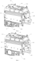
FIG. 1 is a schematic diagram illustrating a refrigerator according to an embodiment of the present disclosure. -
FIG. 2 is a schematic diagram illustrating the refrigerator viewed from another perspective according to the embodiment of the present disclosure. -
FIG. 3 is a schematic diagram illustrating a refrigerator bracket according to an embodiment of the present disclosure. -
FIG. 4 is a schematic diagram illustrating the refrigerator bracket viewed from another perspective according to the embodiment of the present disclosure. -
FIG. 5 is a schematic diagram illustrating a first frame of the refrigerator bracket according to an embodiment of the present disclosure. -
FIG. 6 is a schematic diagram illustrating a second frame of the refrigerator bracket according to an embodiment of the present disclosure. -
FIG. 7 is a partial cross-sectional view illustrating a connection between the first frame and the second frame of the refrigerator bracket according to an embodiment of the present disclosure. -
FIG. 8 is a schematic diagram illustrating a refrigerator according to an embodiment of the present disclosure with the refrigerator bracket being removed. -
FIG. 9 is a schematic diagram illustrating a cabinet and an evaporator of the refrigerator according to an embodiment of the present disclosure. -
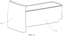
FIG. 10 is an assembly schematic diagram of a drawer and a door panel of the refrigerator according to an embodiment of the present disclosure. -
- 1. Refrigerator bracket; 11. First frame; 111. First installation site; 112. First groove; 113. Second groove; 114. First side wall; 115. Bottom wall; 116. Second side wall; 117. Third side wall; 12. Second frame; 121. Second installation site; 122. First installation plate; 123. Second installation plate; 124. Third installation site; 125. Fourth installation site; 126. Protrusion; 13. Fastener; 14. Installation cavity; 15. Placement opening; 16. Reinforcing rib;
- 2. Cooling fan;
- 3. Cabinet; 31. Storage room; 32. Pick-up port;
- 4. Refrigeration module; 41. Evaporator; 42. Compressor;
- 51. Drawer; 52. Door panel; 53. Drive motor;
- 6. Control box.
- Embodiments of the present disclosure are described in detail below, and examples of the embodiments are shown in the accompanying drawings. The embodiments described below with reference to the accompanying drawings are exemplary and intended to be used for explaining the present disclosure, and should not be understood as limiting the present disclosure.
- A
refrigerator bracket 1, a refrigerator having the same and an automobile according to embodiments of the present disclosure will be described below with reference toFIG. 1 to FIG. 10 . - As shown in
FIG. 1 to FIG. 7 , therefrigerator bracket 1 according to an embodiment of the present disclosure includes: afirst frame 11, asecond frame 12 andfasteners 13. Thefirst frame 11 is disposed on a side of thesecond frame 12 in a height direction, and thefirst frame 11 is detachably connected to thesecond frame 12 by thefasteners 13. Aninstallation cavity 14 is enclosed by thefirst frame 11 and thesecond frame 12, and aplacement opening 15 is disposed on one side of theinstallation cavity 14. - According to the
refrigerator bracket 1 of the embodiment of the present disclosure, theinstallation cavity 14 is enclosed by thefirst frame 11 and thesecond frame 12, and thefirst frame 11 and thesecond frame 12 are detachably connected, so that the number of components can be reduced, and the structure is simple, the assembly is convenient, and the production cost is low. - In some embodiments, as shown in
FIG. 4 to FIG. 7 , a plurality offirst installation sites 111 are disposed on thefirst frame 11, among the plurality offirst installation sites 111, at least some of thefirst installation sites 111 are spaced apart in a first direction (the left-to-right direction shown inFIG. 4 ). A plurality ofsecond installation sites 121 that are in one-to-one correspondence with the plurality offirst installation sites 111 are disposed on thesecond frame 12, and thefasteners 13 are connected to thefirst installation sites 111 and thesecond installation sites 121. - For example, each of the
first installation sites 111 is a through hole, each of thesecond installation sites 121 is a threaded groove, and thefastener 13 is a threaded member that passes through the through hole and is screwed into the threaded groove. Since there are a plurality offirst installation sites 111 andsecond installation sites 121, the firmness of the connection between thefirst frame 11 and thesecond frame 12 can be improved. - In some embodiments, as shown in
FIG. 1 to FIG. 7 , at least one of thefirst frame 11 and thesecond frame 12 is an injection molding member. In some embodiments, thefirst frame 11 and thesecond frame 12 are both injection molding members. For example, thefirst frame 11 is injection molding of PA6+GF30 material, and thesecond frame 12 is injection molding of PC+ABS material, which is beneficial to a lightweight design of therefrigerator bracket 1 and reduces the weight of the refrigerator. - In some embodiments, the plurality of
first installation sites 111 are divided into a plurality of groups, each group offirst installation sites 111 includes at least twofirst installation sites 111 spaced apart in a length direction of the first frame 11 (the front-to-back direction shown inFIG. 4 ), and the plurality of groups offirst installation sites 111 are spaced apart in the first direction (the left-to-right direction shown inFIG. 4 ). - In some embodiments, as shown in
FIG. 4 , the plurality offirst installation sites 111 are divided into two groups, the two groups offirst installation sites 111 are disposed opposite to each other on the left side and the right side of thefirst frame 11, and each group offirst installation sites 111 includes threefirst installation sites 111 spaced apart in the front-to-back direction. It can be understood that after each group offirst installation sites 111 and the correspondingsecond installation sites 121 are connected by thefasteners 13, the movement and rotation between thefirst frame 11 and thesecond frame 12 are restricted. After the plurality of groups offirst installation sites 111 and the correspondingsecond installation sites 121 are connected by thefasteners 13, the restriction effect is further improved and a plurality offasteners 13 share the shear force. - In some embodiments, as shown in
FIG. 7 , an outer wall of thefirst frame 11 is provided with afirst groove 112 opening upward and asecond groove 113 opening downward, thefirst groove 112 and thesecond groove 113 form the first installation site. Thefirst groove 112 and thesecond groove 113 are spaced apart in the up-to-down direction. The top of thesecond frame 12 includes aprotrusion 126 that forms thesecond installation site 121 and extends into thesecond groove 113. One end of thefastener 13 is located in thefirst groove 112, and the other end of thefastener 13 is connected to theprotrusion 126. It can be understood that when thefirst frame 11 and thesecond frame 12 are mounted, thefirst frame 11 is placed on thesecond frame 12 so that theprotrusion 126 extends into the correspondingsecond groove 113, thereby achieving the alignment and pre-fixation of thefirst frame 11 and thesecond frame 12. Then, thefastener 13 is passed through thefirst installation site 111 and thesecond installation site 121 to fix thefirst frame 11 and thesecond frame 12, thereby reducing the assembly difficulty of therefrigerator bracket 1 and improving the production efficiency. - In some embodiments, as shown in
FIG. 7 , the first frame includes afirst side wall 114, abottom wall 115, asecond side wall 116 and athird side wall 117. Thebottom wall 115 extends from the outer wall surface of thefirst side wall 114 along the first direction. The lower end of thesecond side wall 116 is connected to the free end of the bottom wall 115 (the right end as shown inFIG.7 ). Thefirst groove 112 is formed among thefirst side wall 114, thebottom wall 115 and thesecond side wall 116. The upper end of thethird side wall 117 is connected to the free end of thebottom wall 115. Thesecond groove 113 is formed between thebottom wall 115 and thethird side wall 117. - In some embodiments, the height of the
second side wall 116 is less than the height of thefirst side wall 114, so as to prevent thesecond side wall 116 from interfering with the installation of thefastener 13. - In some embodiments, a
first installation plate 122 and asecond installation plate 123 are provided at the lower end of thesecond frame 12, and thefirst installation plate 122 and thesecond installation plate 123 are spaced apart to define an installation space. - In some embodiments, as shown in
FIG. 4 , the length direction of thefirst installation plate 122 is disposed along the front-to-back direction, the length direction of thesecond installation plate 123 is disposed along the front-to-back direction, and thefirst installation plate 122 and thesecond installation plate 123 are arranged opposite to each other on a left side and a right side of thesecond frame 12. - In some embodiments, at least one of the
first installation plate 122 and thesecond installation plate 123 is provided with a heat dissipation hole. For example, both thefirst installation plate 122 and thesecond installation plate 123 are provided with a heat dissipation hole. - In some embodiments, the
first installation plate 122 and/or thesecond installation plate 123 are integrally formed with thesecond frame 12. For example, thefirst installation plate 122 is integrally formed with the left side plate of thesecond frame 12, and thesecond installation plate 123 is integrally formed with the right side plate of thesecond frame 12. It can be understood that thesecond frame 12 and the installation plate 17 are integrally formed, thereby reducing the number of assembled components and reducing the difficulty of assembly. - In some embodiments, the
second frame 12 is provided with athird installation site 124 that is located on thefirst installation plate 122 and/or thesecond installation plate 123. For example, thethird installation site 124 is located on thefirst installation plate 122 and thesecond installation plate 123, and components such as a coolingfan 2 and acompressor 42 can be mounted at thethird installation site 124, so that other auxiliary components of the refrigerator can be fixed to therefrigerator bracket 1. Accordingly, the structure of the refrigerator is compact, and there is no need to mount other brackets for fixing components, thereby reducing the production costs. - In some embodiments, as shown in
FIG. 2 and FIG. 3 , afourth installation site 125 for installing components of the refrigerator is disposed on a side wall of thesecond frame 12 away from theplacement opening 15. It can be understood that a back surface of thesecond frame 12 is provided with thefourth installation site 125, on which acontrol box 6 for controlling the operation of the refrigerator by a user can be mounted, and/or adrive motor 53 for driving opening and closing the door of the refrigerator can also be mounted, so that the use effect of therefrigerator bracket 1 can be better. - In some embodiments, as shown in
FIG. 1 to FIG. 4 , at least one of thefirst frame 11 and thesecond frame 12 is provided with a reinforcingrib 16. For example, both thefirst frame 11 and thesecond frame 12 are provided with the reinforcingrib 16. When thefirst frame 11 and thesecond frame 12 are injecting, the reinforcingrib 16 can be formed on thefirst frame 11 and thesecond frame 12 by injection molding, thereby improving the connection strength of thefirst frame 11 and thesecond frame 12 and extending the service life of therefrigerator bracket 1. - As shown in
FIG. 1 andFIG. 8 , a refrigerator according to an embodiment of the second aspect of the present disclosure includes acabinet 3 and arefrigerator bracket 1. Therefrigerator bracket 1 is therefrigerator bracket 1 of the embodiment of the present disclosure, and thecabinet 3 is disposed in theinstallation cavity 14. It can be understood that thecabinet 3 can be placed in theinstallation cavity 14 through theplacement opening 15. - According to the refrigerator of the embodiment of the present disclosure, an
installation cavity 14 is enclosed by thefirst frame 11 and thesecond frame 12, and thefirst frame 11 and thesecond frame 12 are detachably connected, so that the number of components can be reduced, and the structure is simple, the assembly is convenient, and the production cost is low. - In some embodiments, as shown in
FIG. 8 , the refrigerator further includes arefrigeration module 4 including anevaporator 41 and acompressor 42. Thecompressor 42 is connected to theevaporator 41, and thecompressor 42 is located outside thecabinet 3. Thecompressor 42 can exchange energy with theevaporator 41. Theevaporator 41 is covered on the outer peripheral wall of thecabinet 3, and theevaporator 41 can transfer cooling energy to the inside of thecabinet 3. For example, theevaporator 41 includes a cooling pipe that is coiled on the outer peripheral wall of thecabinet 3, so as to improve the refrigeration effect of the refrigerator. - As shown in
FIG. 9 , thecabinet 3 includes astorage room 31, and the side wall of thecabinet 3 is provided with a pick-upport 32 communicated with thestorage room 31. The refrigerator further includes adrawer 51 connected to thecabinet 3, and thedrawer 51 can move between an open position and a closed position. In the open position, thedrawer 51 extends out to the pick-upport 32, and in the closed position, thedrawer 51 is located in thestorage room 31. It can be understood that thedrawer 51 is a hollow structure, and items can be placed in thedrawer 51 and then sent to thestorage room 31 for refrigeration. When it is necessary to take or store items in thestorage room 31, the user can pull thedrawer 51 out of thestorage room 31, so that it is convenient for the user to operate and the use effect is better. - In some embodiments, as shown in
FIG. 1 andFIG. 10 , the refrigerator further includes adoor panel 52 connected to the drawer 5. In the closed position, thedoor panel 52 closes the pick-upport 32. In some embodiments, thedrawer 51 and thedoor panel 52 are detachably connected. For example, thedrawer 51 is connected to thedoor panel 52 by a screw or a clamping structure, so that it is easy to manufacture and assemble. Alternatively, thedrawer 51 and thedoor panel 52 are integrally formed, so that the structural strength is high and the service life is long. - An automobile according to an embodiment of the third aspect of the present disclosure includes a vehicle body and a
refrigerator 3 that is therefrigerator 3 of the embodiment of the second aspect of the present disclosure. Therefrigerator 3 is disposed on the vehicle body. It can be understood that therefrigerator 3 can be mounted on the vehicle body through therefrigerator bracket 1. - In the description of the present disclosure, it should be understood that orientations or positional relationships indicated by terms, such as "center", "longitudinal", "lateral", "length", "width", "thickness", "up", "down", "front", "back", "left", "right", "vertical", "horizontal", "top", "bottom", "inside", "outside", "clockwise", "counterclockwise", "axial", "radial", "circumferential", are based on the orientations or positional relationships shown in the accompanying drawings, and are only for the convenience of describing the present disclosure and simplifying the description, and do not indicate or imply that a device or element to which the orientations or positional relationships referred must have a specific orientation, be constructed and operated in a specific orientation, and therefore should not be understood as a limitation on the present disclosure.
- In addition, the terms "first" and "second" are merely used for descriptive purposes and should not be understood as indicating or implying relative importance or implicitly indicating the number of technical features indicated. Thus, a feature defined as "first" or "second" may explicitly or implicitly include at least one of the features. In the description of the present disclosure, "plurality" means at least two, for example, two, three, etc., unless otherwise clearly and specifically defined.
- In the present disclosure, unless otherwise clearly stipulated and limited, terms such as "mounted", "communicated", "connected", "fixed" and the like should be understood in a broad sense. For example, it can be a fixed connection, a detachable connection, or an integral structure; it can be a mechanical connection, an electrical connection, or communicative with each other; it can be directly connected or indirectly connected through an intermediate medium; it can be the internal connection of two elements or the interaction relationship between two elements, unless otherwise clearly limited. For those skilled in the art, the specific meanings of the above terms in the present disclosure can be understood according to specific circumstances.
- In the present disclosure, unless otherwise clearly specified and limited, a first feature being "on"/"below" a second feature may mean that the first and second features are in direct contact with each other, or the first and second features are in indirect contact with each other through an intermediate medium. Moreover, a first feature being "above", "on" and "on top" of the second feature may mean that the first feature is directly above or obliquely above the second feature, or simply means that the first feature is at a higher horizontal height than the second feature. A first feature being "below" or "beneath" a second feature may mean that the first feature is directly below or diagonally below the second feature, or simply means that the first feature is at a lower horizontal height than the second feature.
- In the present disclosure, the terms "one embodiment", "some embodiments", "example", "specific example", or "some examples" etc. mean that the specific features, structures, materials or characteristics described in conjunction with the embodiment or examples are included in at least one embodiment or example of the present disclosure. In this specification, the schematic representations of the above terms do not necessarily refer to the same embodiment or example. Moreover, the specific features, structures, materials or characteristics described can be combined in any one or more embodiments or examples in a suitable manner. Furthermore, those skilled in the art may combine and associate different embodiments or examples and features of different embodiments or examples described in this specification without mutual contradiction.
- Although the above embodiments have been illustrated and described, it can be understood that the above embodiments are exemplary and should not to be construed as limitations of the present disclosure. Changes, modifications, substitutions and variations of the above embodiments by those skilled in the art are all within the scope of protection of the present disclosure.
Claims (11)
- A refrigerator bracket, comprising: a first frame, a second frame and fasteners, characterized in that the first frame is disposed on a side of the second frame in a height direction, the first frame is detachably connected to the second frame by the fasteners, an installation cavity is enclosed between the first frame and the second frame, and a placement opening is disposed on one side of the installation cavity.
- The refrigerator bracket according to claim 1, characterized in that the first frame is provided with a plurality of first installation sites, at least some of the plurality of first installation sites are spaced apart in a first direction, and the first direction is orthogonal to a length direction and a height direction of the first frame; the second frame is provided with a plurality of second installation sites that are in one-to-one correspondence with the plurality of first installation sites, and the fasteners are connected to the first installation sites and the second installation sites.
- The refrigerator bracket according to claim 2, characterized in that the plurality of first installation sites are divided into a plurality of groups, each group of first installation sites comprises at least two first installation sites spaced apart along the length direction of the first frame, and the plurality of groups of first installation sites are spaced apart in the first direction.
- The refrigerator bracket according to claim 2, characterized in that an outer wall surface of the first frame is provided with a first groove opening upward and a second groove opening downward, the first groove and the second groove form the first installation site, and the first groove and the second groove are spaced apart in an up and down direction; a top of the second frame is provided with a protrusion, the protrusion forms the second installation site and extends into the second groove, one end of the fastener is located in the first groove, and the other end of the fastener is connected to the protrusion.
- The refrigerator bracket according to claim 4, characterized in that the first frame comprises a first side wall, a bottom wall, a second side wall and a third side wall; the bottom wall extends from an outer wall surface of the first side wall along the first direction, a lower end of the second side wall is connected to a free end of the bottom wall, the first groove is formed among the first side wall, the bottom wall and the second side wall, an upper end of the third side wall is connected to the free end of the bottom wall, and the second groove is formed between the bottom wall and the third side wall.
- The refrigerator bracket according to claim 5, characterized in that a height of the second side wall is less than a height of the first side wall.
- The refrigerator bracket according to any one of claims 1 to 6, characterized in that a lower end of the second frame is provided with a first installation plate and a second installation plate that are spaced apart to define an installation space.
- The refrigerator bracket according to claim 7, characterized in that at least one of the first installation plate and the second installation plate is provided with a heat dissipation hole.
- The refrigerator bracket according to any one of claims 1 to 8, characterized in that at least one of the first frame and the second frame is an injection molding member.
- A refrigerator, characterized in that the refrigerator comprises a cabinet and a refrigerator bracket; and
the refrigerator bracket is the refrigerator bracket according to any one of claims 1 to 9, and the cabinet is disposed in the installation cavity. - An automobile, comprising a vehicle body and a refrigerator, characterized in that the refrigerator is disposed on the vehicle body, and the refrigerator is the refrigerator according to claim 10.
Applications Claiming Priority (3)
| Application Number | Priority Date | Filing Date | Title |
|---|---|---|---|
| CN202220505946 | 2022-03-09 | ||
| CN202220608111.0U CN217785544U (en) | 2022-03-09 | 2022-03-18 | Refrigerator support and refrigerator and automobile with same |
| PCT/CN2023/079502 WO2023169317A1 (en) | 2022-03-09 | 2023-03-03 | Refrigerator stand and refrigerator having same, and automobile |
Publications (2)
| Publication Number | Publication Date |
|---|---|
| EP4474736A1 true EP4474736A1 (en) | 2024-12-11 |
| EP4474736A4 EP4474736A4 (en) | 2025-05-07 |
Family
ID=83348455
Family Applications (3)
| Application Number | Title | Priority Date | Filing Date |
|---|---|---|---|
| EP23765895.0A Withdrawn EP4474736A4 (en) | 2022-03-09 | 2023-03-03 | REFRIGERATOR STAND AND REFRIGERATOR WITH IT AS WELL AS AUTOMOBILE |
| EP23766021.2A Pending EP4477976A4 (en) | 2022-03-09 | 2023-03-07 | Refrigerator and vehicle |
| EP23766022.0A Pending EP4491453A4 (en) | 2022-03-09 | 2023-03-07 | Onboard refrigerator and automobile |
Family Applications After (2)
| Application Number | Title | Priority Date | Filing Date |
|---|---|---|---|
| EP23766021.2A Pending EP4477976A4 (en) | 2022-03-09 | 2023-03-07 | Refrigerator and vehicle |
| EP23766022.0A Pending EP4491453A4 (en) | 2022-03-09 | 2023-03-07 | Onboard refrigerator and automobile |
Country Status (4)
| Country | Link |
|---|---|
| US (3) | US20250196748A1 (en) |
| EP (3) | EP4474736A4 (en) |
| CN (8) | CN217686057U (en) |
| WO (4) | WO2023169317A1 (en) |
Families Citing this family (11)
| Publication number | Priority date | Publication date | Assignee | Title |
|---|---|---|---|---|
| CN217686057U (en) * | 2022-03-09 | 2022-10-28 | 北京车和家汽车科技有限公司 | Refrigerator and vehicle with same |
| CN116971707A (en) * | 2023-01-12 | 2023-10-31 | 上海理想汽车科技有限公司 | Refrigerator seal, car refrigerator and vehicle |
| EP4650693A4 (en) * | 2023-01-12 | 2026-04-15 | Shanghai Lixiang Automobile Co Ltd | Refrigerator seal, vehicle-mounted refrigerator and vehicle |
| KR20240176515A (en) * | 2023-06-16 | 2024-12-24 | 현대자동차주식회사 | Center console device for vehicle |
| CN117022121A (en) * | 2023-07-19 | 2023-11-10 | 小米汽车科技有限公司 | Trunk assembly and vehicle |
| CN220947700U (en) * | 2023-09-14 | 2024-05-14 | 上海理想汽车科技有限公司 | Vehicle-mounted temperature adjusting box and vehicle |
| CN117698540B (en) * | 2023-12-07 | 2026-04-14 | 英得尔实业(广东)股份有限公司 | Vehicle-mounted refrigerator with top opening and back opening and control method thereof |
| WO2025201542A1 (en) * | 2024-03-28 | 2025-10-02 | 上海理想汽车科技有限公司 | Sliding assembly, vehicle-mounted refrigerator, storage box, and vehicle |
| CN118500025B (en) * | 2024-06-20 | 2025-02-07 | 宁波惠康工业科技股份有限公司 | Anti-condensation structure of the wall of the car refrigerator |
| CN222993279U (en) * | 2024-06-25 | 2025-06-17 | 比亚迪股份有限公司 | Car refrigerator, thermal management system and vehicle |
| CN120116856B (en) * | 2025-05-13 | 2025-09-09 | 比亚迪股份有限公司 | Vehicle armrest storage structure and vehicle |
Family Cites Families (58)
| Publication number | Priority date | Publication date | Assignee | Title |
|---|---|---|---|---|
| FR2193186A1 (en) * | 1972-07-20 | 1974-02-15 | Soissonnais Manufacture | |
| JPH0540783U (en) * | 1991-10-23 | 1993-06-01 | ホシザキ電機株式会社 | Storage |
| KR0129470B1 (en) * | 1993-10-10 | 1998-04-04 | 전성원 | Glove box opening device |
| JPH08145527A (en) * | 1994-11-17 | 1996-06-07 | Nippon Trailmobile Co Ltd | Refrigerator vehicle |
| CN2254166Y (en) * | 1996-04-08 | 1997-05-14 | 冯亦王 | Additional air conditioner and refrigerator device for car |
| DE19811185C1 (en) * | 1998-03-14 | 1999-07-01 | Daimler Chrysler Ag | Cold storage box for comestibles in motor vehicle |
| KR200218537Y1 (en) * | 2000-10-31 | 2001-04-02 | 채명현 | mini portable freezer |
| JP2003279243A (en) * | 2002-03-25 | 2003-10-02 | Sanyo Electric Co Ltd | Refrigerator |
| KR20030085224A (en) * | 2002-04-29 | 2003-11-05 | 위니아만도 주식회사 | A Car Refrigerator and Heating Method for Vehicles |
| JP2004028498A (en) * | 2002-06-27 | 2004-01-29 | Hitachi Home & Life Solutions Inc | refrigerator |
| KR100487317B1 (en) * | 2002-07-26 | 2005-05-03 | 엘지전자 주식회사 | direct cooling type refrigerator |
| CN1206501C (en) * | 2002-08-19 | 2005-06-15 | 乐金电子(天津)电器有限公司 | Cold air supply device of refrigerator |
| DE20215882U1 (en) * | 2002-10-16 | 2003-01-30 | Demuth, Ulrich, 64711 Erbach | Drink and food holder for motor vehicle interior is mounted on dashboard and has heating or cooling device |
| KR100498381B1 (en) * | 2002-12-06 | 2005-07-01 | 엘지전자 주식회사 | Side by side type refrigerator with vegetable storing room capable of heating |
| US6895762B1 (en) * | 2004-07-26 | 2005-05-24 | Ching-Yu Lin | Refrigerator with a freezer area and a refrigeration area |
| CN1766471A (en) * | 2004-10-27 | 2006-05-03 | 乐金电子(天津)电器有限公司 | Sauerkraut refrigerator |
| KR20070005184A (en) * | 2005-07-05 | 2007-01-10 | 엘지전자 주식회사 | How to Store Cheonggukjang in Kimchi Refrigerator |
| KR101319434B1 (en) * | 2005-12-27 | 2013-10-17 | 한라비스테온공조 주식회사 | A cooling and heating cabinet device of rear seat for vehicle using thermoelectric element |
| KR20070075677A (en) * | 2006-01-14 | 2007-07-24 | 삼성전자주식회사 | Refrigerator and supercooling liquid manufacturing method using same |
| KR200425896Y1 (en) * | 2006-06-29 | 2006-09-07 | 김원일 | Drawer lock |
| DE102007043213B4 (en) * | 2006-09-18 | 2015-04-02 | Mo.T.I.S. Gmbh | Refrigerator for commercial vehicle cabins |
| KR101210410B1 (en) * | 2006-09-25 | 2012-12-10 | 한라공조주식회사 | Refrigerator for a automotive vehicles |
| KR100795885B1 (en) * | 2006-10-23 | 2008-01-21 | 주식회사 대창 | Car cold storage |
| JP5194960B2 (en) * | 2007-04-20 | 2013-05-08 | パナソニック株式会社 | Air purification apparatus and air conditioner or refrigerator using the same |
| JP2009030922A (en) * | 2007-07-30 | 2009-02-12 | Panasonic Corp | Direct cooling refrigerator |
| KR20120082992A (en) * | 2011-01-17 | 2012-07-25 | 삼성전자주식회사 | Refrigerator |
| CN102409922A (en) * | 2011-09-09 | 2012-04-11 | 宁波亚大安全设备制造有限公司 | Drawer type vehicle-mounted safety box |
| CN102564032A (en) * | 2012-03-01 | 2012-07-11 | 合肥美的荣事达电冰箱有限公司 | Refrigerator |
| JP2013220711A (en) * | 2012-04-16 | 2013-10-28 | Toyoda Gosei Co Ltd | Double door storage box |
| DE102012209938A1 (en) * | 2012-06-13 | 2013-12-19 | BSH Bosch und Siemens Hausgeräte GmbH | The refrigerator |
| CN203047078U (en) * | 2012-12-17 | 2013-07-10 | 北汽福田汽车股份有限公司 | Vehicle-mounted storage box mechanism |
| CN103175375A (en) * | 2013-03-19 | 2013-06-26 | 合肥晶弘电器有限公司 | Refrigerating and freshness retaining storage method of refrigerator |
| CN203472628U (en) * | 2013-09-24 | 2014-03-12 | 周小能 | Vehicle-mounted refrigerator |
| CN103738249B (en) * | 2014-01-22 | 2015-10-28 | 上海延锋江森座椅有限公司 | A kind of storage box device of car seat |
| DE102014201566A1 (en) * | 2014-01-29 | 2015-07-30 | Volkswagen Aktiengesellschaft | Side panel for a vehicle |
| CN204519879U (en) * | 2015-04-08 | 2015-08-05 | 浙江黄岩侨丰塑料制品厂 | Transparent receiver |
| FR3042454B1 (en) * | 2015-10-15 | 2019-05-03 | Renault S.A.S. | SLIDING DRAWER STORAGE DEVICE, IN PARTICULAR FOR A MOTOR VEHICLE |
| CN205381508U (en) * | 2016-02-19 | 2016-07-13 | 李红卫 | Storage box |
| CN106080409B (en) * | 2016-07-18 | 2019-08-27 | 王冠文 | Vehicle-mounted storage box and its drawer |
| CN206031154U (en) * | 2016-09-14 | 2017-03-22 | 格拉默车辆内饰(上海)有限公司 | Take automobile console cold -stored freezing and heating and thermal insulation function |
| CN106515595B (en) * | 2017-01-06 | 2019-01-25 | 上海延锋金桥汽车饰件系统有限公司 | A two-way openable storage box |
| CN107014130B (en) * | 2017-03-28 | 2020-01-21 | 青岛海尔特种电冰柜有限公司 | refrigeration unit |
| KR20170047204A (en) * | 2017-04-24 | 2017-05-04 | 주식회사 윈텍 | Built-in type refrigerator |
| CN209197288U (en) * | 2018-10-15 | 2019-08-02 | 青岛海尔股份有限公司 | Refrigerator |
| JP7217414B2 (en) * | 2018-10-23 | 2023-02-03 | パナソニックIpマネジメント株式会社 | refrigerator |
| FR3100503B1 (en) * | 2019-09-09 | 2021-07-30 | Renault Sas | DRAWER STORAGE DEVICE OF A MOTOR VEHICLE |
| CN110953802B (en) * | 2019-12-09 | 2021-06-15 | 海信(山东)冰箱有限公司 | a refrigerator |
| CN212566475U (en) * | 2020-05-09 | 2021-02-19 | 广东英得尔实业发展有限公司 | Drawer and vehicle-mounted refrigerator |
| CN212979805U (en) * | 2020-06-28 | 2021-04-16 | 雷铁显 | Vehicle-mounted refrigerator |
| US20220034580A1 (en) * | 2020-07-29 | 2022-02-03 | Bernard Smith | Portable Refrigerator Assembly |
| CN213020506U (en) * | 2020-09-16 | 2021-04-20 | 合肥华凌股份有限公司 | Drawer device and refrigeration equipment having the same |
| CN214246944U (en) * | 2020-10-09 | 2021-09-21 | 多美达(深圳)电器有限公司 | Door lock structure |
| CN215097310U (en) * | 2021-04-01 | 2021-12-10 | 长城汽车股份有限公司 | Automobile-used electronic storing box and car |
| CN214841888U (en) * | 2021-04-13 | 2021-11-23 | 佛山市艾凯电器有限公司 | A cold and hot car refrigerator |
| CN215097309U (en) * | 2021-06-16 | 2021-12-10 | 长城汽车股份有限公司 | Storing box assembly and vehicle seat |
| CN215864269U (en) * | 2021-06-29 | 2022-02-18 | 合肥美的电冰箱有限公司 | Locking subassembly and locker |
| CN113829998A (en) * | 2021-09-24 | 2021-12-24 | 东风李尔汽车座椅有限公司技术中心 | storage box |
| CN217686057U (en) * | 2022-03-09 | 2022-10-28 | 北京车和家汽车科技有限公司 | Refrigerator and vehicle with same |
-
2022
- 2022-03-18 CN CN202220608723.XU patent/CN217686057U/en active Active
- 2022-03-18 CN CN202210272959.5A patent/CN115451632B/en active Active
- 2022-03-18 CN CN202210272960.8A patent/CN115465193B/en active Active
- 2022-03-18 CN CN202210272958.0A patent/CN115465173B/en active Active
- 2022-03-18 CN CN202220608815.8U patent/CN217495988U/en active Active
- 2022-03-18 CN CN202220608813.9U patent/CN217686058U/en active Active
- 2022-03-18 CN CN202220608724.4U patent/CN217672315U/en active Active
- 2022-03-18 CN CN202220608111.0U patent/CN217785544U/en active Active
-
2023
- 2023-03-03 WO PCT/CN2023/079502 patent/WO2023169317A1/en not_active Ceased
- 2023-03-03 EP EP23765895.0A patent/EP4474736A4/en not_active Withdrawn
- 2023-03-03 US US18/844,459 patent/US20250196748A1/en active Pending
- 2023-03-07 US US18/844,439 patent/US20250146740A1/en active Pending
- 2023-03-07 WO PCT/CN2023/080172 patent/WO2023169444A1/en not_active Ceased
- 2023-03-07 WO PCT/CN2023/080170 patent/WO2023169443A1/en not_active Ceased
- 2023-03-07 EP EP23766021.2A patent/EP4477976A4/en active Pending
- 2023-03-07 US US18/844,828 patent/US20250146733A1/en active Pending
- 2023-03-07 EP EP23766022.0A patent/EP4491453A4/en active Pending
- 2023-03-09 WO PCT/CN2023/080595 patent/WO2023169531A1/en not_active Ceased
Also Published As
| Publication number | Publication date |
|---|---|
| WO2023169443A1 (en) | 2023-09-14 |
| EP4477976A4 (en) | 2025-05-07 |
| CN115451632A (en) | 2022-12-09 |
| EP4491453A1 (en) | 2025-01-15 |
| EP4474736A4 (en) | 2025-05-07 |
| US20250146740A1 (en) | 2025-05-08 |
| CN115451632B (en) | 2024-09-13 |
| CN217686057U (en) | 2022-10-28 |
| CN115465193B (en) | 2025-08-01 |
| EP4491453A4 (en) | 2025-05-07 |
| CN115465193A (en) | 2022-12-13 |
| CN115465173B (en) | 2025-11-18 |
| WO2023169443A8 (en) | 2024-08-29 |
| WO2023169531A1 (en) | 2023-09-14 |
| CN217672315U (en) | 2022-10-28 |
| CN217785544U (en) | 2022-11-11 |
| US20250146733A1 (en) | 2025-05-08 |
| WO2023169317A1 (en) | 2023-09-14 |
| US20250196748A1 (en) | 2025-06-19 |
| WO2023169444A1 (en) | 2023-09-14 |
| CN115465173A (en) | 2022-12-13 |
| CN217495988U (en) | 2022-09-27 |
| EP4477976A1 (en) | 2024-12-18 |
| CN217686058U (en) | 2022-10-28 |
Similar Documents
| Publication | Publication Date | Title |
|---|---|---|
| US20250196748A1 (en) | Refrigerator bracket and refrigerator having same, and automobile | |
| US8047017B2 (en) | Refrigerator and evaporator mounting structure therefor | |
| WO2020038239A1 (en) | Window air conditioner | |
| KR20190106490A (en) | Refrigerator | |
| US10724783B2 (en) | Household refrigerator with an opening device for a door or drawer | |
| KR20140020738A (en) | Door opening apparatus and refrigerator | |
| CN111536741A (en) | Refrigerator with a door | |
| CN215175505U (en) | Air conditioner | |
| CN119629945A (en) | A cooling and heat dissipation structure and a cooling and heat dissipation frequency conversion integrated machine | |
| US20080087025A1 (en) | Evaporator fan with shroud assembly | |
| CN207515335U (en) | Cabin structure and refrigerator | |
| CN215597454U (en) | Air conditioner indoor unit and air conditioner | |
| CN1213268C (en) | Mechanical chamber fan motor installation stand for electric refrigerator | |
| JP3640498B2 (en) | Pass-through refrigerator | |
| CN218410146U (en) | Air conditioner and energy storage container | |
| CN209689012U (en) | Ducting part and air conditioner indoor unit with it | |
| CN216797166U (en) | Vertical showcase heat radiation structure capable of reducing energy consumption | |
| CN222785829U (en) | Motor components and air conditioners | |
| CN217979057U (en) | Window type air conditioner | |
| CN222703586U (en) | Storage device | |
| CN215447010U (en) | Refrigerator with cold guiding plate | |
| CN222363977U (en) | Duct type air conditioner indoor unit, air conditioner | |
| CN223179138U (en) | Fixing device and refrigerator installation structure | |
| CN220187211U (en) | Heating and cooling cabinet | |
| US20260078940A1 (en) | Vehicle refrigerator |
Legal Events
| Date | Code | Title | Description |
|---|---|---|---|
| STAA | Information on the status of an ep patent application or granted ep patent |
Free format text: STATUS: THE INTERNATIONAL PUBLICATION HAS BEEN MADE |
|
| PUAI | Public reference made under article 153(3) epc to a published international application that has entered the european phase |
Free format text: ORIGINAL CODE: 0009012 |
|
| STAA | Information on the status of an ep patent application or granted ep patent |
Free format text: STATUS: REQUEST FOR EXAMINATION WAS MADE |
|
| 17P | Request for examination filed |
Effective date: 20240905 |
|
| AK | Designated contracting states |
Kind code of ref document: A1 Designated state(s): AL AT BE BG CH CY CZ DE DK EE ES FI FR GB GR HR HU IE IS IT LI LT LU LV MC ME MK MT NL NO PL PT RO RS SE SI SK SM TR |
|
| REG | Reference to a national code |
Ref country code: DE Ref legal event code: R079 Free format text: PREVIOUS MAIN CLASS: F25D0011000000 Ipc: F25D0017060000 |
|
| A4 | Supplementary search report drawn up and despatched |
Effective date: 20250404 |
|
| RIC1 | Information provided on ipc code assigned before grant |
Ipc: B60R 7/04 20060101ALI20250401BHEP Ipc: F25D 17/06 20060101AFI20250401BHEP |
|
| DAV | Request for validation of the european patent (deleted) | ||
| DAX | Request for extension of the european patent (deleted) | ||
| STAA | Information on the status of an ep patent application or granted ep patent |
Free format text: STATUS: THE APPLICATION IS DEEMED TO BE WITHDRAWN |
|
| 18D | Application deemed to be withdrawn |
Effective date: 20251025 |