EP4474734A1 - Heat exchanger and air-conditioning device - Google Patents
Heat exchanger and air-conditioning device Download PDFInfo
- Publication number
- EP4474734A1 EP4474734A1 EP22924754.9A EP22924754A EP4474734A1 EP 4474734 A1 EP4474734 A1 EP 4474734A1 EP 22924754 A EP22924754 A EP 22924754A EP 4474734 A1 EP4474734 A1 EP 4474734A1
- Authority
- EP
- European Patent Office
- Prior art keywords
- refrigerant
- heat exchange
- exchange module
- rows
- leeward
- Prior art date
- Legal status (The legal status is an assumption and is not a legal conclusion. Google has not performed a legal analysis and makes no representation as to the accuracy of the status listed.)
- Withdrawn
Links
Images













Classifications
-
- F—MECHANICAL ENGINEERING; LIGHTING; HEATING; WEAPONS; BLASTING
- F28—HEAT EXCHANGE IN GENERAL
- F28D—HEAT-EXCHANGE APPARATUS, NOT PROVIDED FOR IN ANOTHER SUBCLASS, IN WHICH THE HEAT-EXCHANGE MEDIA DO NOT COME INTO DIRECT CONTACT
- F28D1/00—Heat-exchange apparatus having stationary conduit assemblies for one heat-exchange medium only, the media being in contact with different sides of the conduit wall, in which the other heat-exchange medium is a large body of fluid, e.g. domestic or motor car radiators
- F28D1/02—Heat-exchange apparatus having stationary conduit assemblies for one heat-exchange medium only, the media being in contact with different sides of the conduit wall, in which the other heat-exchange medium is a large body of fluid, e.g. domestic or motor car radiators with heat-exchange conduits immersed in the body of fluid
- F28D1/04—Heat-exchange apparatus having stationary conduit assemblies for one heat-exchange medium only, the media being in contact with different sides of the conduit wall, in which the other heat-exchange medium is a large body of fluid, e.g. domestic or motor car radiators with heat-exchange conduits immersed in the body of fluid with tubular conduits
- F28D1/053—Heat-exchange apparatus having stationary conduit assemblies for one heat-exchange medium only, the media being in contact with different sides of the conduit wall, in which the other heat-exchange medium is a large body of fluid, e.g. domestic or motor car radiators with heat-exchange conduits immersed in the body of fluid with tubular conduits the conduits being straight
- F28D1/0535—Heat-exchange apparatus having stationary conduit assemblies for one heat-exchange medium only, the media being in contact with different sides of the conduit wall, in which the other heat-exchange medium is a large body of fluid, e.g. domestic or motor car radiators with heat-exchange conduits immersed in the body of fluid with tubular conduits the conduits being straight the conduits having a non-circular cross-section
- F28D1/05366—Assemblies of conduits connected to common headers, e.g. core type radiators
- F28D1/05383—Assemblies of conduits connected to common headers, e.g. core type radiators with multiple rows of conduits or with multi-channel conduits
-
- F—MECHANICAL ENGINEERING; LIGHTING; HEATING; WEAPONS; BLASTING
- F28—HEAT EXCHANGE IN GENERAL
- F28F—DETAILS OF HEAT-EXCHANGE AND HEAT-TRANSFER APPARATUS, OF GENERAL APPLICATION
- F28F9/00—Casings; Header boxes; Auxiliary supports for elements; Auxiliary members within casings
- F28F9/02—Header boxes; End plates
- F28F9/0246—Arrangements for connecting header boxes with flow lines
-
- F—MECHANICAL ENGINEERING; LIGHTING; HEATING; WEAPONS; BLASTING
- F25—REFRIGERATION OR COOLING; COMBINED HEATING AND REFRIGERATION SYSTEMS; HEAT PUMP SYSTEMS; MANUFACTURE OR STORAGE OF ICE; LIQUEFACTION SOLIDIFICATION OF GASES
- F25B—REFRIGERATION MACHINES, PLANTS OR SYSTEMS; COMBINED HEATING AND REFRIGERATION SYSTEMS; HEAT PUMP SYSTEMS
- F25B13/00—Compression machines, plants or systems, with reversible cycle
-
- F—MECHANICAL ENGINEERING; LIGHTING; HEATING; WEAPONS; BLASTING
- F25—REFRIGERATION OR COOLING; COMBINED HEATING AND REFRIGERATION SYSTEMS; HEAT PUMP SYSTEMS; MANUFACTURE OR STORAGE OF ICE; LIQUEFACTION SOLIDIFICATION OF GASES
- F25B—REFRIGERATION MACHINES, PLANTS OR SYSTEMS; COMBINED HEATING AND REFRIGERATION SYSTEMS; HEAT PUMP SYSTEMS
- F25B39/00—Evaporators; Condensers
-
- F—MECHANICAL ENGINEERING; LIGHTING; HEATING; WEAPONS; BLASTING
- F25—REFRIGERATION OR COOLING; COMBINED HEATING AND REFRIGERATION SYSTEMS; HEAT PUMP SYSTEMS; MANUFACTURE OR STORAGE OF ICE; LIQUEFACTION SOLIDIFICATION OF GASES
- F25B—REFRIGERATION MACHINES, PLANTS OR SYSTEMS; COMBINED HEATING AND REFRIGERATION SYSTEMS; HEAT PUMP SYSTEMS
- F25B41/00—Fluid-circulation arrangements
- F25B41/40—Fluid line arrangements
- F25B41/42—Arrangements for diverging or converging flows, e.g. branch lines or junctions
-
- F—MECHANICAL ENGINEERING; LIGHTING; HEATING; WEAPONS; BLASTING
- F28—HEAT EXCHANGE IN GENERAL
- F28D—HEAT-EXCHANGE APPARATUS, NOT PROVIDED FOR IN ANOTHER SUBCLASS, IN WHICH THE HEAT-EXCHANGE MEDIA DO NOT COME INTO DIRECT CONTACT
- F28D1/00—Heat-exchange apparatus having stationary conduit assemblies for one heat-exchange medium only, the media being in contact with different sides of the conduit wall, in which the other heat-exchange medium is a large body of fluid, e.g. domestic or motor car radiators
- F28D1/02—Heat-exchange apparatus having stationary conduit assemblies for one heat-exchange medium only, the media being in contact with different sides of the conduit wall, in which the other heat-exchange medium is a large body of fluid, e.g. domestic or motor car radiators with heat-exchange conduits immersed in the body of fluid
- F28D1/04—Heat-exchange apparatus having stationary conduit assemblies for one heat-exchange medium only, the media being in contact with different sides of the conduit wall, in which the other heat-exchange medium is a large body of fluid, e.g. domestic or motor car radiators with heat-exchange conduits immersed in the body of fluid with tubular conduits
- F28D1/053—Heat-exchange apparatus having stationary conduit assemblies for one heat-exchange medium only, the media being in contact with different sides of the conduit wall, in which the other heat-exchange medium is a large body of fluid, e.g. domestic or motor car radiators with heat-exchange conduits immersed in the body of fluid with tubular conduits the conduits being straight
- F28D1/0535—Heat-exchange apparatus having stationary conduit assemblies for one heat-exchange medium only, the media being in contact with different sides of the conduit wall, in which the other heat-exchange medium is a large body of fluid, e.g. domestic or motor car radiators with heat-exchange conduits immersed in the body of fluid with tubular conduits the conduits being straight the conduits having a non-circular cross-section
- F28D1/05366—Assemblies of conduits connected to common headers, e.g. core type radiators
- F28D1/05391—Assemblies of conduits connected to common headers, e.g. core type radiators with multiple rows of conduits or with multi-channel conduits combined with a particular flow pattern, e.g. multi-row multi-stage radiators
-
- F—MECHANICAL ENGINEERING; LIGHTING; HEATING; WEAPONS; BLASTING
- F28—HEAT EXCHANGE IN GENERAL
- F28F—DETAILS OF HEAT-EXCHANGE AND HEAT-TRANSFER APPARATUS, OF GENERAL APPLICATION
- F28F9/00—Casings; Header boxes; Auxiliary supports for elements; Auxiliary members within casings
- F28F9/02—Header boxes; End plates
- F28F9/026—Header boxes; End plates with static flow control means, e.g. with means for uniformly distributing heat exchange media into conduits
- F28F9/027—Header boxes; End plates with static flow control means, e.g. with means for uniformly distributing heat exchange media into conduits in the form of distribution pipes
- F28F9/0275—Header boxes; End plates with static flow control means, e.g. with means for uniformly distributing heat exchange media into conduits in the form of distribution pipes with multiple branch pipes
-
- F—MECHANICAL ENGINEERING; LIGHTING; HEATING; WEAPONS; BLASTING
- F28—HEAT EXCHANGE IN GENERAL
- F28F—DETAILS OF HEAT-EXCHANGE AND HEAT-TRANSFER APPARATUS, OF GENERAL APPLICATION
- F28F9/00—Casings; Header boxes; Auxiliary supports for elements; Auxiliary members within casings
- F28F9/02—Header boxes; End plates
- F28F9/026—Header boxes; End plates with static flow control means, e.g. with means for uniformly distributing heat exchange media into conduits
- F28F9/0278—Header boxes; End plates with static flow control means, e.g. with means for uniformly distributing heat exchange media into conduits in the form of stacked distribution plates or perforated plates arranged over end plates
-
- F—MECHANICAL ENGINEERING; LIGHTING; HEATING; WEAPONS; BLASTING
- F28—HEAT EXCHANGE IN GENERAL
- F28D—HEAT-EXCHANGE APPARATUS, NOT PROVIDED FOR IN ANOTHER SUBCLASS, IN WHICH THE HEAT-EXCHANGE MEDIA DO NOT COME INTO DIRECT CONTACT
- F28D21/00—Heat-exchange apparatus not covered by any of the groups F28D1/00 - F28D20/00
- F28D2021/0019—Other heat exchangers for particular applications; Heat exchange systems not otherwise provided for
- F28D2021/0068—Other heat exchangers for particular applications; Heat exchange systems not otherwise provided for for refrigerant cycles
-
- F—MECHANICAL ENGINEERING; LIGHTING; HEATING; WEAPONS; BLASTING
- F28—HEAT EXCHANGE IN GENERAL
- F28F—DETAILS OF HEAT-EXCHANGE AND HEAT-TRANSFER APPARATUS, OF GENERAL APPLICATION
- F28F1/00—Tubular elements; Assemblies of tubular elements
- F28F1/10—Tubular elements and assemblies thereof with means for increasing heat-transfer area, e.g. with fins, with projections, with recesses
- F28F1/12—Tubular elements and assemblies thereof with means for increasing heat-transfer area, e.g. with fins, with projections, with recesses the means being only outside the tubular element
- F28F1/24—Tubular elements and assemblies thereof with means for increasing heat-transfer area, e.g. with fins, with projections, with recesses the means being only outside the tubular element and extending transversely
- F28F1/32—Tubular elements and assemblies thereof with means for increasing heat-transfer area, e.g. with fins, with projections, with recesses the means being only outside the tubular element and extending transversely the means having portions engaging further tubular elements
-
- F—MECHANICAL ENGINEERING; LIGHTING; HEATING; WEAPONS; BLASTING
- F28—HEAT EXCHANGE IN GENERAL
- F28F—DETAILS OF HEAT-EXCHANGE AND HEAT-TRANSFER APPARATUS, OF GENERAL APPLICATION
- F28F9/00—Casings; Header boxes; Auxiliary supports for elements; Auxiliary members within casings
- F28F9/22—Arrangements for directing heat-exchange media into successive compartments, e.g. arrangements of guide plates
- F28F2009/222—Particular guide plates, baffles or deflectors, e.g. having particular orientation relative to an elongated casing or conduit
Definitions
- the present disclosure relates to a heat exchanger including a refrigerant distributor and to an air-conditioning apparatus.
- heat transfer pipes for use in heat exchangers have been made narrower in order that the amount of refrigerant to be used be decreased and the heat exchangers be made to have a higher performance.
- flat tubes have been used as the heat transfer pipes of the heat exchangers.
- Patent Literature 1 Japanese Patent No. 6214789
- heat exchangers have been provided that include flat tubes in order that the amount of refrigerant to be used be reduced and the heat exchangers be made to have a higher performance.
- the number of refrigerant streams into which the refrigerant is branched may be increased in order to reduce the pressure loss of the refrigerant.
- the heat exchanger operates as an evaporator, it is hard to evenly distribute the refrigerant to the heat transfer pipes in the case where a communication header is used as a distributor.
- refrigerant that flows into the communication header in the above case is two-phase gas-liquid refrigerant
- the refrigerant unevenly flows, for example, due to the effect of gravity such that, for example, liquid-phase refrigerant flows downward and gas-phase refrigerant flows upward. Accordingly, it is impossible to evenly distribute the refrigerant.
- the performance of the heat exchanger easily deteriorates, especially during the heating operation.
- the present disclosure is applied to solve the above problem, and relates to a heat exchanger and an air-conditioning apparatus that have an optimum number of rows for maximizing the performance of the heat exchanger while achieving an even distribution of refrigerant to heat transfer pipes of the heat exchanger.
- An air-conditioning apparatus includes an outdoor unit and an indoor unit that are connected by a refrigerant pipe, whereby a refrigerant circuit is provided.
- the outdoor unit includes: a compressor configured to compress and discharge refrigerant; a four-way valve configured to switch a flow passage for the refrigerant between plural flow passages; an outdoor heat exchanger configured to cause heat exchange to be performed between outdoor air and the refrigerant; an outdoor fan configured to send the outdoor air to the outdoor heat exchanger; and an expansion valve configured to expand the refrigerant to decompress the refrigerant.
- the indoor unit includes: an indoor heat exchanger configured to cause heat exchange to be performed between indoor air and the refrigerant; and an indoor fan configured to send the indoor air to the indoor heat exchanger. At least one of the outdoor heat exchanger and the outdoor heat exchanger is the above heat exchanger.
- the refrigerant distributor includes: the one or more distributors each including the collision wall therein, and configured to cause the refrigerant to branch into refrigerant streams because of collision of the refrigerant with the collision wall, and the communication header configured to cause the refrigerant to branch into refrigerant streams, through the communication space. Furthermore, the number K of the refrigerant streams into which the refrigerant passes through the communication header to branch is smaller than the number M of refrigerant streams into which the refrigerant passes through the distributor to branch. As a main method for distributing the refrigerant, one or more distributors each of which easily evenly distributes the refrigerant are used. Therefore, the heat exchanger can evenly distribute the refrigerant as a whole.
- the communication header configured to cause the refrigerant to branch into the number K of refrigerant streams that is smaller than M is used in combination with the distributor.
- the Z direction corresponds to the height direction of the heat exchanger, for example, a vertical direction;
- the X direction corresponds to a direction in which fins of the heat exchanger are stacked, for example, a horizontal direction;
- the Y direction corresponds to a direction crossing the X direction and the Z direction, for example, a horizontal direction.
- the X direction may be referred to as "first direction”;
- the Z direction may be referred to as "second direction”;
- the Y direction may be referred to as "third direction”.
- Fig. 1 is a refrigerant circuit diagram illustrating an example of the configuration of a refrigeration cycle apparatus that corresponds to an air-conditioning apparatus according to Embodiment 1.
- the refrigeration cycle apparatus corresponding to the air-conditioning apparatus 1 includes an outdoor unit 2 and an indoor unit 3.
- the outdoor unit 2 and the indoor unit 3 are connected by refrigerant pipes 4.
- the outdoor unit 2 is provided with a compressor 5, a four-way valve 6, an outdoor heat exchange module 7a, an outdoor fan 8a, an expansion valve 9, a refrigerant distributor 10a, and a gas header 11a.
- the indoor unit 3 is provided with an indoor heat exchange module 7b, an indoor fan 8b, a refrigerant distributor 10b, and a gas header 11b.
- the refrigerant distributor 10a, the outdoor heat exchange module 7a, and the gas header 11a form an outdoor heat exchanger 20a.
- the refrigerant distributor 10b, the indoor heat exchange module 7b, and the gas header 11b form an indoor heat exchanger 20b.
- the outdoor heat exchanger 20a and the indoor heat exchanger 20b will be sometimes collectively referred to "heat exchanger 20". At least one of the outdoor heat exchanger 20a and the indoor heat exchanger 20b corresponds to the "heat exchanger" according to Embodiment 1.
- the outdoor heat exchange module 7a and the indoor heat exchange module 7b will be sometimes collectively referred to as "heat exchange module 7".
- the outdoor fan 8a and the indoor fan 8b will be sometimes collectively referred to "air-sending fan 8".
- the refrigerant distributor 10a and refrigerant distributor 10b will be sometimes collectively referred to as “refrigerant distributor 10".
- the gas header 11a and the gas header 11b will be sometimes collectively referred to as "gas header 11".
- the compressor 5 sucks refrigerant that flows through the refrigerant pipe 4.
- the compressor 5 compresses the sucked refrigerant and discharges the refrigerant to the refrigerant pipe 4.
- the compressor 5 is, for example, an inverter compressor.
- the operating frequency of the compressor 5 may be arbitrarily changed by an inverter circuit or other circuits under control by a controller (not illustrated), whereby the capacity of refrigerant that the compressor 5 sends out per unit time is changed.
- the refrigerant discharged from the compressor 5 flows into the indoor heat exchange module 7b during heating or flows into the outdoor heat exchange module 7a during cooling.
- the outdoor heat exchange module 7a causes heat exchange to be performed between refrigerant that flows in the outdoor heat exchange module 7a and air that flows around the outdoor heat exchange module 7a (that is, outdoor air).
- the outdoor heat exchange module 7a operates as a condenser during cooling operation to condense and liquefy the refrigerant.
- the outdoor heat exchange module 7a operates as evaporator during heating operation to evaporate and gasify the refrigerant.
- the indoor heat exchange module 7b causes heat exchange to be performed between refrigerant that flows in the indoor heat exchange module 7b and air that flows around the indoor heat exchange module 7b (that is, indoor air in an indoor space to be air-conditioned).
- the indoor heat exchange module 7b operates as evaporator during the cooling operation to evaporate and gasify the refrigerant.
- the indoor heat exchange module 7b operates as a condenser during the heating operation to condense and liquefy the refrigerant.
- the outdoor heat exchange module 7a and the indoor heat exchange module 7b are, for example, fin and tube heat exchangers including heat transfer pipes and fins.
- the outdoor fan 8a includes a fan motor 81a and a blade portion 82a.
- the outdoor fan 8a sends the outdoor air to the outdoor heat exchange module 7a.
- the indoor fan 8b includes a fan motor 81b and a blade portion 82b.
- the indoor fan 8b sends the indoor air to the indoor heat exchange module 7b.
- the fan motor 81a and the fan motor 81b will be sometimes collectively referred to as “fan motor 81”.
- the blade portion 82a and the blade portion 82b will be sometimes collectively referred to as "blade portion 82".
- the state of the four-way valve 6 is switched between a state of the four-way valve 6 that is set for the cooling operation to cool an indoor space in which the indoor unit 3 is provided and a state of the four-way valve 6 that is set for the heating operation to heat the indoor space.
- the four-way valve 6 is a flow switching device that switches the flow of the refrigerant between the flow of the refrigerant in the cooling operation and that in the heating operation. In the heating operation, the four-way valve 6 is set in a state indicated by solid lines in Fig. 1 , whereby the refrigerant discharged from the compressor 5 flows into the indoor heat exchange module 7b.
- the indoor heat exchange module 7b of the indoor unit 3 operates as a condenser, and the outdoor heat exchange module 7a of the outdoor unit 2 operates as an evaporator.
- the four-way valve 6 is set in a state indicated by dashed lines in Fig. 1 , whereby the refrigerant discharged from the compressor 5 flows into the outdoor heat exchange module 7a of the outdoor unit 2.
- the outdoor heat exchange module 7a of the outdoor unit 2 operates as a condenser
- the indoor heat exchange module 7b of the indoor unit 3 operates as an evaporator.
- the expansion valve 9 is a pressure reducing device configured to decompress and expand the refrigerant, and is, for example, an electronic expansion valve. In the case where the expansion valve 9 is the electronic expansion valve, the opening degree of the expansion valve 9 is adjusted in response to an instruction from the controller (not illustrated) or other devices.
- the expansion valve 9 is provided between the outdoor heat exchange module 7a of the outdoor unit 2 and the indoor heat exchange module 7b of the indoor unit 3.
- the refrigerant distributor 10a provided in the outdoor unit 2 is connected to one of end portions of the outdoor heat exchange module 7a.
- the refrigerant distributor 10a distributes the refrigerant to the heat transfer pipes of the outdoor heat exchange module 7a.
- the gas header 11b provided in the indoor unit 3 is connected to the other end portion of the indoor heat exchange module 7b.
- the indoor heat exchange module 7b operates as a condenser
- the gas header 11b causes the high-temperature and high-pressure gas refrigerant discharged from the compressor 5 to flow into the heat transfer pipes of the indoor heat exchange module 7b.
- the high-pressure liquid refrigerant is decompressed by the expansion valve 9 to change into low-pressure two-phase gas-liquid refrigerant.
- the low-pressure two-phase gas-liquid refrigerant flows into the outdoor heat exchange module 7a via the refrigerant distributor 10a.
- the refrigerant evaporates by exchanging heat with outdoor air that is supplied by the outdoor fan 8a.
- the refrigerant that has evaporated changes into low-pressure gas refrigerant, and the low-pressure gas refrigerant is sucked into the compressor 5.
- the refrigerant flows in the opposite direction to the flow direction of the refrigerant in the heating operation. That is, in the case where the air-conditioning apparatus 1 is in the cooling operation, the high-temperature and high-pressure gas refrigerant discharged from the compressor 5 is caused by the four-way valve 6 to flow into the outdoor heat exchange module 7a through the gas header 11a. In the outdoor heat exchange module 7a, the refrigerant condenses by exchanging heat with outdoor air that is supplied by the outdoor fan 8a.
- the refrigerant that has condensed changes into high-pressure liquid refrigerant, and the high-pressure liquid refrigerant flows out from the outdoor heat exchange module 7a through the refrigerant distributor 10a. Then, the high-pressure liquid refrigerant is decompressed by the expansion valve 9 to change into low-pressure two-phase gas-liquid refrigerant.
- the low-pressure two-phase gas-liquid refrigerant flows into the indoor heat exchange module 7b via the refrigerant distributor 10b.
- the refrigerant evaporates by exchanging heat with indoor air that is supplied by the indoor fan 8b.
- the refrigerant that has evaporated changes into low-pressure gas refrigerant, and the low-pressure gas refrigerant is sucked into the compressor 5.
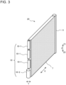
- the heat exchanger 20 includes a heat exchange module 7 and a refrigerant distributor 10 connected to one of end portions of the heat exchange module 7. Furthermore, as illustrated in Figs. 2 and 3 , the heat exchanger 20 further includes a gas header 11. The gas header 11 is connected to the other end portion of the heat exchange module 7. An arrow in Fig. 2 indicates a direction in which the refrigerant flows when the heat exchange module 7 operates as an evaporator. That is, when the heat exchange module 7 operates as an evaporator, the refrigerant flows from the refrigerant distributor 10 into the heat exchange module 7 and flows out toward the compressor 5 (see Fig. 1 ) via the gas header 11.
- the refrigerant flows in the opposite direction to the direction in which the refrigerant flows when the heat exchange module 7 operates as an evaporator. That is, when the heat exchange module 7 operates as a condenser, the refrigerant flows from the gas header 11 into each of the heat transfer pipes 70 of the heat exchange module 7, then joins together in the refrigerant distributor 10, and flows out therefrom toward the expansion valve 9 (see Fig. 1 ).
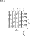
- the heat exchange module 7 includes a plurality of fins 71 arranged apart from each other in the X direction and heat transfer pipes 70 provided in such a manner as to penetrate the fins 71.
- the heat transfer pipes 70 are arranged apart from each other in the Z direction crossing the X direction. That is, the heat transfer pipes 70 extend in the X direction. Furthermore, the heat transfer pipes 70 are joined to the fins 71.
- the heat transfer pipes 70 are, for example, flat tubes. It should be noted that the heat transfer pipes 70 are not limited to the flat tubes but may be, for example, small heat transfer pipes that are smaller in inside diameter than common heat transfer pipes.
- each of the heat transfer pipes 70 is elongated to have a major axis and a minor axis.
- the minor axis of the heat transfer pipe 70 extends in the Z direction, and the major axis of the heat transfer pipe 70 extends in the Y direction. Since the heat transfer pipe 70 is elongated, the perimeter of the heat transfer pipe per cross section can be made longer than that of a circular tube. In this case, assume that the diameter of the circular tube in this case is equal to the length of the minor axis of the flat tube. In such a manner, the heat transfer pipe 70 is formed to be longer in perimeter than the circular tube. To that extent, the heat transfer pipe 70 is larger in heat transfer area than the circular tube.
- the heat transfer pipes 70 are porous flat tubes.
- the interior of each of the heat transfer pipes 70 is divided by interior columns 72 into smaller tubes that form a plurality of refrigerant flow passages 73 that are small in diameter.
- the circular tube is configured to have only one refrigerant flow passage that is large in diameter.
- Each of the heat transfer pipes 70 as illustrated in Fig. 5 can be segmented such that its length of contact between the refrigerant and the tube interior per cross section is more than double that of an unsegmented flat tube.
- the heat exchange efficiency is further improved.
- segmented heat transfer pipes for example, flat tubes
- it is possible to obtain some advantages for example, it is possible to reduce the amount of the refrigerant and improve the performance of the heat exchange module 7.
- Embodiment 1 in order to evenly distribute the refrigerant to the heat transfer pipes 70 and provide an optimum number of rows in the heat exchange module 7, a refrigerant distributor 10 obtained by combining two types of distributors having different configurations is used. This will be described in detail.
- the refrigerant distributor 10 is connected to one of end portions of the heat exchange module 7 in the X direction.
- the one end portion of the heat exchange module 7 in the X direction may be sometimes referred to as "first end portion”.
- the other end portion of the heat exchange module 7 in the X direction may be sometimes referred to as "second end portion”.
- the gas header 11 is connected to the second end portion of the heat exchange module 7.
- the refrigerant distributor 10 includes one or more distributors 10-1 and one communication header 10-2.
- Fig. 2 illustrates an example in which the refrigerant distributor 10 includes N distributors 10-1 and one communication header 10-2.
- the number of distributors 10-1 may be any number greater than or equal to 1.
- N is an arbitrary integer greater than or equal to 1.
- the N distributors 10-1 and the one communication header 10-2 are arranged side by side in the Z direction. Supposing that the Z direction is an up-down direction, the communication header 10-2 is provided under the distributors 10-1.
- M is the number of refrigerant streams into which the refrigerant is branched in each of the distributors 10-1 is M
- some of the heat transfer pipes 70 of the heat exchange module 7 (N ⁇ M of the total number of heat transfer pipes 70) are connected to the N distributors 10-1.
- some others (K) of the plurality of heat transfer pipes 70 of the heat exchange module 7 are connected to the communication header 10-2.
- the number of refrigerant streams into which the refrigerant is branched is M.
- M is not limited to 8. It suffices that M is an integer greater than or equal to 2. It should be noted, however, that M is a power of 2. Therefore, since the number of refrigerant streams into which the refrigerant is branched in each of the N distributors 10-1 is M, the number of heat transfer pipes 70 that are connected to all the distributors 10-1 is N ⁇ M as described above. On the other hand, the number of refrigerant streams into which the refrigerant is branched in the communication header 10-2 is K.
- the number of heat transfer pipes 70 that are connected to the communication header is K.
- the total number of heat transfer pipes 70 of the heat exchange module 7 is N ⁇ M + K.
- the total number of heat transfer pipes 70 of the heat exchange module 7 may be sometimes referred to as "the number of paths in the heat exchange module 7" or "the number of rows in the heat exchange module 7".
- K is set to a value smaller than M. That is, in the case where M is 8, K is an arbitrary integer that falls within the range of 1 to 7. This will be described in detail.
- Fig. 6 is a sectional view illustrating an example of the configuration of a communication header provided in the heat exchanger according to Embodiment 1.
- the communication header 10-2 is formed in the shape of a cylinder having a bottom and extending in the Z direction.
- the communication header 10-2 has an upper portion and a lower end portion that are closed.
- the communication header 10-2 includes one first opening 100 and a plurality of second openings 101 in its side surface. The first opening 100 faces the second openings 101.
- the number of the second openings 101 corresponds to the number of refrigerant streams into which the refrigerant is branched in the communication header 10-2, that is, the number of refrigerant streams into which the refrigerant is branched in the communication header 10-2.
- the number of refrigerant streams into which the refrigerant is branched in the communication header 10-2 is K.
- the number of the second openings 101 is K.
- the K second openings 101 of the communication header 10-2 are connected with the K ones of the heat transfer pipes 70 of the heat exchange module 7.
- the second openings 101 serve as heat transfer pipe insertion spaces.
- the communication header 10-2 includes a communication space 102 therein.
- the communication space 102 extends in the Z direction.
- the communication space 102 communicates with the first opening 100 and communicates with all the second openings 101. Refrigerant that flows into the communication space 102 through the first opening 100 flows out to the heat transfer pipes 70 of the heat exchange module 7 through the K second openings 101.
- the communication header 10-2 operates as a distributor configured to cause the refrigerant that flows thereinto to branch into K refrigerant streams and cause the refrigerant streams to flow out to the heat transfer pipes 70 of the heat exchange module 7.
- the gas header 11 has a similar configuration to that of the communication header 10-2 as illustrated in Fig. 6 . That is, the gas header 11 is formed in the shape of a cylinder having a bottom and extending in the Z direction. The gas header 11 has an upper end portion and a lower end portion that are closed. Furthermore, the gas header 11 includes one first opening and a plurality of second openings that are formed in its side surfaces. The gas header includes a communication space therein. The communication space extends in the Z direction. The communication space communicates with the first opening and all the second openings. The refrigerant that flows into the communication space through the first opening flows out through the second openings 101 to connection pipes connected to the gas header 11.
- Fig. 7 is an exploded perspective view illustrating an example of the configuration of a distributor provided in the heat exchanger according to Embodiment 1.
- each of the distributors 10-1 includes a stack type header including, for example, one first opening 103, a plurality of second openings 104, and distribution flow passages 105 connecting the first opening 103 with the second openings 104.
- the distribution flow passages 105 include a first flow passage 105a and two first branch flow passages 105b into which the first flow passage 105a branches. Furthermore, the distribution flow passages 105 include a second flow passage 105c connected with a first branch flow passage 105b and two second branch flow passages 105d into which the second flow passage 105c branches. Furthermore, the distribution flow passages 105 include a third flow passage 105e connected with a second branch flow passage 105d and two third branch flow passages 105f into which the third flow passage 105e branches.
- the above description concerning Embodiment 1 is made with reference to the case where the number M of times the refrigerant is branched is 8, but it is not limiting. That is, the distributor 10-1 is a two-branch distributor in which the number of refrigerant streams into which the refrigerant is branched is a power of 2.
- the distributor 10-1 includes a first plate-like element 106, a second plate-like element 107, and a third plate-like element 108.
- the first plate-like element 106, the second plate-like element 107, and the third plate-like element 108 basically have the same shape and the shape size in outer perimeter, and are each formed in the shape of a rectangular plate that is vertically long. Accordingly, the longitudinal direction of each of the first plate-like element 106, the second plate-like element 107, and the third plate-like element 108 is the Z direction.
- the distributor 10-1 is formed by a stack of one or more plate-like elements each having a flow passage that causes the refrigerant to branch into two refrigerant streams.
- the distributor 10-1 further includes a communication wall 109 provided between the first plate-like element 106 and the second plate-like element 107 and a collision wall 110 provided between the second plate-like element 107 and the third plate-like element 108.
- the communication wall 109 and the collision wall 110 are formed in the shape of a rectangular plate that is vertically long.
- the communication wall 109 and the collision wall 110 basically have the same plate shape and the same size in perimeter as those of the first plate-like element 106, the second plate-like element 107, and the third plate-like element 108. Therefore, the longitudinal direction of each of the first plate-like element 106, the second plate-like element 107, and the third plate-like element 108 is the Z direction.
- the first plate-like element 106, the communication wall 109, the second plate-like element 107, the collision wall 110, and the third plate-like element 108 are stacked together in this order, thereby forming the stack type header included in the distributor 10-1.
- the first plate-like element 106 is provided with the first opening 103.
- the first opening 103 is, for example, an inlet tube.
- the first opening 103 is provided in central part of the first plate-like element 106 in the longitudinal direction of the first plate-like element 106 that is vertically long.
- the first plate-like element 106 is provided with two second flow passages 105c.
- One of the two second flow passages 105c is located above the first opening 103, and the other of the two second flow passages 105c is located below the first opening 103.
- Each of the second flow passages 105c is formed in the shape of a projection.
- the second flow passage 105c basically extends substantially in the Z direction, the second flow passage 105c is inclined at a certain angle relative to the Z direction.
- the second flow passage 105c projects in a direction away from the communication wall 109.
- the second flow passage 105c has a groove therein.
- a pair of third flow passages 105e are provided on both sides of the second flow passage 105c in the Y direction.
- Each of the third flow passages 105e is formed in the shape of a projection.
- the third flow passage 105e basically extends substantially in the Z direction, the third flow passage 105e is inclined at a certain angle relative to the Z direction.
- the third flow passage 105e is provided to extend parallel to the second flow passage 105c.
- the third flow passage 105e projects in a direction away from the communication wall 109.
- the third flow passage 105e has a groove therein.
- An end portion (hereinafter "first end portion") of the third flow passage 105e is located at the same level as an end portion (hereinafter "first end portion") of the second flow passage 105c.
- the communication wall 109 has a plurality of through holes formed therethrough.
- the through holes include first through holes 109a, second through holes 109b, and third through holes 109c.
- the first through holes 109a, the second through holes 109b, and the third through holes 109c extend through the communication wall 109.
- the first opening 103 and second end portions of the second flow passages 105c communicate with each other via three first through holes 109a of the above through holes, the three first through holes 109a being provided in central part of the communication wall 109 in the longitudinal direction of the communication wall 109 and being arranged in the Y direction.
- each of the second flow passages 105c is located on the opposite side of a side where the first end portion of that second flow passage 105c is located, in the longitudinal direction. Furthermore, three second through holes 109b arranged in the Y direction are located above the first through holes 109a, and other three second through holes 109b arranged in the Y direction are located below the first through holes 109a. The first end portions of the second flow passages 105c and first end portions of the third flow passages 105e communicate with each other via the second through holes 109b. Of the third through holes 109c, one third through hole 109c is located above the second through holes 109b, and another one third through hole 109c is located below the second through holes 109b.
- the third through holes 109c communicate with second end portions of the third flow passages 105e.
- the second end portion of each of the third flow passages 105e is located on the opposite side of a side where the first end portion of the third flow passage 105e is located, in the longitudinal direction.
- the second plate-like element 107 includes a plurality of slits provided to cause the refrigerant to branch into two refrigerant streams.
- the slits include a first slit 107a, second slits 107b, and third slits 107c.
- the first slit 107a, the second slits 107b, and the third slits 107c extend through the second plate-like element 107.
- the first opening 103 and the second end portions of the second flow passages 105c communicate with each other via an I-shaped first slit 107a of the above slits that is formed in central part of the second plate-like element 107 in the longitudinal direction of the second plate-like element 107.
- the longitudinal direction of the first slit 107a is the Y direction.
- the refrigerant that flows from the first opening 103 passes through the first flow passage 105a and flows into the first slit 107a of the second plate-like element 107.
- the refrigerant that passes through the first slit 107a branches into two refrigerant streams by colliding with the collision wall 110. Then, the refrigerant streams pass through the first branch flow passages 105b and flow into the second end portions of the second flow passages 105c of the first plate-like element 106.
- the second slits 107b include an I-shaped second slit 107b formed above the I-shaped first slit 107a of the second plate-like element 107 and an I-shaped second slit 107b formed below the I-shaped first slit 107a of the second plate-like element 107.
- the longitudinal direction of each of the second slits 107b is the Y direction.
- the refrigerant that flows through the second flow passage 105c flows out from the first end portion of the second flow passage 105c. Then, the refrigerant passes through a second slit 107b of the second plate-like element 107 and collides with the collision wall 110 to branch into two refrigerant streams. Then, the refrigerant streams pass through the second branch flow passages 105d and flow into the first end portions of the third flow passages 105e of the first plate-like element 106.
- the third slits 107c include S-shaped third slits 107c provided above and below the I-shaped second slits 107b of the second plate-like element 107.
- the refrigerant that flows through the third flow passage 105e flows out from the second end portion of the third flow passage 105e. Then, the refrigerant flows into central portion of the S-shaped third slit 107c of the second plate-like element 107.
- the refrigerant that passes through the central portion of the third slit 107c collides with the collision wall 110 to branch into two refrigerant streams. Then, the two refrigerant streams flow out from both ends of the S-shaped third slit 107c in the Z direction.
- the collision wall 110 has a plurality of I-shaped slits 110a formed therein.
- the longitudinal direction of the slits 110a is the Y direction. These slits 110a are provided in association with the locations of the heat transfer pipes 70.
- the third plate-like element 108 has the second openings 104.
- the second openings 104 are I-shaped slits.
- the longitudinal direction of each of the second openings 104 is the Y direction.
- These second openings 104 are arranged in association with the locations of the heat transfer pipes 70.
- the second openings 104 serve as heat transfer pipe insertion spaces into which the heat transfer pipes 70 are inserted.
- the refrigerant that flows out from both ends of an S-shaped third slit 107c of the second plate-like element 107 in the Z direction passes through slits 110a of the collision wall 110 and second openings 104 of the third plate-like element 108 along the third branch flow passages 105f and flows into heat transfer pipes 70.
- the distributor 10-1 is not limited to the stack type header as illustrated in Fig. 7 .
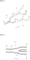
- Fig. 8 is a perspective view illustrating another example of the configuration of a distributor provided in the heat exchanger according to Embodiment 1.
- Fig. 9 is a sectional view illustrating the configuration of the distributor as illustrated in Fig. 8 .
- each of the distributors 10-1 may be a Y-joint that is Y-shaped and that has a flow passage provided to cause the refrigerant to branch into two refrigerant streams.
- the distributor 10-1 includes one first opening 103 and a plurality of second openings 104.
- the distributor 10-1 has a flow passage 120 through which the refrigerant flows and that is formed in the distributor 10-1.
- the flow passage 120 branches into two branches at a branch point between the first opening 103 and the second openings 104.
- the branch point serves as a collision wall 121.
- the refrigerant that flows from the first opening 103 branches into two refrigerant streams by colliding with the collision wall 121.
- a plurality of other Y-joints are prepared and coupled to the distributor 10-1 in the X direction, whereby a two-branch distributor can be formed in which the number of refrigerant streams into which the refrigerant is branched is a power of 2. That is, the number of refrigerant streams into which the refrigerant is branched is 4 when two rows of Y-joints are coupled in the X direction, and the number of refrigerant streams into which the refrigerant is branched is 8 when three rows of Y-joints are coupled in the X direction.
- each of the distributors 10-1 is a two-branch distributor in which branching of the refrigerant into two refrigerant streams is repeated a plurality of times and the number M of refrigerant streams into which the refrigerant is branched is a power of 2.
- the first opening 103 of each of the distributors 10-1 may be sometimes referred to "first inlet”, and the second openings 104 of each of the distributors 10-1 may be sometimes referred to as "first outlets”.
- the first opening 100 of the communication header 10-2 may be sometimes referred to as “second inlet”, and the second openings 101 of the communication header 10-2 may be sometimes referred to as "second outlets”.
- K is set to a value smaller than M. If the refrigerant distributor 10 does not include a communication header 10-2 and includes the distributors 10-1 only, the number of rows in the heat exchange module 7 is increased in increment of M rows depending on the number (N) of distributors 10-1. In this case, it is hard to use the heat exchange module 7 having an optimum number of rows, because the optimum number of rows in the heat exchange module 7 is not necessarily a multiple of M
- Fig. 10 is a graph indicating a relationship between the number of paths in the heat exchange module of the heat exchanger according to Embodiment 1 and an annual performance factor (APF).
- the horizontal axis represents the number of paths in the heat exchange module
- the vertical axis represents the annual performance factor APF.
- the annual performance factor APF is an index based on JIS C9612 that represents cooling and heating capacity per kilowatt of electricity that is consumed when an air-conditioning apparatus is in operation under certain conditions (set forth in JIS C9612). The higher the value of value of the annual performance factor APF, the higher the energy-saving performance. It can be seen from the graph of Fig.
- the value of the annual performance factor APF changes depending on the number of paths in the heat exchange module 7.
- the value of the annual performance factor APF is the highest when the number of paths in the heat exchange module 7 is N ⁇ M + K.
- the annual performance factor APF is the lowest value
- the number of paths in the heat exchange module 7 is (N + 1) ⁇ M
- the annual performance factor APF is the second lowest, for the following reason.
- the optimum number of rows is N ⁇ M + K.
- the number of paths in the heat exchange module 7 is insufficient.
- a pressure loss in the pipes increases because of an increase in the flow velocity of refrigerant, and as a result, the performance of the evaporator performance deteriorates.
- the number of paths is (N + 1) ⁇ M
- the number of rows in the heat exchange module 7 increases, and the thermal conductivity decreases because of a decrease in the flow velocity of the refrigerant, thereby deteriorating the performance of the condenser.
- the refrigerant distributor 10 includes only the distributors 10-1 without including the communication header 10-2, the number of rows in the heat exchange module 7 is increased in increment of M rows according to the number (N) of the distributors 10-1.
- the optimum number of paths cannot be provided.
- the number of paths in the communication header 10-2 is K and K is set to a value smaller than M, whereby it is possible to easily provide the optimum number of paths in the heat exchange module 7 by appropriately selecting the value of K in the range of 1 to 7.
- Fig. 11 is a block diagram illustrating a configuration of a heat exchanger of a comparative example.
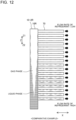
- Fig. 12 is an explanatory view for the flow rates of refrigerant through heat transfer pipes and the communication header under conditions where the flow rate of flow of refrigerant in the heat exchanger of the comparative example is small.
- Fig. 13 is an explanatory view for a refrigerant distribution state under conditions where the flow amount of circulation of the refrigerant in an air-conditioning apparatus of the comparative example is small.
- Fig. 14 is an explanatory view for a refrigerant distribution view under conditions where the flow amount of circulation of the refrigerant in the air-conditioning apparatus of the comparative example is large.
- the heat exchanger of the comparative example includes a heat exchange module 7R in which the number of rows is L, a refrigerant distributor 10R, and a gas header 11R.
- the refrigerant distributor 10R includes only a communication header 10-2R in which the number of refrigerant streams into which the refrigerant branches is L. As the number of time the refrigerant branches in the communication header 10-2R, it is possible to select an arbitrary number.
- Fig. 12 illustrates the flow rates of the refrigerant in the communication header 10-2R and heat transfer pipes 70 in the comparative example under conditions where the flow rate of the refrigerant is small.
- a pressure loss in the communication header 10-2R is caused mainly by a flow resistance due to gravity.
- a pressure loss in each of the heat transfer pipes 70 is caused mainly by a frictional resistance. Therefore, a lower resistance due to is applied on refrigerant that flows through the paths of heat transfer pipes 70 connected to lower part of the communication header 10-2R than on refrigerant that flows through the paths of heat transfer pipes 70 connected to upper part of the communication header 10-2R. Since a lower resistance is applied, the flow rate of the refrigerant that flows through the path of a heat transfer pipe 70 connected to the lower part of the communication header 10-2R tends to increase accordingly.
- the flow of refrigerant among the heat transfer pipes 70 may be uneven.
- the flow velocity of the refrigerant that flows into the communication header 10-2R is relatively low. Therefore, under the influence of gravity, a liquid-phase component of the refrigerant that is higher in specific gravity flows downward in the communication header 10-2R, and a gas-phase component of the refrigerant that is lower in specific gravity flows upward in the communication header 10-2R. Thus, it is hard to cause the liquid-phase component to reach upper ones of the plurality of heat transfer pipes 70.
- the amount of passage of the refrigerant in the heat transfer pipes 70 varies depending on the level in the Z direction, that is, the amount of passage of the refrigerant is uneven, whereby the flow of the refrigerant may be uneven.
- the refrigerant that flows out from the other end of the heat transfer pipe 70 becomes too high in degree of superheat.
- the refrigerant is flowing through the heat transfer pipe 70, it cannot not change in phase, and thus cannot achieve a sufficient heat-exchange performance.
- the refrigerant that flows out from the other end of the heat transfer pipe 70 does not easily have a degree of superheat. Consequently, the refrigerant may reach the other end of the heat transfer pipe 70 without evaporating. Accordingly, in this case also, the refrigerant does not illustrate fully a heat-exchange performance. In such a manner, in the case where the flow of the refrigerant between the heat transfer pipes 70 is uneven, the refrigerant does not achieve a sufficient heat-exchange performance, thus deteriorating the air-conditioning performance of the air-conditioning apparatus decreases.
- Fig. 14 illustrates the case where the flow amount of circulation of the refrigerant is large.
- the flow of the refrigerant between the heat transfer pipes 70 may also be uneven.
- the flow velocity of refrigerant that flows into the communication header 10-2R is relatively high. Therefore, in the case where the flow amount of circulation of the refrigerant is large, a liquid-phase component of refrigerant that forcibly passes through an inlet of the communication header 10-2R tends to collect at a higher position in the communication header 10-2R, because the liquid-phase component is high in specific gravity.
- Embodiment 1 as the distributors 10-1, two-branch distributors are used. In each of the two-branch distributors, branching of the refrigerant into two refrigerant streams is repeated a number of times.
- the number M of refrigerant streams into which the refrigerant branches in each of the distributors 10-1 is 8. If the refrigerant is branched into eight refrigerant streams at once, such an uneven flow of refrigerant as described above is produced, and it is therefore hard to evenly distribute the refrigerant to the heat transfer pipes 70. Therefore, in Embodiment 1, the two-branch distributors are used in order that the refrigerant be distributed as evenly as possible.
- Embodiment 1 uses the refrigerant distributor 10 that is a combination of two types of distributors.
- the heat transfer pipes segmented heat transfer pipes such as flat tubes, it is possible to provide the heat exchange module 7 that evenly distributes the refrigerant to the heat transfer pipes 70 and that has an optimum number of rows for maximizing the heat exchange performance.
- Embodiment 1 ensures the degree of freedom in the design of the heat exchange module 7 by using in combination with the distributors 10-1, the communication header 10-2 in which the number K of refrigerant streams into which the refrigerant branches can be freely selected. As a result, it is possible to obtain the heat exchange module 7 that has an optimum number of paths for maximizing the annual performance factor APF. In such a manner, in Embodiment 1, it is possible to improve the heat exchanging performance by using the distributors 10-1 in each of which the number of refrigerant streams into which the refrigerant branches is M in combination with the communication header 10-2 in which the number of refrigerant streams into which the refrigerant branches is K.
- the main heat exchange module 7A has the same configuration as the heat exchange module 7 of Embodiment 1. Therefore, the refrigerant distributor 10 and the gas header 11 are connected to respective ends of the main heat exchange module 7A in the X direction.
- the auxiliary heat exchange module 7B is provided under the main heat exchange module 7A.
- the auxiliary heat exchange module 7B serves as an aid for the main heat exchange module 7A.
- the heat exchange module 7 operates as a condenser
- the refrigerant flows through the main heat exchange module 7A and the auxiliary heat exchange module 7B in this order. Accordingly, the refrigerant is subjected to heat exchange in the main heat exchange module 7A to change into low-temperature refrigerant, and the low-temperature refrigerant is then subjected to heat exchange in the auxiliary heat exchange module 7B and is thus cooled. It is therefore possible to obtain a sufficient degree of subcooling.
- the auxiliary heat exchange module 7B may be activated only when needed.
- an on-off valve (not illustrated) is provided in advance and performs its switching operation to allow the refrigerant to flow into the auxiliary heat exchange module 7B or inhibit the refrigerant from flowing into the auxiliary heat exchange module 7B.
- the configuration may be set that only the main heat exchange module 7A operates first during heating and during cooling, and in the case where the output of the heat exchanger 20 needs to be increased, the auxiliary heat exchange module 7B operates in conjunction with the main heat exchange module 7A.
- the timing at which the auxiliary heat exchange module 7B is to be activated may be appropriately set depending on the intended use of the air-conditioning apparatus 1.
- the heat exchange module 7 may include a main heat exchange module 7A and an auxiliary heat exchange module 7B as in the modification as illustrated in Figs. 15 and 16 . Furthermore, needless to say, the modification can obtain similar advantages to those of Embodiment 1.
- a heat exchanger according to Embodiment 2 will be described with reference to Figs. 17 to 21 .
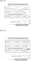
- Fig. 17 is a schematic view illustrating a configuration of a heat exchanger according to Embodiment 2.
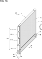
- Fig. 18 is a perspective view illustrating the configuration of the heat exchanger according to Embodiment 2.
- the heat exchanger according to Embodiment 2 operates as an evaporator.
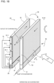
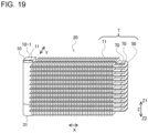
- Fig. 19 is a perspective view illustrating examples of couplings that connect heat transfer pipes of a windward heat exchange module and heat transfer pipes of a leeward heat exchange module in the heat exchanger according to Embodiment 2.
- Fig. 20 is a configuration diagram illustrating the configuration of the heat exchanger according to Embodiment 2.
- Fig. 21 is a perspective view illustrating the configuration of the heat exchanger according to Embodiment 2.
- the heat exchanger according to Embodiment 2 operates as a condenser.
- Embodiment 2 in each of the rows, associated two of the heat transfer pipes 70 of the heat exchange module 7 are arranged on a windward side and a leeward side in the flow direction of air.
- the flow direction of air is the Y direction that crosses the X direction and the Z direction, as indicated by an outlined arrow in each of Figs. 18 and 21 .
- the lower right is windward
- the upper left is leeward.
- the heat exchange module 7 includes a windward heat exchange module 7-1 including windward heat transfer pipe rows on the windward side and a leeward heat exchange module 7-2 including leeward heat transfer pipe rows on the leeward side.
- the above air is supplied by the air-sending fan 8 (see 8a and 8b in Fig. 1 ).
- the windward heat exchange module 7-1 includes a windward main heat exchange module 7C and a windward auxiliary heat exchange module 7D.
- the windward main heat exchange module 7C has a first number of rows.
- the first number of rows is, for example, K + N ⁇ 2 X .
- the windward auxiliary heat exchange module 7D is provided alongside of the windward main heat exchange module 7C in the Z direction. Specifically, the windward auxiliary heat exchange module 7D is located under the windward main heat exchange module 7C.
- the windward auxiliary heat exchange module 7D has a second number of rows that is smaller than the first number of rows. Where the total number of rows of the windward heat exchange module 7-1 is L, the second number of rows is L - (K + N ⁇ 2 X ).
- the gas header 11 is connected to one end of the windward main heat exchange module 7C.
- a third refrigerant distributor 31 is connected to one end of the windward auxiliary heat exchange module 7D.
- the third refrigerant distributor 31 is a distributor for use in an auxiliary heat exchange module.
- the third refrigerant distributor 31 has a similar configuration to that of, for example, the gas header 11.
- the leeward heat exchange module 7-2 includes a leeward main heat exchange module 7E and a leeward auxiliary heat exchange module 7F.
- the leeward main heat exchange module 7E has a first number of rows. The first number of rows is, for example, K + N ⁇ 2 X .
- the leeward auxiliary heat exchange module 7F is provided alongside with the leeward main heat exchange module 7E in the Z direction. Specifically, the leeward auxiliary heat exchange module 7F is located under the leeward main heat exchange module 7E.
- the leeward auxiliary heat exchange module 7F has a second number of rows that is smaller than the first number of rows. Where the total number of rows of the leeward heat exchange module 7-2 is L, the second number of rows is L - (K + N ⁇ 2 X ).
- first number of rows and the second number of rows in the windward heat exchange module 7-1 may be the same as or different from the first number of rows and the second number of rows in the leeward heat exchange module 7-2.
- the following description is made by referring to by way of example the case where the first number of rows and the second number of rows in the windward heat exchange module 7-1 are the same as the first number of rows and the second number of rows in the leeward heat exchange module 7-2.
- heat transfer pipes 70 included in the windward heat transfer pipe rows of the windward heat exchange module 7-1 are connected to respective heat transfer pipes 70 included in the leeward heat transfer pipe rows of the leeward heat exchange module 7-2 by respective couplings 50.
- Each of the couplings 50 is connected to ends (i.e. the other ends) of associated two of the connected heat transfer pipes, the ends being opposite, in the X direction, to those ends of the above associated two heat transfer pipes to which the gas header 11 and the refrigerant distributor 10 are connected.
- each of the couplings 50 is, for example, a U-shaped tube.
- the coupling 50 is not limited to the U-shaped tube but may be formed in the shape of a box having a communication space therein.
- the refrigerant flows as indicated by arrows (1), (2), (3), and (4) in this order in Fig. 17 . That is, when the heat exchange module 7 operates as an evaporator, the refrigerant flows through the windward auxiliary heat exchange module 7D, the leeward auxiliary heat exchange module 7F, the leeward main heat exchange module 7E, and the windward main heat exchange module 7C in this order.
- the heat exchange module 7 when the heat exchange module 7 operates as a condenser, the refrigerant flows as indicated by arrows (1), (2), (3), and (4) in this order in Fig. 20 . That is, when the heat exchange module 7 operates as a condenser, the refrigerant flows through the windward main heat exchange module 7C, the leeward main heat exchange module 7E, the leeward auxiliary heat exchange module 7F, and then the windward auxiliary heat exchange module 7D in this order.
- Embodiment 2 as illustrated in Fig. 18 , when the heat exchange module 7 operates as an evaporator, the flow of the refrigerant though the windward main heat exchange module 7C and the leeward main heat exchange module 7E and the flow of air are opposite to each other.
- the heat exchange module 7 when the heat exchange module 7 operates as a condenser, the flow of the refrigerant though the windward main heat exchange module 7C and the leeward main heat exchange module 7E and the flow of the air are parallel to each other.
- Embodiment 2 a refrigerant distributor 10 including distributors 10-1 and a communication header 10-2 is also used as in Embodiment 2, and it is therefore possible to obtain similar advantages to those of Embodiment 1. That is, in Embodiment 2, it is also possible to obtain a heat exchange module 7 having an optimum number of rows for maximizing the annual performance factor APF of the air-conditioning apparatus 1, while evenly distributing the refrigerant.
- Embodiment 2 when the heat exchange module 7 operates as a condenser, the refrigerant flows through the windward main heat exchange module 7C, the leeward main heat exchange module 7E, the leeward auxiliary heat exchange module 7F, and then the windward auxiliary heat exchange module 7D in this order, as illustrated in Fig. 20 .
- the outdoor heat exchange module 7a of the outdoor heat exchanger 20a as illustrated in Fig. 1 operates as a condenser
- the outdoor heat exchange module 7a may be defrosted.
- the high-temperature gas refrigerant discharged from the compressor 5 flows from the windward side, on which the amount of frost is larger. It is therefore possible to efficiently melt frost, thereby improving the heating performance at a low temperature.
- a heat exchanger according to Embodiment 3 will be described with reference to Figs. 22 to 25 .
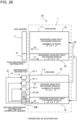
- Fig. 22 is a configuration diagram schematically illustrating a configuration of a heat exchanger according to Embodiment 3.
- Fig. 23 is a perspective view illustrating the configuration of the heat exchanger according to Embodiment 3.
- the heat exchanger according to Embodiment 3 operates as an evaporator.
- Fig. 24 is a configuration diagram schematically illustrating the configuration of the heat exchanger according to Embodiment 3.
- Fig. 25 is a perspective view illustrating the configuration of the heat exchanger according to Embodiment 3.
- the heat exchanger according to Embodiment 3 operates as a condenser.
- Embodiment 3 in each of the rows, associated two of the heat transfer pipes 70 of the heat exchange module 7 are arranged on a windward side and a leeward side in the flow direction of air, as in Embodiment 2.
- the flow direction of air is the Y direction that crosses the X direction and the Z direction as indicated by an outlined arrow in Figs. 23 and 25 .
- the upper left is windward and the lower right is leeward.
- the flow direction of air in Figs. 23 and 25 is opposite to that in Figs. 18 and 21 relating to Embodiment 2.
- the windward side and the leeward side of Figs. 23 and 25 are opposite to the windward side and the leeward side of Figs. 18 and 21 relating to Embodiment 2.
- the heat exchange module 7 includes a windward heat exchange module 7-1 including windward heat transfer pipe rows on the windward side and a leeward heat exchange module 7-2 including leeward heat transfer pipe rows on the leeward side.
- the leeward heat exchange module 7-2 basically has the same configuration as the modification of Embodiment 1. It will be described in detail.
- the windward heat exchange module 7-1 includes a windward main heat exchange module 7G and a windward auxiliary heat exchange module 7H.
- the windward main heat exchange module 7G includes a first number of rows. The first number of rows is, for example, K + N ⁇ 2 X .
- the windward auxiliary heat exchange module 7H is provided alongside with the windward main heat exchange module 7G in the Z direction. Specifically, the windward auxiliary heat exchange module 7H is located under the windward main heat exchange module 7G.
- the windward auxiliary heat exchange module 7H includes a second number of rows that is smaller than the first number of rows. Where the total number of rows of the windward heat exchange module 7-1 is L, the second number of rows is L - (K + N ⁇ 2 X ).
- a refrigerant distributor 10 is connected to one end of the windward main heat exchange module 7G.
- the refrigerant distributor 10 has the same configuration as the refrigerant distributor 10 as illustrated in Embodiment 1.
- a second refrigerant distributor 30A is connected to one end of the windward auxiliary heat exchange module 7H.
- the second refrigerant distributor 30A is a distributor for use in an auxiliary heat exchange module.
- the second refrigerant distributor 30A is, for example, a communication header.
- the leeward heat exchange module 7-2 includes a leeward main heat exchange module 7I and a leeward auxiliary heat exchange module 7J.
- the leeward main heat exchange module 7I has a first number of rows. The first number of rows is, for example, K + N ⁇ 2 X .
- the leeward auxiliary heat exchange module 7J is provided alongside with the leeward main heat exchange module 7I in the Z direction. Specifically, the leeward auxiliary heat exchange module 7J is located under the leeward main heat exchange module 7I.
- the leeward auxiliary heat exchange module 7J has a second number of rows that is smaller than the first number of rows. Where the total number of rows of the leeward heat exchange module 7-2 is L, the second number of rows is L - (K + N ⁇ 2 X ).
- the gas header 11 is connected to one end of the leeward main heat exchange module 7I.
- a third refrigerant distributor 31A is connected to one end of the leeward auxiliary heat exchange module 7J.
- the third refrigerant distributor 31A is a distributor for use in an auxiliary heat exchange module.
- the third refrigerant distributor 31 is, for example, an interflow header.
- the interflow header may have the same configuration as the second refrigerant distributor 30 as illustrated in Embodiment 2.
- the heat transfer pipes 70 included in the windward heat transfer pipe rows of the windward heat exchange module 7-1 are connected to respective heat transfer pipes 70 included in the leeward heat transfer pipe rows of the leeward heat exchange module 7-2 by respective couplings 50.
- a description concerning the couplings 50 will be omitted.
- the refrigerant flows as indicated by arrows (1), (2), (3), and (4) in Fig. 22 . That is, when the heat exchange module 7 operates as an evaporator, the refrigerant flows through the windward auxiliary heat exchange module 7H, the leeward auxiliary heat exchange module 7J, the windward main heat exchange module 7G, and the leeward main heat exchange module 7I in this order.
- the refrigerant flows as indicated by arrows (1), (2), (3), and (4) in Fig. 24 . That is, when the heat exchange module 7 operates as a condenser, the refrigerant flows through the leeward main heat exchange module 7I, the windward main heat exchange module 7G, the leeward auxiliary heat exchange module 7J, and the windward auxiliary heat exchange module 7H in this order.
- Embodiment 3 as illustrated in Fig. 23 , when the heat exchange module 7 operates as an evaporator, the flow of the refrigerant and the flow of the air are parallel to each other.
- Fig. 25 when the heat exchange module 7 operates as a condenser, the flow of the refrigerant and the flow of the air are opposite to each other.
- Embodiment 3 a refrigerant distributor 10 that includes y distributors 10-1 and a communication header 10-2 is used as in Embodiments 1 and 2. It is therefore possible to obtain the same advantages as in Embodiments 1 and 2. That is, in Embodiment 3, it is possible to obtain the heat exchange module 7 that includes an optimum number of rows for maximizing the annual performance factor APF of the air-conditioning apparatus 1, while evenly distributing the refrigerant.
- Embodiment 3 when the heat exchange module 7 operates as a condenser, the refrigerant flows through the leeward main heat exchange module 7I, the windward main heat exchange module 7G, the leeward auxiliary heat exchange module 7J, and the windward auxiliary heat exchange module 7H in this order.
- the outdoor heat exchange module 7a of the outdoor heat exchanger 20a of Fig. 1 operates as a condenser, the flow direction of the refrigerant flows is opposite to the flow direction of air. It is therefore possible to ensure a great temperature difference between the air and the refrigerant, thereby improving the heat exchanging performance.
- a heat exchanger according to Embodiment 4 will be described with reference to Figs. 26 to 31 .
- Fig. 26 is a configuration diagram schematically illustrating a configuration of a heat exchanger according to Embodiment 4.
- Fig. 27 is a perspective view schematically illustrating the configuration of the heat exchanger according to Embodiment 4.
- Figs. 26 and 27 illustrate the case where the heat exchanger according to Embodiment 4 operates as an evaporator.
- Fig. 30 is an explanatory diagram for describing the case where stagnation of refrigerant occurs in a common heat exchanger.
- a liquid pipe 91 is a refrigerant distributor that includes a communication header
- a gas pipe 90 is a gas header.
- a heat transfer pipe 92 is connected to the gas pipe 90, and a connection pipe 93 is connected to the liquid pipe 91.
- Fig. 30 will be described in detail later.
- the communication header 10-2A and the second refrigerant distributor 30B are formed integral with each other.
- the second refrigerant distributor 30B is an interflow header.
- the interflow header that is the second refrigerant distributor 30B
- its internal space is divided by first partition plates 30Bb into a plurality of sub-internal spaces 30Ba in association with heat transfer pipes 70 that are connected to the interflow header.
- the uppermost one of the sub-internal spaces 30Ba of the second refrigerant distributor 30B and the internal space of the communication header 10-2A are divided from each other by a second partition plate 60.
- the second partition plate 60 has a through hole 61 that extends through the second partition plate 60. Therefore, of the sub-internal spaces 30Ba, the sub-internal space 30Ba located at the highest position, that is, the above uppermost sub-inter space 30Ba, communicates with the internal space of the communication header 10-2A through the through hole 61.
- connection pipe 93 connected to the liquid pipe 91 is located at a higher position than that as illustrated in Fig. 30, (a) , and as a result, stagnation of the refrigerant may occur.
- the uppermost sub-internal space 30Ba and the internal space of the communication header 10-2A communicate with each other through the through hole 61. It is therefore possible to reduce occurrence of stagnation of the refrigerant.
- Embodiment 4 a refrigerant distributor 10 that includes distributors 10-1 and a communication header 10-2 is also used as in Embodiments 1 to 3. It is therefore possible to obtain similar advantages to those of Embodiments 1 to 3. That is, in Embodiment 4, it is possible to obtain a heat exchange module 7 having an optimum number of rows for maximizing the annual performance factor APF of the air-conditioning apparatus 1, while evenly distributing the refrigerant.
- Embodiment 4 it is possible to reduce the number of connection pipes 51 that connect the second refrigerant distributor 30B connected to the leeward auxiliary heat exchange module 7F and the refrigerant distributor 10 connected to the leeward main heat exchange module 7E. Accordingly, it is possible to increase the size of the heat exchange module 7, especially the heat transfer area of the heat exchange module 7, without changing the size of the housing the heat exchanger 20. As a result, the heat exchanging performance of the heat exchange module 7 can be improved.
- the heat transfer pipes 70 are flat tubes, but the heat transfer pipes 70 are not limited to the flat tubes.
- the heat transfer pipes 70 may be, for example, circular tubes.
- the refrigerant distributor of the heat exchanger also includes one or more distributors each including a collision wall therein and each configured to cause the refrigerant to be distributed because of collision of the refrigerant with the collision wall, and a communication header configured to cause the refrigerant to be distributed via a communication space.
- the number K of refrigerant streams into which the communication header causes the refrigerant to branch is set to a value smaller than the number M of refrigerant streams into which each of the one or more distributors causes the refrigerant to branch.
- one or more distributors each configured to more easily evenly distribute the refrigerant are used.
- the heat exchanger can evenly distribute the refrigerant as a whole.
- a communication header configured to cause the refrigerant to branch into the number K of refrigerant streams that is smaller than the number M is used in combination with the one or more distributors. Therefore, it is possible to freely select the number of rows in the heat exchanger, and thus design the heat exchanger such that the heat exchanger has an optimum number of rows for maximizing the performance of the heat exchanger.
Landscapes
- Engineering & Computer Science (AREA)
- Physics & Mathematics (AREA)
- Thermal Sciences (AREA)
- Mechanical Engineering (AREA)
- General Engineering & Computer Science (AREA)
- Heat-Exchange Devices With Radiators And Conduit Assemblies (AREA)
Abstract
Description
- The present disclosure relates to a heat exchanger including a refrigerant distributor and to an air-conditioning apparatus.
- In recent years, in air-conditioning apparatuses, heat transfer pipes for use in heat exchangers have been made narrower in order that the amount of refrigerant to be used be decreased and the heat exchangers be made to have a higher performance. In this connection, flat tubes have been used as the heat transfer pipes of the heat exchangers. However, in order to reduce the pressure loss of the refrigerant, it is necessary to increase the number of refrigerant streams into which the refrigerant is branched, because the flat tubes are small in hydraulic diameter.
- For example,
Patent Literature 1 discloses a heat exchanger employing a stack type distributor in which branching of the refrigerant into two refrigerant streams is repeated three times (23 = 8 refrigerant streams), in order to increase the number of refrigerant streams into which the refrigerant is branched. - In the heat exchanger described in
Patent Literature 1, a plurality of heat transfer pipes extending in a horizontal direction are arranged in a vertical direction. The stack type distributor is connected to one end of each of those heat transfer pipes. When the heat exchanger operates as an evaporator, refrigerant that flows through a refrigerant pipe flows into the stacked distributor and is distributed therefrom to the heat transfer pipes of the heat exchanger. In the heat transfer pipes, the refrigerant exchanges heat with air that is supplied by an air-sending device. - Patent Literature 1:
Japanese Patent No. 6214789 - As described above, in recent years, heat exchangers have been provided that include flat tubes in order that the amount of refrigerant to be used be reduced and the heat exchangers be made to have a higher performance. In such a heat exchanger, the number of refrigerant streams into which the refrigerant is branched may be increased in order to reduce the pressure loss of the refrigerant. However, in the case where the number of refrigerant streams into which the refrigerant is branched is increased, when the heat exchanger operates as an evaporator, it is hard to evenly distribute the refrigerant to the heat transfer pipes in the case where a communication header is used as a distributor. That is, since refrigerant that flows into the communication header in the above case is two-phase gas-liquid refrigerant, the refrigerant unevenly flows, for example, due to the effect of gravity such that, for example, liquid-phase refrigerant flows downward and gas-phase refrigerant flows upward. Accordingly, it is impossible to evenly distribute the refrigerant. In the case where it is impossible to evenly distribute the refrigerant, the performance of the heat exchanger easily deteriorates, especially during the heating operation.
- On the other hand, in the case of using a stack type distributor in which branching of the refrigerant into two refrigerant streams is repeated three times (23 = 8 refrigerant streams) as in the heat exchanger of
Patent Literature 1, an uneven flow of refrigerant is not produced, unlike the case of using the communication header. However, in the stack type distributor, branching of the refrigerant into two refrigerant streams is repeated three times, and the final number of refrigerant streams into which the refrigerant is branched is 8. Therefore, the number of rows in the heat exchanger changes in increments of eight rows (such as 8, 16, 24, ....) according to the number of stack type distributors to be arranged. Therefore, the "increments of eight rows" impose restrictions on the degrees of freedom in the design of the heat exchanger. Consequently, it is impossible to design the heat exchanger such that the heat exchanger has an optimum number of rows for maximizing the performance of the heat exchanger. - The present disclosure is applied to solve the above problem, and relates to a heat exchanger and an air-conditioning apparatus that have an optimum number of rows for maximizing the performance of the heat exchanger while achieving an even distribution of refrigerant to heat transfer pipes of the heat exchanger.
- A heat exchanger according to an embodiment of the present disclosure includes: a heat exchange module including a plurality of fins and a plurality of heat transfer pipes, and configured to cause heat exchange to be performed between refrigerant that flows in the heat exchange module and air that flows around the heat exchange module, the plurality of fins being arranged apart from each other in a first direction, the heat transfer pipes being provided to extend through the plurality of fins and arranged apart from each other in a second direction crossing the first direction; and a refrigerant distributor connected to an end portion of the heat exchange module in the first direction. The refrigerant distributor includes: one or more distributors including a first inlet and a plurality of first outlets with which some of the plurality of heat transfer pipes are connected, the one or more distributors each including a collision wall therein, and being configured to cause the refrigerant that flows from the first inlet into the one or more distributors to branch into refrigerant streams because of collision of the refrigerant with the collision wall, and cause each of the refrigerant streams to flow out from an associated one of the plurality of first outlets; and a communication header including a second inlet and a plurality of second outlets with which some others of the plurality of heat transfer pipes are connected, the communication header including a communication space therein, and being configured to cause the refrigerant that flows from the second inlet into the communication space to branch into refrigerant streams, and cause each of the refrigerant streams to flow out from an associated one of the plurality of second outlets. The number K of the refrigerant streams into which the refrigerant passes through the communication header to branch is smaller than the number M of refrigerant streams into which the refrigerant passes through the distributor to branch.
- An air-conditioning apparatus according to another embodiment of the present disclosure includes an outdoor unit and an indoor unit that are connected by a refrigerant pipe, whereby a refrigerant circuit is provided. The outdoor unit includes: a compressor configured to compress and discharge refrigerant; a four-way valve configured to switch a flow passage for the refrigerant between plural flow passages; an outdoor heat exchanger configured to cause heat exchange to be performed between outdoor air and the refrigerant; an outdoor fan configured to send the outdoor air to the outdoor heat exchanger; and an expansion valve configured to expand the refrigerant to decompress the refrigerant. The indoor unit includes: an indoor heat exchanger configured to cause heat exchange to be performed between indoor air and the refrigerant; and an indoor fan configured to send the indoor air to the indoor heat exchanger. At least one of the outdoor heat exchanger and the outdoor heat exchanger is the above heat exchanger.
- The refrigerant distributor includes: the one or more distributors each including the collision wall therein, and configured to cause the refrigerant to branch into refrigerant streams because of collision of the refrigerant with the collision wall, and the communication header configured to cause the refrigerant to branch into refrigerant streams, through the communication space. Furthermore, the number K of the refrigerant streams into which the refrigerant passes through the communication header to branch is smaller than the number M of refrigerant streams into which the refrigerant passes through the distributor to branch. As a main method for distributing the refrigerant, one or more distributors each of which easily evenly distributes the refrigerant are used. Therefore, the heat exchanger can evenly distribute the refrigerant as a whole. Furthermore, in order to prevent the "increments of M rows" from imposing restrictions on the freedom of design depending on the number M of refrigerant streams into which the refrigerant is branched in the distributor, the communication header configured to cause the refrigerant to branch into the number K of refrigerant streams that is smaller than M is used in combination with the distributor. As a result, it is possible to design a heat exchanger that has an optimum number of rows for maximizing the performance of the heat exchanger.
-
- [
Fig. 1] Fig. 1 is a refrigerant circuit diagram illustrating an example of a configuration of a refrigeration cycle apparatus of an air-conditioning apparatus according toEmbodiment 1. - [
Fig. 2] Fig. 2 is a configuration diagram schematically illustrating a configuration of a heat exchanger according toEmbodiment 1. - [
Fig. 3] Fig. 3 is a perspective view illustrating the configuration of the heat exchanger according toEmbodiment 1. - [
Fig. 4] Fig. 4 is a partially enlarged perspective view illustrating a configuration of a heat exchange module provided in the heat exchanger according toEmbodiment 1. - [
Fig. 5] Fig. 5 is a partially enlarged perspective view illustrating the configuration of the heat exchange module provided in the heat exchanger according toEmbodiment 1. - [
Fig. 6] Fig. 6 is a sectional view illustrating an example of a configuration of a communication header provided in the heat exchanger according toEmbodiment 1. - [
Fig. 7] Fig. 7 is an exploded perspective view illustrating an example of a configuration of a distributor provided in the heat exchanger according toEmbodiment 1. - [
Fig. 8] Fig. 8 is a perspective view illustrating another example of a configuration of a distributor provided in the heat exchanger according toEmbodiment 1. - [
Fig. 9] Fig. 9 is a sectional view illustrating the configuration of the distributor as illustrated inFig. 8 . - [
Fig. 10] Fig. 10 is a graph illustrating a relationship between the number of paths in the heat exchange module of the heat exchanger according toEmbodiment 1 and an annual performance factor APF. - [
Fig. 11] Fig. 11 is a configuration diagram illustrating a configuration of a heat exchanger of a comparative example. - [
Fig. 12] Fig. 12 is an explanatory view for the flow rates of refrigerant through the communication header and heat transfer pipes under conditions where the flow rate of refrigerant in the heat exchanger of the comparative example is low. - [
Fig. 13] Fig. 13 is an explanatory view for a refrigerant distribution under conditions where the circulating volume of the refrigerant in an air-conditioning apparatus of the comparative example is small. - [
Fig. 14] Fig. 14 is an explanatory view for a refrigerant distribution under conditions where the circulating volume of the refrigerant in the air-conditioning apparatus of the comparative example is large. - [
Fig. 15] Fig. 15 is a configuration diagram illustrating a configuration of a heat exchanger according to a modification ofEmbodiment 1. - [
Fig. 16] Fig. 16 is a perspective view illustrating the configuration of the heat exchanger according to the modification ofEmbodiment 1. - [
Fig. 17] Fig. 17 is a configuration diagram schematically illustrating a configuration of a heat exchanger according toEmbodiment 2. - [
Fig. 18] Fig. 18 is a perspective view schematically illustrating the configuration of the heat exchanger according toEmbodiment 2. - [
Fig. 19] Fig. 19 is a perspective view illustrating examples of couplings that connect heat transfer pipes of a windward heat exchange module and a leeward heat exchange module in the heat exchanger according toEmbodiment 2. - [
Fig. 20] Fig. 20 is a configuration diagram schematically illustrating the configuration of the heat exchanger according toEmbodiment 2. - [
Fig. 21] Fig. 21 is a perspective view illustrating the configuration of the heat exchanger according toEmbodiment 2. - [
Fig. 22] Fig. 22 is a configuration diagram schematically illustrating a configuration of a heat exchanger according toEmbodiment 3. - [
Fig. 23] Fig. 23 is a perspective view illustrating the configuration of the heat exchanger according toEmbodiment 3. - [
Fig. 24] Fig. 24 is a configuration diagram schematically illustrating the configuration of the heat exchanger according toEmbodiment 3. - [
Fig. 25] Fig. 25 is a perspective view illustrating the configuration of the heat exchanger according toEmbodiment 3. - [
Fig. 26] Fig. 26 is a configuration diagram schematically illustrating a configuration of a heat exchanger according toEmbodiment 4. - [
Fig. 27] Fig. 27 is a perspective view illustrating the configuration of the heat exchanger according toEmbodiment 4. - [
Fig. 28] Fig. 28 is a configuration diagram schematically illustrating the configuration of the heat exchanger according toEmbodiment 4. - [
Fig. 29] Fig. 29 is a perspective view illustrating the configuration of the heat exchanger according toEmbodiment 4. - [
Fig. 30] Fig. 30 is an explanatory view for the case where stagnation of refrigerant occurs in a common heat exchanger. - [
Fig. 31] Fig. 31 is a sectional view illustrating a configuration of a communication header and a second refrigerant distributor of a refrigerant distributor provided in the heat exchanger according toEmbodiment 4. - A heat exchanger and an air-conditioning apparatus according to embodiments of the present disclosure will be described with reference to the drawings. The following descriptions concerning the embodiments are not limiting, and various modifications can be made without departing from the gist of the present disclosure. The present disclosure encompasses all combinations of combinable ones of components that will be described below regarding the embodiments and modifications thereof. Furthermore, in each of figures in the drawings, components that are the same as or equivalent to those in a previous figure or previous figures are denoted by the same reference signs. The same is true of the entire text of the specification. In each of the figures, for example, a relationship in dimension between components and shapes thereof may be different from actual ones. Furthermore, in each figure, the Z direction corresponds to the height direction of the heat exchanger, for example, a vertical direction; the X direction corresponds to a direction in which fins of the heat exchanger are stacked, for example, a horizontal direction; and the Y direction corresponds to a direction crossing the X direction and the Z direction, for example, a horizontal direction. The X direction may be referred to as "first direction"; the Z direction may be referred to as "second direction"; and the Y direction may be referred to as "third direction".
-
Fig. 1 is a refrigerant circuit diagram illustrating an example of the configuration of a refrigeration cycle apparatus that corresponds to an air-conditioning apparatus according toEmbodiment 1. - As illustrated in
Fig. 1 , the refrigeration cycle apparatus corresponding to the air-conditioning apparatus 1 includes anoutdoor unit 2 and anindoor unit 3. Theoutdoor unit 2 and theindoor unit 3 are connected byrefrigerant pipes 4. Theoutdoor unit 2 is provided with acompressor 5, a four-way valve 6, an outdoorheat exchange module 7a, anoutdoor fan 8a, anexpansion valve 9, arefrigerant distributor 10a, and agas header 11a. Theindoor unit 3 is provided with an indoorheat exchange module 7b, anindoor fan 8b, arefrigerant distributor 10b, and agas header 11b. - The
refrigerant distributor 10a, the outdoorheat exchange module 7a, and thegas header 11a form anoutdoor heat exchanger 20a. Similarly, therefrigerant distributor 10b, the indoorheat exchange module 7b, and thegas header 11b form anindoor heat exchanger 20b. Theoutdoor heat exchanger 20a and theindoor heat exchanger 20b will be sometimes collectively referred to "heat exchanger 20". At least one of theoutdoor heat exchanger 20a and theindoor heat exchanger 20b corresponds to the "heat exchanger" according toEmbodiment 1. - Furthermore, the outdoor
heat exchange module 7a and the indoorheat exchange module 7b will be sometimes collectively referred to as "heat exchange module 7". Theoutdoor fan 8a and theindoor fan 8b will be sometimes collectively referred to "air-sending fan 8". Therefrigerant distributor 10a andrefrigerant distributor 10b will be sometimes collectively referred to as "refrigerant distributor 10". Thegas header 11a and thegas header 11b will be sometimes collectively referred to as "gas header 11". - The above components of the air-
conditioning apparatus 1 as illustrated inFig. 1 will be described. - The
compressor 5 sucks refrigerant that flows through therefrigerant pipe 4. Thecompressor 5 compresses the sucked refrigerant and discharges the refrigerant to therefrigerant pipe 4. Thecompressor 5 is, for example, an inverter compressor. In the case where thecompressor 5 is an inverter compressor, the operating frequency of thecompressor 5 may be arbitrarily changed by an inverter circuit or other circuits under control by a controller (not illustrated), whereby the capacity of refrigerant that thecompressor 5 sends out per unit time is changed. The refrigerant discharged from thecompressor 5 flows into the indoorheat exchange module 7b during heating or flows into the outdoorheat exchange module 7a during cooling. - The outdoor
heat exchange module 7a causes heat exchange to be performed between refrigerant that flows in the outdoorheat exchange module 7a and air that flows around the outdoorheat exchange module 7a (that is, outdoor air). The outdoorheat exchange module 7a operates as a condenser during cooling operation to condense and liquefy the refrigerant. The outdoorheat exchange module 7a operates as evaporator during heating operation to evaporate and gasify the refrigerant. - The indoor
heat exchange module 7b causes heat exchange to be performed between refrigerant that flows in the indoorheat exchange module 7b and air that flows around the indoorheat exchange module 7b (that is, indoor air in an indoor space to be air-conditioned). The indoorheat exchange module 7b operates as evaporator during the cooling operation to evaporate and gasify the refrigerant. The indoorheat exchange module 7b operates as a condenser during the heating operation to condense and liquefy the refrigerant. - The outdoor
heat exchange module 7a and the indoorheat exchange module 7b are, for example, fin and tube heat exchangers including heat transfer pipes and fins. - The
outdoor fan 8a includes afan motor 81a and ablade portion 82a. Theoutdoor fan 8a sends the outdoor air to the outdoorheat exchange module 7a. - The
indoor fan 8b includes afan motor 81b and ablade portion 82b. Theindoor fan 8b sends the indoor air to the indoorheat exchange module 7b. It should be noted that thefan motor 81a and thefan motor 81b will be sometimes collectively referred to as "fan motor 81". Theblade portion 82a and theblade portion 82b will be sometimes collectively referred to as "blade portion 82". - The state of the four-
way valve 6 is switched between a state of the four-way valve 6 that is set for the cooling operation to cool an indoor space in which theindoor unit 3 is provided and a state of the four-way valve 6 that is set for the heating operation to heat the indoor space. The four-way valve 6 is a flow switching device that switches the flow of the refrigerant between the flow of the refrigerant in the cooling operation and that in the heating operation. In the heating operation, the four-way valve 6 is set in a state indicated by solid lines inFig. 1 , whereby the refrigerant discharged from thecompressor 5 flows into the indoorheat exchange module 7b. At this time, the indoorheat exchange module 7b of theindoor unit 3 operates as a condenser, and the outdoorheat exchange module 7a of theoutdoor unit 2 operates as an evaporator. In the cooling operation, the four-way valve 6 is set in a state indicated by dashed lines inFig. 1 , whereby the refrigerant discharged from thecompressor 5 flows into the outdoorheat exchange module 7a of theoutdoor unit 2. At this time, the outdoorheat exchange module 7a of theoutdoor unit 2 operates as a condenser, and the indoorheat exchange module 7b of theindoor unit 3 operates as an evaporator. - The
expansion valve 9 is a pressure reducing device configured to decompress and expand the refrigerant, and is, for example, an electronic expansion valve. In the case where theexpansion valve 9 is the electronic expansion valve, the opening degree of theexpansion valve 9 is adjusted in response to an instruction from the controller (not illustrated) or other devices. Theexpansion valve 9 is provided between the outdoorheat exchange module 7a of theoutdoor unit 2 and the indoorheat exchange module 7b of theindoor unit 3. - The
refrigerant distributor 10a provided in theoutdoor unit 2 is connected to one of end portions of the outdoorheat exchange module 7a. When the outdoorheat exchange module 7a operates as an evaporator, therefrigerant distributor 10a distributes the refrigerant to the heat transfer pipes of the outdoorheat exchange module 7a. - The
gas header 11a provided in theoutdoor unit 2 is connected to the other end portion of the outdoorheat exchange module 7a. When the outdoorheat exchange module 7a operates as a condenser, thegas header 11a causes high-temperature and high-pressure gas refrigerant discharged from thecompressor 5 to flow into the heat transfer pipes of the outdoorheat exchange module 7a. - The
refrigerant distributor 10b provided in theindoor unit 3 is connected to one of end portions of the indoorheat exchange module 7b. When the indoorheat exchange module 7b operates as an evaporator, therefrigerant distributor 10b distributes the refrigerant to the heat transfer pipes of the indoorheat exchange module 7b. - The
gas header 11b provided in theindoor unit 3 is connected to the other end portion of the indoorheat exchange module 7b. When the indoorheat exchange module 7b operates as a condenser, thegas header 11b causes the high-temperature and high-pressure gas refrigerant discharged from thecompressor 5 to flow into the heat transfer pipes of the indoorheat exchange module 7b. - The
compressor 5, the four-way valve 6, thegas header 11b, the indoorheat exchange module 7b, therefrigerant distributor 10b, theexpansion valve 9, therefrigerant distributor 10a, the outdoorheat exchange module 7a, and thegas header 11a are connected by therefrigerant pipes 4, whereby a refrigerant circuit is formed. - Next, operation of the air-
conditioning apparatus 1 will be described with reference toFig. 1 . - As illustrated in
Fig. 1 , in the case where the air-conditioning apparatus 1 is in the heating operation, the high-temperature and high-pressure gas refrigerant discharged from thecompressor 5 is caused by the four-way valve 6 to flow into the indoorheat exchange module 7b through thegas header 11b. In the indoorheat exchange module 7b, the refrigerant condenses by exchanging heat with indoor air that is supplied by theindoor fan 8b. The refrigerant that has condensed changes into high-pressure liquid refrigerant, and the high-pressure liquid refrigerant flows out from the indoorheat exchange module 7b through therefrigerant distributor 10b. Then, the high-pressure liquid refrigerant is decompressed by theexpansion valve 9 to change into low-pressure two-phase gas-liquid refrigerant. The low-pressure two-phase gas-liquid refrigerant flows into the outdoorheat exchange module 7a via therefrigerant distributor 10a. In the outdoorheat exchange module 7a, the refrigerant evaporates by exchanging heat with outdoor air that is supplied by theoutdoor fan 8a. The refrigerant that has evaporated changes into low-pressure gas refrigerant, and the low-pressure gas refrigerant is sucked into thecompressor 5. - In the case where the air-
conditioning apparatus 1 is in the cooling operation, the refrigerant flows in the opposite direction to the flow direction of the refrigerant in the heating operation. That is, in the case where the air-conditioning apparatus 1 is in the cooling operation, the high-temperature and high-pressure gas refrigerant discharged from thecompressor 5 is caused by the four-way valve 6 to flow into the outdoorheat exchange module 7a through thegas header 11a. In the outdoorheat exchange module 7a, the refrigerant condenses by exchanging heat with outdoor air that is supplied by theoutdoor fan 8a. The refrigerant that has condensed changes into high-pressure liquid refrigerant, and the high-pressure liquid refrigerant flows out from the outdoorheat exchange module 7a through therefrigerant distributor 10a. Then, the high-pressure liquid refrigerant is decompressed by theexpansion valve 9 to change into low-pressure two-phase gas-liquid refrigerant. The low-pressure two-phase gas-liquid refrigerant flows into the indoorheat exchange module 7b via therefrigerant distributor 10b. In the indoorheat exchange module 7b, the refrigerant evaporates by exchanging heat with indoor air that is supplied by theindoor fan 8b. The refrigerant that has evaporated changes into low-pressure gas refrigerant, and the low-pressure gas refrigerant is sucked into thecompressor 5. - Next, a configuration of the
heat exchanger 20 will be described with reference toFigs. 2 to 5 .Fig. 2 is a configuration diagram schematically illustrating a configuration of a heat exchanger according toEmbodiment 1.Fig. 3 is a perspective view illustrating the configuration of the heat exchanger according toEmbodiment 1.Fig. 4 is a partially enlarged perspective view illustrating a configuration of a heat exchange module provided in the heat exchanger according toEmbodiment 1.Fig. 5 is a partially enlarged perspective view illustrating the configuration of the heat exchange module provided in the heat exchanger according toEmbodiment 1. - As illustrated in
Figs. 2 and3 , theheat exchanger 20 includes aheat exchange module 7 and arefrigerant distributor 10 connected to one of end portions of theheat exchange module 7. Furthermore, as illustrated inFigs. 2 and3 , theheat exchanger 20 further includes agas header 11. Thegas header 11 is connected to the other end portion of theheat exchange module 7. An arrow inFig. 2 indicates a direction in which the refrigerant flows when theheat exchange module 7 operates as an evaporator. That is, when theheat exchange module 7 operates as an evaporator, the refrigerant flows from therefrigerant distributor 10 into theheat exchange module 7 and flows out toward the compressor 5 (seeFig. 1 ) via thegas header 11. On the other hand, when theheat exchange module 7 operates as a condenser, the refrigerant flows in the opposite direction to the direction in which the refrigerant flows when theheat exchange module 7 operates as an evaporator. That is, when theheat exchange module 7 operates as a condenser, the refrigerant flows from thegas header 11 into each of theheat transfer pipes 70 of theheat exchange module 7, then joins together in therefrigerant distributor 10, and flows out therefrom toward the expansion valve 9 (seeFig. 1 ). - As illustrated in
Fig. 4 , theheat exchange module 7 includes a plurality offins 71 arranged apart from each other in the X direction andheat transfer pipes 70 provided in such a manner as to penetrate thefins 71. Theheat transfer pipes 70 are arranged apart from each other in the Z direction crossing the X direction. That is, theheat transfer pipes 70 extend in the X direction. Furthermore, theheat transfer pipes 70 are joined to thefins 71. Theheat transfer pipes 70 are, for example, flat tubes. It should be noted that theheat transfer pipes 70 are not limited to the flat tubes but may be, for example, small heat transfer pipes that are smaller in inside diameter than common heat transfer pipes. - As illustrated in
Fig. 5 , in the case where theheat transfer pipes 70 are flat tubes, each of theheat transfer pipes 70 is elongated to have a major axis and a minor axis. The minor axis of theheat transfer pipe 70 extends in the Z direction, and the major axis of theheat transfer pipe 70 extends in the Y direction. Since theheat transfer pipe 70 is elongated, the perimeter of the heat transfer pipe per cross section can be made longer than that of a circular tube. In this case, assume that the diameter of the circular tube in this case is equal to the length of the minor axis of the flat tube. In such a manner, theheat transfer pipe 70 is formed to be longer in perimeter than the circular tube. To that extent, theheat transfer pipe 70 is larger in heat transfer area than the circular tube. - Furthermore, in the example illustrated in
Fig. 5 , theheat transfer pipes 70 are porous flat tubes. In this case, the interior of each of theheat transfer pipes 70 is divided byinterior columns 72 into smaller tubes that form a plurality ofrefrigerant flow passages 73 that are small in diameter. By contrast, the circular tube is configured to have only one refrigerant flow passage that is large in diameter. Each of theheat transfer pipes 70 as illustrated inFig. 5 can be segmented such that its length of contact between the refrigerant and the tube interior per cross section is more than double that of an unsegmented flat tube. Thus, it is possible to increase the heat transfer area of the interior of theheat transfer pipe 70. As a result, the heat exchange efficiency is further improved. - In such a manner, by using segmented heat transfer pipes (for example, flat tubes), it is possible to obtain some advantages, for example, it is possible to reduce the amount of the refrigerant and improve the performance of the
heat exchange module 7. However, in order to reduce a pressure loss of the refrigerant, it is necessary to increase the number of refrigerant streams into which the refrigerant is branched, because the flat tubes are small in hydraulic diameter. However, it should be noted that when the number of refrigerant streams into which the refrigerant is branched is increased, it is hard to evenly distribute the refrigerant to theheat transfer pipes 70 when theheat exchange module 7 operates as an evaporator. In view of this point, inEmbodiment 1, in order to evenly distribute the refrigerant to theheat transfer pipes 70 and provide an optimum number of rows in theheat exchange module 7, arefrigerant distributor 10 obtained by combining two types of distributors having different configurations is used. This will be described in detail. - As illustrated in
Figs. 2 and3 , therefrigerant distributor 10 is connected to one of end portions of theheat exchange module 7 in the X direction. The one end portion of theheat exchange module 7 in the X direction may be sometimes referred to as "first end portion". The other end portion of theheat exchange module 7 in the X direction may be sometimes referred to as "second end portion". Thegas header 11 is connected to the second end portion of theheat exchange module 7. As illustrated inFigs. 2 and3 , therefrigerant distributor 10 includes one or more distributors 10-1 and one communication header 10-2.Fig. 2 illustrates an example in which therefrigerant distributor 10 includes N distributors 10-1 and one communication header 10-2. The number of distributors 10-1 may be any number greater than or equal to 1. It suffices that the number of distributors 10-1 is appropriately set as needed. That is, N is an arbitrary integer greater than or equal to 1. The N distributors 10-1 and the one communication header 10-2 are arranged side by side in the Z direction. Supposing that the Z direction is an up-down direction, the communication header 10-2 is provided under the distributors 10-1. Furthermore, where M is the number of refrigerant streams into which the refrigerant is branched in each of the distributors 10-1 is M, some of theheat transfer pipes 70 of the heat exchange module 7 (N × M of the total number of heat transfer pipes 70) are connected to the N distributors 10-1. On the other hand, some others (K) of the plurality ofheat transfer pipes 70 of theheat exchange module 7 are connected to the communication header 10-2. - In each of all the distributors 10-1, the number of refrigerant streams into which the refrigerant is branched is M. Although the following
description concerning Embodiment 1 is made by referring to by way of example the case where M is 8, M is not limited to 8. It suffices that M is an integer greater than or equal to 2. It should be noted, however, that M is a power of 2. Therefore, since the number of refrigerant streams into which the refrigerant is branched in each of the N distributors 10-1 is M, the number ofheat transfer pipes 70 that are connected to all the distributors 10-1 is N × M as described above. On the other hand, the number of refrigerant streams into which the refrigerant is branched in the communication header 10-2 is K. Accordingly, the number ofheat transfer pipes 70 that are connected to the communication header is K. The total number ofheat transfer pipes 70 of theheat exchange module 7 is N × M + K. The total number ofheat transfer pipes 70 of theheat exchange module 7 may be sometimes referred to as "the number of paths in theheat exchange module 7" or "the number of rows in theheat exchange module 7". InEmbodiment 1, K is set to a value smaller than M. That is, in the case where M is 8, K is an arbitrary integer that falls within the range of 1 to 7. This will be described in detail. -
Fig. 6 is a sectional view illustrating an example of the configuration of a communication header provided in the heat exchanger according toEmbodiment 1. As illustrated inFig. 3 , the communication header 10-2 is formed in the shape of a cylinder having a bottom and extending in the Z direction. The communication header 10-2 has an upper portion and a lower end portion that are closed. Furthermore, as illustrated inFig. 6 , the communication header 10-2 includes onefirst opening 100 and a plurality ofsecond openings 101 in its side surface. Thefirst opening 100 faces thesecond openings 101. The number of thesecond openings 101 corresponds to the number of refrigerant streams into which the refrigerant is branched in the communication header 10-2, that is, the number of refrigerant streams into which the refrigerant is branched in the communication header 10-2. In the example illustrated inFig. 2 , the number of refrigerant streams into which the refrigerant is branched in the communication header 10-2 is K. Accordingly, the number of thesecond openings 101 is K. The Ksecond openings 101 of the communication header 10-2 are connected with the K ones of theheat transfer pipes 70 of theheat exchange module 7. Thesecond openings 101 serve as heat transfer pipe insertion spaces. As illustrated inFig. 6 , the communication header 10-2 includes acommunication space 102 therein. Thecommunication space 102 extends in the Z direction. Thecommunication space 102 communicates with thefirst opening 100 and communicates with all thesecond openings 101. Refrigerant that flows into thecommunication space 102 through thefirst opening 100 flows out to theheat transfer pipes 70 of theheat exchange module 7 through the Ksecond openings 101. In such a manner, the communication header 10-2 operates as a distributor configured to cause the refrigerant that flows thereinto to branch into K refrigerant streams and cause the refrigerant streams to flow out to theheat transfer pipes 70 of theheat exchange module 7. - Furthermore, the
gas header 11 has a similar configuration to that of the communication header 10-2 as illustrated inFig. 6 . That is, thegas header 11 is formed in the shape of a cylinder having a bottom and extending in the Z direction. Thegas header 11 has an upper end portion and a lower end portion that are closed. Furthermore, thegas header 11 includes one first opening and a plurality of second openings that are formed in its side surfaces. The gas header includes a communication space therein. The communication space extends in the Z direction. The communication space communicates with the first opening and all the second openings. The refrigerant that flows into the communication space through the first opening flows out through thesecond openings 101 to connection pipes connected to thegas header 11. -
Fig. 7 is an exploded perspective view illustrating an example of the configuration of a distributor provided in the heat exchanger according toEmbodiment 1. As illustrated inFig. 7 , each of the distributors 10-1 includes a stack type header including, for example, onefirst opening 103, a plurality ofsecond openings 104, and distribution flowpassages 105 connecting thefirst opening 103 with thesecond openings 104. - The
distribution flow passages 105 include afirst flow passage 105a and two first branch flow passages 105b into which thefirst flow passage 105a branches. Furthermore, thedistribution flow passages 105 include asecond flow passage 105c connected with a first branch flow passage 105b and two secondbranch flow passages 105d into which thesecond flow passage 105c branches. Furthermore, thedistribution flow passages 105 include athird flow passage 105e connected with a secondbranch flow passage 105d and two thirdbranch flow passages 105f into which thethird flow passage 105e branches. Thus, in the distributor 10-1, branching of the refrigerant into two refrigerant streams is repeated three times, and the number M of refrigerant streams into which the refrigerant is branched is 8 (= 23). The abovedescription concerning Embodiment 1 is made with reference to the case where the number M of times the refrigerant is branched is 8, but it is not limiting. That is, the distributor 10-1 is a two-branch distributor in which the number of refrigerant streams into which the refrigerant is branched is a power of 2. Although the following description is made by referring to by way of example the case where in the distributor 10-1, branching of the refrigerant into two refrigerant streams is repeated three times, it is not limiting, and the number of refrigerant streams into which the refrigerant is branched may be 2X. X is an arbitrary integer greater than or equal to 1. - As illustrated in
Fig. 7 , the distributor 10-1 includes a first plate-like element 106, a second plate-like element 107, and a third plate-like element 108. As illustrated inFig. 7 , the first plate-like element 106, the second plate-like element 107, and the third plate-like element 108 basically have the same shape and the shape size in outer perimeter, and are each formed in the shape of a rectangular plate that is vertically long. Accordingly, the longitudinal direction of each of the first plate-like element 106, the second plate-like element 107, and the third plate-like element 108 is the Z direction. Thus, the distributor 10-1 is formed by a stack of one or more plate-like elements each having a flow passage that causes the refrigerant to branch into two refrigerant streams. - Furthermore, as illustrated in
Fig. 7 , the distributor 10-1 further includes acommunication wall 109 provided between the first plate-like element 106 and the second plate-like element 107 and acollision wall 110 provided between the second plate-like element 107 and the third plate-like element 108. As illustrated inFig. 7 , thecommunication wall 109 and thecollision wall 110 are formed in the shape of a rectangular plate that is vertically long. As illustrated inFig. 7 , thecommunication wall 109 and thecollision wall 110 basically have the same plate shape and the same size in perimeter as those of the first plate-like element 106, the second plate-like element 107, and the third plate-like element 108. Therefore, the longitudinal direction of each of the first plate-like element 106, the second plate-like element 107, and the third plate-like element 108 is the Z direction. - The first plate-
like element 106, thecommunication wall 109, the second plate-like element 107, thecollision wall 110, and the third plate-like element 108 are stacked together in this order, thereby forming the stack type header included in the distributor 10-1. - As illustrated in
Fig. 7 , the first plate-like element 106 is provided with thefirst opening 103. Thefirst opening 103 is, for example, an inlet tube. Thefirst opening 103 is provided in central part of the first plate-like element 106 in the longitudinal direction of the first plate-like element 106 that is vertically long. Furthermore, as illustrated inFig. 7 , the first plate-like element 106 is provided with twosecond flow passages 105c. One of the twosecond flow passages 105c is located above thefirst opening 103, and the other of the twosecond flow passages 105c is located below thefirst opening 103. Each of thesecond flow passages 105c is formed in the shape of a projection. Although thesecond flow passage 105c basically extends substantially in the Z direction, thesecond flow passage 105c is inclined at a certain angle relative to the Z direction. Thesecond flow passage 105c projects in a direction away from thecommunication wall 109. Thesecond flow passage 105c has a groove therein. Furthermore, a pair ofthird flow passages 105e are provided on both sides of thesecond flow passage 105c in the Y direction. Each of thethird flow passages 105e is formed in the shape of a projection. Although thethird flow passage 105e basically extends substantially in the Z direction, thethird flow passage 105e is inclined at a certain angle relative to the Z direction. Thethird flow passage 105e is provided to extend parallel to thesecond flow passage 105c. Thethird flow passage 105e projects in a direction away from thecommunication wall 109. Thethird flow passage 105e has a groove therein. An end portion (hereinafter "first end portion") of thethird flow passage 105e is located at the same level as an end portion (hereinafter "first end portion") of thesecond flow passage 105c. - The
communication wall 109 has a plurality of through holes formed therethrough. The through holes include first throughholes 109a, second throughholes 109b, and third throughholes 109c. The first throughholes 109a, the second throughholes 109b, and the third throughholes 109c extend through thecommunication wall 109. Thefirst opening 103 and second end portions of thesecond flow passages 105c communicate with each other via three first throughholes 109a of the above through holes, the three first throughholes 109a being provided in central part of thecommunication wall 109 in the longitudinal direction of thecommunication wall 109 and being arranged in the Y direction. The second end portion of each of thesecond flow passages 105c is located on the opposite side of a side where the first end portion of thatsecond flow passage 105c is located, in the longitudinal direction. Furthermore, three second throughholes 109b arranged in the Y direction are located above the first throughholes 109a, and other three second throughholes 109b arranged in the Y direction are located below the first throughholes 109a. The first end portions of thesecond flow passages 105c and first end portions of thethird flow passages 105e communicate with each other via the second throughholes 109b. Of the third throughholes 109c, one third throughhole 109c is located above the second throughholes 109b, and another one third throughhole 109c is located below the second throughholes 109b. The third throughholes 109c communicate with second end portions of thethird flow passages 105e. The second end portion of each of thethird flow passages 105e is located on the opposite side of a side where the first end portion of thethird flow passage 105e is located, in the longitudinal direction. - The second plate-
like element 107 includes a plurality of slits provided to cause the refrigerant to branch into two refrigerant streams. The slits include afirst slit 107a,second slits 107b, andthird slits 107c. Thefirst slit 107a, thesecond slits 107b, and thethird slits 107c extend through the second plate-like element 107. Thefirst opening 103 and the second end portions of thesecond flow passages 105c communicate with each other via an I-shapedfirst slit 107a of the above slits that is formed in central part of the second plate-like element 107 in the longitudinal direction of the second plate-like element 107. The longitudinal direction of thefirst slit 107a is the Y direction. The refrigerant that flows from thefirst opening 103 passes through thefirst flow passage 105a and flows into thefirst slit 107a of the second plate-like element 107. The refrigerant that passes through thefirst slit 107a branches into two refrigerant streams by colliding with thecollision wall 110. Then, the refrigerant streams pass through the first branch flow passages 105b and flow into the second end portions of thesecond flow passages 105c of the first plate-like element 106. - Furthermore, as illustrated in
Fig. 7 , thesecond slits 107b include an I-shapedsecond slit 107b formed above the I-shapedfirst slit 107a of the second plate-like element 107 and an I-shapedsecond slit 107b formed below the I-shapedfirst slit 107a of the second plate-like element 107. The longitudinal direction of each of thesecond slits 107b is the Y direction. The refrigerant that flows through thesecond flow passage 105c flows out from the first end portion of thesecond flow passage 105c. Then, the refrigerant passes through asecond slit 107b of the second plate-like element 107 and collides with thecollision wall 110 to branch into two refrigerant streams. Then, the refrigerant streams pass through the secondbranch flow passages 105d and flow into the first end portions of thethird flow passages 105e of the first plate-like element 106. - Furthermore, as illustrated in
Fig. 7 , thethird slits 107c include S-shapedthird slits 107c provided above and below the I-shaped second slits 107b of the second plate-like element 107. The refrigerant that flows through thethird flow passage 105e flows out from the second end portion of thethird flow passage 105e. Then, the refrigerant flows into central portion of the S-shapedthird slit 107c of the second plate-like element 107. The refrigerant that passes through the central portion of thethird slit 107c collides with thecollision wall 110 to branch into two refrigerant streams. Then, the two refrigerant streams flow out from both ends of the S-shapedthird slit 107c in the Z direction. - The
collision wall 110 has a plurality of I-shapedslits 110a formed therein. The longitudinal direction of theslits 110a is the Y direction. Theseslits 110a are provided in association with the locations of theheat transfer pipes 70. - Furthermore, the third plate-
like element 108 has thesecond openings 104. Thesecond openings 104 are I-shaped slits. The longitudinal direction of each of thesecond openings 104 is the Y direction. Thesesecond openings 104 are arranged in association with the locations of theheat transfer pipes 70. Thesecond openings 104 serve as heat transfer pipe insertion spaces into which theheat transfer pipes 70 are inserted. The refrigerant that flows out from both ends of an S-shapedthird slit 107c of the second plate-like element 107 in the Z direction passes throughslits 110a of thecollision wall 110 andsecond openings 104 of the third plate-like element 108 along the thirdbranch flow passages 105f and flows intoheat transfer pipes 70. - The distributor 10-1 is not limited to the stack type header as illustrated in
Fig. 7 .Fig. 8 is a perspective view illustrating another example of the configuration of a distributor provided in the heat exchanger according toEmbodiment 1.Fig. 9 is a sectional view illustrating the configuration of the distributor as illustrated inFig. 8 . - As illustrated in
Figs. 8 and 9 , each of the distributors 10-1 may be a Y-joint that is Y-shaped and that has a flow passage provided to cause the refrigerant to branch into two refrigerant streams. In that case, the distributor 10-1 includes onefirst opening 103 and a plurality ofsecond openings 104. Furthermore, as illustrated inFig. 9 , the distributor 10-1 has aflow passage 120 through which the refrigerant flows and that is formed in the distributor 10-1. Theflow passage 120 branches into two branches at a branch point between thefirst opening 103 and thesecond openings 104. The branch point serves as acollision wall 121. The refrigerant that flows from thefirst opening 103 branches into two refrigerant streams by colliding with thecollision wall 121. - Furthermore, as indicated by dashed lines in
Fig. 8 , a plurality of other Y-joints are prepared and coupled to the distributor 10-1 in the X direction, whereby a two-branch distributor can be formed in which the number of refrigerant streams into which the refrigerant is branched is a power of 2. That is, the number of refrigerant streams into which the refrigerant is branched is 4 when two rows of Y-joints are coupled in the X direction, and the number of refrigerant streams into which the refrigerant is branched is 8 when three rows of Y-joints are coupled in the X direction. - As described above, each of the distributors 10-1 includes one first opening 10-1 and a plurality of
second openings 104 whichever of a stack type header as illustrated inFig. 7 or a Y-joint as illustrated inFigs. 8 and 9 corresponds to thedistributor 10. Moreover, one or more of theheat transfer pipes 70 of theheat exchange module 7 are connected with thesecond openings 104. Furthermore, the distributors 10-1 each includecollision walls first opening 103 to branch into refrigerant streams because of collision of the refrigerant with thecollision walls second openings 104. Furthermore, each of the distributors 10-1 is a two-branch distributor in which branching of the refrigerant into two refrigerant streams is repeated a plurality of times and the number M of refrigerant streams into which the refrigerant is branched is a power of 2. - When the
heat exchange module 7 operates as an evaporator, thefirst opening 103 of each of the distributors 10-1 may be sometimes referred to "first inlet", and thesecond openings 104 of each of the distributors 10-1 may be sometimes referred to as "first outlets". Furthermore, thefirst opening 100 of the communication header 10-2 may be sometimes referred to as "second inlet", and thesecond openings 101 of the communication header 10-2 may be sometimes referred to as "second outlets". - As described above, where M is the number of refrigerant streams into which the refrigerant is branched in each distributor 10-1 and K is the number of refrigerant streams into which the refrigerant is branched in the communication header 10-2, in
Embodiment 1, K is set to a value smaller than M. If therefrigerant distributor 10 does not include a communication header 10-2 and includes the distributors 10-1 only, the number of rows in theheat exchange module 7 is increased in increment of M rows depending on the number (N) of distributors 10-1. In this case, it is hard to use theheat exchange module 7 having an optimum number of rows, because the optimum number of rows in theheat exchange module 7 is not necessarily a multiple of M -
Fig. 10 is a graph indicating a relationship between the number of paths in the heat exchange module of the heat exchanger according toEmbodiment 1 and an annual performance factor (APF). InFig. 10 , the horizontal axis represents the number of paths in the heat exchange module, and the vertical axis represents the annual performance factor APF. It should be noted that the annual performance factor APF is an index based on JIS C9612 that represents cooling and heating capacity per kilowatt of electricity that is consumed when an air-conditioning apparatus is in operation under certain conditions (set forth in JIS C9612). The higher the value of value of the annual performance factor APF, the higher the energy-saving performance. It can be seen from the graph ofFig. 10 that the value of the annual performance factor APF changes depending on the number of paths in theheat exchange module 7. In the graph ofFig. 10 , the value of the annual performance factor APF is the highest when the number of paths in theheat exchange module 7 is N × M + K. - By contrast, when the number of paths in the
heat exchange module 7 is N × M, the annual performance factor APF is the lowest value, and when the number of paths in theheat exchange module 7 is (N + 1) × M, the annual performance factor APF is the second lowest, for the following reason. It should be noted that the optimum number of rows is N × M + K. However, when the number of path is N × M, the number of rows in theheat exchange module 7 is insufficient. Thus, a pressure loss in the pipes increases because of an increase in the flow velocity of refrigerant, and as a result, the performance of the evaporator performance deteriorates. When the number of paths is (N + 1) × M, the number of rows in theheat exchange module 7 increases, and the thermal conductivity decreases because of a decrease in the flow velocity of the refrigerant, thereby deteriorating the performance of the condenser. - Therefore, in each of the heat exchangers, a certain number of paths that cause the annual performance factor APF to reach the maximum value are present. However, in the case where the
refrigerant distributor 10 includes only the distributors 10-1 without including the communication header 10-2, the number of rows in theheat exchange module 7 is increased in increment of M rows according to the number (N) of the distributors 10-1. Thus, the optimum number of paths cannot be provided. InEmbodiment 1, the number of paths in the communication header 10-2 is K and K is set to a value smaller than M, whereby it is possible to easily provide the optimum number of paths in theheat exchange module 7 by appropriately selecting the value of K in the range of 1 to 7. - Next, the disadvantages of a
refrigerant distributor 10 including only a communication header 10-2 without including distributors 10-1 will be described with reference toFigs. 11 to 14 .Fig. 11 is a block diagram illustrating a configuration of a heat exchanger of a comparative example.Fig. 12 is an explanatory view for the flow rates of refrigerant through heat transfer pipes and the communication header under conditions where the flow rate of flow of refrigerant in the heat exchanger of the comparative example is small.Fig. 13 is an explanatory view for a refrigerant distribution state under conditions where the flow amount of circulation of the refrigerant in an air-conditioning apparatus of the comparative example is small.Fig. 14 is an explanatory view for a refrigerant distribution view under conditions where the flow amount of circulation of the refrigerant in the air-conditioning apparatus of the comparative example is large. - As illustrated in
Fig. 11 , the heat exchanger of the comparative example includes aheat exchange module 7R in which the number of rows is L, arefrigerant distributor 10R, and agas header 11R. Therefrigerant distributor 10R includes only a communication header 10-2R in which the number of refrigerant streams into which the refrigerant branches is L. As the number of time the refrigerant branches in the communication header 10-2R, it is possible to select an arbitrary number. -
Fig. 12 illustrates the flow rates of the refrigerant in the communication header 10-2R andheat transfer pipes 70 in the comparative example under conditions where the flow rate of the refrigerant is small. As illustrated inFig. 12 , a pressure loss in the communication header 10-2R is caused mainly by a flow resistance due to gravity. Furthermore, a pressure loss in each of theheat transfer pipes 70 is caused mainly by a frictional resistance. Therefore, a lower resistance due to is applied on refrigerant that flows through the paths ofheat transfer pipes 70 connected to lower part of the communication header 10-2R than on refrigerant that flows through the paths ofheat transfer pipes 70 connected to upper part of the communication header 10-2R. Since a lower resistance is applied, the flow rate of the refrigerant that flows through the path of aheat transfer pipe 70 connected to the lower part of the communication header 10-2R tends to increase accordingly. - In such a manner, in the comparative example illustrated in
Fig. 12 , in the case where two-phase gas-liquid refrigerant is caused to flow into the communication header 10-2R, the flow velocity of the refrigerant in theheat transfer pipes 70 decreases under conditions where the flow rate of the refrigerant is low. Therefore, the pressure loss in theheat transfer pipes 70 remarkably decreases, whereby the rate of the pressure loss due to gravity in the communication header 10-2R relatively increases. Therefore, under the influence of the pressure loss due to gravity, it is harder to cause the liquid refrigerant to flow into the upper part of the communication header 10-2R, and the liquid refrigerant flows intensively through the lower part of the communication header 10-2R. As a result, the amount of heat exchange viaheat transfer pipes 70 connected to the upper part of the communication header 10-2R is reduced, thereby deteriorating the heat exchanging performance. - As a result, as illustrated in
Fig. 13 , in the case where the flow amount of circulation of the refrigerant is small, the flow of refrigerant among theheat transfer pipes 70 may be uneven. In the case where the flow amount of circulation of the refrigerant is small, the flow velocity of the refrigerant that flows into the communication header 10-2R is relatively low. Therefore, under the influence of gravity, a liquid-phase component of the refrigerant that is higher in specific gravity flows downward in the communication header 10-2R, and a gas-phase component of the refrigerant that is lower in specific gravity flows upward in the communication header 10-2R. Thus, it is hard to cause the liquid-phase component to reach upper ones of the plurality ofheat transfer pipes 70. Consequently, the amount of passage of the refrigerant in theheat transfer pipes 70 varies depending on the level in the Z direction, that is, the amount of passage of the refrigerant is uneven, whereby the flow of the refrigerant may be uneven. As illustrated regarding the comparative example inFig. 13 , when a gas-phase component of the refrigerant that is low in specific gravity flows into one end of aheat transfer pipe 70 located at a relative high position, the refrigerant that flows out from the other end of theheat transfer pipe 70 becomes too high in degree of superheat. As a result, while the refrigerant is flowing through theheat transfer pipe 70, it cannot not change in phase, and thus cannot achieve a sufficient heat-exchange performance. On the other hand, when a liquid-phase component of the refrigerant that is higher in specific gravity flows into one end of aheat transfer pipe 70 located at a relatively high position, the refrigerant that flows out from the other end of theheat transfer pipe 70 does not easily have a degree of superheat. Consequently, the refrigerant may reach the other end of theheat transfer pipe 70 without evaporating. Accordingly, in this case also, the refrigerant does not illustrate fully a heat-exchange performance. In such a manner, in the case where the flow of the refrigerant between theheat transfer pipes 70 is uneven, the refrigerant does not achieve a sufficient heat-exchange performance, thus deteriorating the air-conditioning performance of the air-conditioning apparatus decreases. -
Fig. 14 illustrates the case where the flow amount of circulation of the refrigerant is large. As illustrated inFig. 14 , in the case where the flow amount of circulation of the refrigerant is large, the flow of the refrigerant between theheat transfer pipes 70 may also be uneven. In the case where the flow amount of circulation of the refrigerant is large, the flow velocity of refrigerant that flows into the communication header 10-2R is relatively high. Therefore, in the case where the flow amount of circulation of the refrigerant is large, a liquid-phase component of refrigerant that forcibly passes through an inlet of the communication header 10-2R tends to collect at a higher position in the communication header 10-2R, because the liquid-phase component is high in specific gravity. That is, in this case, the liquid-phase component that is higher in specific gravity tends to collect at a higher position, and a gas-phase component that is lower in specific gravity tends to collect at a low position. As a result, the flow of the refrigerant between theheat transfer pipes 70 is uneven as illustrated inFig. 14 . In this case, it is impossible to achieve a sufficient heat-exchange performance for the same reason as described above, thus deteriorating the air-conditioning performance of the air-conditioning apparatus. - For the above reasons, it is important to evenly distribute the refrigerant to all
heat transfer pipes 70 to prevent the flow of the refrigerant between theheat transfer pipes 70 from becoming uneven. In the case where only the communication header is used, as described with reference to the comparative example illustrated inFigs. 12 to 14 , the flow of refrigerant between theheat transfer pipes 70 become uneven, for example, because of the effect of gravity. In the case where the number of rows ofheat transfer pipes 70 that are connected to one communication header is small, for example, 10 or less, the degree of the uneven flow of the refrigerant is low. By contrast, the number of rows ofheat transfer pipes 70 is large, for example, 20 to 80, and the larger the number of rows, the higher the degree of the uneven flow. - In view of the above, in
Embodiment 1, the number of rows ofheat transfer pipes 70 that are connected to the communication header 10-2 (= the number K of refrigerant streams into which the refrigerant branches) is set smaller than or equal to 7. In the case where the number of rows is small, for example, 7 or less, the flow of the refrigerant hardly become uneven regardless of whether the flow amount of circulation of the refrigerant is large or small. Furthermore, since an uneven flow of the refrigerant is caused by the effect of gravity, the communication header 10-2 is provided at a low position such that the communication header 10-2 is not easily affected by gravity. To be more specific, the communication header 10-2 is provided under the one or more distributors 10-1. As a result, the communication header 10-2 is not easily affected by gravity, whereby it is possible to further reduce the likelihood of production of an uneven flow of refrigerant in the communication header 10-2. - Furthermore, in
Embodiment 1, as the distributors 10-1, two-branch distributors are used. In each of the two-branch distributors, branching of the refrigerant into two refrigerant streams is repeated a number of times. InEmbodiment 1, in an example, the number M of refrigerant streams into which the refrigerant branches in each of the distributors 10-1 is 8. If the refrigerant is branched into eight refrigerant streams at once, such an uneven flow of refrigerant as described above is produced, and it is therefore hard to evenly distribute the refrigerant to theheat transfer pipes 70. Therefore, inEmbodiment 1, the two-branch distributors are used in order that the refrigerant be distributed as evenly as possible. In each of the two-branch distributors, branching of the refrigerant into two refrigerant streams is repeated until a final number of refrigerant streams are obtained (inEmbodiment 1, the final number of refrigerant streams is M). As a result, it is possible to evenly distribute the refrigerant. - However, it should be noted that in the case of simply using only two-branch distributors, an uneven flow of refrigerant is not easily produced; however, since the number of refrigerant streams into which the refrigerant is branched is fixed, the number of rows in the
heat exchange module 7 is increased in increments of M rows as described above. Thus, the "increments of M rows" imposes restrictions on the degree of freedom in the design of theheat exchange module 7. It is therefore impossible to select an appropriate number of rows for maximizing the annual performance factor APF. - In view of the above,
Embodiment 1 uses a combination of distributors 10-1 each including the two-branch distributors that easily evenly distribute the refrigerant and the communication header 10-2. Furthermore, in the embodiment, the number of refrigerant streams into which the refrigerant is branched in each distributor is M, the number of refrigerant streams into which the refrigerant is branched in the communication header 10-2 is K, and K is set to a value smaller than M. Thus, first, by setting the number of refrigerant streams into which the refrigerant is branched in the communication header 10-2 to a small value, it is possible to reduce the likelihood of production of an uneven flow of refrigerant in the communication header 10-2. Second, by setting the number of rows in theheat exchange module 7 to N × M + K and freely selecting K from the range of 1 to 7, the degree of freedom in the design of theheat exchange module 7 is increased, whereby it easily becomes possible to select an appropriate number of rows for maximizing the annual performance factor APF. - As described above,
Embodiment 1 uses therefrigerant distributor 10 that is a combination of two types of distributors. Thus, even in the case of using, as the heat transfer pipes, segmented heat transfer pipes such as flat tubes, it is possible to provide theheat exchange module 7 that evenly distributes the refrigerant to theheat transfer pipes 70 and that has an optimum number of rows for maximizing the heat exchange performance. - Specifically, the
refrigerant distributor 10 includes distributors 10-1 in each of which the number of refrigerant streams into which the refrigerant branches is M and a communication header 10-2 in which the number of refrigerant streams into which the refrigerant branches is K. The distributors 10-1 each include a collision wall therein, and are each configured to cause the refrigerant to branch into refrigerant streams because of collision of the refrigerant with the collision wall. Each of the distributors 10-1 is a two-branch distributor in which the number of refrigerant streams into which the refrigerant branches is a power of 2. Since each of the distributors 10-1 repeats branching of the refrigerant into two refrigerant streams until a final number M of refrigerant streams are obtained, and thus can more evenly distribute the refrigerant as compared with the case where the refrigerant is caused to branch into a final number M of refrigerant streams at once. However, since the number of refrigerant streams into which the refrigerant is branched in each of the distributors 10-1 is M that is fixed, the degree of freedom in the design of theheat exchange module 7 is restricted. In the case where the value of M is greater than or equal to 8, the number of rows in theheat exchange module 7 greatly changes when the number of distributors 10-1 increases or decreases by 1. Thus,Embodiment 1 ensures the degree of freedom in the design of theheat exchange module 7 by using in combination with the distributors 10-1, the communication header 10-2 in which the number K of refrigerant streams into which the refrigerant branches can be freely selected. As a result, it is possible to obtain theheat exchange module 7 that has an optimum number of paths for maximizing the annual performance factor APF. In such a manner, inEmbodiment 1, it is possible to improve the heat exchanging performance by using the distributors 10-1 in each of which the number of refrigerant streams into which the refrigerant branches is M in combination with the communication header 10-2 in which the number of refrigerant streams into which the refrigerant branches is K. - As described above, in the
heat exchanger 20 and the air-conditioning apparatus 1 according toEmbodiment 1, therefrigerant distributor 10 of theheat exchanger 20 includes one or more distributors 10-1 each including a collision wall therein and each configured to cause the refrigerant to branch into refrigerant streams because of collision of the refrigerant with the collision wall and the communication header 10-2 configured to cause the refrigerant to branch into refrigerant streams via a communication space. Furthermore, the number K of refrigerant streams into which the refrigerant is branched in the communication header 10-2 is set to a value smaller than the number M of refrigerant streams into which the refrigerant is branched in each of the one or more distributors 10-1. As a main method for distributing the refrigerant, one or more distributors 10-1 each of which easily evenly distributes the refrigerant are used. Thus, theheat exchanger 20 can evenly distribute the refrigerant as a whole. Furthermore, in order to prevent the "increments of M rows" from imposing restrictions on the freedom of design depending on the number M of refrigerant streams into which the refrigerant is branched in each of the one or more distributors, the communication header 10-2 configured to cause the refrigerant to branch into the number K of refrigerant streams that is smaller than M is used in combination with the one or more distributors. It is therefore possible to freely select the number of rows in theheat exchanger 20. As a result, it is possible to design theheat exchanger 20 that has an optimum number of rows for maximizing the performance of theheat exchanger 20. -
Fig. 15 is a block diagram illustrating a configuration of a heat exchanger according to a modification ofEmbodiment 1.Fig. 16 is a perspective view illustrating the configuration of the heat exchanger according to the modification ofEmbodiment 1. In the modification, as illustrated inFigs. 15 and16 , theheat exchange module 7 includes a mainheat exchange module 7A and an auxiliaryheat exchange module 7B. Where the number of rows in theheat exchange module 7 is L, the number of rows in the mainheat exchange module 7A is K + N × 2X, and the number of rows in the auxiliaryheat exchange module 7B is L - (K + N × 2X). In this case, 2X = M. - The main
heat exchange module 7A has the same configuration as theheat exchange module 7 ofEmbodiment 1. Therefore, therefrigerant distributor 10 and thegas header 11 are connected to respective ends of the mainheat exchange module 7A in the X direction. - The auxiliary
heat exchange module 7B is provided under the mainheat exchange module 7A. The auxiliaryheat exchange module 7B serves as an aid for the mainheat exchange module 7A. For example, when theheat exchange module 7 operates as a condenser, the refrigerant flows through the mainheat exchange module 7A and the auxiliaryheat exchange module 7B in this order. Accordingly, the refrigerant is subjected to heat exchange in the mainheat exchange module 7A to change into low-temperature refrigerant, and the low-temperature refrigerant is then subjected to heat exchange in the auxiliaryheat exchange module 7B and is thus cooled. It is therefore possible to obtain a sufficient degree of subcooling. Furthermore, the mainheat exchange module 7A is smaller in the number of rows than the auxiliaryheat exchange module 7B. Thus, the flow velocity of subcooled liquid refrigerant that flows through the auxiliaryheat exchange module 7B is higher than the flow velocity of the refrigerant that flows through the mainheat exchange module 7A. As a result, the heat-exchange efficiency of the auxiliaryheat exchange module 7B increases, and the heat exchanging performance of theentire heat exchanger 20 is thus improved. - Alternatively, the auxiliary
heat exchange module 7B may be activated only when needed. In this case, an on-off valve (not illustrated) is provided in advance and performs its switching operation to allow the refrigerant to flow into the auxiliaryheat exchange module 7B or inhibit the refrigerant from flowing into the auxiliaryheat exchange module 7B. Moreover, the configuration may be set that only the mainheat exchange module 7A operates first during heating and during cooling, and in the case where the output of theheat exchanger 20 needs to be increased, the auxiliaryheat exchange module 7B operates in conjunction with the mainheat exchange module 7A. The timing at which the auxiliaryheat exchange module 7B is to be activated may be appropriately set depending on the intended use of the air-conditioning apparatus 1. - A
second refrigerant distributor 30 and a thirdrefrigerant distributor 31 are connected to respective ends of the auxiliaryheat exchange module 7B in the X direction. The secondrefrigerant distributor 30 and the thirdrefrigerant distributor 31 are refrigerant distributors for use in an auxiliary heat exchanger. The secondrefrigerant distributor 30 includes, for example, an interflow header. The interflow header is formed in the shape of a cylinder having a bottom, and has an upper end portion and a lower end portion that are closed. Furthermore, as illustrated inFig. 16 , the interflow header has an internal space that is divided byfirst partition plates 30b into a plurality ofsub-internal spaces 30a according to the number of connection pipes 51 (seeFig. 17 ) and the number ofheat transfer pipes 70 that are connected to the interflow header. Each of thefirst partition plates 30b is formed in the shape of a disc whose radius extends in a horizontal direction. Thesub-internal spaces 30a are isolated from each other by thefirst partition plates 30b and do not communicate with each other. The thirdrefrigerant distributor 31 basically has the same configuration as thegas header 11. - As described above, the
heat exchange module 7 may include a mainheat exchange module 7A and an auxiliaryheat exchange module 7B as in the modification as illustrated inFigs. 15 and16 . Furthermore, needless to say, the modification can obtain similar advantages to those ofEmbodiment 1. - Furthermore, in the modification of
Embodiment 1, since theheat exchange module 7 incudes the auxiliaryheat exchange module 7B, when theheat exchange module 7 operates as a condenser, the flow velocity of the subcooled liquid refrigerant that flows through the auxiliary heat exchanger increases in a condenser flow, thereby improving the heat exchange performance. - A heat exchanger according to
Embodiment 2 will be described with reference toFigs. 17 to 21 . -
Fig. 17 is a schematic view illustrating a configuration of a heat exchanger according toEmbodiment 2.Fig. 18 is a perspective view illustrating the configuration of the heat exchanger according toEmbodiment 2. In the case illustrated inFigs. 17 and18 , the heat exchanger according toEmbodiment 2 operates as an evaporator. -
Fig. 19 is a perspective view illustrating examples of couplings that connect heat transfer pipes of a windward heat exchange module and heat transfer pipes of a leeward heat exchange module in the heat exchanger according toEmbodiment 2. -
Fig. 20 is a configuration diagram illustrating the configuration of the heat exchanger according toEmbodiment 2.Fig. 21 is a perspective view illustrating the configuration of the heat exchanger according toEmbodiment 2. In the case illustrated inFigs. 20 and21 , the heat exchanger according toEmbodiment 2 operates as a condenser. - Referring to
Figs. 17 to 21 , components that are the same as or equivalent to those inEmbodiment 1 are denoted by the same reference signs, and their descriptions will thus be omitted as appropriate. - In
Embodiment 2, as illustrated inFigs. 17 to 21 , in each of the rows, associated two of theheat transfer pipes 70 of theheat exchange module 7 are arranged on a windward side and a leeward side in the flow direction of air. It should be noted that the flow direction of air is the Y direction that crosses the X direction and the Z direction, as indicated by an outlined arrow in each ofFigs. 18 and21 . Specifically, in the plane ofFigs. 18 and21 , the lower right is windward, and the upper left is leeward. Theheat exchange module 7 includes a windward heat exchange module 7-1 including windward heat transfer pipe rows on the windward side and a leeward heat exchange module 7-2 including leeward heat transfer pipe rows on the leeward side. It should be noted that the above air is supplied by the air-sending fan 8 (see 8a and 8b inFig. 1 ). - As illustrated in
Figs. 17 and20 , the windward heat exchange module 7-1 includes a windward mainheat exchange module 7C and a windward auxiliaryheat exchange module 7D. The windward mainheat exchange module 7C has a first number of rows. The first number of rows is, for example, K + N × 2X. The windward auxiliaryheat exchange module 7D is provided alongside of the windward mainheat exchange module 7C in the Z direction. Specifically, the windward auxiliaryheat exchange module 7D is located under the windward mainheat exchange module 7C. The windward auxiliaryheat exchange module 7D has a second number of rows that is smaller than the first number of rows. Where the total number of rows of the windward heat exchange module 7-1 is L, the second number of rows is L - (K + N × 2X). - As illustrated in
Figs. 17 and20 , thegas header 11 is connected to one end of the windward mainheat exchange module 7C. A thirdrefrigerant distributor 31 is connected to one end of the windward auxiliaryheat exchange module 7D. The thirdrefrigerant distributor 31 is a distributor for use in an auxiliary heat exchange module. The thirdrefrigerant distributor 31 has a similar configuration to that of, for example, thegas header 11. - As illustrated in
Figs. 17 and20 , the leeward heat exchange module 7-2 includes a leeward mainheat exchange module 7E and a leeward auxiliaryheat exchange module 7F. The leeward mainheat exchange module 7E has a first number of rows. The first number of rows is, for example, K + N × 2X. The leeward auxiliaryheat exchange module 7F is provided alongside with the leeward mainheat exchange module 7E in the Z direction. Specifically, the leeward auxiliaryheat exchange module 7F is located under the leeward mainheat exchange module 7E. The leeward auxiliaryheat exchange module 7F has a second number of rows that is smaller than the first number of rows. Where the total number of rows of the leeward heat exchange module 7-2 is L, the second number of rows is L - (K + N × 2X). - It should be noted that the first number of rows and the second number of rows in the windward heat exchange module 7-1 may be the same as or different from the first number of rows and the second number of rows in the leeward heat exchange module 7-2. The following description is made by referring to by way of example the case where the first number of rows and the second number of rows in the windward heat exchange module 7-1 are the same as the first number of rows and the second number of rows in the leeward heat exchange module 7-2.
- As illustrated in
Figs. 17 and21 , arefrigerant distributor 10 is connected to one end of the leeward mainheat exchange module 7E. Therefrigerant distributor 10 has the same configuration as therefrigerant distributor 10 as illustrated inEmbodiment 1. Asecond refrigerant distributor 30 is connected to one end of the leeward auxiliaryheat exchange module 7F. The secondrefrigerant distributor 30 is a distributor for use in an auxiliary heat exchange module. The secondrefrigerant distributor 30 has the same configuration as the secondrefrigerant distributor 30 as illustrated inEmbodiment 1. - As illustrated in
Fig. 19 ,heat transfer pipes 70 included in the windward heat transfer pipe rows of the windward heat exchange module 7-1 are connected to respectiveheat transfer pipes 70 included in the leeward heat transfer pipe rows of the leeward heat exchange module 7-2 byrespective couplings 50. Each of thecouplings 50 is connected to ends (i.e. the other ends) of associated two of the connected heat transfer pipes, the ends being opposite, in the X direction, to those ends of the above associated two heat transfer pipes to which thegas header 11 and therefrigerant distributor 10 are connected. Since theheat transfer pipes 70 included in the windward heat transfer pipe rows are connected to the respectiveheat transfer pipes 70 included in the leeward heat transfer pipe rows by therespective couplings 50, refrigerant flow passages for the flow of the refrigerant are provided in theheat exchange module 7. - As illustrated in
Fig. 19 , each of thecouplings 50 is, for example, a U-shaped tube. Thecoupling 50 is not limited to the U-shaped tube but may be formed in the shape of a box having a communication space therein. - As illustrated in
Fig. 17 , when theheat exchange module 7 operates as an evaporator, the refrigerant flows as indicated by arrows (1), (2), (3), and (4) in this order inFig. 17 . That is, when theheat exchange module 7 operates as an evaporator, the refrigerant flows through the windward auxiliaryheat exchange module 7D, the leeward auxiliaryheat exchange module 7F, the leeward mainheat exchange module 7E, and the windward mainheat exchange module 7C in this order. - By contrast, as illustrated in
Fig. 20 , when theheat exchange module 7 operates as a condenser, the refrigerant flows as indicated by arrows (1), (2), (3), and (4) in this order inFig. 20 . That is, when theheat exchange module 7 operates as a condenser, the refrigerant flows through the windward mainheat exchange module 7C, the leeward mainheat exchange module 7E, the leeward auxiliaryheat exchange module 7F, and then the windward auxiliaryheat exchange module 7D in this order. - In
Embodiment 2, as illustrated inFig. 18 , when theheat exchange module 7 operates as an evaporator, the flow of the refrigerant though the windward mainheat exchange module 7C and the leeward mainheat exchange module 7E and the flow of air are opposite to each other. By contrast, as illustrated inFig. 21 , when theheat exchange module 7 operates as a condenser, the flow of the refrigerant though the windward mainheat exchange module 7C and the leeward mainheat exchange module 7E and the flow of the air are parallel to each other. - The other configurations and operations are the same as those in
Embodiment 1, and their descriptions will thus be omitted. - As described above, in
Embodiment 2, arefrigerant distributor 10 including distributors 10-1 and a communication header 10-2 is also used as inEmbodiment 2, and it is therefore possible to obtain similar advantages to those ofEmbodiment 1. That is, inEmbodiment 2, it is also possible to obtain aheat exchange module 7 having an optimum number of rows for maximizing the annual performance factor APF of the air-conditioning apparatus 1, while evenly distributing the refrigerant. - Furthermore, in
Embodiment 2, when theheat exchange module 7 operates as a condenser, the refrigerant flows through the windward mainheat exchange module 7C, the leeward mainheat exchange module 7E, the leeward auxiliaryheat exchange module 7F, and then the windward auxiliaryheat exchange module 7D in this order, as illustrated inFig. 20 . In the case where the outdoorheat exchange module 7a of theoutdoor heat exchanger 20a as illustrated inFig. 1 operates as a condenser, when the outside air temperature is low and the air-conditioning apparatus 1 is in operation, the outdoorheat exchange module 7a may be defrosted. In this case, the high-temperature gas refrigerant discharged from thecompressor 5 flows from the windward side, on which the amount of frost is larger. It is therefore possible to efficiently melt frost, thereby improving the heating performance at a low temperature. - A heat exchanger according to
Embodiment 3 will be described with reference toFigs. 22 to 25 . -
Fig. 22 is a configuration diagram schematically illustrating a configuration of a heat exchanger according toEmbodiment 3.Fig. 23 is a perspective view illustrating the configuration of the heat exchanger according toEmbodiment 3. In the case illustrated inFigs. 22 and23 , the heat exchanger according toEmbodiment 3 operates as an evaporator. -
Fig. 24 is a configuration diagram schematically illustrating the configuration of the heat exchanger according toEmbodiment 3.Fig. 25 is a perspective view illustrating the configuration of the heat exchanger according toEmbodiment 3. In the case illustrated inFigs. 24 and25 , the heat exchanger according toEmbodiment 3 operates as a condenser. - In
Figs. 22 to 25 , components that are the same as or those of theEmbodiments - In
Embodiment 3, as illustrated inFigs. 22 to 25 , in each of the rows, associated two of theheat transfer pipes 70 of theheat exchange module 7 are arranged on a windward side and a leeward side in the flow direction of air, as inEmbodiment 2. It should be noted that the flow direction of air is the Y direction that crosses the X direction and the Z direction as indicated by an outlined arrow inFigs. 23 and25 . Specifically, in the plane ofFigs. 23 and25 , the upper left is windward and the lower right is leeward. It should be noted that the flow direction of air inFigs. 23 and25 is opposite to that inFigs. 18 and21 relating toEmbodiment 2. Accordingly, the windward side and the leeward side ofFigs. 23 and25 are opposite to the windward side and the leeward side ofFigs. 18 and21 relating toEmbodiment 2. - Furthermore, in
Embodiment 3, theheat exchange module 7 includes a windward heat exchange module 7-1 including windward heat transfer pipe rows on the windward side and a leeward heat exchange module 7-2 including leeward heat transfer pipe rows on the leeward side. It should be noted that the leeward heat exchange module 7-2 basically has the same configuration as the modification ofEmbodiment 1. It will be described in detail. - As illustrated in
Figs. 22 and24 , the windward heat exchange module 7-1 includes a windward mainheat exchange module 7G and a windward auxiliaryheat exchange module 7H. The windward mainheat exchange module 7G includes a first number of rows. The first number of rows is, for example, K + N × 2X. The windward auxiliaryheat exchange module 7H is provided alongside with the windward mainheat exchange module 7G in the Z direction. Specifically, the windward auxiliaryheat exchange module 7H is located under the windward mainheat exchange module 7G. The windward auxiliaryheat exchange module 7H includes a second number of rows that is smaller than the first number of rows. Where the total number of rows of the windward heat exchange module 7-1 is L, the second number of rows is L - (K + N × 2X). - As illustrated in
Figs. 22 and24 , arefrigerant distributor 10 is connected to one end of the windward mainheat exchange module 7G. Therefrigerant distributor 10 has the same configuration as therefrigerant distributor 10 as illustrated inEmbodiment 1. A secondrefrigerant distributor 30A is connected to one end of the windward auxiliaryheat exchange module 7H. The secondrefrigerant distributor 30A is a distributor for use in an auxiliary heat exchange module. The secondrefrigerant distributor 30A is, for example, a communication header. - As illustrated in
Figs. 22 and24 , the leeward heat exchange module 7-2 includes a leeward main heat exchange module 7I and a leeward auxiliaryheat exchange module 7J. The leeward main heat exchange module 7I has a first number of rows. The first number of rows is, for example, K + N × 2X. The leeward auxiliaryheat exchange module 7J is provided alongside with the leeward main heat exchange module 7I in the Z direction. Specifically, the leeward auxiliaryheat exchange module 7J is located under the leeward main heat exchange module 7I. The leeward auxiliaryheat exchange module 7J has a second number of rows that is smaller than the first number of rows. Where the total number of rows of the leeward heat exchange module 7-2 is L, the second number of rows is L - (K + N × 2X). - It should be noted that the first number of rows and the second number of rows in the windward heat exchange module 7-1 may be the same as or different from the first number of rows and the second number of rows in the leeward heat exchange module 7-2. The following description is made by referring to by way of example the case where the first number of rows and the second number of rows in the windward heat exchange module 7-1 are the same as the first number of rows and the second number of rows in the leeward heat exchange module 7-2.
- As illustrated in
Figs. 22 and24 , thegas header 11 is connected to one end of the leeward main heat exchange module 7I. A thirdrefrigerant distributor 31A is connected to one end of the leeward auxiliaryheat exchange module 7J. The thirdrefrigerant distributor 31A is a distributor for use in an auxiliary heat exchange module. The thirdrefrigerant distributor 31 is, for example, an interflow header. The interflow header may have the same configuration as the secondrefrigerant distributor 30 as illustrated inEmbodiment 2. - As illustrated in
Fig. 19 referred to above, theheat transfer pipes 70 included in the windward heat transfer pipe rows of the windward heat exchange module 7-1 are connected to respectiveheat transfer pipes 70 included in the leeward heat transfer pipe rows of the leeward heat exchange module 7-2 byrespective couplings 50. A description concerning thecouplings 50 will be omitted. - As illustrated in
Fig. 22 , when theheat exchange module 7 operates as an evaporator, the refrigerant flows as indicated by arrows (1), (2), (3), and (4) inFig. 22 . That is, when theheat exchange module 7 operates as an evaporator, the refrigerant flows through the windward auxiliaryheat exchange module 7H, the leeward auxiliaryheat exchange module 7J, the windward mainheat exchange module 7G, and the leeward main heat exchange module 7I in this order. - By contrast, as illustrated in
Fig. 24 , when theheat exchange module 7 operates as a condenser, the refrigerant flows as indicated by arrows (1), (2), (3), and (4) inFig. 24 . That is, when theheat exchange module 7 operates as a condenser, the refrigerant flows through the leeward main heat exchange module 7I, the windward mainheat exchange module 7G, the leeward auxiliaryheat exchange module 7J, and the windward auxiliaryheat exchange module 7H in this order. - In
Embodiment 3, as illustrated inFig. 23 , when theheat exchange module 7 operates as an evaporator, the flow of the refrigerant and the flow of the air are parallel to each other. By contrast, as illustrated inFig. 25 , when theheat exchange module 7 operates as a condenser, the flow of the refrigerant and the flow of the air are opposite to each other. - The other configurations and operations are the same as those of
Embodiments - As described above, in
Embodiment 3, arefrigerant distributor 10 that includes y distributors 10-1 and a communication header 10-2 is used as inEmbodiments Embodiments Embodiment 3, it is possible to obtain theheat exchange module 7 that includes an optimum number of rows for maximizing the annual performance factor APF of the air-conditioning apparatus 1, while evenly distributing the refrigerant. - Furthermore, in
Embodiment 3, as illustrated inFig. 24 , when theheat exchange module 7 operates as a condenser, the refrigerant flows through the leeward main heat exchange module 7I, the windward mainheat exchange module 7G, the leeward auxiliaryheat exchange module 7J, and the windward auxiliaryheat exchange module 7H in this order. When the outdoorheat exchange module 7a of theoutdoor heat exchanger 20a ofFig. 1 operates as a condenser, the flow direction of the refrigerant flows is opposite to the flow direction of air. It is therefore possible to ensure a great temperature difference between the air and the refrigerant, thereby improving the heat exchanging performance. - A heat exchanger according to
Embodiment 4 will be described with reference toFigs. 26 to 31 . -
Fig. 26 is a configuration diagram schematically illustrating a configuration of a heat exchanger according toEmbodiment 4.Fig. 27 is a perspective view schematically illustrating the configuration of the heat exchanger according toEmbodiment 4.Figs. 26 and27 illustrate the case where the heat exchanger according toEmbodiment 4 operates as an evaporator. -
Fig. 28 is a block diagram schematically illustrating the configuration of the heat exchanger according toEmbodiment 4.Fig. 29 is a perspective view schematically illustrating the configuration of the heat exchanger according toEmbodiment 4.Figs. 28 and29 illustrate the case where the heat exchanger according toEmbodiment 4 operates as a condenser. -
Fig. 30 is an explanatory diagram for describing the case where stagnation of refrigerant occurs in a common heat exchanger. Referring toFig. 30 , aliquid pipe 91 is a refrigerant distributor that includes a communication header, and agas pipe 90 is a gas header. Aheat transfer pipe 92 is connected to thegas pipe 90, and aconnection pipe 93 is connected to theliquid pipe 91.Fig. 30 will be described in detail later. -
Fig. 31 is a sectional view illustrating a configuration of a communication header and a second refrigerant distributor of a refrigerant distributor provided in the heat exchanger according toEmbodiment 4. - In
Figs. 26 to 31 , components that are the same as or equivalent to those of theEmbodiment 1 are denoted by the same reference signs, and their descriptions will thus be omitted as appropriate. - A
heat exchange module 7 according toEmbodiment 4 basically has the same configuration as that according toEmbodiment 2. InEmbodiment 4, the communication header 10-2A and the secondrefrigerant distributor 30B of therefrigerant distributor 10 are formed integral with each other. In this regard,Embodiment 4 is different fromEmbodiment 2. The other components and operations are the same as those inEmbodiment 2. - In
Embodiment 4, as illustrated inFigs. 26 and28 , the communication header 10-2A and the secondrefrigerant distributor 30B are formed integral with each other. As illustrated inFig. 31 , the secondrefrigerant distributor 30B is an interflow header. In the interflow header that is the secondrefrigerant distributor 30B, its internal space is divided by first partition plates 30Bb into a plurality of sub-internal spaces 30Ba in association withheat transfer pipes 70 that are connected to the interflow header. In this case, as illustrated inFig. 31 , the uppermost one of the sub-internal spaces 30Ba of the secondrefrigerant distributor 30B and the internal space of the communication header 10-2A are divided from each other by asecond partition plate 60. Furthermore, thesecond partition plate 60 has a throughhole 61 that extends through thesecond partition plate 60. Therefore, of the sub-internal spaces 30Ba, the sub-internal space 30Ba located at the highest position, that is, the above uppermost sub-inter space 30Ba, communicates with the internal space of the communication header 10-2A through the throughhole 61. - Regarding
Embodiment 2, it is described above that as illustrated inFig. 17 , the secondrefrigerant distributor 30 and therefrigerant distributor 10 are connected to each other by theconnection pipes 51. - As can be seen from the comparison between
Fig. 17 relating toEmbodiment 2 andFig. 26 relating toEmbodiment 4, inEmbodiment 4, the secondrefrigerant distributor 30B and therefrigerant distributor 10 are connected to each other by a smaller number ofconnection pipes 51 than inEmbodiment 2. This is because the communication header 10-2A and the secondrefrigerant distributor 30B are formed integral with each other, and it is therefore unnecessary to provide aconnection pipe 51 to connect the uppermost sub-internal space 30Ba and the internal space of the communication header 10-2A. - In such a manner, in
Embodiment 4, it is possible to reduce the number ofconnection pipes 51 that connect the secondrefrigerant distributor 30B connected to the leeward auxiliaryheat exchange module 7F and therefrigerant distributor 10 connected to the leeward mainheat exchange module 7E. Accordingly, it is possible to increase the size of theheat exchange module 7, especially the heat transfer area of theheat exchange module 7, without changing the size of the housing of theheat exchanger 20. As a result, the heat exchanging performance of theheat exchange module 7 can be improved. - Furthermore, as illustrated in
Fig. 30, (b) , theconnection pipe 93 connected to theliquid pipe 91 is located at a higher position than that as illustrated inFig. 30, (a) , and as a result, stagnation of the refrigerant may occur. InEmbodiment 4, the uppermost sub-internal space 30Ba and the internal space of the communication header 10-2A communicate with each other through the throughhole 61. It is therefore possible to reduce occurrence of stagnation of the refrigerant. - As described above, in
Embodiment 4, arefrigerant distributor 10 that includes distributors 10-1 and a communication header 10-2 is also used as inEmbodiments 1 to 3. It is therefore possible to obtain similar advantages to those ofEmbodiments 1 to 3. That is, inEmbodiment 4, it is possible to obtain aheat exchange module 7 having an optimum number of rows for maximizing the annual performance factor APF of the air-conditioning apparatus 1, while evenly distributing the refrigerant. - Furthermore, in
Embodiment 4, it is possible to reduce the number ofconnection pipes 51 that connect the secondrefrigerant distributor 30B connected to the leeward auxiliaryheat exchange module 7F and therefrigerant distributor 10 connected to the leeward mainheat exchange module 7E. Accordingly, it is possible to increase the size of theheat exchange module 7, especially the heat transfer area of theheat exchange module 7, without changing the size of the housing theheat exchanger 20. As a result, the heat exchanging performance of theheat exchange module 7 can be improved. - The above
descriptions concerning Embodiments 1 to 4 refer to the case where theheat transfer pipes 70 are flat tubes, but theheat transfer pipes 70 are not limited to the flat tubes. Theheat transfer pipes 70 may be, for example, circular tubes. In this case also, it is possible to obtain similar advantages to those ofEmbodiments 1 to 4. To be more specific, in the case where theheat transfer pipes 70 are circular tubes, the refrigerant distributor of the heat exchanger also includes one or more distributors each including a collision wall therein and each configured to cause the refrigerant to be distributed because of collision of the refrigerant with the collision wall, and a communication header configured to cause the refrigerant to be distributed via a communication space. Furthermore, the number K of refrigerant streams into which the communication header causes the refrigerant to branch is set to a value smaller than the number M of refrigerant streams into which each of the one or more distributors causes the refrigerant to branch. As a main method for distributing the refrigerant, one or more distributors each configured to more easily evenly distribute the refrigerant are used. Thus, the heat exchanger can evenly distribute the refrigerant as a whole. Furthermore, in order to prevent the "increments of M rows" from imposing restrictions on the freedom of design depending on the number M of refrigerant streams into which each of the one or more distributors causes the refrigerant to branch, a communication header configured to cause the refrigerant to branch into the number K of refrigerant streams that is smaller than the number M is used in combination with the one or more distributors. Therefore, it is possible to freely select the number of rows in the heat exchanger, and thus design the heat exchanger such that the heat exchanger has an optimum number of rows for maximizing the performance of the heat exchanger. - 1: air-conditioning apparatus, 2: outdoor unit, 3: indoor unit, 4: refrigerant pipe, 5: compressor, 6: four-way valve, 7: heat exchange module, 7-1: windward heat exchange module, 7-2: leeward heat exchange module, 7A: main heat exchange module, 7B: auxiliary heat exchange module, 7C: windward main heat exchange module, 7D: windward auxiliary heat exchange module, 7E: leeward main heat exchange module, 7F: leeward auxiliary heat exchange module, 7G: windward main heat exchange module, 7H: windward auxiliary heat exchange module, 7I: leeward main heat exchange module, 7J: leeward auxiliary heat exchange module, 7R: heat exchange module, 7a: outdoor heat exchange module, 7b: indoor heat exchange module, 8: air-sending fan, 8a: outdoor fan, 8b: indoor fan, 9: expansion valve, 10: refrigerant distributor, 10-1: distributor, 10-2: communication header, 10-2A: communication header, 10-2R: communication header, 10R: refrigerant distributor, 10a: refrigerant distributor, 10b: refrigerant distributor, 11: gas header, 11R: gas header, 11a: gas header, 11b: gas header, 20: heat exchanger, 20a: outdoor heat exchanger, 20b: indoor heat exchanger, 30: second refrigerant distributor, 30A: second refrigerant distributor, 30B: second refrigerant distributor, 30Ba: sub-internal space, 30Bb: first partition plate, 30a: sub-internal space, 30b: first partition plate, 31: third refrigerant distributor, 31A: third refrigerant distributor, 50: coupling, 51: connection pipe, 60: second partition plate, 61: through hole, 70: heat transfer pipe, 71: fin, 72: interior column, 73: refrigerant flow passage, 81: fan motor, 81a: fan motor, 81b: fan motor, 82: blade portion, 82a: blade portion, 82b: blade portion, 90: gas pipe, 91: liquid pipe, 92: heat transfer pipe, 93: connection pipe, 100: first opening, 101: second opening, 102: communication space, 103: first opening, 104: second opening, 105: distribution flow passage, 105a: first flow passage, 105b: first branch flow passage, 105c: second flow passage, 105d: second branch flow passage, 105e: third flow passage, 105f: third branch flow passage, 106: first plate-like element, 107: second plate-like element, 107a: first slit, 107b: second slit, 107c: third slit, 108: third plate-like element, 109: communication wall, 109a: first through hole, 109b: second through hole, 109c: third through hole, 110: collision wall, 110a: slit, 120: flow passage, 121: collision wall, APF: annual performance factor, K: the number of refrigerant streams, L: the number of rows, M: the number of refrigerant streams
Claims (14)
- A heat exchanger comprising:a heat exchange module including a plurality of fins and a plurality of heat transfer pipes, and configured to cause heat exchange to be performed between refrigerant that flows in the heat exchange module and air that flows around the heat exchange module, the plurality of fins being arranged apart from each other in a first direction, the heat transfer pipes being provided to extend through the plurality of fins and arranged apart from each other in a second direction crossing the first direction; anda refrigerant distributor connected to an end portion of the heat exchange module in the first direction,wherein the refrigerant distributor includesone or more distributors including a first inlet and a plurality of first outlets with which some of the plurality of heat transfer pipes are connected, the one or more distributors each including a collision wall therein, and being configured to cause the refrigerant that flows from the first inlet into the one or more distributors to branch into refrigerant streams because of collision of the refrigerant with the collision wall, and cause each of the refrigerant streams to flow out from an associated one of the plurality of first outlets, anda communication header including a second inlet and a plurality of second outlets with which some others of the plurality of heat transfer pipes are connected, the communication header including a communication space therein, and being configured to cause the refrigerant that flows from the second inlet into the communication space to branch into refrigerant streams, and cause each of the refrigerant streams to flow out from an associated one of the plurality of second outlets, andwherein the number K of the refrigerant streams into which the refrigerant passes through the communication header to branch is smaller than the number M of refrigerant streams into which the refrigerant passes through the distributor to branch.
- The heat exchanger of claim 1, wherein the distributor is a two-branch distributor configured to cause the refrigerant to branch into the refrigerant streams by repeating, one or more times, the collision that causes the refrigerant to branch into two refrigerant streams, until the number of the refrigerant streams reaches M, the number M of the refrigerant streams being a power of 2.
- The heat exchanger of claim 2, wherein the two-branch distributor is a stack type header formed by stacking one or more plate-like elements each including a flow passage provided to cause the refrigerant to branch into two refrigerant streams.
- The heat exchanger of claim 2, wherein the two-branch distributor is formed by coupling one or more Y-shaped joints each including a flow passage provided to cause the refrigerant to branch into two refrigerant streams.
- The heat exchanger of any one of claims 1 to 4, whereinthe distributor and the communication header are provided side by side in the second direction, andwhere the second direction is an up-down direction, the communication header is located under the distributor.
- The heat exchanger of any one of claims 1 to 5, whereinwhere the number of the plurality of heat transfer pipes arranged apart from each other in the second direction is the number of rows in the heat exchange module, the heat exchange module includesa main heat exchange module having a first number of rows, andan auxiliary heat exchange module located alongside of the main heat exchange module in the second direction, the auxiliary heat exchange module having a second number of rows that is smaller than the first number of rows, andthe refrigerant distributor is connected to an end portion of the main heat exchange module in the first direction.
- The heat exchanger of any one of claims 1 to 6, whereinthe heat transfer pipes of the heat exchange module include heat transfer pipes located on a windward side and heat transfer pipes located on a leeward side in a flow direction of the air,the flow direction of the air flows is a direction crossing the first direction and the second direction,the heat exchange module includesa windward heat exchange module including windward heat transfer pipe rows located on the windward side, anda leeward heat exchange module including leeward heat transfer pipe rows located on the leeward side,the windward heat exchange module includesa windward main heat exchange module having a first number of rows, anda windward auxiliary heat exchange module provided alongside of the windward main heat exchange module in the second direction, the windward auxiliary heat exchange module having a second number of rows that is smaller than the first number of rows,the leeward heat exchange module includesa leeward main heat exchange module having the first number of rows, anda leeward auxiliary heat exchange module located alongside of the leeward main heat exchange module in the second direction, the leeward auxiliary heat exchange module having the second number of rows that is smaller than the first number of rows,the refrigerant distributor is connected to an end portion of the leeward main heat exchange module in the first direction, andthe heat transfer pipes of the windward heat transfer pipe rows and the heat transfer pipes of the leeward heat transfer pipe rows are connected to each other at an other end portion in the first direction to form refrigerant flow passages through which the refrigerant flows.
- The heat exchanger of claim 7, wherein when the heat exchange module operates as a condenser, the refrigerant flows through the windward main heat exchange module, the leeward main heat exchange module, the leeward auxiliary heat exchange module, and the windward auxiliary heat exchange module in this order in the refrigerant flow passage.
- The heat exchanger of any one of claims 1 to 6, whereinthe heat transfer pipes of the heat exchange module include heat transfer pipes located on a windward side and heat transfer pipes located on a leeward side in a flow direction of the air,the flow direction of the air is a direction crossing the first direction and the second direction,the heat exchange module includesa windward heat exchange module including windward heat transfer pipe rows located on the windward side, anda leeward heat exchange module including leeward heat transfer pipe rows located on the leeward side,the windward heat exchange module includesa windward main heat exchange module having a first number of rows, anda windward auxiliary heat exchange module provided alongside of the windward main heat exchange module in the second direction, the windward auxiliary heat exchange module having a second number of rows that is smaller than the first number of rows,the leeward heat exchange module includesa leeward main heat exchange module having the first number of rows, anda leeward auxiliary heat exchange module provided alongside of the leeward main heat exchange module in the second direction, the leeward auxiliary heat exchange module having the second number of rows that is smaller than the first number of rows,the refrigerant distributor is connected to an end portion of the windward main heat exchange module in the first direction, andthe heat transfer pipes of the windward heat transfer pipe rows and the heat transfer pipes of the leeward heat transfer pipe rows are connected to each other at an other end portion in the first direction to form refrigerant flow passages through which the refrigerant flows.
- The heat exchanger of claim 9, wherein when the heat exchange module operates as a condenser, the refrigerant flows through the leeward main heat exchange module, the windward main heat exchange module, the leeward auxiliary heat exchange module, and the windward auxiliary heat exchange module in this order in the refrigerant flow passage.
- The heat exchanger of claim 7 or 8, further comprising a second refrigerant distributor connected to an end portion of the leeward auxiliary heat exchange module in the first direction and provided alongside of the refrigerant distributor in the second direction,
wherein the second refrigerant distributor is an interflow header having an internal space that is divided by a first partition plate into a plurality of sub-internal spaces that are located in association with the heat transfer pipes included in the leeward auxiliary heat exchange module. - The heat exchanger of claim 11, whereinthe interflow header and the communication header are formed integral with each other,between the interflow header and the communication header, a second partition plate is provided to divide the internal space of the interflow header and an internal space of the communication header from each other, andthe second partition plate has a through hole through one of the plurality of sub-internal spaces of the interflow header and the internal space of the communication header communicate with each other.
- The heat exchanger of any one of claims 1 to 12, wherein the heat transfer pipes are flat tubes.
- An air-conditioning apparatus comprising an outdoor unit and an indoor unit that are connected by a refrigerant pipe, whereby a refrigerant circuit is provided,wherein the outdoor unit includesa compressor configured to compress and discharge refrigerant,a four-way valve configured to switch a flow passage for the refrigerant between plural flow passages,an outdoor heat exchanger configured to cause heat exchange to be performed between outdoor air and the refrigerant,an outdoor fan configured to send the outdoor air to the outdoor heat exchanger, andan expansion valve configured to expand the refrigerant to decompress the refrigerant,wherein the indoor unit includesan indoor heat exchanger configured to cause heat exchange to be performed between indoor air and the refrigerant, andan indoor fan configured to send the indoor air to the indoor heat exchanger, andwherein at least one of the outdoor heat exchanger and the indoor heat exchanger is the heat exchanger of any one of claims 1 to 13.
Applications Claiming Priority (1)
| Application Number | Priority Date | Filing Date | Title |
|---|---|---|---|
| PCT/JP2022/004016 WO2023148841A1 (en) | 2022-02-02 | 2022-02-02 | Heat exchanger and air-conditioning device |
Publications (2)
| Publication Number | Publication Date |
|---|---|
| EP4474734A1 true EP4474734A1 (en) | 2024-12-11 |
| EP4474734A4 EP4474734A4 (en) | 2025-03-12 |
Family
ID=87553352
Family Applications (1)
| Application Number | Title | Priority Date | Filing Date |
|---|---|---|---|
| EP22924754.9A Withdrawn EP4474734A4 (en) | 2022-02-02 | 2022-02-02 | HEAT EXCHANGER AND AIR CONDITIONING DEVICE |
Country Status (4)
| Country | Link |
|---|---|
| US (1) | US20250020420A1 (en) |
| EP (1) | EP4474734A4 (en) |
| JP (1) | JPWO2023148841A1 (en) |
| WO (1) | WO2023148841A1 (en) |
Families Citing this family (2)
| Publication number | Priority date | Publication date | Assignee | Title |
|---|---|---|---|---|
| WO2025203542A1 (en) * | 2024-03-29 | 2025-10-02 | 三菱電機株式会社 | Heat exchanger and refrigeration cycle device |
| WO2025203543A1 (en) * | 2024-03-29 | 2025-10-02 | 三菱電機株式会社 | Heat exchanger and refrigeration cycle device |
Family Cites Families (7)
| Publication number | Priority date | Publication date | Assignee | Title |
|---|---|---|---|---|
| WO2014184918A1 (en) * | 2013-05-15 | 2014-11-20 | 三菱電機株式会社 | Laminated header, heat exchanger, and air conditioner |
| WO2015162678A1 (en) * | 2014-04-21 | 2015-10-29 | 三菱電機株式会社 | Laminated header, heat exchanger, and air-conditioner |
| JP6336100B2 (en) * | 2014-10-07 | 2018-06-06 | 三菱電機株式会社 | Heat exchanger and air conditioner |
| EP3205967B1 (en) * | 2014-10-07 | 2019-09-04 | Mitsubishi Electric Corporation | Heat exchanger and air conditioning device |
| AU2014410872B2 (en) | 2014-11-04 | 2018-09-20 | Mitsubishi Electric Corporation | Laminated header, heat exchanger, and air-conditioning apparatus |
| CN104913678A (en) * | 2015-06-24 | 2015-09-16 | 台州龙江化工机械科技有限公司 | Uniform liquid distributor of pipe shell dry-type evaporator |
| EP3575730A4 (en) * | 2017-01-24 | 2020-01-15 | Mitsubishi Electric Corporation | HEAT SOURCE UNIT AND REFRIGERATION CIRCUIT |
-
2022
- 2022-02-02 US US18/714,339 patent/US20250020420A1/en active Pending
- 2022-02-02 WO PCT/JP2022/004016 patent/WO2023148841A1/en not_active Ceased
- 2022-02-02 EP EP22924754.9A patent/EP4474734A4/en not_active Withdrawn
- 2022-02-02 JP JP2023578241A patent/JPWO2023148841A1/ja active Pending
Also Published As
| Publication number | Publication date |
|---|---|
| US20250020420A1 (en) | 2025-01-16 |
| WO2023148841A1 (en) | 2023-08-10 |
| EP4474734A4 (en) | 2025-03-12 |
| JPWO2023148841A1 (en) | 2023-08-10 |
Similar Documents
| Publication | Publication Date | Title |
|---|---|---|
| EP3805651B1 (en) | Air conditioner outdoor unit and air conditioner | |
| US20160216014A1 (en) | Heat exchanger and air conditioner | |
| US20140102131A1 (en) | Outdoor unit of refrigeration system | |
| JP2011127831A (en) | Heat exchanger and refrigerating cycle device including the same | |
| EP4474734A1 (en) | Heat exchanger and air-conditioning device | |
| EP3699538A1 (en) | Heat exchanger and refrigeration cycle device | |
| JP7399286B2 (en) | Heat exchanger and refrigeration cycle equipment | |
| KR100539570B1 (en) | multi airconditioner | |
| EP3825628B1 (en) | Refrigeration cycle device | |
| JP6198976B2 (en) | Heat exchanger and refrigeration cycle apparatus | |
| JP2018138826A (en) | Air conditioner | |
| EP3971507B1 (en) | Heat exchanger and refrigeration cycle device | |
| JP7292389B2 (en) | Heat exchanger and refrigeration cycle equipment | |
| JP2018059710A (en) | Refrigeration device | |
| EP4166858A1 (en) | Outdoor unit for air conditioning device | |
| JP7275372B2 (en) | Heat source side unit heat exchanger and heat pump device equipped with the heat exchanger | |
| JP7630622B2 (en) | Heat exchanger and refrigeration cycle device | |
| EP4506629B1 (en) | Outdoor unit and air conditioner equipped with same | |
| JP7146077B2 (en) | heat exchangers and air conditioners | |
| WO2025158523A1 (en) | Heat exchanger, outdoor unit, and refrigeration cycle device | |
| WO2025158522A1 (en) | Heat exchanger, outdoor unit, and refrigeration cycle device | |
| WO2025181955A1 (en) | Outdoor unit for air conditioning device and air conditioning device | |
| WO2024252674A1 (en) | Air conditioning device | |
| WO2025257955A1 (en) | Heat exchanger and air conditioner | |
| WO2025224869A1 (en) | Refrigeration cycle device |
Legal Events
| Date | Code | Title | Description |
|---|---|---|---|
| STAA | Information on the status of an ep patent application or granted ep patent |
Free format text: STATUS: THE INTERNATIONAL PUBLICATION HAS BEEN MADE |
|
| PUAI | Public reference made under article 153(3) epc to a published international application that has entered the european phase |
Free format text: ORIGINAL CODE: 0009012 |
|
| STAA | Information on the status of an ep patent application or granted ep patent |
Free format text: STATUS: REQUEST FOR EXAMINATION WAS MADE |
|
| 17P | Request for examination filed |
Effective date: 20240626 |
|
| AK | Designated contracting states |
Kind code of ref document: A1 Designated state(s): AL AT BE BG CH CY CZ DE DK EE ES FI FR GB GR HR HU IE IS IT LI LT LU LV MC MK MT NL NO PL PT RO RS SE SI SK SM TR |
|
| A4 | Supplementary search report drawn up and despatched |
Effective date: 20250210 |
|
| RIC1 | Information provided on ipc code assigned before grant |
Ipc: F28F 1/32 20060101ALI20250204BHEP Ipc: F25B 13/00 20060101ALI20250204BHEP Ipc: F25B 41/42 20210101ALI20250204BHEP Ipc: F28F 9/22 20060101ALI20250204BHEP Ipc: F28F 9/02 20060101ALI20250204BHEP Ipc: F28D 1/053 20060101ALI20250204BHEP Ipc: F25B 39/00 20060101AFI20250204BHEP |
|
| DAV | Request for validation of the european patent (deleted) | ||
| DAX | Request for extension of the european patent (deleted) | ||
| STAA | Information on the status of an ep patent application or granted ep patent |
Free format text: STATUS: THE APPLICATION HAS BEEN WITHDRAWN |
|
| 18W | Application withdrawn |
Effective date: 20250715 |