EP4474679A1 - Transmission system and vehicle - Google Patents
Transmission system and vehicle Download PDFInfo
- Publication number
- EP4474679A1 EP4474679A1 EP24180664.5A EP24180664A EP4474679A1 EP 4474679 A1 EP4474679 A1 EP 4474679A1 EP 24180664 A EP24180664 A EP 24180664A EP 4474679 A1 EP4474679 A1 EP 4474679A1
- Authority
- EP
- European Patent Office
- Prior art keywords
- fluid passage
- transmission system
- motor
- housing
- reducer
- Prior art date
- Legal status (The legal status is an assumption and is not a legal conclusion. Google has not performed a legal analysis and makes no representation as to the accuracy of the status listed.)
- Granted
Links
Images


Classifications
-
- F—MECHANICAL ENGINEERING; LIGHTING; HEATING; WEAPONS; BLASTING
- F16—ENGINEERING ELEMENTS AND UNITS; GENERAL MEASURES FOR PRODUCING AND MAINTAINING EFFECTIVE FUNCTIONING OF MACHINES OR INSTALLATIONS; THERMAL INSULATION IN GENERAL
- F16H—GEARING
- F16H57/00—General details of gearing
- F16H57/04—Features relating to lubrication or cooling or heating
- F16H57/042—Guidance of lubricant
- F16H57/0421—Guidance of lubricant on or within the casing, e.g. shields or baffles for collecting lubricant, tubes, pipes, grooves, channels or the like
- F16H57/0423—Lubricant guiding means mounted or supported on the casing, e.g. shields or baffles for collecting lubricant, tubes or pipes
-
- F—MECHANICAL ENGINEERING; LIGHTING; HEATING; WEAPONS; BLASTING
- F16—ENGINEERING ELEMENTS AND UNITS; GENERAL MEASURES FOR PRODUCING AND MAINTAINING EFFECTIVE FUNCTIONING OF MACHINES OR INSTALLATIONS; THERMAL INSULATION IN GENERAL
- F16H—GEARING
- F16H57/00—General details of gearing
- F16H57/04—Features relating to lubrication or cooling or heating
- F16H57/0467—Elements of gearings to be lubricated, cooled or heated
- F16H57/0476—Electric machines and gearing, i.e. joint lubrication or cooling or heating thereof
-
- F—MECHANICAL ENGINEERING; LIGHTING; HEATING; WEAPONS; BLASTING
- F16—ENGINEERING ELEMENTS AND UNITS; GENERAL MEASURES FOR PRODUCING AND MAINTAINING EFFECTIVE FUNCTIONING OF MACHINES OR INSTALLATIONS; THERMAL INSULATION IN GENERAL
- F16H—GEARING
- F16H57/00—General details of gearing
- F16H57/04—Features relating to lubrication or cooling or heating
- F16H57/042—Guidance of lubricant
- F16H57/0421—Guidance of lubricant on or within the casing, e.g. shields or baffles for collecting lubricant, tubes, pipes, grooves, channels or the like
-
- F—MECHANICAL ENGINEERING; LIGHTING; HEATING; WEAPONS; BLASTING
- F16—ENGINEERING ELEMENTS AND UNITS; GENERAL MEASURES FOR PRODUCING AND MAINTAINING EFFECTIVE FUNCTIONING OF MACHINES OR INSTALLATIONS; THERMAL INSULATION IN GENERAL
- F16H—GEARING
- F16H57/00—General details of gearing
- F16H57/04—Features relating to lubrication or cooling or heating
- F16H57/042—Guidance of lubricant
- F16H57/0421—Guidance of lubricant on or within the casing, e.g. shields or baffles for collecting lubricant, tubes, pipes, grooves, channels or the like
- F16H57/0424—Lubricant guiding means in the wall of or integrated with the casing, e.g. grooves, channels, holes
-
- F—MECHANICAL ENGINEERING; LIGHTING; HEATING; WEAPONS; BLASTING
- F16—ENGINEERING ELEMENTS AND UNITS; GENERAL MEASURES FOR PRODUCING AND MAINTAINING EFFECTIVE FUNCTIONING OF MACHINES OR INSTALLATIONS; THERMAL INSULATION IN GENERAL
- F16H—GEARING
- F16H57/00—General details of gearing
- F16H57/04—Features relating to lubrication or cooling or heating
- F16H57/0457—Splash lubrication
-
- F—MECHANICAL ENGINEERING; LIGHTING; HEATING; WEAPONS; BLASTING
- F16—ENGINEERING ELEMENTS AND UNITS; GENERAL MEASURES FOR PRODUCING AND MAINTAINING EFFECTIVE FUNCTIONING OF MACHINES OR INSTALLATIONS; THERMAL INSULATION IN GENERAL
- F16H—GEARING
- F16H57/00—General details of gearing
- F16H57/04—Features relating to lubrication or cooling or heating
- F16H57/048—Type of gearings to be lubricated, cooled or heated
-
- B—PERFORMING OPERATIONS; TRANSPORTING
- B60—VEHICLES IN GENERAL
- B60K—ARRANGEMENT OR MOUNTING OF PROPULSION UNITS OR OF TRANSMISSIONS IN VEHICLES; ARRANGEMENT OR MOUNTING OF PLURAL DIVERSE PRIME-MOVERS IN VEHICLES; AUXILIARY DRIVES FOR VEHICLES; INSTRUMENTATION OR DASHBOARDS FOR VEHICLES; ARRANGEMENTS IN CONNECTION WITH COOLING, AIR INTAKE, GAS EXHAUST OR FUEL SUPPLY OF PROPULSION UNITS IN VEHICLES
- B60K1/00—Arrangement or mounting of electrical propulsion units
- B60K1/04—Arrangement or mounting of electrical propulsion units of the electric storage means for propulsion
-
- B—PERFORMING OPERATIONS; TRANSPORTING
- B60—VEHICLES IN GENERAL
- B60K—ARRANGEMENT OR MOUNTING OF PROPULSION UNITS OR OF TRANSMISSIONS IN VEHICLES; ARRANGEMENT OR MOUNTING OF PLURAL DIVERSE PRIME-MOVERS IN VEHICLES; AUXILIARY DRIVES FOR VEHICLES; INSTRUMENTATION OR DASHBOARDS FOR VEHICLES; ARRANGEMENTS IN CONNECTION WITH COOLING, AIR INTAKE, GAS EXHAUST OR FUEL SUPPLY OF PROPULSION UNITS IN VEHICLES
- B60K1/00—Arrangement or mounting of electrical propulsion units
- B60K2001/003—Arrangement or mounting of electrical propulsion units with means for cooling the electrical propulsion units
- B60K2001/006—Arrangement or mounting of electrical propulsion units with means for cooling the electrical propulsion units the electric motors
-
- B—PERFORMING OPERATIONS; TRANSPORTING
- B60—VEHICLES IN GENERAL
- B60Y—INDEXING SCHEME RELATING TO ASPECTS CROSS-CUTTING VEHICLE TECHNOLOGY
- B60Y2200/00—Type of vehicle
- B60Y2200/90—Vehicles comprising electric prime movers
- B60Y2200/91—Electric vehicles
-
- F—MECHANICAL ENGINEERING; LIGHTING; HEATING; WEAPONS; BLASTING
- F16—ENGINEERING ELEMENTS AND UNITS; GENERAL MEASURES FOR PRODUCING AND MAINTAINING EFFECTIVE FUNCTIONING OF MACHINES OR INSTALLATIONS; THERMAL INSULATION IN GENERAL
- F16H—GEARING
- F16H57/00—General details of gearing
- F16H57/02—Gearboxes; Mounting gearing therein
- F16H2057/02034—Gearboxes combined or connected with electric machines
-
- F—MECHANICAL ENGINEERING; LIGHTING; HEATING; WEAPONS; BLASTING
- F16—ENGINEERING ELEMENTS AND UNITS; GENERAL MEASURES FOR PRODUCING AND MAINTAINING EFFECTIVE FUNCTIONING OF MACHINES OR INSTALLATIONS; THERMAL INSULATION IN GENERAL
- F16H—GEARING
- F16H57/00—General details of gearing
- F16H57/02—Gearboxes; Mounting gearing therein
- F16H2057/02091—Measures for reducing weight of gearbox
-
- F—MECHANICAL ENGINEERING; LIGHTING; HEATING; WEAPONS; BLASTING
- F16—ENGINEERING ELEMENTS AND UNITS; GENERAL MEASURES FOR PRODUCING AND MAINTAINING EFFECTIVE FUNCTIONING OF MACHINES OR INSTALLATIONS; THERMAL INSULATION IN GENERAL
- F16H—GEARING
- F16H2200/00—Transmissions for multiple ratios
- F16H2200/0021—Transmissions for multiple ratios specially adapted for electric vehicles
Definitions
- the present invention relates to a transmission system for a vehicle, and a vehicle that has the transmission system.
- an integrated transmission system comprising a motor and a reducer.
- an oil lubrication system is used; at the same time, an oil cooling system and an independent air cooling system are also used to cool the motor.
- a lubricating medium which is inside a box body of the gearbox for lubricating various transmission components, is deposited at the bottom of the box body, and the rotation of gears in the gearbox stirs the lubricating medium at the bottom of the box body, such that the lubricating medium splashes nearby components to lubricate same.
- a pump apparatus is further used for pumping the lubricating medium that is used for lubricating the gears to the motor to cool same.
- the technical problem to be solved by the present invention lies in providing a structurally simple and spatially intensive transmission system for a vehicle, and a vehicle that has the transmission system.
- the present invention provides a transmission system for a vehicle, comprising:
- the fluid passage extends from a first gear of the reducer to a motor shaft of the motor to guide a lubricating medium to the motor by means of the fluid passage to cool the motor.
- the fluid passage comprises a bottom wall and a first side wall, and the bottom wall and the first side wall are integrally constructed with the cover part of the housing.
- the bottom wall and the first side wall are respectively integrally cast with the cover part, thereby simplifying the manufacturing process and increasing strength.
- the top wall may also be integrally constructed with the cover part.
- the lubrication system comprises a baffle forming a second side wall of the fluid passage remote from the housing, said second side wall being fixedly connected to the bottom wall.
- an inlet of the fluid passage is directed to a first gear of the reducer to receive a lubricating medium transmitted from the first gear of the reducer so that it can be fed into the fluid passage via the inlet.
- the housing wall of the main housing at least partially surrounds the first gear, and at the inlet of the fluid passage, an extension line of the top wall of the fluid passage is tangent to the housing wall surrounding the first gear.
- an upper edge of the fluid passage is tangent to the housing wall surrounding the first gear, so that an inlet of the fluid passage faces, to the maximum extent, lubricating medium that is flung out by the first gear when rotating, and collects as much lubricating medium as possible conveyed out from the reducer, and transmits same to the motor, thereby saving on material costs.
- an outlet of the fluid passage extends downward from a bottom wall of the fluid passage and is in communication with a hollow cavity of the motor shaft.
- the hollow cavity includes at least one perforation extending in a radial direction.
- a negative pressure is generated in the hollow cavity by the rotation of the motor shaft, thereby pumping the lubricating medium from the reducer to the motor via the fluid passage.
- lubricating medium is actively conveyed from the reducer to the motor without the need for an additionally configured pump apparatus.
- the structure is simplified, and the overall weight of the transmission system is reduced.
- the fluid passage comprises a stop rib arranged on the bottom wall and a branch passage cooperating with the bottom wall for shunting the lubricating medium guided in the fluid passage.
- the branch passage includes a hollow protrusion extending outwardly from the second side wall, wherein the protrusion includes a branch outlet.
- the first gear is a reducer gear.
- the first gear may also be another gear of the reducer.
- the present invention further provides a vehicle comprising the transmission system described above.
- an embodiment or “embodiment” as used herein means a specific feature, structure or characteristic that may be included in at least one implementation of the present invention.
- orientational or positional relationships indicated by the terms “up”, “down”, “left”, “right”, “top”, “bottom”, etc. are based on the orientational or positional relationships shown in the drawings, and are merely intended to facilitate and simplify the description of the present invention, rather than indicating or implying that the apparatus or element referred to must have a specific orientation or be constructed and operated in a specific orientation, and therefore should not be construed as limiting the present invention.
- axial direction refers to the direction of the central axis of the first gear of the reducer
- radial direction refers to a direction that is perpendicular to the central axis
- Figs. 1 and 2 schematically show an embodiment of the transmission system according to the present invention.
- the transmission system comprises a housing, and a reducer 1 and a motor 2 that are arranged in the housing, wherein the housing comprises a cover part 10 and a main housing not shown in Fig. 1 , the cover part 10 covering the housing of the transmission system from an end face.
- a lubrication system is further arranged in the housing, comprising a fluid passage 3 and a liquid collection tank 4 that is used for a lubricating medium and approximately corresponds in height to a lower part of the reducer 1.
- the reducer 1 comprises a first gear 11 that is near the cover part 10 of the housing; in this embodiment, the first gear 11 is a reducer gear. In other optional embodiments that are not shown, the first gear may also be another gear of the reducer.
- a motor shaft 21 of a motor 2 is also provided near the cover part 10 of the housing, wherein an axial direction of the motor shaft 21 and a central axis of the first gear 11 extend parallel to each other.
- the motor shaft 21 is provided with a hollow cavity; as shown in Fig. 5 , multiple perforations 21a that extend radially are provided on the hollow cavity, used for connecting the hollow cavity with a motor winding that surrounds the outside of the motor shaft 21.
- a fluid passage 3 that extends between the reducer 1 and the motor shaft 21 is provided.
- This fluid passage 3 extends in a bent manner, and an inlet 3a thereof points to the first gear 11 of the reducer 1, and an outlet 3b thereof communicates with the hollow cavity of the motor shaft 21.
- the fluid passage 3 comprises a top wall 31, a bottom wall 32 and two side walls, that is, a first side wall 33 and a second side wall 34.
- the top wall 31, the bottom wall 32 and the first side wall 33 are integrally cast with the cover part 10 of the housing of the transmission system, and the second side wall 34 is constructed as an independent baffle.
- the second side wall 34 is constructed as a flat baffle that has a cross section which extends in a bend, and is fixedly connected to the bottom wall 32 by means of a fixing part 342 at a lower edge of the baffle, preferably by a threaded connection or rivet joint.
- a passage which has a substantially rectangular cross section and is basically sealed in a length direction.
- a protrusion 341 that extends outward is further provided on the second side wall 34, the protrusion 341 comprising several reinforcement parts that extend radially. The protrusion 341 is further described in detail below.
- a housing wall of the main housing partially surrounds the first gear 11, and at the inlet 3a of the fluid passage 3, an extension line of the top wall 31 is tangent to the housing wall surrounding the first gear 11 of the reducer 1.
- the outlet 3b of the fluid passage 3 is located at a terminal end of the fluid passage 3 and extends downward from the bottom wall 32, and communicates with the hollow cavity of the motor shaft 21. As shown in Fig. 5 , a cavity of the outlet 3b communicates substantially perpendicularly with the hollow cavity of the motor shaft, and a main passage of the fluid passage 3 is thus formed, and lubricating medium that has been flung out by the first gear 11 passes from the inlet 3a through the main passage and into the hollow cavity of the motor shaft 21 from the outlet 3b.
- the bottom wall 32 comprises a stop rib 32a that protrudes upward, this stop rib 32a extending in a width direction of the fluid passage 3 upstream of the outlet 3b, and correspondingly, the protrusion 341 of the second side wall 34 comprises a branch outlet 341a constructed as a through hole, and thus a branch passage is formed by means of the stop rib 32a and the branch outlet 341a of the protrusion 341.
- the first gear 11 of the reducer 1 rotates, and a lower part thereof carries up lubricating medium in the liquid collection tank 4, so that the first gear 11 and even other gears in the transmission system are lubricated.
- Lubricating medium that is flung off at a tangent by the first gear 11 enters the fluid passage 3 from the inlet 3a of the fluid passage 3.
- the branch outlet 341a points down, so that lubricating medium flowing out via the branch passage is conveyed out to a component located below the fluid passage 3, thereby lubricating same, and finally falls down and is collected in the liquid collection tank 4 below.
- the lubricating medium can be actively guided from the reducer 1 to the motor 2 without the need for an additional pump apparatus, so that a dual function of lubrication and cooling can be realized with a simple structure.
- a vehicle comprising the transmission system described above.
- the vehicle may be a plug-in hybrid electric vehicle, or a battery electric vehicle or another type of motor vehicle. Based on the above, the vehicle can realize the functions of the motor component and motor described above, and has the advantages described above.
Landscapes
- Engineering & Computer Science (AREA)
- General Engineering & Computer Science (AREA)
- Mechanical Engineering (AREA)
- General Details Of Gearings (AREA)
- Motor Or Generator Cooling System (AREA)
- Chemical & Material Sciences (AREA)
- Combustion & Propulsion (AREA)
- Transportation (AREA)
Abstract
a housing, comprising a main housing and a cover part; and
a reducer and a motor arranged in the housing;
a lubrication system arranged in the housing and comprising:
a fluid passage extending between the reducer and the motor.
Description
- The present invention relates to a transmission system for a vehicle, and a vehicle that has the transmission system.
- In a vehicle, particularly an electric vehicle, an integrated transmission system is used, comprising a motor and a reducer. In order to lubricate the reducer, an oil lubrication system is used; at the same time, an oil cooling system and an independent air cooling system are also used to cool the motor. In the design of a transmission system in the prior art, after a gearbox is mounted in place in a vehicle, a lubricating medium, which is inside a box body of the gearbox for lubricating various transmission components, is deposited at the bottom of the box body, and the rotation of gears in the gearbox stirs the lubricating medium at the bottom of the box body, such that the lubricating medium splashes nearby components to lubricate same. To save on lubricating medium, a pump apparatus is further used for pumping the lubricating medium that is used for lubricating the gears to the motor to cool same. As requirements in terms of mounting space intensiveness and structural simplification continuously increase, the design of the transmission system in the prior art cannot satisfy needs, and further, overall weight is increased due to additionally providing the pump apparatus.
- In view of this, the technical problem to be solved by the present invention lies in providing a structurally simple and spatially intensive transmission system for a vehicle, and a vehicle that has the transmission system.
- In order to solve the above technical problem, the present invention provides a transmission system for a vehicle, comprising:
- a housing, comprising a main housing and a cover part; and
- a reducer and a motor arranged in the housing;
- a lubrication system arranged in the housing and comprising:
a fluid passage extending between the reducer and the motor. - According to the present invention, the fluid passage extends from a first gear of the reducer to a motor shaft of the motor to guide a lubricating medium to the motor by means of the fluid passage to cool the motor.
- Thus, a fluid passage that is substantially sealed to the outside is formed, so that the lubricating medium can be actively guided more precisely.
- Preferably, the fluid passage comprises a bottom wall and a first side wall, and the bottom wall and the first side wall are integrally constructed with the cover part of the housing. Here, the bottom wall and the first side wall are respectively integrally cast with the cover part, thereby simplifying the manufacturing process and increasing strength. Optionally, the top wall may also be integrally constructed with the cover part.
- More preferably, the lubrication system comprises a baffle forming a second side wall of the fluid passage remote from the housing, said second side wall being fixedly connected to the bottom wall.
- Preferably, an inlet of the fluid passage is directed to a first gear of the reducer to receive a lubricating medium transmitted from the first gear of the reducer so that it can be fed into the fluid passage via the inlet.
- More preferably, the housing wall of the main housing at least partially surrounds the first gear, and at the inlet of the fluid passage, an extension line of the top wall of the fluid passage is tangent to the housing wall surrounding the first gear. Thus, an upper edge of the fluid passage is tangent to the housing wall surrounding the first gear, so that an inlet of the fluid passage faces, to the maximum extent, lubricating medium that is flung out by the first gear when rotating, and collects as much lubricating medium as possible conveyed out from the reducer, and transmits same to the motor, thereby saving on material costs.
- Preferably, an outlet of the fluid passage extends downward from a bottom wall of the fluid passage and is in communication with a hollow cavity of the motor shaft.
- More preferably, the hollow cavity includes at least one perforation extending in a radial direction.
- More preferably, a negative pressure is generated in the hollow cavity by the rotation of the motor shaft, thereby pumping the lubricating medium from the reducer to the motor via the fluid passage. Thus, lubricating medium is actively conveyed from the reducer to the motor without the need for an additionally configured pump apparatus. The structure is simplified, and the overall weight of the transmission system is reduced.
- Preferably, the fluid passage comprises a stop rib arranged on the bottom wall and a branch passage cooperating with the bottom wall for shunting the lubricating medium guided in the fluid passage.
- Preferably, the branch passage includes a hollow protrusion extending outwardly from the second side wall, wherein the protrusion includes a branch outlet.
- Preferably, the first gear is a reducer gear. Optionally, the first gear may also be another gear of the reducer.
- To solve the technical problem described above, the present invention further provides a vehicle comprising the transmission system described above.
- In order to more clearly explain the technical solutions of embodiments of the present invention, the drawings of the embodiments are briefly described below, wherein it is evident that the drawings in the following description only relate to some embodiments of the present invention, rather than limiting the present invention.
-
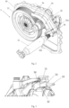
Fig. 1 schematically shows a front view of a transmission system according to the present invention; -
Fig. 2 schematically shows a 3D view of the transmission system shown inFig. 1 ; -
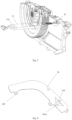
Fig. 3 schematically shows a partial cut-away view of a fluid passage of the transmission system shown inFig. 1 ; -
Fig. 4 schematically shows another view of the transmission system shown inFig. 1 ; -
Fig. 5 schematically shows another partial cut-away view of the transmission system shown inFig. 1 ; and -
Fig. 6 schematically shows a 3D view of a second side wall of the fluid passage shown inFig. 3 . - The technical solutions in embodiments of the present invention will be described clearly and completely below with reference to the drawings in embodiments of the present invention. Obviously, the embodiments described are only some, not all, of the embodiments of the present invention. All other embodiments obtained by those skilled in the art based on embodiments of the present invention without inventive effort shall all fall within the scope of protection of the present invention.
- The expression "an embodiment" or "embodiment" as used herein means a specific feature, structure or characteristic that may be included in at least one implementation of the present invention. In the description of the present invention, it should be understood that orientational or positional relationships indicated by the terms "up", "down", "left", "right", "top", "bottom", etc. are based on the orientational or positional relationships shown in the drawings, and are merely intended to facilitate and simplify the description of the present invention, rather than indicating or implying that the apparatus or element referred to must have a specific orientation or be constructed and operated in a specific orientation, and therefore should not be construed as limiting the present invention.
- In the present invention, "axial direction" refers to the direction of the central axis of the first gear of the reducer, and "radial direction" refers to a direction that is perpendicular to the central axis.
- For brevity, only components that are closely related to the present invention are schematically shown in
Figs. 1 to 6 . -
Figs. 1 and2 schematically show an embodiment of the transmission system according to the present invention. The transmission system comprises a housing, and areducer 1 and amotor 2 that are arranged in the housing, wherein the housing comprises acover part 10 and a main housing not shown inFig. 1 , thecover part 10 covering the housing of the transmission system from an end face. In addition, a lubrication system is further arranged in the housing, comprising afluid passage 3 and a liquid collection tank 4 that is used for a lubricating medium and approximately corresponds in height to a lower part of thereducer 1. - As shown in
Fig. 2 , thereducer 1 comprises afirst gear 11 that is near thecover part 10 of the housing; in this embodiment, thefirst gear 11 is a reducer gear. In other optional embodiments that are not shown, the first gear may also be another gear of the reducer. - A
motor shaft 21 of amotor 2 is also provided near thecover part 10 of the housing, wherein an axial direction of themotor shaft 21 and a central axis of thefirst gear 11 extend parallel to each other. Themotor shaft 21 is provided with a hollow cavity; as shown inFig. 5 ,multiple perforations 21a that extend radially are provided on the hollow cavity, used for connecting the hollow cavity with a motor winding that surrounds the outside of themotor shaft 21. - As shown in
Figs. 1 and2 , afluid passage 3 that extends between thereducer 1 and themotor shaft 21 is provided. Thisfluid passage 3 extends in a bent manner, and aninlet 3a thereof points to thefirst gear 11 of thereducer 1, and anoutlet 3b thereof communicates with the hollow cavity of themotor shaft 21. - As shown in
Fig. 3 , thefluid passage 3 comprises atop wall 31, abottom wall 32 and two side walls, that is, afirst side wall 33 and asecond side wall 34. As shown inFigs. 1 and2 , thetop wall 31, thebottom wall 32 and thefirst side wall 33 are integrally cast with thecover part 10 of the housing of the transmission system, and thesecond side wall 34 is constructed as an independent baffle. As shown inFig. 6 , thesecond side wall 34 is constructed as a flat baffle that has a cross section which extends in a bend, and is fixedly connected to thebottom wall 32 by means of afixing part 342 at a lower edge of the baffle, preferably by a threaded connection or rivet joint. Thus, a passage is formed which has a substantially rectangular cross section and is basically sealed in a length direction. Aprotrusion 341 that extends outward is further provided on thesecond side wall 34, theprotrusion 341 comprising several reinforcement parts that extend radially. Theprotrusion 341 is further described in detail below. - As shown in
Fig. 1 , a housing wall of the main housing partially surrounds thefirst gear 11, and at theinlet 3a of thefluid passage 3, an extension line of thetop wall 31 is tangent to the housing wall surrounding thefirst gear 11 of thereducer 1. - For clarity, the
top wall 31 of thefluid passage 3 is invisible inFig. 2 , so that the interior of thefluid passage 3 is shown more clearly. - The
outlet 3b of thefluid passage 3 is located at a terminal end of thefluid passage 3 and extends downward from thebottom wall 32, and communicates with the hollow cavity of themotor shaft 21. As shown inFig. 5 , a cavity of theoutlet 3b communicates substantially perpendicularly with the hollow cavity of the motor shaft, and a main passage of thefluid passage 3 is thus formed, and lubricating medium that has been flung out by thefirst gear 11 passes from theinlet 3a through the main passage and into the hollow cavity of themotor shaft 21 from theoutlet 3b. - In addition, the
bottom wall 32 comprises astop rib 32a that protrudes upward, thisstop rib 32a extending in a width direction of thefluid passage 3 upstream of theoutlet 3b, and correspondingly, theprotrusion 341 of thesecond side wall 34 comprises abranch outlet 341a constructed as a through hole, and thus a branch passage is formed by means of thestop rib 32a and thebranch outlet 341a of theprotrusion 341. - When the transmission system operates, the
first gear 11 of thereducer 1 rotates, and a lower part thereof carries up lubricating medium in the liquid collection tank 4, so that thefirst gear 11 and even other gears in the transmission system are lubricated. Lubricating medium that is flung off at a tangent by thefirst gear 11 enters thefluid passage 3 from theinlet 3a of thefluid passage 3. Since themotor shaft 21 of themotor 2 rotates, negative pressure is formed in the hollow cavity of themotor shaft 21, and said hollow cavity communicates with theoutlet 3b of thefluid passage 3; therefore, the lubricating medium in thefluid passage 3 is continuously sucked into the hollow cavity of themotor shaft 21 under the effect of negative pressure, and is conveyed out via theradially extending perforation 21a from the hollow cavity to a winding outside, so as to cool themotor 2. - In addition, some of the lubricating medium flowing in the
fluid passage 3 is intercepted by thestop rib 32a, and flows out from thebranch outlet 341a. In the embodiment shown inFig. 6 , thebranch outlet 341a points down, so that lubricating medium flowing out via the branch passage is conveyed out to a component located below thefluid passage 3, thereby lubricating same, and finally falls down and is collected in the liquid collection tank 4 below. - Thus, the lubricating medium can be actively guided from the
reducer 1 to themotor 2 without the need for an additional pump apparatus, so that a dual function of lubrication and cooling can be realized with a simple structure. - According to another aspect of the present invention, a vehicle is further provided, comprising the transmission system described above. The vehicle may be a plug-in hybrid electric vehicle, or a battery electric vehicle or another type of motor vehicle. Based on the above, the vehicle can realize the functions of the motor component and motor described above, and has the advantages described above.
- Certain features, structures or characteristics in one or more embodiments of the present application may be combined appropriately.
- Unless otherwise defined, all of the terms (including technical and scientific terms) used herein have the same meanings as those commonly understood by those skilled in the art. It should also be understood that terms such as those defined in a common dictionary should be interpreted as having the same meanings as they have in the context of the related art, rather than being interpreted in an idealized or extremely formalized sense, unless expressly so defined herein.
- The above is a description of the present invention and should not be regarded as limiting it. Although certain exemplary embodiments of the present invention have been described, those skilled in the art will readily understand that many modifications may be made to the exemplary embodiments without departing from the novel teaching and advantages of the present invention. Therefore, all such modifications are intended to be included within the scope of the present invention as defined by the claims. It should be understood that the above is a description of the present invention and the present invention should not be deemed to be limited to the specific embodiments disclosed herein; in addition, modifications made to the disclosed embodiments and other embodiments are intended to be included within the scope of the present invention.
-
- 1
- Reducer
- 10
- Cover part
- 11
- First gear
- 2
- Motor
- 21
- Motor shaft
- 21a
- Perforation
- 3
- Fluid passage
- 3a
- Inlet
- 3b
- Outlet
- 31
- Top wall
- 32
- Bottom wall
- 32a
- Stop rib
- 33
- First side wall
- 34
- Second side wall
- 341
- Protrusion
- 341a
- Branch outlet
- 342
- Fixing part
Claims (12)
- A transmission system for a vehicle, comprising:a housing comprising a main housing and a cover part (10);a reducer (1) and a motor (2) arranged in the housing;a lubrication system arranged in the housing and comprising:a fluid passage (3) extending between the reducer (1) and the motor (2),characterized in that the fluid passage (3) extends from the first gear (11) of the reducer (1) to the motor shaft (21) of the motor (2) to guide the lubricating medium to the motor (2) by means of the fluid passage (3) to cool the motor (2).
- The transmission system according to Claim 1, characterized in that,
the fluid passage (3) comprises a bottom wall (32) and a first side wall (33), and the bottom wall (32) and the first side wall (33) are integrally constructed with the cover part of the housing. - The transmission system according to Claim 2, characterized in that,
the lubrication system comprises a baffle forming a second side wall (34) of the fluid passage (3) remote from the housing, said second side wall being fixedly connected to the bottom wall (32). - The transmission system according to Claim 1, characterized in that,
an inlet (3a) of the fluid passage (3) is directed to a first gear (11) of the reducer (1) to receive a lubricating medium transmitted from the first gear of the reducer (1) so that it can be fed into the fluid passage (3) via the inlet. - The transmission system according to Claim 4, characterized in that,
the housing wall of the main housing at least partially surrounds the first gear (11), and at the inlet of the fluid passage (3) an extension line of the top wall (31) of the fluid passage (3) is tangent to the housing wall surrounding the first gear (11). - The transmission system according to Claim 2, characterized in that,
an outlet (3b) of the fluid passage (3) extends downward from a bottom wall (32) of the fluid passage (3) and is in communication with a hollow cavity of the motor shaft (21). - The transmission system according to Claim 6, characterized in that,
the hollow cavity includes at least one perforation (21a) extending in a radial direction. - The transmission system according to Claim 7, characterized in that,
a negative pressure is generated in the hollow cavity by the rotation of the motor shaft (21), thereby pumping the lubricating medium from the reducer (1) to the motor (2) via the fluid passage (3). - The transmission system according to Claim 1, characterized in that,
the fluid passage (3) comprises a stop rib (32a) arranged on the bottom wall (32) and a branch passage cooperating with the bottom wall (32) for shunting the lubricating medium guided in the fluid passage (3). - The transmission system according to Claim 9, characterized in that,
the branch passage includes a hollow protrusion (341) extending outwardly from the second sidewall (34), wherein the protrusion (341) includes a branch outlet (341a). - The transmission system according to Claim 1, characterized in that,
the first gear (11) is a reducer gear. - A vehicle comprising the transmission system of any one of claims 1 to 11.
Applications Claiming Priority (1)
| Application Number | Priority Date | Filing Date | Title |
|---|---|---|---|
| CN202310686648.8A CN119103330A (en) | 2023-06-09 | 2023-06-09 | Transmission system and vehicle |
Publications (2)
| Publication Number | Publication Date |
|---|---|
| EP4474679A1 true EP4474679A1 (en) | 2024-12-11 |
| EP4474679B1 EP4474679B1 (en) | 2026-03-18 |
Family
ID=91465200
Family Applications (1)
| Application Number | Title | Priority Date | Filing Date |
|---|---|---|---|
| EP24180664.5A Active EP4474679B1 (en) | 2023-06-09 | 2024-06-07 | Transmission system and vehicle |
Country Status (5)
| Country | Link |
|---|---|
| US (1) | US20240408952A1 (en) |
| EP (1) | EP4474679B1 (en) |
| JP (1) | JP2024177149A (en) |
| KR (1) | KR20240174858A (en) |
| CN (1) | CN119103330A (en) |
Citations (5)
| Publication number | Priority date | Publication date | Assignee | Title |
|---|---|---|---|---|
| US7059443B2 (en) * | 2002-11-29 | 2006-06-13 | Honda Motor Co., Ltd. | Motor-cooling structure of front-and-rear-wheel-drive vehicle |
| US20190145509A1 (en) * | 2017-11-13 | 2019-05-16 | Zhejiang Xin Precision Machinery Co., Ltd. | Pure electric vehicle transmission with novel lubrication structure |
| US10823279B2 (en) * | 2015-10-30 | 2020-11-03 | Voith Patent Gmbh | Spur gear transmission |
| US20230087205A1 (en) * | 2020-05-27 | 2023-03-23 | Huawei Digital Power Technologies Co., Ltd. | Power Assembly and Electric Vehicle |
| JP7281639B2 (en) * | 2019-06-28 | 2023-05-26 | ニデック株式会社 | motor unit |
-
2023
- 2023-06-09 CN CN202310686648.8A patent/CN119103330A/en active Pending
-
2024
- 2024-06-07 JP JP2024092997A patent/JP2024177149A/en active Pending
- 2024-06-07 US US18/736,895 patent/US20240408952A1/en active Pending
- 2024-06-07 EP EP24180664.5A patent/EP4474679B1/en active Active
- 2024-06-10 KR KR1020240074855A patent/KR20240174858A/en active Pending
Patent Citations (5)
| Publication number | Priority date | Publication date | Assignee | Title |
|---|---|---|---|---|
| US7059443B2 (en) * | 2002-11-29 | 2006-06-13 | Honda Motor Co., Ltd. | Motor-cooling structure of front-and-rear-wheel-drive vehicle |
| US10823279B2 (en) * | 2015-10-30 | 2020-11-03 | Voith Patent Gmbh | Spur gear transmission |
| US20190145509A1 (en) * | 2017-11-13 | 2019-05-16 | Zhejiang Xin Precision Machinery Co., Ltd. | Pure electric vehicle transmission with novel lubrication structure |
| JP7281639B2 (en) * | 2019-06-28 | 2023-05-26 | ニデック株式会社 | motor unit |
| US20230087205A1 (en) * | 2020-05-27 | 2023-03-23 | Huawei Digital Power Technologies Co., Ltd. | Power Assembly and Electric Vehicle |
Also Published As
| Publication number | Publication date |
|---|---|
| KR20240174858A (en) | 2024-12-17 |
| JP2024177149A (en) | 2024-12-19 |
| CN119103330A (en) | 2024-12-10 |
| US20240408952A1 (en) | 2024-12-12 |
| EP4474679B1 (en) | 2026-03-18 |
Similar Documents
| Publication | Publication Date | Title |
|---|---|---|
| EP3892892B1 (en) | Oil lubrication mechanism for front bearing of water-cooled motor and motor driving assembly | |
| KR20190090347A (en) | Vehicle drive device | |
| CN218670558U (en) | Lubricating structure of speed reducer and speed reducer | |
| CN102943867B (en) | Lubricating mechanism of vehicle transmission case | |
| EP4474679A1 (en) | Transmission system and vehicle | |
| CN117628146A (en) | Gearboxes, electric drivetrain systems and motor vehicles | |
| CN218718703U (en) | Transmission integrated lubricating system, transmission and vehicle | |
| CN210371929U (en) | Oil-throwing-preventing structure of reduction gearbox | |
| CN214331432U (en) | Transmission bearing splash lubrication structure | |
| CN219712284U (en) | A lubrication structure for an electric axle | |
| WO2025232386A1 (en) | Transmission device, driving device, and vehicle | |
| EP4571145B1 (en) | Power transmission device | |
| CN118316234A (en) | Electric drive assembly and vehicle with same | |
| CN214838318U (en) | Structure for ensuring full active lubrication and oil absorption of three-in-one transmission | |
| CN214999307U (en) | Transmission and vehicle | |
| CN211599498U (en) | Transmission housing, gearbox | |
| CN116398610B (en) | Lubricating structure of electric axle | |
| CN223434716U (en) | Reducer housing, reducer assembly and vehicle | |
| CN214788933U (en) | Vehicle-mounted compressor | |
| CN219549563U (en) | Suction filter structure and vehicle | |
| CN223270578U (en) | Central water outlet gear box with lubrication protection function | |
| US12571466B2 (en) | Drive device for a motor vehicle having an operating medium tank formed in a machine housing | |
| CN221323211U (en) | Oil suction device, gearbox and engineering machinery | |
| CN218829378U (en) | Fixed plate assembly and motor comprising same | |
| CN220850692U (en) | Gearbox structure, gearbox, electric drive axle and vehicle |
Legal Events
| Date | Code | Title | Description |
|---|---|---|---|
| PUAI | Public reference made under article 153(3) epc to a published international application that has entered the european phase |
Free format text: ORIGINAL CODE: 0009012 |
|
| STAA | Information on the status of an ep patent application or granted ep patent |
Free format text: STATUS: THE APPLICATION HAS BEEN PUBLISHED |
|
| AK | Designated contracting states |
Kind code of ref document: A1 Designated state(s): AL AT BE BG CH CY CZ DE DK EE ES FI FR GB GR HR HU IE IS IT LI LT LU LV MC ME MK MT NL NO PL PT RO RS SE SI SK SM TR |
|
| STAA | Information on the status of an ep patent application or granted ep patent |
Free format text: STATUS: REQUEST FOR EXAMINATION WAS MADE |
|
| 17P | Request for examination filed |
Effective date: 20250606 |
|
| RIC1 | Information provided on ipc code assigned before grant |
Ipc: F16H 57/04 20100101AFI20250728BHEP |
|
| GRAP | Despatch of communication of intention to grant a patent |
Free format text: ORIGINAL CODE: EPIDOSNIGR1 |
|
| STAA | Information on the status of an ep patent application or granted ep patent |
Free format text: STATUS: GRANT OF PATENT IS INTENDED |
|
| INTG | Intention to grant announced |
Effective date: 20251007 |
|
| GRAS | Grant fee paid |
Free format text: ORIGINAL CODE: EPIDOSNIGR3 |
|
| GRAA | (expected) grant |
Free format text: ORIGINAL CODE: 0009210 |
|
| STAA | Information on the status of an ep patent application or granted ep patent |
Free format text: STATUS: THE PATENT HAS BEEN GRANTED |
|
| AK | Designated contracting states |
Kind code of ref document: B1 Designated state(s): AL AT BE BG CH CY CZ DE DK EE ES FI FR GB GR HR HU IE IS IT LI LT LU LV MC ME MK MT NL NO PL PT RO RS SE SI SK SM TR |
|
| REG | Reference to a national code |
Ref country code: CH Ref legal event code: F10 Free format text: ST27 STATUS EVENT CODE: U-0-0-F10-F00 (AS PROVIDED BY THE NATIONAL OFFICE) Effective date: 20260318 Ref country code: GB Ref legal event code: FG4D |
|
| REG | Reference to a national code |
Ref country code: IE Ref legal event code: FG4D |
|
| REG | Reference to a national code |
Ref country code: DE Ref legal event code: R096 Ref document number: 602024003230 Country of ref document: DE |