EP4474656A1 - Laufradarchitektur zur kühllüftergeräuschreduzierung - Google Patents
Laufradarchitektur zur kühllüftergeräuschreduzierung Download PDFInfo
- Publication number
- EP4474656A1 EP4474656A1 EP23216175.2A EP23216175A EP4474656A1 EP 4474656 A1 EP4474656 A1 EP 4474656A1 EP 23216175 A EP23216175 A EP 23216175A EP 4474656 A1 EP4474656 A1 EP 4474656A1
- Authority
- EP
- European Patent Office
- Prior art keywords
- blade
- impeller
- type
- blades
- blade type
- Prior art date
- Legal status (The legal status is an assumption and is not a legal conclusion. Google has not performed a legal analysis and makes no representation as to the accuracy of the status listed.)
- Withdrawn
Links
Images




Classifications
-
- F—MECHANICAL ENGINEERING; LIGHTING; HEATING; WEAPONS; BLASTING
- F04—POSITIVE - DISPLACEMENT MACHINES FOR LIQUIDS; PUMPS FOR LIQUIDS OR ELASTIC FLUIDS
- F04D—NON-POSITIVE-DISPLACEMENT PUMPS
- F04D29/00—Details, component parts, or accessories
- F04D29/58—Cooling; Heating; Diminishing heat transfer
- F04D29/582—Cooling; Heating; Diminishing heat transfer specially adapted for elastic fluid pumps
-
- F—MECHANICAL ENGINEERING; LIGHTING; HEATING; WEAPONS; BLASTING
- F04—POSITIVE - DISPLACEMENT MACHINES FOR LIQUIDS; PUMPS FOR LIQUIDS OR ELASTIC FLUIDS
- F04D—NON-POSITIVE-DISPLACEMENT PUMPS
- F04D29/00—Details, component parts, or accessories
- F04D29/66—Combating cavitation, whirls, noise, vibration or the like; Balancing
- F04D29/661—Combating cavitation, whirls, noise, vibration or the like; Balancing especially adapted for elastic fluid pumps
- F04D29/666—Combating cavitation, whirls, noise, vibration or the like; Balancing especially adapted for elastic fluid pumps by means of rotor construction or layout, e.g. unequal distribution of blades or vanes
-
- F—MECHANICAL ENGINEERING; LIGHTING; HEATING; WEAPONS; BLASTING
- F04—POSITIVE - DISPLACEMENT MACHINES FOR LIQUIDS; PUMPS FOR LIQUIDS OR ELASTIC FLUIDS
- F04D—NON-POSITIVE-DISPLACEMENT PUMPS
- F04D17/00—Radial-flow pumps, e.g. centrifugal pumps; Helico-centrifugal pumps
- F04D17/08—Centrifugal pumps
- F04D17/16—Centrifugal pumps for displacing without appreciable compression
-
- F—MECHANICAL ENGINEERING; LIGHTING; HEATING; WEAPONS; BLASTING
- F04—POSITIVE - DISPLACEMENT MACHINES FOR LIQUIDS; PUMPS FOR LIQUIDS OR ELASTIC FLUIDS
- F04D—NON-POSITIVE-DISPLACEMENT PUMPS
- F04D25/00—Pumping installations or systems
- F04D25/02—Units comprising pumps and their driving means
- F04D25/08—Units comprising pumps and their driving means the working fluid being air, e.g. for ventilation
-
- F—MECHANICAL ENGINEERING; LIGHTING; HEATING; WEAPONS; BLASTING
- F04—POSITIVE - DISPLACEMENT MACHINES FOR LIQUIDS; PUMPS FOR LIQUIDS OR ELASTIC FLUIDS
- F04D—NON-POSITIVE-DISPLACEMENT PUMPS
- F04D29/00—Details, component parts, or accessories
- F04D29/26—Rotors specially for elastic fluids
- F04D29/28—Rotors specially for elastic fluids for centrifugal or helico-centrifugal pumps for radial-flow or helico-centrifugal pumps
- F04D29/281—Rotors specially for elastic fluids for centrifugal or helico-centrifugal pumps for radial-flow or helico-centrifugal pumps for fans or blowers
-
- F—MECHANICAL ENGINEERING; LIGHTING; HEATING; WEAPONS; BLASTING
- F04—POSITIVE - DISPLACEMENT MACHINES FOR LIQUIDS; PUMPS FOR LIQUIDS OR ELASTIC FLUIDS
- F04D—NON-POSITIVE-DISPLACEMENT PUMPS
- F04D29/00—Details, component parts, or accessories
- F04D29/26—Rotors specially for elastic fluids
- F04D29/28—Rotors specially for elastic fluids for centrifugal or helico-centrifugal pumps for radial-flow or helico-centrifugal pumps
- F04D29/281—Rotors specially for elastic fluids for centrifugal or helico-centrifugal pumps for radial-flow or helico-centrifugal pumps for fans or blowers
- F04D29/282—Rotors specially for elastic fluids for centrifugal or helico-centrifugal pumps for radial-flow or helico-centrifugal pumps for fans or blowers the leading edge of each vane being substantially parallel to the rotation axis
-
- F—MECHANICAL ENGINEERING; LIGHTING; HEATING; WEAPONS; BLASTING
- F04—POSITIVE - DISPLACEMENT MACHINES FOR LIQUIDS; PUMPS FOR LIQUIDS OR ELASTIC FLUIDS
- F04D—NON-POSITIVE-DISPLACEMENT PUMPS
- F04D29/00—Details, component parts, or accessories
- F04D29/26—Rotors specially for elastic fluids
- F04D29/28—Rotors specially for elastic fluids for centrifugal or helico-centrifugal pumps for radial-flow or helico-centrifugal pumps
- F04D29/30—Vanes
-
- G—PHYSICS
- G06—COMPUTING OR CALCULATING; COUNTING
- G06F—ELECTRIC DIGITAL DATA PROCESSING
- G06F1/00—Details not covered by groups G06F3/00 - G06F13/00 and G06F21/00
- G06F1/16—Constructional details or arrangements
- G06F1/20—Cooling means
-
- G—PHYSICS
- G06—COMPUTING OR CALCULATING; COUNTING
- G06F—ELECTRIC DIGITAL DATA PROCESSING
- G06F1/00—Details not covered by groups G06F3/00 - G06F13/00 and G06F21/00
- G06F1/16—Constructional details or arrangements
- G06F1/20—Cooling means
- G06F1/203—Cooling means for portable computers, e.g. for laptops
-
- F—MECHANICAL ENGINEERING; LIGHTING; HEATING; WEAPONS; BLASTING
- F05—INDEXING SCHEMES RELATING TO ENGINES OR PUMPS IN VARIOUS SUBCLASSES OF CLASSES F01-F04
- F05D—INDEXING SCHEME FOR ASPECTS RELATING TO NON-POSITIVE-DISPLACEMENT MACHINES OR ENGINES, GAS-TURBINES OR JET-PROPULSION PLANTS
- F05D2250/00—Geometry
- F05D2250/10—Two-dimensional
- F05D2250/19—Two-dimensional machined; miscellaneous
- F05D2250/191—Two-dimensional machined; miscellaneous perforated
-
- G—PHYSICS
- G06—COMPUTING OR CALCULATING; COUNTING
- G06F—ELECTRIC DIGITAL DATA PROCESSING
- G06F2200/00—Indexing scheme relating to G06F1/04 - G06F1/32
- G06F2200/20—Indexing scheme relating to G06F1/20
- G06F2200/201—Cooling arrangements using cooling fluid
Definitions
- cooling fan to mitigate the heat generated by components such as central processing units (CPUs) or graphics processing units (GPUs).
- components such as central processing units (CPUs) or graphics processing units (GPUs).
- CPUs central processing units
- GPUs graphics processing units
- an impeller in the cooling fan speeds up to increase airflow and remove the heat.
- impellers generate noise and the faster the impeller spins, the louder the noise it produces. Accordingly, reducing the noise of a cooling fan without compromising its cooling performance is desirable.
- laptop computers may have one or more heat-generating central processing units (CPUs) or graphics processing units (GPUs).
- CPUs central processing units
- GPUs graphics processing units
- a cooling fan is usually employed.
- the cooling fan includes an impeller inside a housing.
- the impeller generally has a circular shape, comprising a plurality of blades attached to a hub that is powered by a motor.
- the impeller may speed up to increase airflow and remove the heat.
- impellers generate noise, and as the impeller speeds up, it generates more noise, which adversely affects the product's acoustics and hence, the user experience.
- the faster the impeller spins the louder the noise it produces.
- acoustics and thermals are closely related, and reducing the noise of a cooling fan without compromising its cooling performance presents a technical problem.
- variable speed cooling fans Some solutions use larger impeller blades to move more air at a lower impeller speed, and some other solutions implement variable speed cooling fans. However, many consumer products are too limited in available space to accommodate larger impeller blades and/or may generate too much heat during operation to successfully employ a variable speed cooling fan.
- aspects of the present disclosure provide a technical solution to this technical problem and other related enhancements, in the form of impeller architecture for cooling fan noise reduction.
- Various embodiments include variable blade lengths, effecting a variable diameter.
- Other embodiments include variations in blade edges and/or variations in blade surface integrity.
- the herein provided architectures and methods for creating same reduce acoustics while delivering the required performance for consumer products such as laptops.
- Embodiments can be detected with a visual inspection of the impeller itself, to look for the diameter and blade variations that are observable, the blade variations occur as a function superimposed on the sequential order of the blades, as disclosed hereinbelow.
- a more detailed description of the aspects of the present disclosure follows a terminology section.
- a "computing system” refers to any of a variety of computing devices and includes systems comprising multiple discrete physical components.
- the computing systems are implemented in a laptop notebook, such as an enterprise notebook application, a consumer notebook application, gaming notebook application.
- a computing system can be in a desktop environment, such as a workstation, a mini desktop computer.
- the computing system can also be in wearable devices such as VR gaming computes.
- the computing systems can also be located in a data center environment, such as an enterprise data center (e.g., a data center owned and operated by a company and typically located on company premises), managed services data center (e.g., a data center managed by a third party on behalf of a company), a colocated data center (e.g., a data center in which data center infrastructure is provided by the data center host and a company provides and manages their own data center components (servers, etc.)), cloud data center (e.g., a data center operated by a cloud services provider that host companies applications and data), and an edge data center (e.g., a data center, typically having a smaller footprint than other data center types, located close to the geographic area that it serves).
- enterprise data center e.g., a data center owned and operated by a company and typically located on company premises
- managed services data center e.g., a data center managed by a third party on behalf of a company
- colocated data center e.g.
- processor unit may refer to any device or portion of a device that processes electronic data from registers and/or memory to transform that electronic data into other electronic data that may be stored in registers and/or memory.
- a processor unit may be a system-on-a-chip (SOC), and/or include one or more digital signal processors (DSPs), application-specific integrated circuits (ASICs), central processing units (CPUs), graphics processing units (GPUs), general-purpose GPUs (GPGPUs), accelerated processing units (APUs), field-programmable gate arrays (FPGAs), neural network processing units (NPUs), data processor units (DPUs), accelerators (e.g., graphics accelerator, compression accelerator, artificial intelligence accelerator), controller cryptoprocessors (specialized processors that execute cryptographic algorithms within hardware), server processors, controllers, or any other suitable type of processor units.
- the processor unit can be referred to as an XPU (or xPU).
- a variety of consumer products include one or more heat generating components (e.g., a CPU and/or GPU) and include a cooling fan in which embodiments of the impeller architecture for cooling fan noise reduction may be implemented.
- a heat generating component e.g., a CPU and/or GPU
- a cooling fan in which embodiments of the impeller architecture for cooling fan noise reduction may be implemented.
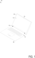
- FIG. 1 an exemplary consumer product is embodied as a compute device 100.
- the compute device 100 includes a housing comprising a lid portion 102 and a base portion 104.
- the lid portion 102 includes a display 112, and the base portion 104 includes a keyboard 114.
- the illustrative compute device 100 is embodied as a laptop with a clamshell configuration with one or more hinges 118 joining the base portion 104 and the lid portion 102. Accordingly, compute device 100 can be in an open configuration (shown in FIG. 1 ) or a closed configuration, in which the lid portion 102 is positioned on top of the base portion 104 with the display 112 facing downwards above the keyboard on the base portion 104 (e.g., see FIG. 2 ).
- the compute device 100 may include a display that can rotate up to 360°, allowing the compute device 100 to be in a book configuration, a tablet configuration, or the like.
- the compute device 100 may be a 2-in-1 device, with a lid portion 102 that can separate from the base portion 104.
- the compute device 100 may embody a single housing without hinges 118.
- the display 112 may be any suitable size and/or resolution, such as a 5-18-inch display, with a resolution from 340 x 480 to 3820 x 2400.
- the display 112 may use any suitable display technology, such as LED, OLED, QD-LED, electronic paper display, and may be a touchscreen display.
- the lid portion 102 may also include a camera 116.
- the camera 116 may include one or more fixed or adjustable lenses and one or more image sensors.
- the image sensors may be any suitable type of image sensors, such as a CMOS or CCD image sensor.
- the camera 116 may have any suitable aperture, focal length, field of view, etc. For example, the camera 116 may have a field of view of 60-110° in the azimuthal and/or elevation directions.
- the compute device 100 may also be another portable or nonportable electronic device, such as a tablet, a desktop computer, a server computer, or the like.
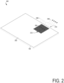
- FIG. 2 A view 200 of the bottom of the compute device 100 is shown in FIG. 2 .
- a portion of the housing referred to as a cover 202 (sometimes, D cover) is on the bottom of the base portion 104.
- Air intake holes 204 are defined in the cover to allow intake air 206 to pass through the base portion 104 into the cooling fan assembly 212 (shortened herein to cooling fan and/or simply "fan” 212).
- the cooling fan 212 is often located near heat generating component(s) (not shown) to dissipate heat or exhaust air 208 from a primary air exhaust vent 210 of the housing.
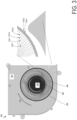
- FIG. 3 illustrates a cooling fan 300 within a fan housing 301 with impeller 302 architecture, in accordance with various embodiments.
- a hub component 304 that is circular with a circumference 306 generally spins in direction 310 responsive to a motor, not shown.
- the spinning hub component 304 causes the impeller 302 to spin and direct airflow.
- the impeller 302 includes a plurality of blades 308; individual ones of the blades 308 have a first end and are attached to the hub component 304 in a sequential order, such that sequential first ends are attached to the circumference 306 and respective second ends extend radially outward to an impeller diameter, as shown.
- sequential order means consecutive or that the blades are arranged in a succeeding order. For example, if there are N blades, they are arranged around the circumference of the hub component 304 as blade 1, blade 2, blade 3, blade 4,. . . blade N.
- Embodiments introduce a methodology to vary the blades 308 in the impeller architecture.
- individual ones of the blades 308 have a "blade type" that varies from one to the next.
- the blade type includes at least two distinctly different manifestations.
- a variety of different blade types may be implemented.
- the manner (i.e., method, or way) that the blade type varies from one blade to a succeeding blade has an observable pattern; specifically, the blade type varies as a function of an indexing function applied to the sequential order.
- the indexing function may be "odd numbers,” “even numbers,” “prime numbers,” or other sequencing functions.
- the indexing function is odd numbers, (i.e., every odd numbered blade has a blade type that is different from the remaining blades) and the blade type variation is observed as follows: blade 1 has a first type, blade 2 has a second type, blade 3 has the first type, blade 4 has the second type, etc., to blade N.
- the blade type is a blade length that includes a first length (blade 312-1 and blade 312-2) and a second length (blade 314-1 and blade 314-2).
- the blade length difference appears as "staggered blades" and embodiments manifest as an impeller 302 with a variable perimeter 400, comprising blades creating a first diameter 316-1 associated with the first blade length and blades creating a second diameter 316-2 associated with the second blade length.
- the first blade type may be assigned a baseline blade type and the second blade type may be assigned a modified blade type, such that modified blades appear as a function of the indexing function (e.g., every odd blade is longer/shorter/notched, etc.).
- a baseline impeller diameter 402 is shown, representing blade types that are blade lengths, in which there is a baseline (or default) blade length.
- the application of the indexing function to the sequential order results, in this example, in a "staggered blade" appearance in a top down view, as illustrated.
- Scenario 1 illustrates an impeller perimeter when staggered blades have a length that is larger (longer) than the baseline blade length.
- Scenario 2 illustrates an impeller perimeter when staggered blades have a length that is smaller (shorter) than the baseline blade length.
- Scenario 3 illustrates an impeller perimeter when staggered blades have a length that is smaller (shorter) than the baseline blade length and remaining blades have a length that is larger (longer) than the baseline blade length.
- Scenario 4 illustrates an impeller perimeter when staggered blades have a length that is larger (longer) than the baseline blade length, and remaining blades have a length that is smaller (shorter) than the baseline blade length.
- FIG. 5 is a simple blade illustration for a more detailed blade type discussion.
- Blade 500 is shown with blade length 508.
- the first end 506 attaches to the circumference of the hub component.
- the blade type includes a notch 502 on an edge of a blade (e.g., the blade type is "notched edge” or “smooth edge”).
- the notched edge blade types can be further subdivided by one or more combinations of varying the size of the notch ("notch-size” blade type), the shape of the notch ("notch-shape"), and/or the location of the notch ("notch-location” blade type) on the blade edge (e.g., closer to the impeller perimeter, or closer to the hub circumference, or topside or bottom side or combination of more than one).
- notchshapes include regular shapes, such as circles, ovals, rectangles, and irregular shapes.
- the notch-location blade types can further be subdivided into notches that are distributed radially along a blade, and notches that are distributed axially across a blade.
- the notched edge blade type can include a variation in a number of notches on the blade edge.
- the cooling fan blade rotates, it creates a pressure surface and a suction surface.
- the pressure difference between the pressure and suction surface results in flow curling at trailing edge and vortex generation.
- the notched embodiments reduce the pressure fluctuation along periphery through the pressure balance feature/notch. This reduces local turbulence at a blade radial location or a tip region, resulting in reduced broadband noise.
- the nonuniform distribution of blade type variations shifts the noise spectrum output of the cooling fan to lower frequencies resulting in lower perceived noise.
- a perforated blade type includes a through-hole 504 in the blade, and remaining blades are "solid.”
- the perforated blade types can be further subdivided, like what is described above for the notched edge blade types (size, shape, location, number of perforations, etc.). Further still, some embodiments combine both notched and perforated blade types, and some embodiments combine notched, perforated, and blade length blade types.
- FIG. 6 Other embodiments vary the spacing between blades of an impeller, also as a function of the indexing function applied to the sequential order, as shown in FIG. 6 .
- hub component 604 has circumference 606 and rotates in direction 610.
- Individual blades 608 of impeller 602 are attached thereto as described herein.
- four blades are illustrated, separated by spaces or gaps.
- the spaces between sequential first ends deliberately vary by more than about 20%.
- gap 1 (620) may range between+/- 20% from gap 2 (622), which may further be about +/- 20% different than gap 3 (624). Variations in the spaces between sequential first ends can be combined with the other blade type variations described above. Varying blade spacing has the following effect.
- Vortices shed from the blades in the impeller interact with the cutwater and create tonal noise. Whereas, with equal spacing, all vortices from a particular blade interact with cutwater. This results in tonal noise at blade pass frequency and its harmonics due to the uniform pattern of interaction. In the uneven blade gap design, it would create a disruption in the frequency at which these interactions occur, resulting in lower tonal noise.
- FIG. 7 returns to the relationship between noise and airflow for cooling fans.
- a pressure versus air flow graph for the exemplary cooling fan at five volts is depicted on the left of the noise graph, showing a baseline 702 performance that drops as the air flow increases.
- Variations 704 and 706 notably provide increased static pressure at lower airflow.
- all vortices from a particular blade interact with cutwater. This results in tonal noise at blade pass frequency and its harmonics due to the uniform pattern of interaction.
- Using the uneven blade length architectures proposed herein a disruption in the frequency at which these interactions occur is created, resulting in lower tonal noise.
- An exemplary cooling fan was modified to include notched blade types, described above, to quantify the impact of the pressure balance feature/notch. It was observed at same RPM the fan provided 1 ⁇ 1.5 dBA noise reduction, as illustrated with baseline 708 to dashed line 710.
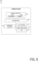
- a compute node 800 includes a compute engine (referred to herein as "compute circuitry") 802, an input/output (I/O) subsystem 808, data storage 810, a communication circuitry subsystem 812, and, optionally, one or more peripheral devices 814.
- the compute node 800 or compute circuitry 802 may perform the operations and tasks attributed to the system 101.
- respective compute nodes 800 may include other or additional components, such as those typically found in a computer (e.g., a display, peripheral devices, etc.). Additionally, in some examples, one or more of the illustrative components may be incorporated in, or otherwise form a portion of, another component.
- the compute node 800 may be embodied as a single device such as an integrated circuit, an embedded system, a field-programmable gate array (FPGA), a system-on-a-chip (SOC), or other integrated system or device.
- the compute node 800 includes or is embodied as a processor 804 and a memory 806.
- the processor 804 may be embodied as any type of processor capable of performing the functions described herein (e.g., executing compile functions and executing an application).
- the processor 804 may be embodied as a multi-core processor(s), a microcontroller, a processing unit, a specialized or special purpose processing unit, or other processor or processing/controlling circuit.
- the processor 804 may be embodied as, include, or be coupled to an FPGA, an application specific integrated circuit (ASIC), reconfigurable hardware or hardware circuitry, or other specialized hardware to facilitate performance of the functions described herein.
- the processor 804 may be embodied as a specialized x-processing unit (xPU) also known as a data processing unit (DPU), infrastructure processing unit (IPU), or network processing unit (NPU).
- xPU e.g., a SmartNIC, or enhanced SmartNIC
- acceleration circuitry e.g., GPUs or programmed FPGAs.
- Such an xPU may be designed to receive programming to process one or more data streams and perform specific tasks and actions for the data streams (such as hosting microservices, performing service management or orchestration, organizing, or managing server or data center hardware, managing service meshes, or collecting and distributing telemetry), outside of the CPU or general-purpose processing hardware.
- a xPU, a SOC, a CPU, and other variations of the processor 804 may work in coordination with each other to execute many types of operations and instructions within and on behalf of the compute node 800.
- the memory 806 may be embodied as any type of volatile (e.g., dynamic random-access memory (DRAM), etc.) or non-volatile memory or data storage capable of performing the functions described herein.
- Volatile memory may be a storage medium that requires power to maintain the state of data stored by the medium.
- Non-limiting examples of volatile memory may include several types of random-access memory (RAM), such as DRAM or static random-access memory (SRAM).
- RAM random-access memory
- SRAM static random-access memory
- SDRAM synchronous dynamic random-access memory
- the memory device is a block addressable memory device, such as those based on NAND or NOR technologies.
- a memory device may also include a three-dimensional crosspoint memory device (e.g., Intel ® 3D XPoint TM memory), or other byte addressable write-in-place nonvolatile memory devices.
- the memory device may refer to the die itself and/or to a packaged memory product.
- 3D crosspoint memory e.g., Intel ® 3D XPoint TM memory
- all or a portion of the memory 806 may be integrated into the processor 804.
- the memory 806 may store various software and data used during operation such as one or more applications, data operated on by the application(s), libraries, and drivers.
- the compute circuitry 802 is communicatively coupled to other components of the compute node 800 via the I/O subsystem 808, which may be embodied as circuitry and/or components to facilitate input/output operations with the compute circuitry 802 (e.g., with the processor 804 and/or the main memory 806) and other components of the compute circuitry 802.
- the I/O subsystem 808 may be embodied as, or otherwise include, memory controller hubs, input/output control hubs, integrated sensor hubs, firmware devices, communication links (e.g., point-to-point links, bus links, wires, cables, light guides, printed circuit board traces, etc.), and/or other components and subsystems to facilitate the input/output operations.
- the I/O subsystem 808 may form a portion of a system-on-a-chip (SoC) and be incorporated, along with one or more of the processor 804, the memory 806, and other components of the compute circuitry 802, into the compute circuitry 802.
- SoC system-on-a-chip
- the one or more illustrative data storage devices 810 may be embodied as any type of devices configured for short-term or long-term storage of data such as, for example, memory devices and circuits, memory cards, hard disk drives, solid-state drives, or other data storage devices.
- Individual data storage devices 810 may include a system partition that stores data and firmware code for the data storage device 810.
- Individual data storage devices 810 may also include one or more operating system partitions that store data files and executables for operating systems depending on, for example, the type of compute node 800.
- the communication subsystem 812 may be embodied as any communication circuit, device, transceiver circuit, or collection thereof, capable of enabling communications over a network between the compute circuitry 802 and another compute device (e.g., an edge gateway of an implementing edge computing system).
- another compute device e.g., an edge gateway of an implementing edge computing system.
- the communication subsystem 812 may implement any of a number of wireless standards or protocols, including but not limited to Institute for Electrical and Electronic Engineers (IEEE) standards including Wi-Fi (IEEE 802.11 family), IEEE 802.16 standards (e.g., IEEE 802.16-2005 Amendment), Long-Term Evolution (LTE) project along with any amendments, updates, and/or revisions (e.g., advanced LTE project, ultra-mobile broadband (UMB) project (also referred to as "3GPP2”), etc.).
- IEEE 802.16 compatible Broadband Wireless Access (BWA) networks are generally referred to as WiMAX networks, an acronym that stands for Worldwide Interoperability for Microwave Access, which is a certification mark for products that pass conformity and interoperability tests for the IEEE 802.16 standards.
- the communication subsystem 812 may operate in accordance with a Global System for Mobile Communication (GSM), General Packet Radio Service (GPRS), Universal Mobile Telecommunications System (UMTS), High Speed Packet Access (HSPA), Evolved HSPA (E-HSPA), or LTE network.
- GSM Global System for Mobile Communication
- GPRS General Packet Radio Service
- UMTS Universal Mobile Telecommunications System
- High Speed Packet Access HSPA
- E-HSPA Evolved HSPA
- LTE LTE network.
- the communication subsystem 812 may operate in accordance with Enhanced Data for GSM Evolution (EDGE), GSM EDGE Radio Access Network (GERAN), Universal Terrestrial Radio Access Network (UTRAN), or Evolved UTRAN (E-UTRAN).
- EDGE Enhanced Data for GSM Evolution
- GERAN GSM EDGE Radio Access Network
- UTRAN Universal Terrestrial Radio Access Network
- E-UTRAN Evolved UTRAN
- the communication subsystem 812 may operate in accordance with Code Division Multiple Access (CDMA), Time Division Multiple Access (TDMA), Digital Enhanced Cordless Telecommunications (DECT), Evolution-Data Optimized (EV-DO), and derivatives thereof, as well as any other wireless protocols that are designated as 3G, 4G, 5G, and beyond.
- CDMA Code Division Multiple Access
- TDMA Time Division Multiple Access
- DECT Digital Enhanced Cordless Telecommunications
- EV-DO Evolution-Data Optimized
- the communication subsystem 812 may operate in accordance with other wireless protocols in other embodiments.
- the communication subsystem 812 may include an antenna to facilitate wireless communications and/or to receive other wireless communications (such as AM or FM radio transmissions).
- the communication subsystem 812 may manage wired communications, such as electrical, optical, or any other suitable communication protocols (e.g., IEEE 802.3 Ethernet standards).
- the communication subsystem 812 may include multiple communication components. For instance, a first communication subsystem 812 may be dedicated to shorter-range wireless communications such as Wi-Fi or Bluetooth, and a second communication subsystem 812 may be dedicated to longer-range wireless communications such as global positioning system (GPS), EDGE, GPRS, CDMA, WiMAX, LTE, EV-DO, or others.
- GPS global positioning system
- EDGE EDGE
- GPRS long-range wireless communications
- CDMA Code Division Multiple Access
- WiMAX Code Division Multiple Access
- LTE Long Term Evolution
- EV-DO Evolution-DO
- the illustrative communication subsystem 812 includes an optional network interface controller (NIC) 820, which may also be referred to as a host fabric interface (HFI).
- NIC network interface controller
- HFI host fabric interface
- the NIC 820 may be embodied as one or more add-in-boards, daughter cards, network interface cards, controller chips, chipsets, or other devices that may be used by the compute node 800 to connect with another compute device (e.g., an edge gateway node).
- the NIC 820 may be embodied as part of a system-on-a-chip (SoC) that includes one or more processors or included on a multichip package that also contains one or more processors.
- SoC system-on-a-chip
- the NIC 820 may include a local processor (not shown) and/or a local memory (not shown) that are both local to the NIC 820.
- the local processor of the NIC 820 may be capable of performing one or more of the functions of the compute circuitry 802 described herein.
- the local memory of the NIC 820 may be integrated into one or more components of the client compute node at the board level, socket level, chip level, and/or other levels.
- a respective compute node 800 may include one or more peripheral devices 814.
- peripheral devices 814 may include any type of peripheral device found in a compute device or server such as audio input devices, a display, other input/output devices, interface devices, and/or other peripheral devices, depending on the particular type of the compute node 800.
- the compute node 800 may be embodied by a respective edge compute node (whether a client, gateway, or aggregation node) in an edge computing system or like forms of appliances, computers, subsystems, circuitry, or other components.
- the compute node 800 may be embodied as any type of device or collection of devices capable of performing various compute functions.
- Respective compute nodes 800 may be embodied as a type of device, appliance, computer, or other "thing" capable of communicating with other compute nodes that may be edge, networking, or endpoint components.
- a compute device may be embodied as a personal computer, server, smartphone, a mobile compute device, a smart appliance, smart camera, an in-vehicle compute system (e.g., a navigation system), a weatherproof or weather-sealed computing appliance, a self-contained device within an outer case, shell, etc., or other device or system capable of performing the described functions.
- FIG. 9 illustrates a multi-processor environment in which embodiments may be implemented.
- Processor units 902 and 904 further comprise cache memories 912 and 914, respectively.
- the cache memories 912 and 914 can store data (e.g., instructions) utilized by one or more components of the processor units 902 and 904, such as the processor cores 908 and 910.
- the cache memories 912 and 914 can be part of a memory hierarchy for the computing system 900.
- the cache memories 912 can locally store data that is also stored in a memory 916 to allow for faster access to the data by the processor unit 902.
- the cache memories 912 and 914 can comprise multiple cache levels, such as level 1 (L1), level 2 (L2), level 3 (L3), level 4 (L4) and/or other caches or cache levels.
- level 1 (L1), level 2 (L2), level 3 (L3), level 4 (L4) and/or other caches or cache levels.
- one or more levels of cache memory e.g., L2, L3, L4 can be shared among multiple cores in a processor unit or among multiple processor units in an integrated circuit component.
- the last level of cache memory on an integrated circuit component can be referred to as a last level cache (LLC).
- One or more of the higher levels of cache levels (the smaller and faster caches) in the memory hierarchy can be located on the same integrated circuit die as a processor core and one or more of the lower cache levels (the larger and slower caches) can be located on an integrated circuit dies that are physically separate from the processor core integrated circuit dies.
- a processor unit can take various forms such as a central processing unit (CPU), a graphics processing unit (GPU), general-purpose GPU (GPGPU), accelerated processing unit (APU), field-programmable gate array (FPGA), neural network processing unit (NPU), data processor unit (DPU), accelerator (e.g., graphics accelerator, digital signal processor (DSP), compression accelerator, artificial intelligence (AI) accelerator), controller, or other types of processing units.
- CPU central processing unit
- GPU graphics processing unit
- GPU general-purpose GPU
- APU accelerated processing unit
- FPGA field-programmable gate array
- NPU neural network processing unit
- DPU data processor unit
- accelerator e.g., graphics accelerator, digital signal processor (DSP), compression accelerator, artificial intelligence (AI) accelerator
- controller or other types of processing units.
- the processor unit can be referred to as an XPU (or xPU).
- a processor unit can comprise one or more of these several types of processing units.
- the computing system comprises one processor unit with multiple cores, and in other embodiments, the computing system comprises a single processor unit with a single core.
- processor unit and “processing unit” can refer to any processor, processor core, component, module, engine, circuitry, or any other processing element described or referenced herein.
- the computing system 900 can comprise one or more processor units that are heterogeneous or asymmetric to another processor unit in the computing system.
- processor units that are heterogeneous or asymmetric to another processor unit in the computing system.
- the processor units 902 and 904 can be located in a single integrated circuit component (such as a multi-chip package (MCP) or multi-chip module (MCM)) or they can be located in separate integrated circuit components.
- An integrated circuit component comprising one or more processor units can comprise additional components, such as embedded DRAM, stacked high bandwidth memory (HBM), shared cache memories (e.g., L3, L4, LLC), input/output (I/O) controllers, or memory controllers. Any of the additional components can be located on the same integrated circuit die as a processor unit, or on one or more integrated circuit dies separate from the integrated circuit dies comprising the processor units. In some embodiments, these separate integrated circuit dies can be referred to as "chiplets”.
- the heterogeneity or asymmetric can be among processor units located in the same integrated circuit component.
- interconnections between dies can be provided by the package substrate, one or more silicon interposers, one or more silicon bridges embedded in the package substrate (such as Intel ® embedded multi-die interconnect bridges (EMIBs)), or combinations thereof.
- EMIBs Intel ® embedded multi-die interconnect bridges
- Processor units 902 and 904 further comprise memory controller logic (MC) 920 and 922.
- MCs 920 and 922 control memories 916 and 918 coupled to the processor units 902 and 904, respectively.
- the memories 916 and 918 can comprise various types of volatile memory (e.g., dynamic random-access memory (DRAM), static random-access memory (SRAM)) and/or non-volatile memory (e.g., flash memory, chalcogenide-based phase-change non-volatile memories), and comprise one or more layers of the memory hierarchy of the computing system.
- DRAM dynamic random-access memory
- SRAM static random-access memory
- non-volatile memory e.g., flash memory, chalcogenide-based phase-change non-volatile memories
- MCs 920 and 922 are illustrated as being integrated into the processor units 902 and 904, in alternative embodiments, the MCs can be external to a processor unit.
- Processor units 902 and 904 are coupled to an Input/Output (I/O) subsystem 930 via point-to-point interconnections 932 and 934.
- the point-to-point interconnection 932 connects a point-to-point interface 936 of the processor unit 902 with a point-to-point interface 938 of the I/O subsystem 930
- the point-to-point interconnection 934 connects a point-to-point interface 940 of the processor unit 904 with a point-to-point interface 942 of the I/O subsystem 930.
- Input/Output subsystem 930 further includes an interface 950 to couple the I/O subsystem 930 to a graphics engine 952.
- the I/O subsystem 930 and the graphics engine 952 are coupled via a bus 954.
- the Input/Output subsystem 930 is further coupled to a first bus 960 via an interface 962.
- the first bus 960 can be a Peripheral Component Interconnect Express (PCIe) bus or any other type of bus.
- PCIe Peripheral Component Interconnect Express
- Various I/O devices 964 can be coupled to the first bus 960.
- a bus bridge 970 can couple the first bus 960 to a second bus 980.
- the second bus 980 can be a low pin count (LPC) bus.
- LPC low pin count
- Various devices can be coupled to the second bus 980 including, for example, a keyboard/mouse 982, audio I/O devices 988, and a storage device 990, such as a hard disk drive, solid-state drive, or another storage device for storing computer-executable instructions (code) 992 or data.
- the code 992 can comprise computer-executable instructions for performing methods described herein.
- Additional components that can be coupled to the second bus 980 include communication device(s) 984, which can provide for communication between the computing system 900 and one or more wired or wireless networks 986 (e.g.
- Wi-Fi Wireless Fidelity
- cellular cellular
- satellite networks via one or more wired or wireless communication links (e.g., wire, cable, Ethernet connection, radio-frequency (RF) channel, infrared channel, Wi-Fi channel) using one or more communication standards (e.g., IEEE 802.11 standard and its supplements).
- wired or wireless communication links e.g., wire, cable, Ethernet connection, radio-frequency (RF) channel, infrared channel, Wi-Fi channel
- RF radio-frequency
- Wi-Fi wireless local area network
- communication standards e.g., IEEE 802.11 standard and its supplements.
- the communication devices 984 can comprise wireless communication components coupled to one or more antennas to support communication between the computing system 900 and external devices.
- the wireless communication components can support various wireless communication protocols and technologies such as Near Field Communication (NFC), IEEE 802.11 (Wi-Fi) variants, WiMax, Bluetooth, Zigbee, 4G Long Term Evolution (LTE), Code Division Multiplexing Access (CDMA), Universal Mobile Telecommunication System (UMTS) and Global System for Mobile Telecommunication (GSM), and 5G broadband cellular technologies.
- the wireless modems can support communication with one or more cellular networks for data and voice communications within a single cellular network, between cellular networks, or between the computing system and a public switched telephone network (PSTN).
- PSTN public switched telephone network
- the system 900 can comprise removable memory such as flash memory cards (e.g., SD (Secure Digital) cards), memory sticks, Subscriber Identity Module (SIM) cards).
- the memory in system 900 (including caches 912 and 914, memories 916 and 918, and storage device 990) can store data and/or computer-executable instructions for executing an operating system 994 and application programs 996.
- Example data includes web pages, text messages, images, sound files, and video data biometric thresholds for particular users or other data sets to be sent to and/or received from one or more network servers or other devices by the system 900 via the one or more wired or wireless networks 986, or for use by the system 900.
- the system 900 can also have access to external memory or storage (not shown) such as external hard drives or cloud-based storage.
- the operating system 994 (also simplified to "OS” herein) can control the allocation and usage of the components illustrated in FIG. 6 and support the one or more application programs 996.
- the application programs 996 can include common computing system applications (e.g., email applications, calendars, contact managers, web browsers, messaging applications) as well as other computing applications.
- a hypervisor (or virtual machine manager) operates on the operating system 994 and the application programs 996 operate within one or more virtual machines operating on the hypervisor.
- the hypervisor is a type-2 or hosted hypervisor as it is running on the operating system 994.
- the hypervisor is a type-1 or "bare-metal" hypervisor that runs directly on the platform resources of the computing system 994 without an intervening operating system layer.
- the applications 996 can operate within one or more containers.
- a container is a running instance of a container image, which is a package of binary images for one or more of the applications 996 and any libraries, configuration settings, and any other information that one or more applications 996 need for execution.
- a container image can conform to any container image format, such as Docker ® , Appc, or LXC container image formats.
- a container runtime engine such as Docker Engine, LXU, or an open container initiative (OCI)-compatible container runtime (e.g., Railcar, CRI-O) operates on the operating system (or virtual machine monitor) to provide an interface between the containers and the operating system 994.
- An orchestrator can be responsible for management of the computing system 900 and various container-related tasks such as deploying container images to the computing system 994, monitoring the performance of deployed containers, and monitoring the utilization of the resources of the computing system 994.
- the computing system 900 can support various additional input devices, represented generally as user interfaces 998, such as a touchscreen, microphone, monoscopic camera, stereoscopic camera, trackball, touchpad, trackpad, proximity sensor, light sensor, electrocardiogram (ECG) sensor, PPG (photoplethysmogram) sensor, galvanic skin response sensor, and one or more output devices, such as one or more speakers or displays.
- user interfaces 998 such as a touchscreen, microphone, monoscopic camera, stereoscopic camera, trackball, touchpad, trackpad, proximity sensor, light sensor, electrocardiogram (ECG) sensor, PPG (photoplethysmogram) sensor, galvanic skin response sensor, and one or more output devices, such as one or more speakers or displays.
- ECG electrocardiogram
- PPG photoplethysmogram
- galvanic skin response sensor galvanic skin response sensor
- Other possible input and output devices include piezoelectric and other haptic I/O devices. Any of the input or output devices can be internal to, external to,
- one or more of the user interfaces 998 may be natural user interfaces (NUIs).
- NUIs natural user interfaces
- the operating system 994 or applications 996 can comprise speech recognition logic as part of a voice user interface that allows a user to operate the system 900 via voice commands.
- the computing system 900 can comprise input devices and logic that allows a user to interact with computing the system 900 via body, hand, or face gestures. For example, a user's hand gestures can be detected and interpreted to provide input to a gaming application.
- the I/O devices 964 can include at least one input/output port comprising physical connectors (e.g., USB, IEEE 1394 (FireWire), Ethernet, RS-232), a power supply (e.g., battery), a global satellite navigation system (GNSS) receiver (e.g., GPS receiver); a gyroscope; an accelerometer; and/or a compass.
- GNSS global satellite navigation system
- a GNSS receiver can be coupled to a GNSS antenna.
- the computing system 900 can further comprise one or more additional antennas coupled to one or more additional receivers, transmitters, and/or transceivers to enable additional functions.
- interconnect technologies such as Intel ® QuickPath Interconnect (QPI), Intel ® Ultra Path Interconnect (UPI), Computer Express Link (CXL), cache coherent interconnect for accelerators (CCIX ® ), serializer/deserializer (SERDES), Nvidia ® NVLink, ARM Infinity Link, Gen-Z, or Open Coherent Accelerator Processor Interface (OpenCAPI).
- QPI QuickPath Interconnect
- UPI Intel ® Ultra Path Interconnect
- CXL Computer Express Link
- CXL Computer Express Link
- CXL cache coherent interconnect for accelerators
- SERDES serializer/deserializer
- Nvidia ® NVLink ARM Infinity Link
- Gen-Z Gen-Z
- Open Coherent Accelerator Processor Interface OpenCAPI
- FIG. 9 illustrates only one example computing system architecture.
- Computing systems based on alternative architectures can be used to implement technologies described herein.
- a computing system can comprise an SoC (system-on-a-chip) integrated circuit incorporating multiple processors, a graphics engine, and additional components.
- SoC system-on-a-chip
- a computing system can connect its constituent component via bus or point-to-point configurations different from that shown in FIG. 9 .
- the illustrated components in FIG. 9 are not required or all-inclusive, as shown components can be removed and other components added in alternative embodiments.
- FIG. 10 is a block diagram of an example processor unit 1000 to execute computer-executable instructions as part of implementing technologies described herein.
- the processor unit 1000 can be a single-threaded core or a multithreaded core in that it may include more than one hardware thread context (or "logical processor") per processor unit.
- FIG. 10 also illustrates a memory 1010 coupled to the processor unit 1000.
- the memory 1010 can be any memory described herein or any other memory known to those of skill in the art.
- the memory 1010 can store computer-executable instructions 1015 (code) executable by the processor unit 1000.
- the processor unit comprises front-end logic 1020 that receives instructions from the memory 1010.
- An instruction can be processed by one or more decoders 1030.
- the decoder 1030 can generate as its output a micro-operation such as a fixed width micro-operation in a predefined format, or generate other instructions, microinstructions, or control signals, which reflect the original code instruction.
- the front-end logic 1020 further comprises register renaming logic 1035 and scheduling logic 1040, which generally allocate resources and queues operations corresponding to converting an instruction for execution.
- the processor unit 1000 further comprises execution logic 1050, which comprises one or more execution units (EUs) 1065-1 through 1065-N. Some processor unit embodiments can include a few execution units dedicated to specific functions or sets of functions. Other embodiments can include only one execution unit or one execution unit that can perform a particular function.
- the execution logic 1050 performs the operations specified by code instructions. After completion of execution of the operations specified by the code instructions, back-end logic 1070 retires instructions using retirement logic 1075. In some embodiments, the processor unit 1000 allows out of order execution but requires in-order retirement of instructions.
- Retirement logic 1075 can take a variety of forms as known to those of skill in the art (e.g., reorder buffers or the like).
- the processor unit 1000 is transformed during execution of instructions, at least in terms of the output generated by the decoder 1030, hardware registers and tables utilized by the register renaming logic 1035, and any registers (not shown) modified by the execution logic 1050.
- any of the disclosed methods can be implemented as computer-executable instructions or a computer program product. Such instructions can cause a computing system or one or more processor units capable of executing computer-executable instructions to perform any of the disclosed methods.
- the term "computer” refers to any computing system, device, or machine described or mentioned herein as well as any other computing system, device, or machine capable of executing instructions.
- the term "computer-executable instruction” refers to instructions that can be executed by any computing system, device, or machine described or mentioned herein as well as any other computing system, device, or machine capable of executing instructions.
- the computer-executable instructions or computer program products as well as any data created and/or used during implementation of the disclosed technologies can be stored on one or more tangible or non-transitory computer-readable storage media, such as volatile memory (e.g., DRAM, SRAM), non-volatile memory (e.g., flash memory, chalcogenide-based phase-change non-volatile memory) optical media discs (e.g., DVDs, CDs), and magnetic storage (e.g., magnetic tape storage, hard disk drives).
- Computer-readable storage media can be contained in computer-readable storage devices such as solid-state drives, USB flash drives, and memory modules.
- any of the methods disclosed herein (or a portion) thereof may be performed by hardware components comprising non-programmable circuitry.
- any of the methods herein can be performed by a combination of non-programmable hardware components and one or more processing units executing computer-executable instructions stored on computer-readable storage media.
- the computer-executable instructions can be part of, for example, an operating system of the computing system, an application stored locally to the computing system, or a remote application accessible to the computing system (e.g., via a web browser). Any of the methods described herein can be performed by computer-executable instructions performed by a single computing system or by one or more networked computing systems operating in a network environment. Computer-executable instructions and updates to the computer-executable instructions can be downloaded to a computing system from a remote server.
- implementation of the disclosed technologies is not limited to any specific computer language or program.
- the disclosed technologies can be implemented by software written in C++, C#, Java, Perl, Python, JavaScript, Adobe Flash, C#, assembly language, or any other programming language.
- the disclosed technologies are not limited to any computer system or type of hardware.
- any of the software-based embodiments can be uploaded, downloaded, or remotely accessed through a suitable communication means.
- suitable communication means include, for example, the Internet, the World Wide Web, an intranet, cable (including fiber optic cable), magnetic communications, electromagnetic communications (including RF, microwave, ultrasonic, and infrared communications), electronic communications, or other such communication means.
- phrases such as “embodiments,” “an aspect of the present disclosure,” “various aspects of the present disclosure,” “some aspects of the present disclosure,” and the like, indicate that some aspects of the present disclosure may have some, all, or none of the features described for other aspects of the present disclosure.
- “First,” “second,” “third,” and the like describe a common object and indicate different instances of like objects being referred to; unless specifically stated, they do not imply a given sequence, either temporally or spatially, in ranking, or any other manner.
- “connected” indicates elements that are in direct physical or electrical contact with each other and “coupled” indicates elements that co-operate or interact with each other, coupled elements may or may not be in direct physical or electrical contact.
- the terms “comprising,” “including,” “having,” and the like are utilized synonymously to denote non-exclusive inclusions.
- a list of items joined by the term "at least one of” can mean any combination of the listed terms.
- the phrase "at least one of A, B and C” can mean A; B; C; A and B; A and C; B and C; or A, B, and C.
- a list of items joined by the term "one or more of' can mean any combination of the listed terms.
- the phrase "one or more of A, B and C” can mean A; B; C; A and B; A and C; B and C; or A, B, and C.
- Example 1 is an impeller, including: a hub component having a circumference; a plurality of blades, individual ones of the blades have a first end and are attached to the hub component in a sequential order, such that sequential first ends are attached to the circumference; and wherein the individual ones of the blades further have a blade type that varies as a function of an indexing function applied to the sequential order.
- Example 2 includes the subject matter of Example 1, wherein the blade type includes a first length or a second length.
- Example 3 includes the subject matter of Example 2, wherein the first length is smaller than the second length.
- Example 4 includes the subject matter of Example 2, wherein the first length is larger than the second length.
- Example 5 includes the subject matter of Example 1, wherein the blade type includes a notched edge or a smooth edge.
- Example 6 includes the subject matter of Example 5 wherein the notched edge further includes one or more notch-location blade types.
- Example 7 includes the subject matter of Example 5 wherein the notched edge further includes one or more notch-size or notch-shape blade types.
- Example 8 includes the subject matter of Example 1, wherein the blade type includes a perforated surface or a solid surface.
- Example 9 includes the subject matter of Example 8 wherein the perforated surface further includes one or more perforation-location blade types.
- Example 10 includes the subject matter of Example 1, wherein the indexing function is even numbers or prime numbers.
- Example 11 includes the subject matter of Example 1, wherein the indexing function includes one or more of even numbers, prime numbers, an arithmetic sequence, a geometric sequence, square numbers, and triangular numbers.
- Example 12 includes the subject matter of any one of Examples 1-11, wherein spaces between sequential first ends are substantially equal.
- Example 13 includes the subject matter of any one of Examples 1-11, wherein spaces between sequential first ends vary by more than 20%.
- Example 14 includes an apparatus, including: a fan housing; and a cooling fan disposed within the fan housing, the cooling fan including: a hub component having a circumference; a plurality of blades, individual ones of the blades have a first end and are attached to the hub component in a sequential order, such that sequential first ends are attached to the circumference; and wherein the individual ones of the blades further have a blade type that varies as a function of an indexing function applied to the sequential order, and the indexing function is one of prime numbers or odd numbers.
- Example 15 includes the subject matter of Example 14, wherein the blade type includes a first length or a second length.
- Example 16 includes the subject matter of Example 14, wherein the blade type includes a notched edge or a smooth edge.
- Example 17 includes the subject matter of Example 14, wherein the blade type includes a perforated surface or a solid surface.
- Example 18 includes the subject matter of Example 14, wherein spaces between sequential first ends vary by more than 20%.
- Example 19 is a compute device, including: a housing including air intake holes and an air exhaust vent; the subject matter of Example 14 disposed within the housing with access to the air intake holes and air exhaust vent; a motherboard disposed within the housing; and a heat generating component attached to the motherboard.
- Example 20 includes the subject matter of Example 19, wherein the housing further comprises a keyboard.
- Example 21 includes the subject matter of Example 19, wherein the housing further comprises a display.
Landscapes
- Engineering & Computer Science (AREA)
- General Engineering & Computer Science (AREA)
- Mechanical Engineering (AREA)
- Theoretical Computer Science (AREA)
- Physics & Mathematics (AREA)
- Human Computer Interaction (AREA)
- General Physics & Mathematics (AREA)
- Computer Hardware Design (AREA)
- Thermal Sciences (AREA)
- Cooling Or The Like Of Electrical Apparatus (AREA)
Applications Claiming Priority (1)
| Application Number | Priority Date | Filing Date | Title |
|---|---|---|---|
| US18/329,763 US20240410396A1 (en) | 2023-06-06 | 2023-06-06 | Impeller architecture for cooling fan noise reduction |
Publications (1)
| Publication Number | Publication Date |
|---|---|
| EP4474656A1 true EP4474656A1 (de) | 2024-12-11 |
Family
ID=89222321
Family Applications (1)
| Application Number | Title | Priority Date | Filing Date |
|---|---|---|---|
| EP23216175.2A Withdrawn EP4474656A1 (de) | 2023-06-06 | 2023-12-13 | Laufradarchitektur zur kühllüftergeräuschreduzierung |
Country Status (2)
| Country | Link |
|---|---|
| US (1) | US20240410396A1 (de) |
| EP (1) | EP4474656A1 (de) |
Families Citing this family (1)
| Publication number | Priority date | Publication date | Assignee | Title |
|---|---|---|---|---|
| US20250142767A1 (en) * | 2023-10-26 | 2025-05-01 | Dell Products L.P. | Low-noise fan for information handling systems |
Citations (3)
| Publication number | Priority date | Publication date | Assignee | Title |
|---|---|---|---|---|
| JPS56120399U (de) * | 1980-02-14 | 1981-09-12 | ||
| FR2851857A1 (fr) * | 2003-02-27 | 2004-09-03 | Valeo Equip Electr Moteur | Dispositif de ventilation perfectionne pour machine electrique tournante |
| US20170346367A1 (en) * | 2014-12-10 | 2017-11-30 | Denso Corporation | Alternating current generator for vehicles |
-
2023
- 2023-06-06 US US18/329,763 patent/US20240410396A1/en not_active Abandoned
- 2023-12-13 EP EP23216175.2A patent/EP4474656A1/de not_active Withdrawn
Patent Citations (3)
| Publication number | Priority date | Publication date | Assignee | Title |
|---|---|---|---|---|
| JPS56120399U (de) * | 1980-02-14 | 1981-09-12 | ||
| FR2851857A1 (fr) * | 2003-02-27 | 2004-09-03 | Valeo Equip Electr Moteur | Dispositif de ventilation perfectionne pour machine electrique tournante |
| US20170346367A1 (en) * | 2014-12-10 | 2017-11-30 | Denso Corporation | Alternating current generator for vehicles |
Also Published As
| Publication number | Publication date |
|---|---|
| US20240410396A1 (en) | 2024-12-12 |
Similar Documents
| Publication | Publication Date | Title |
|---|---|---|
| US12333688B2 (en) | Denoising diffusion generative adversarial networks | |
| EP4155932A1 (de) | Metrik- und sicherheitsbasierte umplanung und automatische skalierung von beschleunigungsdiensten unter verwendung einer programmierbaren netzwerkvorrichtung | |
| US20110161495A1 (en) | Accelerating opencl applications by utilizing a virtual opencl device as interface to compute clouds | |
| US20150128131A1 (en) | Managing virtual machine patterns | |
| US11870669B2 (en) | At-scale telemetry using interactive matrix for deterministic microservices performance | |
| KR20230022819A (ko) | 고장 식별을 위한 이동 데이터 | |
| EP4474656A1 (de) | Laufradarchitektur zur kühllüftergeräuschreduzierung | |
| DE102022109741A1 (de) | Physikalische sicherheitsvorrichtung für integrierte schaltung | |
| CN114972523A (zh) | 确定图像中的光学中心 | |
| US11983561B2 (en) | Configuring hardware multithreading in containers | |
| US20240028400A1 (en) | Memory bandwidth allocation in multi-entity systems | |
| EP4439323A1 (de) | Vorrichtung und verfahren zur datenbandbreitenskalierung für usb4 (usb4) | |
| US20250265107A1 (en) | Interrupt moderation onload for accelerated data paths | |
| CN114389833A (zh) | 用于供应边缘计算应用程序的基于令牌的零接触注册 | |
| US11531578B1 (en) | Profiling and debugging for remote neural network execution | |
| US12543290B2 (en) | Heat exchange apparatus and methods for hyperbaric cooling fan applications | |
| US20230018149A1 (en) | Systems and methods for code generation for a plurality of architectures | |
| CN107817969B (zh) | 一种程序生成方法、装置及计算机系统 | |
| CN116249837B (zh) | 用于数据中心冷却系统的可调节风扇 | |
| US12560179B2 (en) | Passive noise dissipator for laptop cooling fans | |
| US20250008056A1 (en) | Systems and methods for receive-side customization of presentation of mixed media data | |
| US20260019386A1 (en) | Buffer allocation for network devices | |
| EP4539438A1 (de) | Virtualisierung von netzwerkverbindungsanfragen und verkehr mit programmierbaren richtlinien | |
| US20250310469A1 (en) | Systems and methods for management of display electronics during audio/video conferencing | |
| US12450058B2 (en) | Constant memory segmentation for parallel processors |
Legal Events
| Date | Code | Title | Description |
|---|---|---|---|
| PUAI | Public reference made under article 153(3) epc to a published international application that has entered the european phase |
Free format text: ORIGINAL CODE: 0009012 |
|
| STAA | Information on the status of an ep patent application or granted ep patent |
Free format text: STATUS: THE APPLICATION HAS BEEN PUBLISHED |
|
| AK | Designated contracting states |
Kind code of ref document: A1 Designated state(s): AL AT BE BG CH CY CZ DE DK EE ES FI FR GB GR HR HU IE IS IT LI LT LU LV MC ME MK MT NL NO PL PT RO RS SE SI SK SM TR |
|
| STAA | Information on the status of an ep patent application or granted ep patent |
Free format text: STATUS: THE APPLICATION IS DEEMED TO BE WITHDRAWN |
|
| 18D | Application deemed to be withdrawn |
Effective date: 20250612 |