EP4474601A1 - Lock cylinder and key - Google Patents
Lock cylinder and key Download PDFInfo
- Publication number
- EP4474601A1 EP4474601A1 EP24177260.7A EP24177260A EP4474601A1 EP 4474601 A1 EP4474601 A1 EP 4474601A1 EP 24177260 A EP24177260 A EP 24177260A EP 4474601 A1 EP4474601 A1 EP 4474601A1
- Authority
- EP
- European Patent Office
- Prior art keywords
- pin
- pair
- rotor
- stator
- key
- Prior art date
- Legal status (The legal status is an assumption and is not a legal conclusion. Google has not performed a legal analysis and makes no representation as to the accuracy of the status listed.)
- Pending
Links
- 230000000295 complement effect Effects 0.000 claims abstract description 6
- 238000003780 insertion Methods 0.000 claims abstract description 5
- 230000037431 insertion Effects 0.000 claims abstract description 5
- 230000004044 response Effects 0.000 claims abstract description 3
- 230000015572 biosynthetic process Effects 0.000 claims description 9
- 238000005755 formation reaction Methods 0.000 claims description 9
- 230000006835 compression Effects 0.000 claims description 2
- 238000007906 compression Methods 0.000 claims description 2
- 230000000903 blocking effect Effects 0.000 description 7
- 230000008901 benefit Effects 0.000 description 5
- 230000004048 modification Effects 0.000 description 3
- 238000012986 modification Methods 0.000 description 3
- 230000006872 improvement Effects 0.000 description 2
- 238000004519 manufacturing process Methods 0.000 description 2
- 238000006073 displacement reaction Methods 0.000 description 1
- 230000009467 reduction Effects 0.000 description 1
Images


Classifications
-
- E—FIXED CONSTRUCTIONS
- E05—LOCKS; KEYS; WINDOW OR DOOR FITTINGS; SAFES
- E05B—LOCKS; ACCESSORIES THEREFOR; HANDCUFFS
- E05B27/00—Cylinder locks or other locks with tumbler pins or balls that are set by pushing the key in
- E05B27/0042—Cylinder locks or other locks with tumbler pins or balls that are set by pushing the key in with additional key identifying function, e.g. with use of additional key operated rotor-blocking elements, not of split pin tumbler type
-
- E—FIXED CONSTRUCTIONS
- E05—LOCKS; KEYS; WINDOW OR DOOR FITTINGS; SAFES
- E05B—LOCKS; ACCESSORIES THEREFOR; HANDCUFFS
- E05B27/00—Cylinder locks or other locks with tumbler pins or balls that are set by pushing the key in
- E05B27/10—Cylinder locks or other locks with tumbler pins or balls that are set by pushing the key in operated by other surfaces of the key, e.g. openings receiving projections on the tumblers
-
- E—FIXED CONSTRUCTIONS
- E05—LOCKS; KEYS; WINDOW OR DOOR FITTINGS; SAFES
- E05B—LOCKS; ACCESSORIES THEREFOR; HANDCUFFS
- E05B15/00—Other details of locks; Parts for engagement by bolts of fastening devices
- E05B15/04—Spring arrangements in locks
-
- E—FIXED CONSTRUCTIONS
- E05—LOCKS; KEYS; WINDOW OR DOOR FITTINGS; SAFES
- E05B—LOCKS; ACCESSORIES THEREFOR; HANDCUFFS
- E05B19/00—Keys; Accessories therefor
- E05B19/0017—Key profiles
- E05B19/0041—Key profiles characterized by the cross-section of the key blade in a plane perpendicular to the longitudinal axis of the key
- E05B19/0052—Rectangular flat keys
- E05B19/0058—Rectangular flat keys with key bits on at least one wide side surface of the key
-
- E—FIXED CONSTRUCTIONS
- E05—LOCKS; KEYS; WINDOW OR DOOR FITTINGS; SAFES
- E05B—LOCKS; ACCESSORIES THEREFOR; HANDCUFFS
- E05B15/00—Other details of locks; Parts for engagement by bolts of fastening devices
- E05B15/04—Spring arrangements in locks
- E05B2015/0448—Units of springs; Two or more springs working together
-
- E—FIXED CONSTRUCTIONS
- E05—LOCKS; KEYS; WINDOW OR DOOR FITTINGS; SAFES
- E05B—LOCKS; ACCESSORIES THEREFOR; HANDCUFFS
- E05B15/00—Other details of locks; Parts for engagement by bolts of fastening devices
- E05B15/14—Tumblers
- E05B2015/146—Tumblers with parts movable to each other
Definitions
- This invention relates to an improvement in the design of locks. More specifically the present invention relates to improvements to pin-tumbler locks. The invention also relates to keys for use with such locks
- a key-operable cylinder lock is known from EP-A-0892130 comprising a rotor rotatably mounted within a stator and a plurality of pairs of locking pins located in transverse passages extending through the rotor and the stator. Each pin pair is biased to abut in a keyway in the rotor so that one of the pins projects across an interface between the rotor and stator when the key is removed to prevent rotation of the rotor.
- pin pairs are provided with pins selected from five different pin lengths so that the combined length of the pins of each pin pair is substantially the same as the diameter of the rotor and the pins can be positioned entirely within the rotor when the matching key is inserted to allow the rotor to turn relative to the stator.
- a desired aim of the present invention is to provide a key-operable lock cylinder in which the number of combinations may be increased without increasing the number of pin pairs employed.
- Another desired aim of the present invention is to provide a key-operable lock cylinder in which the number of combinations may be increased employing a reduced number of pin lengths.
- a key operable lock cylinder comprising a stator, a rotor, the rotor being mounted within the stator for rotation about a longitudinal axis of the stator, a keyway extending axially into the rotor, a plurality of transverse passages extending through the rotor and stator and intersecting the keyway, each passage being provided with a pair of locking pins slidably mounted in the passage and biased by respective biasing means to abut within the keyway, the biasing means of one pin of each pair being stronger than the biasing means of the other pin and urging the other pin to project across an interface between the rotor and stator to prevent rotation of the rotor relative to the stator, the pins of each pair being movable in response to insertion of a complementary key in the keyway to become located entirely within the rotor to permit rotation of the rotor relative to the stator, wherein, for each pair of locking pins, another pair of the same locking pins is
- each pin of a pin pair may be used with a strong spring or a relatively weaker spring so providing two alternative combinations for each pin pair combination. As a result manufacture of the lock is simplified.
- each pin pair comprises a pair of pins selected from three different lengths of pins.
- the three different lengths of pins may be designated a No.1 pin, a No.2, and a No.3 where a No.1 pin is the shortest pin length, a No.3 pin is the longest pin length and a No.2 pin is an intermediate pin length between the No.1 pin and the No.3 pin.
- the pin lengths are chosen so that the total length of a pin pair comprising a No.1 pin and a No.3 pin does not exceed the diameter of the rotor and is preferably substantially the same as the diameter of the rotor.
- the total length of a pin pair comprising a No.2 pin and a No.2 pin does not exceed the diameter of the rotor and is preferably substantially the same as the diameter of the rotor.
- the biasing means for each pin may comprise a spring, for example a compression spring.
- the spring may act to urge the pin towards the keyway.
- a stop may be provided to limit movement of the pin under the biasing of the spring.
- the pin may have a tapered head that can assist insertion of a key in the keyway.
- each pair of locking pins are in mutual abutment within the keyway with a distal end of one of the locking pins of each pair projecting across the interface between the rotor and the stator so as to prevent rotation of the rotor within the stator whereas in use, when a complementary key is inserted in the keyway, the locking pins are moveable so that all the locking pins become located entirely within the rotor permitting rotation of the rotor within the stator.
- At least two pairs of locking pins are provided having the same combination of locking pins of different length with the resilient biasing means for the locking pins of one of the two pairs reversed for the locking pins of the other of the two pairs.
- the same combination of locking pins can produce two different pin pairs where the longer pin of one pin pair is more strongly biased and the shorter pin of the other pair is more strongly biased.
- a key for use with the lock cylinder of the first aspect of the invention comprising a handle and a shank, the shank being received, in use, within a keyway of the lock cylinder, the shank having first and second major surfaces along its length on opposite sides, a row of recesses along its length on the first major surface and a row of recesses along its length on the second major surface so that the recesses on the first and second major surfaces are aligned in pairs such that, in use, each pair of aligned recesses can accommodate a pair of locking pins of the lock cylinder, wherein each pair of recesses is interconnected and configured so that, in use, when a correct key is inserted into the keyway, the pin biased by the stronger biasing means locates in the recess on one side of the shank and is pushed back against the biasing of the stronger biasing means by the key, and the other pin, biased by the weaker biasing means is located in an oversize recess
- the pin biased by the stronger biasing means is either pushed back too far by the key when it seats in the recess and projects across the interface with the stator or is not pushed back far enough so that the other pin is prevented from moving completely into the rotor and projects across the interface with the stator. In either situation one of the pins extends across the interface and the rotor is prevented from rotating relative to the stator.
- a particular advantage has been found in using the key with the lock cylinder in accordance with the first aspect of the invention wherein reducing the number of pin lengths enables the spacing between drops to be increased for a given thickness of key shank with the result that the extent to which the pin of any pin pair that projects across the interface to block rotation of the rotor in the locked condition may be increased and thereby improve security.
- the spacing between each drop is 0.33 mm
- the spacing between each drop for the same key shank can be increased from 0.33 mm to 0.5 mm.
- the recesses can configure the recesses to control the extent to which one of the pins of each pin pair projects across the interface between the rotor and stator when, for a given pin pair, the pin biased by the stronger spring is received in a non-matching recess of the key, i.e. when the recess does not have an accurate depth of cut to position the pin in the correct position.
- the overlap to block rotation of the rotor may be increased both when the blocking pin is the pin biased by the weaker biasing means so as to be located by abutment with the more strongly biased pin and when the blocking pin is the pin biased by the stronger biasing means.
- the recesses of an aligned pair are of different depths and the position of the restriction relative to the first and second major surfaces of the shank varies from one pair to another pair.
- two pairs of recesses are provided in which the position of the restriction of one pair relative to the first and second major surfaces of the shank is to one side of the drop and the position of the restriction of the other pair relative to the first and second major surfaces of the shank is to the other side of the drop. In this way, two cuts are provided for each drop.
- the more strongly biased pin of each pin pair seats in a matching recess in the key shank and the less strongly biased pin is received in the oversize recess and located by abutment with the more strongly biased pin.
- the key can have two cuts for two pin pairs having the same combination of locking pins by reversing the biasing of the locking pins and providing an oversize recess for the less strongly biased pin.
- each pin pair is selected from three different pin lengths and the number of combinations is 6 6 (46656).
- the locking pin projecting across the interface is provided with a formation co-operable with a formation on one of the stator and rotor to retain the pin in the locked position if a non-matching key inserted in the key-way is turned to rotate the rotor.
- the co-operating formations preferably interlock to retain a distal end of the locking pin in the stator when a non-matching key inserted in the keyway is turned to rotate the rotor.
- the interlock feature may be employed in the lock cylinder according to any of the preceding aspects of the invention.
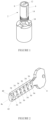
- FIG. 1 shows a lock cylinder 2 and Figure 2 shows a key 4 for operating the lock cylinder 2 in accordance with the invention.
- the lock cylinder 2 comprises a stator 6 of annular cross-section and a cylindrical rotor 8 that is received by and is a close sliding fit in the stator 6.
- a locking cam 10 is coupled to the rotor 8.
- the rotor 8 has an axially extending keyway 12 located eccentrically along a diameter of the rotor 8 for receiving the key 4.
- a row of six transverse passages 14 pass through the rotor 8 and stator 6 intersecting the keyway 12.
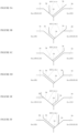
- Figures 3a to 3f show six pairs of locking pins, one for each of the passages 14 of the stator 6 and rotor 8 located in a release position by insertion of the matching key 4 in the keyway.
- Each pair comprises two pins selected from three different lengths of pins, nominally designated a No.1 pin, a No.2 pin and a No.3 pin.
- the No.1 pin is shorter than the No.2 pin which in turn is shorter than the No.3 pin.
- the six pin pairs consist of the following combinations of pins as viewed in Figures 3a to 3f :
- the reference to left side and right side pins are used for convenience to describe the pins as shown in the drawings and it will be understood the invention is not limited to such designation of the pins.
- the lengths of the pins are chosen so that the combined length of each pair is the same and is slightly less than the diameter of the rotor 8 so that, when the pin pair is located in the release position, both pins are located wholly within the rotor 8 so that the rotor 8 can rotate relative to the stator 6 to operate the lock cylinder 2.
- This may not be essential and combined pin lengths may not be the same provided that, in the release position, the pins are received within the rotor 8 and do not project across the interface between the rotor 8 and stator 6.
- No. 1 pins are indicated by reference numeral 16, No. 2 pins by reference numeral 18 and No. 3 pins by reference numeral 20.
- FIG 4 is a sectional view through the passage 14 of the stator 6 and rotor 8 showing a rest position of the No. 1 pin 16 and the No. 3 pin 20 of Figure 3a with the key 4 removed.
- the passage 14 has an abutment shoulder 14a at each interface with the keyway 12.
- Each pin 16, 20 has a tapered inner end portion 22 leading to an annular collar 24 slidably received in the passage 14 and is biased towards the keyway 12 by a spring 26, 28 that surrounds the pin 16, 20 and acts between the collar 24 and an annular ring 30 that slidably receives and supports an outer end portion 32 of the pin 16, 20.
- the springs 26, 28 bias the pins 16, 20 so that inner end faces 22a of the pins abut in the keyway 12.
- the spring 26 acting on the shorter pin 16 is stronger than the spring 28 acting on the longer pin 20 and exerts an extra force that overcomes the biasing of the weaker spring 28.
- the pair of pins 16, 20 is located at the rest position shown in Figure 4 , in which the outer end of the shorter pin 16 is located within the rotor 8 with the collar 24 seated against the abutment shoulder 14a and the outer end of the longer pin 20 projects across the interface between the rotor 8 and the stator 6 and is received in the stator 6 blocking rotation of the rotor 8 relative to the stator 6.
- the rotor 8 is unable to rotate relative to the stator 6 in the rest position of the pins 16, 20 with the key removed.
- Figure 5 is a sectional view through the passage 14 of the stator 6 and rotor 8 showing the release position of the No. 1 pin 16 and No. 3 pin 20 of Figure 3a with the correct key 4 inserted.
- the key 4 has a pair of opposed, interconnected tapered recesses 34, 36 and comprises a first recess 34 and a second recess 36 connected at an interface 38.
- the first recess 34 receives the tapered inner end portion 22 of the shorter pin 16 and is configured so that the shorter pin 16 is pushed back from its rest position in Figure 4 (from right to left as viewed in Figure 4 ) against the biasing of the spring 26 to the release position shown in Figure 5 in which the inner end portion 22 of the pin 16 is seated in the recess 34 and projects across the interface 38 between the recesses 34, 36.
- the longer pin 20 is allowed to advance from its rest position in Figure 4 (from right to left as viewed in Figure 4 ) under the biasing of the spring 28 to the release position shown in Figure 5 in which the inner end face 22a abuts the inner end face 22a of the shorter pin 16 without seating in the recess 36.
- the radial position of the pin 16 biased by the stronger spring 26 is determined by the depth of cut of the recess 34 in the key and the radial position of the pin 20 biased by the weaker spring 28 is determined by the position of the pin 16.
- the depth of the recess 34 has to be an accurate match to position the pin 16 in the release position but the depth of the recess 36 does not have to be an accurate match to position the pin 20 in the release position allowing the recess 36 to be cut oversize for a reason explained later.
- Figure 3b shows the release position for a No. 1 and a No. 3 pin pair similar to Figure 3a but with the biasing of the pins reversed so that now the longer, No. 3 pin 20 is biased by the stronger spring 26 and is seated in the matching recess 34 of the key 4 so as to locate the pin 20 in the release position with the shorter No. 1 pin 16 biased by the weaker spring 28 received in the oversize recess 36 of the key and located in the release position by the longer pin 20.
- the shorter pin 16 is displaced by the longer pin 20 so that the outer end of the shorter pin 16 projects across the interface between the rotor 8 and stator 6 to block rotation of the rotor relative to the stator.
- Figure 3c shows the release position for a pair of No. 2 pins of equal length with the left hand pin 18 as viewed in the Figure biased by the stronger pin 26 and seated in the matching recess 34 of the key 4 so as to locate the left hand pin 18 in the release position with the right hand pin 18 as viewed in the Figure biased by the weaker spring 28 received in the oversize recess 36 of the key and located in the release position by the left hand pin 18.
- Figure 3d shows the release position for a pair of No. 2 pins similar to Figure 3c but with the biasing of the pins reversed so that now the right hand pin 18 is biased by the stronger spring 26 and is seated in the matching recess 34 of the key 4 so as to locate the pin 18 in the release position with the left hand pin 18 biased by the weaker spring 28 received in the oversize recess 36 and located in the release position by the right hand pin 18.
- the left hand pin 18 is displaced by the right hand pin 18 so that the outer end of the left hand pin projects across the interface between the rotor 8 and stator 6 to block rotation of the rotor relative to the stator.
- Figure 3e shows the release position for a No. 3 and No. 1 pin pair similar to Figure 3b but with the position of the pins reversed.
- the longer pin 20 is biased by the stronger spring 26 and is seated in the matching recess 34 of the key 4 so as to locate the pin 20 in the release position with the shorter pin 16 biased by the weaker spring 28 received in the oversize recess 36 and located in the release position by the longer pin 20.
- the shorter pin 16 is displaced by the longer pin 20 so that the outer end of the shorter pin projects across the interface between the rotor 8 and stator 6 to block rotation of the rotor relative to the stator.
- Figure 3f shows the release position for a No. 3 and No. 1 pin pair similar to Figure 3e but with the biasing of the pins reversed so that now the shorter pin 16 is biased by the stronger spring 26 and is seated in the matching recess 34 of the key 4 so as to locate the pin 16 in the release position with the longer pin 20 biased by the weaker spring 28 received in the oversize recess and located in the release position by the shorter pin 16.
- the longer pin 20 is displaced by the shorter pin 16 so that the outer end of the longer pin 20 projects across the interface between the rotor 8 and stator 6 to block rotation of the rotor relative to the stator.
- FIG 2 shows the key 4 with a shank 4a having two rows 40, 42 of recesses 34, 36 configured to match the pin pairs of Figures 3a to 3f .
- the recess on the opposite side of the shank 4a is the same as the recess at the same position in the lower row 42 and vice versa. In this way, the key shank 4a can be inserted into the key-way 12 either way up. This may not be essential however and we may provide a key shank with one row of recesses.
- the interfaces 38 between the recesses 34, 36 in Figures 3c and 3d are on either side of the radial abutment position of the pins in the release position and the interfaces between the recesses in Figures 3e and 3f are on either side of the radial abutment position of the pins in the release position.
- the interfaces between the recesses for all six pairs of pins are offset relative to each other. In this way we can achieve 6 6 (46656) combinations with only three different pin lengths. Reducing the number of pin lengths in this way has advantages for manufacture and assembly of the lock cylinder 2 and can also lead to improved security as now explained.
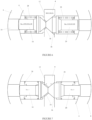
- Figure 6 shows a non-matching key and pin arrangement.
- the key has a recess arrangement to match the pin arrangement shown in Figure 3a with a recess 34 having an accurate depth of cut to locate the shorter No. 1 pin 16 biased by the stronger spring 26 in the release position and an oversize recess 36 for the longer No. 3 pin biased by the weaker spring 28 which is located in the release position by abutment with the pin 16.
- the pin arrangement is that shown in Figure 3b with the springs 26, 28 reversed so that now the longer No. 3 pin is biased by the stronger spring 26 and the shorter No. 1 pin 16 is biased by the weaker spring 28.
- the longer No. 3 pin is biased by the stronger spring 26 and the shorter No. 1 pin 16 is biased by the weaker spring 28.
- Figure 7 shows another non-matching key and pin arrangement.
- the key has a recess arrangement to match the pin arrangement shown in Figure 3c with a recess 34 having an accurate depth of cut to locate the left hand No. 2 pin 18 biased by the stronger spring 26 in the release position and an oversize recess 36 for the right hand No. 2 pin biased by the weaker spring 28 which is located in the release position by abutment with the left hand pin.
- the pin arrangement is that shown in Figure 3b with the longer No. 3 pin 20 biased by the stronger spring 26 and the shorter No. 1 pin 16 biased by the weaker spring 28.
- the recesses can configure the recesses to control the extent to which one of the pins of each pin pair projects across the interface between the rotor and stator when, for a given pin pair, the pin biased by the stronger spring is received in a non-matching recess of the key, i.e. when the recess does not have an accurate depth of cut to position the pin in the correct position. For example, cutting the oversize recess 36 in Figure 6 so that the longer No. 3 pin 20 can advance by 0.3 mm beyond the release position causes the shorter No. 1 pin 16 to be pushed back and project into the stator by the same distance.
- the groove 44 and lip 46 may have angled faces that increase the interlock to retain the pin in the blocking position if an attempt is made to turn the rotor with a non-matching key. Any suitable co-operating formations may be employed and it will be understood the arrangement is not limited to the lock cylinder of the present invention and may be employed in pin tumbler lock cylinders generally.
Landscapes
- Iron Core Of Rotating Electric Machines (AREA)
Abstract
A key operable lock cylinder in which a rotor 8 is mounted within a stator 6 for rotation about a longitudinal axis of the stator and a plurality of transverse passages 14 extend through the rotor 8 and stator 6 to intersect a keyway 12 extending axially into the rotor 8. Each passage 14 is provided with a pair of locking pins 16, 20 slidably mounted in the passage 14 and biased by respective springs 26, 28 to abut within the keyway 12. The spring of one pin of each pair of pins 16, 20 is stronger than the spring of the other pin and urges the other pin to project across an interface between the rotor 8 and stator 6 to prevent rotation of the rotor 8 relative to the stator 8 in a locked condition. The pins of each pair of pins 16, 20 are movable in response to insertion of a complementary key in the keyway 12 to become located entirely within the rotor 8 to permit rotation of the rotor 8 relative to the stator 6 in an unlocked condition. Two pairs of the same locking pins are provided in which the biasing of the pins by the springs in one pair is reversed in the other pair of the same pins. In this way, for a given number of pins, the number of available combinations can be increased.
Description
- This invention relates to an improvement in the design of locks. More specifically the present invention relates to improvements to pin-tumbler locks. The invention also relates to keys for use with such locks
A key-operable cylinder lock is known fromEP-A-0892130 comprising a rotor rotatably mounted within a stator and a plurality of pairs of locking pins located in transverse passages extending through the rotor and the stator. Each pin pair is biased to abut in a keyway in the rotor so that one of the pins projects across an interface between the rotor and stator when the key is removed to prevent rotation of the rotor. Preferably six pin pairs are provided with pins selected from five different pin lengths so that the combined length of the pins of each pin pair is substantially the same as the diameter of the rotor and the pins can be positioned entirely within the rotor when the matching key is inserted to allow the rotor to turn relative to the stator. With this arrangement the shorter pin of any pin pair is biased more strongly and the total number of combinations is 56 = 15625. - A desired aim of the present invention is to provide a key-operable lock cylinder in which the number of combinations may be increased without increasing the number of pin pairs employed.
- Another desired aim of the present invention is to provide a key-operable lock cylinder in which the number of combinations may be increased employing a reduced number of pin lengths.
- According to a first aspect of the invention there is provided a key operable lock cylinder comprising a stator, a rotor, the rotor being mounted within the stator for rotation about a longitudinal axis of the stator, a keyway extending axially into the rotor, a plurality of transverse passages extending through the rotor and stator and intersecting the keyway, each passage being provided with a pair of locking pins slidably mounted in the passage and biased by respective biasing means to abut within the keyway, the biasing means of one pin of each pair being stronger than the biasing means of the other pin and urging the other pin to project across an interface between the rotor and stator to prevent rotation of the rotor relative to the stator, the pins of each pair being movable in response to insertion of a complementary key in the keyway to become located entirely within the rotor to permit rotation of the rotor relative to the stator, wherein, for each pair of locking pins, another pair of the same locking pins is provided in which the biasing means is reversed.
- By providing more than one pair of locking pins with the same locking pins and reversing the biasing means, the number of available combinations may be increased with a reduction in the number of different pin lengths. Thus, in a lock cylinder in accordance with the invention, each pin of a pin pair may be used with a strong spring or a relatively weaker spring so providing two alternative combinations for each pin pair combination. As a result manufacture of the lock is simplified.
- In one preferred form, each pin pair comprises a pair of pins selected from three different lengths of pins. For convenience and by way of non-limiting example, the three different lengths of pins may be designated a No.1 pin, a No.2, and a No.3 where a No.1 pin is the shortest pin length, a No.3 pin is the longest pin length and a No.2 pin is an intermediate pin length between the No.1 pin and the No.3 pin.
- Preferably, the pin lengths are chosen so that the total length of a pin pair comprising a No.1 pin and a No.3 pin does not exceed the diameter of the rotor and is preferably substantially the same as the diameter of the rotor. Similarly, the total length of a pin pair comprising a No.2 pin and a No.2 pin does not exceed the diameter of the rotor and is preferably substantially the same as the diameter of the rotor.
- With three pin lengths and reversing the biasing, six combinations can be obtained and can be conveniently referred to as 1(st.):3, 1:3(st); 2(st):2, 2:2(st), 3(st):1, 3:1(st) where "st" indicates that the biasing means for the designated pin length of a given pin pair is relatively stronger than the biasing means for the other pin length of the pin pair.
- The biasing means for each pin may comprise a spring, for example a compression spring. The spring may act to urge the pin towards the keyway. A stop may be provided to limit movement of the pin under the biasing of the spring. The pin may have a tapered head that can assist insertion of a key in the keyway.
- Preferably, in a locked position, each pair of locking pins are in mutual abutment within the keyway with a distal end of one of the locking pins of each pair projecting across the interface between the rotor and the stator so as to prevent rotation of the rotor within the stator whereas in use, when a complementary key is inserted in the keyway, the locking pins are moveable so that all the locking pins become located entirely within the rotor permitting rotation of the rotor within the stator.
- Preferably, at least two pairs of locking pins are provided having the same combination of locking pins of different length with the resilient biasing means for the locking pins of one of the two pairs reversed for the locking pins of the other of the two pairs. In this way, the same combination of locking pins can produce two different pin pairs where the longer pin of one pin pair is more strongly biased and the shorter pin of the other pair is more strongly biased. This has the surprising advantage that, in a key operated lock cylinder in accordance with the invention, the number of pin lengths can be reduced while retaining a large number of combinations and in some cases the number of combinations may be larger than in a conventional arrangement having a greater number of different pin lengths.
- According to a second aspect of the invention there is provided a key for use with the lock cylinder of the first aspect of the invention, the key comprising a handle and a shank, the shank being received, in use, within a keyway of the lock cylinder, the shank having first and second major surfaces along its length on opposite sides, a row of recesses along its length on the first major surface and a row of recesses along its length on the second major surface so that the recesses on the first and second major surfaces are aligned in pairs such that, in use, each pair of aligned recesses can accommodate a pair of locking pins of the lock cylinder, wherein each pair of recesses is interconnected and configured so that, in use, when a correct key is inserted into the keyway, the pin biased by the stronger biasing means locates in the recess on one side of the shank and is pushed back against the biasing of the stronger biasing means by the key, and the other pin, biased by the weaker biasing means is located in an oversize recess on the other side of the shank by abutment with the more strongly biased pin so that both pins are located entirely within the rotor and do not project across the interface between the rotor and stator so that the rotor can be rotated relative to the stator, wherein for each pair of recesses, another pair of recesses is provided to accommodate a pair of the same locking pins of the lock cylinder in which the biasing means is reversed.
- In use, if an incorrect key is inserted, then the pin biased by the stronger biasing means is either pushed back too far by the key when it seats in the recess and projects across the interface with the stator or is not pushed back far enough so that the other pin is prevented from moving completely into the rotor and projects across the interface with the stator. In either situation one of the pins extends across the interface and the rotor is prevented from rotating relative to the stator.
- A particular advantage has been found in using the key with the lock cylinder in accordance with the first aspect of the invention wherein reducing the number of pin lengths enables the spacing between drops to be increased for a given thickness of key shank with the result that the extent to which the pin of any pin pair that projects across the interface to block rotation of the rotor in the locked condition may be increased and thereby improve security. For example, in a lock cylinder having five different pin lengths and a key shank thickness of 2.0 mm, the spacing between each drop is 0.33 mm, whereas in a lock cylinder in accordance with the first aspect of the invention having three different pin lengths, the spacing between each drop for the same key shank can be increased from 0.33 mm to 0.5 mm. As a result, we can configure the recesses to control the extent to which one of the pins of each pin pair projects across the interface between the rotor and stator when, for a given pin pair, the pin biased by the stronger spring is received in a non-matching recess of the key, i.e. when the recess does not have an accurate depth of cut to position the pin in the correct position. In this way, the overlap to block rotation of the rotor may be increased both when the blocking pin is the pin biased by the weaker biasing means so as to be located by abutment with the more strongly biased pin and when the blocking pin is the pin biased by the stronger biasing means.
- Preferably, the recesses of an aligned pair are of different depths and the position of the restriction relative to the first and second major surfaces of the shank varies from one pair to another pair. Preferably, for a given drop corresponding to a radial abutment position of a pin pair, two pairs of recesses are provided in which the position of the restriction of one pair relative to the first and second major surfaces of the shank is to one side of the drop and the position of the restriction of the other pair relative to the first and second major surfaces of the shank is to the other side of the drop. In this way, two cuts are provided for each drop.
- According to a third aspect of the invention there is provided in combination
- a lock cylinder comprising a stator having a rotor mounted within the stator for rotation about a longitudinal axis of the stator, the rotor having a keyway extending axially into the rotor, a series of transverse passages extending through the rotor and stator and intersecting in the keyway, a pair of locking pins being slidably mounted in each passage and being resiliently biased by a respective biasing means such that in a locked position each pair of locking pins are in mutual abutment within the keyway with a distal end of one of the locking pins of each pair projecting across an interface between the rotor and the stator so as to prevent rotation of the rotor within the stator whereas in use, when a complementary key is inserted in the keyway the locking pins are positioned such that all the locking pins become located entirely within the rotor permitting rotation of the rotor within the stator and wherein the key operable lock cylinder comprises at least a first pair of locking pins and a second pair of locking pins in which in each pair comprises a first pin having a first length and a second pin having a second length, the first length being the same in both pairs and the second length being the same in both pairs and longer than the first length, wherein the first pin of the first pair of pins is more strongly biased than the second pin and the second pin of the second pair of pins is more strongly biased than the first pin, and
- a key comprising a handle and a shank, the shank being arranged to fit in use within the keyway of the lock cylinder, the shank having first and second major faces, the first face having at least one row of recesses along its length and the second face having at least one row of recesses along its length aligned with the row of recesses on the first face, the aligned recesses on the first and second faces being interconnected such that locking pins of the lock cylinder can be accommodated in the recesses in use and wherein one of each pair of aligned recesses is oversized relative to the locking pin to be received in the recess.
- Preferably, when the matching key is inserted in the keyway, the more strongly biased pin of each pin pair seats in a matching recess in the key shank and the less strongly biased pin is received in the oversize recess and located by abutment with the more strongly biased pin.
- The key can have two cuts for two pin pairs having the same combination of locking pins by reversing the biasing of the locking pins and providing an oversize recess for the less strongly biased pin.
- Preferably, each pin pair is selected from three different pin lengths and the number of combinations is 66 (46656).
- Preferably, in the locked position, the locking pin projecting across the interface is provided with a formation co-operable with a formation on one of the stator and rotor to retain the pin in the locked position if a non-matching key inserted in the key-way is turned to rotate the rotor.
- Any suitable formations may be employed. The co-operating formations preferably interlock to retain a distal end of the locking pin in the stator when a non-matching key inserted in the keyway is turned to rotate the rotor. The interlock feature may be employed in the lock cylinder according to any of the preceding aspects of the invention.
- The invention will now be described by way of example only with reference to the accompanying drawings in which:
-
Figure 1 is a perspective view of a lock cylinder in accordance with the invention; -
Figure 2 is a perspective view, to an enlarged scale, of a key for operating the lock cylinder ofFigure 1 ; -
Figures 3a to 3f are part sectional views of six pin pairs of the lock cylinder shown inFigure 1 with the matching key inserted depicting the release positions of all the pin pairs; -
Figure 4 is a sectional view of the passage in the rotor and stator with the pin pair shown inFigure 3a and the key removed depicting a rest position of the pin pair; -
Figure 5 is a sectional view, similar toFigure 4 , with the matching key inserted depicting a release position of the pin pair; -
Figure 6 is a sectional view showing a non-matching key and pin pair arrangement; -
Figure 7 is a sectional view showing another non-matching key and pin pair arrangement; -
Figure 8 is a sectional view, to an enlarged scale, showing the spacing of drops in the key shank for different pin pairs; and -
Figure 9 is a sectional view showing a modification to a pin pair and stator of the lock cylinder ofFigure 1 . -
Figure 1 shows alock cylinder 2 andFigure 2 shows akey 4 for operating thelock cylinder 2 in accordance with the invention. Thelock cylinder 2 comprises astator 6 of annular cross-section and acylindrical rotor 8 that is received by and is a close sliding fit in thestator 6. Alocking cam 10 is coupled to therotor 8. Therotor 8 has an axially extendingkeyway 12 located eccentrically along a diameter of therotor 8 for receiving thekey 4. A row of sixtransverse passages 14 pass through therotor 8 andstator 6 intersecting thekeyway 12. -
Figures 3a to 3f show six pairs of locking pins, one for each of thepassages 14 of thestator 6 androtor 8 located in a release position by insertion of the matchingkey 4 in the keyway. Each pair comprises two pins selected from three different lengths of pins, nominally designated a No.1 pin, a No.2 pin and a No.3 pin. The No.1 pin is shorter than the No.2 pin which in turn is shorter than the No.3 pin. The six pin pairs consist of the following combinations of pins as viewed inFigures 3a to 3f : The reference to left side and right side pins are used for convenience to describe the pins as shown in the drawings and it will be understood the invention is not limited to such designation of the pins.Left Side Pin Right Side Pin Figure No. 1 pin No. 3 pin Figure 3a No. 1 pin No. 3 pin Figure 3b No. 2 pin No. 2 pin Figure 3c No. 2 pin No. 2 pin Figure 3d No. 3 pin No. 1 pin Figure 3e No. 3 pin No. 1 pin Figure 3f - The lengths of the pins are chosen so that the combined length of each pair is the same and is slightly less than the diameter of the
rotor 8 so that, when the pin pair is located in the release position, both pins are located wholly within therotor 8 so that therotor 8 can rotate relative to thestator 6 to operate thelock cylinder 2. This may not be essential and combined pin lengths may not be the same provided that, in the release position, the pins are received within therotor 8 and do not project across the interface between therotor 8 andstator 6. For convenience, in the following description No. 1 pins are indicated byreference numeral 16, No. 2 pins byreference numeral 18 and No. 3 pins byreference numeral 20. -
Figure 4 is a sectional view through thepassage 14 of thestator 6 androtor 8 showing a rest position of the No. 1pin 16 and the No. 3pin 20 ofFigure 3a with the key 4 removed. Thepassage 14 has anabutment shoulder 14a at each interface with thekeyway 12. Eachpin inner end portion 22 leading to anannular collar 24 slidably received in thepassage 14 and is biased towards thekeyway 12 by aspring pin collar 24 and anannular ring 30 that slidably receives and supports anouter end portion 32 of thepin springs pins keyway 12. Thespring 26 acting on theshorter pin 16 is stronger than thespring 28 acting on thelonger pin 20 and exerts an extra force that overcomes the biasing of theweaker spring 28. As a result, the pair ofpins Figure 4 , in which the outer end of theshorter pin 16 is located within therotor 8 with thecollar 24 seated against theabutment shoulder 14a and the outer end of thelonger pin 20 projects across the interface between therotor 8 and thestator 6 and is received in thestator 6 blocking rotation of therotor 8 relative to thestator 6. As a result, therotor 8 is unable to rotate relative to thestator 6 in the rest position of thepins -
Figure 5 is a sectional view through thepassage 14 of thestator 6 androtor 8 showing the release position of the No. 1pin 16 and No. 3pin 20 ofFigure 3a with thecorrect key 4 inserted. Thekey 4 has a pair of opposed, interconnected taperedrecesses first recess 34 and asecond recess 36 connected at aninterface 38. Thefirst recess 34 receives the taperedinner end portion 22 of theshorter pin 16 and is configured so that theshorter pin 16 is pushed back from its rest position inFigure 4 (from right to left as viewed inFigure 4 ) against the biasing of thespring 26 to the release position shown inFigure 5 in which theinner end portion 22 of thepin 16 is seated in therecess 34 and projects across theinterface 38 between therecesses longer pin 20 is allowed to advance from its rest position inFigure 4 (from right to left as viewed inFigure 4 ) under the biasing of thespring 28 to the release position shown inFigure 5 in which theinner end face 22a abuts theinner end face 22a of theshorter pin 16 without seating in therecess 36. In the release position, the outer ends of bothpins rotor 8 allowing rotation of therotor 8 relative to thestator 6. As a result, therotor 8 is free to rotate relative to thestator 6 in the release position of thepins correct key 4 inserted in thekeyway 12. - As will be appreciated, in the release position of
Figure 5 , the radial position of thepin 16 biased by thestronger spring 26 is determined by the depth of cut of therecess 34 in the key and the radial position of thepin 20 biased by theweaker spring 28 is determined by the position of thepin 16. As a result, the depth of therecess 34 has to be an accurate match to position thepin 16 in the release position but the depth of therecess 36 does not have to be an accurate match to position thepin 20 in the release position allowing therecess 36 to be cut oversize for a reason explained later. -
Figure 3b shows the release position for a No. 1 and a No. 3 pin pair similar toFigure 3a but with the biasing of the pins reversed so that now the longer, No. 3pin 20 is biased by thestronger spring 26 and is seated in thematching recess 34 of the key 4 so as to locate thepin 20 in the release position with the shorter No. 1pin 16 biased by theweaker spring 28 received in theoversize recess 36 of the key and located in the release position by thelonger pin 20. With this pin pair, when the key is removed, theshorter pin 16 is displaced by thelonger pin 20 so that the outer end of theshorter pin 16 projects across the interface between therotor 8 andstator 6 to block rotation of the rotor relative to the stator. -
Figure 3c shows the release position for a pair of No. 2 pins of equal length with theleft hand pin 18 as viewed in the Figure biased by thestronger pin 26 and seated in thematching recess 34 of the key 4 so as to locate theleft hand pin 18 in the release position with theright hand pin 18 as viewed in the Figure biased by theweaker spring 28 received in theoversize recess 36 of the key and located in the release position by theleft hand pin 18. With this pin pair, when the key is removed, theright hand pin 18 is displaced by theleft hand pin 18 so that the outer end of the right hand pin projects across the interface between therotor 8 andstator 6 to block rotation of the rotor relative to the stator. -
Figure 3d shows the release position for a pair of No. 2 pins similar toFigure 3c but with the biasing of the pins reversed so that now theright hand pin 18 is biased by thestronger spring 26 and is seated in thematching recess 34 of the key 4 so as to locate thepin 18 in the release position with theleft hand pin 18 biased by theweaker spring 28 received in theoversize recess 36 and located in the release position by theright hand pin 18. With this pin pair, when the key is removed, theleft hand pin 18 is displaced by theright hand pin 18 so that the outer end of the left hand pin projects across the interface between therotor 8 andstator 6 to block rotation of the rotor relative to the stator. -
Figure 3e shows the release position for a No. 3 and No. 1 pin pair similar toFigure 3b but with the position of the pins reversed. As inFigure 3b thelonger pin 20 is biased by thestronger spring 26 and is seated in thematching recess 34 of the key 4 so as to locate thepin 20 in the release position with theshorter pin 16 biased by theweaker spring 28 received in theoversize recess 36 and located in the release position by thelonger pin 20. With this pin pair, when the key is removed, theshorter pin 16 is displaced by thelonger pin 20 so that the outer end of the shorter pin projects across the interface between therotor 8 andstator 6 to block rotation of the rotor relative to the stator. -
Figure 3f shows the release position for a No. 3 and No. 1 pin pair similar toFigure 3e but with the biasing of the pins reversed so that now theshorter pin 16 is biased by thestronger spring 26 and is seated in thematching recess 34 of the key 4 so as to locate thepin 16 in the release position with thelonger pin 20 biased by theweaker spring 28 received in the oversize recess and located in the release position by theshorter pin 16. With this pin pair, when the key is removed, thelonger pin 20 is displaced by theshorter pin 16 so that the outer end of thelonger pin 20 projects across the interface between therotor 8 andstator 6 to block rotation of the rotor relative to the stator. - As will be appreciated, for each of the six pin pairs shown in
Figures 3a to 3f , the pin biased by thestronger spring 26 is radially located in the release position by the key and the pin biased by theweaker spring 28 is radially located in the release position by the pin biased by thestronger spring 26.Figure 2 shows the key 4 with ashank 4a having tworows recesses Figures 3a to 3f . For each recess in theupper row 40 as seen inFigure 2 the recess on the opposite side of theshank 4a is the same as the recess at the same position in thelower row 42 and vice versa. In this way, thekey shank 4a can be inserted into the key-way 12 either way up. This may not be essential however and we may provide a key shank with one row of recesses. - By reversing the biasing of the pin pairs for the same arrangement of pins in
Figures 3a and 3b, Figures 3c and 3d, and Figures 3e and 3f , and cutting an oversize recess for the pin biased by the weaker spring we can achieve a different depth of cut for the recesses of each pin pair using only three different pin lengths. More specifically, with reference toFigures 3a and 3b , although the same arrangement of pins is employed and the pins of both pairs abut at the same radial position in the release position, by reversing the biasing and cutting an oversize recess for the pin biased by the weaker spring, theinterface 38 between therecesses Figure 3a is offset to one side of the radial abutment position of the pins and theinterface 38 between therecesses Figure 3b is offset to the other side of the radial abutment position producing two key cuts for the same arrangement of pins. Similarly, theinterfaces 38 between therecesses Figures 3c and 3d are on either side of the radial abutment position of the pins in the release position and the interfaces between the recesses inFigures 3e and 3f are on either side of the radial abutment position of the pins in the release position. Moreover, the interfaces between the recesses for all six pairs of pins are offset relative to each other. In this way we can achieve 66 (46656) combinations with only three different pin lengths. Reducing the number of pin lengths in this way has advantages for manufacture and assembly of thelock cylinder 2 and can also lead to improved security as now explained. -
Figure 6 shows a non-matching key and pin arrangement. The key has a recess arrangement to match the pin arrangement shown inFigure 3a with arecess 34 having an accurate depth of cut to locate the shorter No. 1pin 16 biased by thestronger spring 26 in the release position and anoversize recess 36 for the longer No. 3 pin biased by theweaker spring 28 which is located in the release position by abutment with thepin 16. As shown inFigure 6 , the pin arrangement is that shown inFigure 3b with thesprings stronger spring 26 and the shorter No. 1pin 16 is biased by theweaker spring 28. As a result, when the key is inserted, the longer No. 3 pin now seats in theoversize recess 36 and the shorter No. 1pin 16 is located by abutment with thepin 20. However as therecess 36 does not have an accurate depth of cut for a No. 3 pin, thepin 20 is not located at the correct position and the shorter No. 1pin 16 is prevented from reaching the release position determined by the accurate depth of cut of therecess 34. As a result, the outer end of the shorter No. 1 pin projects across the interface between therotor 8 andstator 6 to block rotation of the rotor relative to the stator. -
Figure 7 shows another non-matching key and pin arrangement. The key has a recess arrangement to match the pin arrangement shown inFigure 3c with arecess 34 having an accurate depth of cut to locate the left hand No. 2pin 18 biased by thestronger spring 26 in the release position and anoversize recess 36 for the right hand No. 2 pin biased by theweaker spring 28 which is located in the release position by abutment with the left hand pin. As shown inFigure 7 , the pin arrangement is that shown inFigure 3b with the longer No. 3pin 20 biased by thestronger spring 26 and the shorter No. 1pin 16 biased by theweaker spring 28. As a result, when the key is inserted, the longer No. 3pin 20 now seats in theoversize recess 36 and the shorter No. 1pin 16 is located by abutment with thepin 20. However as therecess 36 does not have an accurate depth of cut for a No. 3 pin, thepin 20 is prevented from reaching the release position. As a result, the outer end of the longer No. 3 pin projects across the interface between therotor 8 andstator 6 to block rotation of the rotor relative to the stator. - As previously explained, we can achieve a large number of combinations (66 = 46656) with three different pin lengths. As a result, we can increase the drop between different pin pairs (1:3; 2:2; 3:1) for a given thickness (T) of key shank. For example, with a
key shank 4a having a typical thickness (T) of 2mm shown inFigure 8 and pin pairs selected from three pin lengths, we can space the release positions indicated (a), (b) and (c) for different pin pairs (1:3;2:2;3:1) byT\ 4 or 0.5 mm. As a result, we can configure the recesses to control the extent to which one of the pins of each pin pair projects across the interface between the rotor and stator when, for a given pin pair, the pin biased by the stronger spring is received in a non-matching recess of the key, i.e. when the recess does not have an accurate depth of cut to position the pin in the correct position. For example, cutting theoversize recess 36 inFigure 6 so that the longer No. 3pin 20 can advance by 0.3 mm beyond the release position causes the shorter No. 1pin 16 to be pushed back and project into the stator by the same distance. As a result, a significant overlap can be achieved to block rotation of the rotor and reduce the risk of thepin 16 being displaced to allow the rotor to turn despite only being held in the blocking position by the biasing of thespring 26 acting on thepin 20. Similarly, cutting theoversize recess 36 inFigure 7 so that the longer No. 3 is prevented by the key from reaching the release position by 0.2 mm causes the longer No. 3 pin to project into the stator by the same distance. Although the overlap is slightly less than inFigure 6 , because the pin providing the overlap is now located by the key as opposed to spring force as inFigure 6 , an overlap of 0.2 mm is sufficient to block rotation of the rotor with the key preventing displacement of thepin 20 to allow the rotor to turn. It will be understood that the above dimensions are provided by way of non-limiting example only and that variations from these dimensions are envisaged and within the scope of the invention while still providing the benefits and advantages discussed herein. - It will be understood the invention is not limited to the embodiment above-described. For example in a modification shown in
Figure 9 in which like reference numerals are used to indicate parts corresponding to the previous embodiment, we may provide thestator 6 and the outer end portion of a pin received in thestator 6 in the blocking position when a non-matching key is inserted in the keyway with formations that cooperate to provide mechanical interlock if an attempt is made to turn the rotor that prevents the pin being displaced from its blocking position into the rotor. As shown inFigure 9 , we may provide anannular groove 44 in the outer end portion of the pin that receives aninternal lip 46 at the outer end of the passage in thestator 6 when an attempt is made to turn the rotor that resists axial movement of the pin. Thegroove 44 andlip 46 may have angled faces that increase the interlock to retain the pin in the blocking position if an attempt is made to turn the rotor with a non-matching key. Any suitable co-operating formations may be employed and it will be understood the arrangement is not limited to the lock cylinder of the present invention and may be employed in pin tumbler lock cylinders generally. - Other modifications will be apparent to those skilled in the art.
Claims (15)
- A key operable lock cylinder comprising:a stator,a rotor,the rotor being mounted within the stator for rotation about a longitudinal axis of the stator,a keyway extending axially into the rotor,a plurality of transverse passages extending through the rotor and stator and intersecting the keyway,each passage being provided with a pair of locking pins slidably mounted in the passage and biased by respective biasing means to abut within the keyway,the biasing means of one pin of each pair being stronger than the biasing means of the other pin and urging the other pin to project across an interface between the rotor and stator to prevent rotation of the rotor relative to the stator,the pins of each pair being movable in response to insertion of a complementary key in the keyway to become located entirely within the rotor to permit rotation of the rotor relative to the stator,wherein, for each pair of locking pins, another pair of the same locking pins is provided in which the biasing means is reversed.
- The lock cylinder of claim 1 wherein each pair of locking pins comprises two pins selected from three different lengths of pins.
- The lock cylinder of claim 2 wherein a first pair of locking pins is provided having two locking pins of different length and a second pair of locking pins is provided having the same two locking pins as the first pair and the resilient biasing means for the locking pins of one of said two pairs is reversed for the locking pins of the other of said two pairs.
- The lock cylinder of claim 2 or claim 3 wherein six pairs of locking pins are provided.
- The lock cylinder of any preceding claim wherein the biasing means for each pin comprises a compression spring.
- The lock cylinder of claim 5 wherein each spring acts to urge the associated pins towards the keyway and a stop is provided to limit movement of the pin under the biasing of the spring.
- A key for use with the lock cylinder of claim 1, the key comprising a handle and a shank, the shank being received, in use, within a keyway of the lock cylinder, the shank having first and second major surfaces along its length on opposite sides, a row of recesses along its length on the first major surface and a row of recesses along its length on the second major surface so that the recesses on the first and second major surfaces are aligned in pairs such that, in use, each pair of aligned recesses can accommodate a pair of locking pins of the lock cylinder, wherein each pair of recesses is interconnected and configured so that, in use, when a correct key is inserted into the keyway, the pin biased by the stronger biasing means locates in the recess on one side of the shank and is pushed back against the biasing of the stronger biasing means by the key, and the other pin, biased by the weaker biasing means is located in an oversize recess on the other side of the shank by abutment with the more strongly biased pin so that both pins are located entirely within the rotor and do not project across the interface between the rotor and stator so that the rotor can be rotated relative to the stator, wherein for each pair of recesses, another pair of recesses is provided to accommodate a pair of the same locking pins of the lock cylinder in which the biasing means is reversed .
- A key according to claim 7 wherein for a given thickness (T) of the key shank, the spacing between drops between the first and second major surfaces for three different pin lengths is T/4.
- A key according to claim 7 or claim 8 wherein, the recesses of an aligned pair are of different depths and the position of the restriction relative to the first and second major surfaces of the shank varies from one pair to another pair, and, optionally, wherein, for a given drop corresponding to a radial abutment position of a pin pair, two pairs of recesses are provided in which the position of the restriction of one pair relative to the first and second major surfaces of the shank is to one side of the drop and the position of the restriction of the other pair relative to the first and second major surfaces of the shank is to the other side of the drop.
- The combination of a lock cylinder and a key,the lock cylinder comprising a stator having a rotor mounted within the stator for rotation about a longitudinal axis of the stator, the rotor having a keyway extending axially into the rotor, a series of transverse passages extending through the rotor and stator and intersecting in the keyway, a pair of locking pins being slidably mounted in each passage and being resiliently biased by a respective biasing means such that in a locked position each pair of locking pins are in mutual abutment within the keyway with a distal end of one of the locking pins of each pair projecting across an interface between the rotor and the stator so as to prevent rotation of the rotor within the stator whereas in use, when a complementary key is inserted in the keyway the locking pins are positioned such that all the locking pins become located entirely within the rotor permitting rotation of the rotor within the stator and wherein the key operable lock cylinder comprises at least a first pair of locking pins and a second pair of locking pins in which each pair comprises a first pin having a first length and a second pin having a second length, the first length being the same in both pairs and the second length being the same in both pairs and longer than the first length, wherein the first pin of the first pair of pins is more strongly biased than the second pin and the second pin of the second pair of pins is more strongly biased than the first pin, andthe key comprising a handle and a shank, the shank being arranged to fit in use within the keyway of the lock cylinder, the shank having first and second major faces, the first face having at least one row of recesses along its length and the second face having at least one row of recesses along its length aligned with the row of recesses on the first face, the aligned recesses on the first and second faces being interconnected such that locking pins of the lock cylinder can be accommodated in the recesses in use and wherein one of each pair of aligned recesses is oversized relative to the locking pin to be received in the recess.
- The combination of claim 10 wherein, when the matching key is inserted in the keyway, the more strongly biased pin of each pin pair seats in a matching recess in the key shank and the less strongly biased pin is received in the oversize recess and located by abutment with the more strongly biased pin.
- The combination of claim 11 wherein the key has two cuts for the same pair of pins by reversing the biasing of the first and second pairs of locking pins and providing an oversize recess for the less strongly biased pin.
- The combination of claim 11 or claim 12 wherein each pin pair is selected from three different pin lengths and the number of combinations is 66.
- The combination of any of claims 10 to 13 wherein, if an incorrect key is inserted, then the pin biased by the stronger biasing means is either pushed back too far by the key when it seats in the recess and projects across the interface with the stator or is not pushed back far enough so that the other pin is prevented from moving completely into the rotor and projects across the interface with the stator.
- The combination of any of claims 10 to 14 wherein, in the locked position, the locking pin projecting across the interface is provided with a formation co-operable with a formation on one of the stator and rotor to retain the pin in the locked position if a non-matching key inserted in the key-way is turned to rotate the rotor, and, optionally, wherein, the co-operating formations interlock to retain a distal end of the locking pin in the stator when a non-matching key inserted in the keyway is turned to rotate the rotor.
Applications Claiming Priority (1)
| Application Number | Priority Date | Filing Date | Title |
|---|---|---|---|
| GB2307969.2A GB2630395B (en) | 2023-05-26 | 2023-05-26 | Lock cylinder and key |
Publications (1)
| Publication Number | Publication Date |
|---|---|
| EP4474601A1 true EP4474601A1 (en) | 2024-12-11 |
Family
ID=87060746
Family Applications (1)
| Application Number | Title | Priority Date | Filing Date |
|---|---|---|---|
| EP24177260.7A Pending EP4474601A1 (en) | 2023-05-26 | 2024-05-22 | Lock cylinder and key |
Country Status (2)
| Country | Link |
|---|---|
| EP (1) | EP4474601A1 (en) |
| GB (1) | GB2630395B (en) |
Citations (2)
| Publication number | Priority date | Publication date | Assignee | Title |
|---|---|---|---|---|
| EP0892130A2 (en) | 1997-07-18 | 1999-01-20 | Brian Cowper | Lock cylinder |
| WO2017067096A1 (en) * | 2015-10-23 | 2017-04-27 | 梁敬彤 | Pin tumbler lock |
Family Cites Families (1)
| Publication number | Priority date | Publication date | Assignee | Title |
|---|---|---|---|---|
| GB2488783B (en) * | 2011-03-07 | 2013-05-01 | Banham Patent Locks Ltd | Lock cylinder & key therefor |
-
2023
- 2023-05-26 GB GB2307969.2A patent/GB2630395B/en active Active
-
2024
- 2024-05-22 EP EP24177260.7A patent/EP4474601A1/en active Pending
Patent Citations (2)
| Publication number | Priority date | Publication date | Assignee | Title |
|---|---|---|---|---|
| EP0892130A2 (en) | 1997-07-18 | 1999-01-20 | Brian Cowper | Lock cylinder |
| WO2017067096A1 (en) * | 2015-10-23 | 2017-04-27 | 梁敬彤 | Pin tumbler lock |
Also Published As
| Publication number | Publication date |
|---|---|
| GB2630395A (en) | 2024-11-27 |
| GB2630395B (en) | 2025-05-28 |
| GB202307969D0 (en) | 2023-07-12 |
Similar Documents
| Publication | Publication Date | Title |
|---|---|---|
| US5475998A (en) | Lock assembly with locking bar | |
| EP0605932B1 (en) | Locking apparatus | |
| EP1492929B1 (en) | Pin tumbler lock with a discriminating mechanism | |
| US8621902B2 (en) | Master keying system and method for programmable lock cylinder assemblies | |
| EP2084351B1 (en) | Rekeyable lock assembly and method of operation | |
| AU2008266989B2 (en) | Programmable lock cylinder assembly | |
| US6584819B1 (en) | Lock with two layers of lock mechanism | |
| EP2360333B1 (en) | Improved lock cylinder & key therefor | |
| US20090031774A1 (en) | Rekeyable lock cylinder | |
| US11359405B2 (en) | Double bitted-reversible key plug lock | |
| US10087654B2 (en) | Cylinder lock | |
| MXPA03007679A (en) | High security cylinder lock and key. | |
| US11988017B2 (en) | Key blank and key for actuating a disk cylinder and method of manufacturing such a key blank and key | |
| US10995521B2 (en) | Linear lock | |
| EP4474601A1 (en) | Lock cylinder and key | |
| US7181941B2 (en) | Lock system with improved auxiliary pin tumbler stack | |
| TW445338B (en) | Key for security cylinder, security cylinder, and bolt or lock equipped with a cylinder | |
| GB2632568A (en) | Lock cylinder and key | |
| EP0892130B1 (en) | Lock cylinder | |
| EP2497882B1 (en) | Lock cylinder and key therefor | |
| EP1752601A2 (en) | Reprogrammable lock | |
| TW202511589A (en) | Inverted blocker rack and pinion | |
| EP4158140A1 (en) | Lock and related key | |
| HK1001568B (en) | Locking apparatus | |
| HK1015846B (en) | Lock cylinder |
Legal Events
| Date | Code | Title | Description |
|---|---|---|---|
| PUAI | Public reference made under article 153(3) epc to a published international application that has entered the european phase |
Free format text: ORIGINAL CODE: 0009012 |
|
| STAA | Information on the status of an ep patent application or granted ep patent |
Free format text: STATUS: REQUEST FOR EXAMINATION WAS MADE |
|
| 17P | Request for examination filed |
Effective date: 20240522 |
|
| AK | Designated contracting states |
Kind code of ref document: A1 Designated state(s): AL AT BE BG CH CY CZ DE DK EE ES FI FR GB GR HR HU IE IS IT LI LT LU LV MC ME MK MT NL NO PL PT RO RS SE SI SK SM TR |