EP4474545A1 - Gripper weaving loom equipped with a diagnostic device of the gripper driving group - Google Patents
Gripper weaving loom equipped with a diagnostic device of the gripper driving group Download PDFInfo
- Publication number
- EP4474545A1 EP4474545A1 EP24176867.0A EP24176867A EP4474545A1 EP 4474545 A1 EP4474545 A1 EP 4474545A1 EP 24176867 A EP24176867 A EP 24176867A EP 4474545 A1 EP4474545 A1 EP 4474545A1
- Authority
- EP
- European Patent Office
- Prior art keywords
- gripper
- diagnostic device
- weaving loom
- driving group
- toothed wheel
- Prior art date
- Legal status (The legal status is an assumption and is not a legal conclusion. Google has not performed a legal analysis and makes no representation as to the accuracy of the status listed.)
- Granted
Links
Images


Classifications
-
- D—TEXTILES; PAPER
- D03—WEAVING
- D03D—WOVEN FABRICS; METHODS OF WEAVING; LOOMS
- D03D47/00—Looms in which bulk supply of weft does not pass through shed, e.g. shuttleless looms, gripper shuttle looms, dummy shuttle looms
- D03D47/27—Drive or guide mechanisms for weft inserting
- D03D47/275—Drive mechanisms
-
- D—TEXTILES; PAPER
- D03—WEAVING
- D03D—WOVEN FABRICS; METHODS OF WEAVING; LOOMS
- D03D47/00—Looms in which bulk supply of weft does not pass through shed, e.g. shuttleless looms, gripper shuttle looms, dummy shuttle looms
- D03D47/27—Drive or guide mechanisms for weft inserting
- D03D47/275—Drive mechanisms
- D03D47/276—Details or arrangement of sprocket wheels
-
- D—TEXTILES; PAPER
- D03—WEAVING
- D03D—WOVEN FABRICS; METHODS OF WEAVING; LOOMS
- D03D51/00—Driving, starting, or stopping arrangements; Automatic stop motions
- D03D51/18—Automatic stop motions
- D03D51/44—Automatic stop motions acting on defective operation of loom mechanisms
Definitions
- the present invention refers to a gripper weaving loom equipped with a diagnostic device of the gripper driving group.
- the invention refers to a diagnostic device capable of signalling, in a gripper weaving loom, possible mechanical malfunctions or incorrect adjustments of mechanical components of the gripper driving group.
- Said toothed wheels cause in turn the reciprocating rectilinear movement of the above-mentioned grippers - from the outside to the centre of the warp shed, where the exchange of the weft thread between the carrying gripper and the drawing gripper takes place, and vice versa - through a pair of flexible straps provided with a series of axial slots which are kept engaged on a sector of said toothed wheels and then guided inside the shed by means of suitable guide means.
- the continuous circular movement of the weaving loom main motor is transformed into a reciprocating rectilinear movement of the grippers by means of a mobile coupling between a sliding-block cursor, which is driven in reciprocating rectilinear movement by the loom main motor by means of a rod/crank mechanism, and a variable-pitch worm screw, free to rotate on support bearings.
- Said variable-pitch worm screw is driven in a reciprocating rotary movement by said sliding-block cursor, wherein pairs of opposite sliding-blocks are housed in a respective sliding-block holder element which is idle-hinged to said sliding-block cursor.
- a toothed wheel keyed to one end of said worm screw drives the movement of a flexible strap to the end of which one of the loom grippers is fixed as indicated above.
- gripper driving group or, more generically, driving group of the weft transfer - must be carefully maintained to prevent any malfunctions or failure to its individual mechanical components, or any incorrect adjustments of the same which, if not promptly put right, could cause weaving errors or more serious and extensive failure to the gripper driving group.
- the components subject to malfunctions are those subject to wear and/or alternating variable loads such as, in particular, support bearings of rotating shafts and mechanical joints of different types between said components, which may be subject to formation of unwanted plays or to structural failures.
- JP2000096388 discloses a gripper weaving loom having a gripper driving group as described above and further comprising a detection device positioned near the gripper strap, in the area where the gripper strap winds around a sector of the toothed wheel, to detect the degree of flexure of the gripper strap in the operation of the gripper loom. When the degree of flexure overcomes a specified limit, a warning signal is sent to a loom control device.
- the general structure disclosed in this document is also used by the pre-sent invention, although to an entirely different purpose, and the above features are therefore comprised in the preamble of the main claim of the invention.
- the technical problem addressed by the present invention is therefore to provide a diagnostic device capable of continuously monitoring the performance of the gripper driving group and reporting any possible malfunctions thereof, without interfering with the regular operation of such gripper driving group, and thus during the regular running of the weaving loom.
- a first object of the present invention is to identify a component of the gripper driving group which can serve as a sufficiently sensitive "sentinel" of a possible malfunction of any one of the gripper driving group critical components indicated above on the one hand, and which is accessible enough to be continuously monitored, preferably without direct contact, while the weaving loom is running, on the other hand.
- a second object of the invention is to provide a diagnostic device which is capable of carrying out continuous monitoring of the "sentinel" component indicated above, automatically detecting possible operating anomalies and correlating said operating anomalies with malfunctions of specific components of the gripper driving group, in order to guide the operator to one or more gripper driving group components where a malfunction is more likely to have occurred and whereon therefore a maintenance, adjustment or replacement intervention must be carried out.
- a third object of the invention is to provide a diagnostic device capable of detecting even minimal operating anomalies of the "sentinel" component indicated above, without being influenced by dust and by the variability of environmental conditions of lighting, temperature, and humidity, meanwhile offering a high degree of precision, repeatability and reliability in the performed measurements, and a complete absence of interference with the monitored component.
- the Applicant first identified the toothed wheel, and particularly its toothed crown (hereinafter also simply referred to as “crown”), as the more promising “sentinel” component of the gripper driving group for detecting any malfunctions of the other components of said gripper driving group.
- the toothed wheel is in fact the last component of the kinematic chain of the gripper driving group and it is rigidly connected to a relative support shaft, so that any possible malfunction of the other components of the gripper driving group, upstream of the toothed wheel, inevitably results in a corresponding anomaly in the toothed wheel movement.
- the very presence of the teeth is a convenient element for indexing the detection along the perimeter of the toothed wheel and therefore with respect to the loom work cycle.
- the toothed wheel crown, or at least one portion thereof is easily accessible for placing a sensing device in the sector of the toothed wheel which is not engaged by the flexible strap.
- a dedicated toothed crown can also be used for this purpose, integral with the same support shaft of the toothed wheel, where this option is more effective or convenient in view of the positioning of the toothed wheel or the material it is made of.
- the movement of the toothed wheel should be detected using detection devices which have a high precision and accuracy, for example detection devices provided with high-grade optical or electronic sensors available on the market, so as to detect any possible anomaly in the toothed wheel movement, such as for example eccentric rotations or phase variations.
- an "electronic profile" of the toothed wheel toothing can be obtained, which reproduces - in a qualitative but highly representative way of the actual condition - the physical profile of the toothed crown.
- a series of experimental tests using the detection device described above made it possible to verify that each malfunction of a specific component of the gripper driving group actually corresponds to a well-defined configuration of the electronic profile of the toothed wheel crown. It was therefore possible to set up a series of algorithms for analysing said electronic profile, each of them allowing to promptly detect the onset of one of these specific configurations of the electronic profile.
- the diagnostic device control software which incorporates such analysis algorithms, activates a corresponding warning signal which addresses the operator to check one or more components of the gripper driving group, and/or immediately stops the loom operation when a malfunction related to the detected electronic profile configuration implies a possible imminent failure of a component.
- Maintenance, adjustment or replacement operations can thus be carried out only on those components for which a possible malfunction has been warned, with a notable increase in effectiveness both in terms of reducing the time required to identify the failure which caused the profile anomaly, and because the anomaly is detected at a very early stage and therefore before the failure of that component could cause any failure to the other components or to the fabric being processed, and finally also because a maintenance, adjustment or replacement intervention of the components of the gripper driving group can be postponed, with respect to the times prescribed by the scheduled periodic maintenance, until some specific anomaly is detected in the electronic profile of the toothed wheel crown, thus allowing the useful life of such components to be significantly extended without compromising the operational safety of the gripper driving group.
- the Applicant has developed a particular device for magnetic detection of the toothed profile of the toothed wheels which control the grippers, illustrated in Fig. 5 , based on the use of a magnet and a magnetometer M - such as for example a Hall effect sensor - installed at a known distance in the proximity of the toothed crown C of a toothed wheel D of a gripper driving group G.
- a magnet and a magnetometer M - such as for example a Hall effect sensor - installed at a known distance in the proximity of the toothed crown C of a toothed wheel D of a gripper driving group G.
- the magnetometer M detects a variable magnetic field - determined by the constant magnetic field induced by the permanent magnet, as modified by the ferromagnetic material of the moving toothed wheel D - having a higher value at the teeth tips and a lower value at the bottom of the space between two successive teeth, the detected magnetic field being approximately proportional to the distance between the teeth profile and the magnetometer M.
- This detection device made it possible to carry out a particularly accurate detection of the anomalies in the toothed wheel D movement.
Landscapes
- Engineering & Computer Science (AREA)
- Textile Engineering (AREA)
- Looms (AREA)
- Testing Of Devices, Machine Parts, Or Other Structures Thereof (AREA)
Abstract
Description
- The present invention refers to a gripper weaving loom equipped with a diagnostic device of the gripper driving group. In particular, the invention refers to a diagnostic device capable of signalling, in a gripper weaving loom, possible mechanical malfunctions or incorrect adjustments of mechanical components of the gripper driving group.
- As known, in gripper weaving looms there are gripper driving groups which drive the reciprocating rectilinear movement of the carrying gripper and the drawing gripper, by transforming through appropriate kinematics the rotary movement of the weaving loom main motor into an alternate rotary movement of a pair of toothed wheels, keyed to a respective shaft parallel to the warp and placed one on each side of the weaving loom. Said toothed wheels cause in turn the reciprocating rectilinear movement of the above-mentioned grippers - from the outside to the centre of the warp shed, where the exchange of the weft thread between the carrying gripper and the drawing gripper takes place, and vice versa - through a pair of flexible straps provided with a series of axial slots which are kept engaged on a sector of said toothed wheels and then guided inside the shed by means of suitable guide means.
- In one example of such a gripper driving group, disclosed in patent
EP-3298185 in the name of the same Applicant, the continuous circular movement of the weaving loom main motor is transformed into a reciprocating rectilinear movement of the grippers by means of a mobile coupling between a sliding-block cursor, which is driven in reciprocating rectilinear movement by the loom main motor by means of a rod/crank mechanism, and a variable-pitch worm screw, free to rotate on support bearings. Said variable-pitch worm screw is driven in a reciprocating rotary movement by said sliding-block cursor, wherein pairs of opposite sliding-blocks are housed in a respective sliding-block holder element which is idle-hinged to said sliding-block cursor. Finally, a toothed wheel keyed to one end of said worm screw drives the movement of a flexible strap to the end of which one of the loom grippers is fixed as indicated above. - The whole group of these mechanical elements - generically referred to as "gripper driving group" or, more generically, driving group of the weft transfer - must be carefully maintained to prevent any malfunctions or failure to its individual mechanical components, or any incorrect adjustments of the same which, if not promptly put right, could cause weaving errors or more serious and extensive failure to the gripper driving group.
- In a gripper driving group of this type, the components subject to malfunctions are those subject to wear and/or alternating variable loads such as, in particular, support bearings of rotating shafts and mechanical joints of different types between said components, which may be subject to formation of unwanted plays or to structural failures.
- However, direct monitoring of these components is not possible without stopping the weaving loom and completely disassembling the gripper driving group. Since this type of operation is not feasible for a simple diagnostic operation, one must currently rely exclusively on scheduled maintenance, by replacing wearable components, and checking plays and mechanical connection integrity. However, this control method is not completely satisfactory because, to keep the gripper driving group in safe conditions, it is often necessary to replace its wearable components when they still could have a significant service life, without however any certainty of the absolute absence of failures during the scheduled useful life of these components, in case they have some hidden defects and therefore surprisingly suffer a shorter service life than expected.
-
JP2000096388 - The technical problem addressed by the present invention is therefore to provide a diagnostic device capable of continuously monitoring the performance of the gripper driving group and reporting any possible malfunctions thereof, without interfering with the regular operation of such gripper driving group, and thus during the regular running of the weaving loom.
- Within this problem, a first object of the present invention is to identify a component of the gripper driving group which can serve as a sufficiently sensitive "sentinel" of a possible malfunction of any one of the gripper driving group critical components indicated above on the one hand, and which is accessible enough to be continuously monitored, preferably without direct contact, while the weaving loom is running, on the other hand.
- A second object of the invention is to provide a diagnostic device which is capable of carrying out continuous monitoring of the "sentinel" component indicated above, automatically detecting possible operating anomalies and correlating said operating anomalies with malfunctions of specific components of the gripper driving group, in order to guide the operator to one or more gripper driving group components where a malfunction is more likely to have occurred and whereon therefore a maintenance, adjustment or replacement intervention must be carried out.
- Finally, a third object of the invention is to provide a diagnostic device capable of detecting even minimal operating anomalies of the "sentinel" component indicated above, without being influenced by dust and by the variability of environmental conditions of lighting, temperature, and humidity, meanwhile offering a high degree of precision, repeatability and reliability in the performed measurements, and a complete absence of interference with the monitored component.
- This problem is solved, and these objects achieved by means of a weaving loom equipped with an automatic and continuous diagnostic device for a gripper driving group as defined in
claim 1. - Other preferred features of such diagnostic device for a gripper driving group are defined in the secondary claims.
- Further features and advantages of the gripper driving group diagnostic device according to the present invention will however become more evident from the following detailed description of a preferred embodiment of the same, given by mere way of non-limiting example and illustrated in the accompanying drawings, wherein:
-
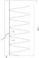
Fig. 1 is a plot of the magnetic flux (mf) versus time (t), as detected by a magnetometer located in the proximity of the teeth of a toothed wheel which controls a gripper, lacking any malfunctions of the gripper driving group; -
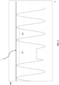
Fig. 2 is a plot like that ofFig. 1 , when there is a broken tooth of the toothed wheel which controls a gripper; -
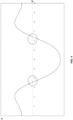
Fig. 3 is a plot like that ofFig. 1 , when malfunctions happen in the gripper driving group; -
Fig. 4 is a plot of the acceleration (a) of the toothed wheels which control the grippers as a function of the degrees (d) of advancement of a work cycle of the weaving loom; and -
Fig. 5 is an overall view illustrating a preferred positioning of said magnetometer in the proximity of a toothed wheel of a preferred gripper driving group. - According to the present invention, to solve the problem highlighted above, the Applicant first identified the toothed wheel, and particularly its toothed crown (hereinafter also simply referred to as "crown"), as the more promising "sentinel" component of the gripper driving group for detecting any malfunctions of the other components of said gripper driving group. The toothed wheel is in fact the last component of the kinematic chain of the gripper driving group and it is rigidly connected to a relative support shaft, so that any possible malfunction of the other components of the gripper driving group, upstream of the toothed wheel, inevitably results in a corresponding anomaly in the toothed wheel movement. Furthermore, by performing the detection at the crown of said toothed wheel, the very presence of the teeth is a convenient element for indexing the detection along the perimeter of the toothed wheel and therefore with respect to the loom work cycle. Finally, the toothed wheel crown, or at least one portion thereof, is easily accessible for placing a sensing device in the sector of the toothed wheel which is not engaged by the flexible strap. As an alternative to using the toothed wheel crown, a dedicated toothed crown can also be used for this purpose, integral with the same support shaft of the toothed wheel, where this option is more effective or convenient in view of the positioning of the toothed wheel or the material it is made of.
- In order to obtain a sufficiently sensitive control device, which is thus capable of promptly signalling malfunctions of the gripper driving group when said malfunctions are still in their initial condition, the movement of the toothed wheel should be detected using detection devices which have a high precision and accuracy, for example detection devices provided with high-grade optical or electronic sensors available on the market, so as to detect any possible anomaly in the toothed wheel movement, such as for example eccentric rotations or phase variations.
- By plotting the changes in the values detected by said detection devices as a function of time, during the toothed crown movement in front of the sensor, an "electronic profile" of the toothed wheel toothing can be obtained, which reproduces - in a qualitative but highly representative way of the actual condition - the physical profile of the toothed crown. An analysis of the electronic profiles detected in subsequent cycles for a same toothed wheel, by analysis algorithms contained in a control software of the diagnostic device of the invention, allows then for a timely and fully automatic identification of the onset of possible anomalies in the movement of said wheel.
- A series of experimental tests using the detection device described above made it possible to verify that each malfunction of a specific component of the gripper driving group actually corresponds to a well-defined configuration of the electronic profile of the toothed wheel crown. It was therefore possible to set up a series of algorithms for analysing said electronic profile, each of them allowing to promptly detect the onset of one of these specific configurations of the electronic profile. When this happens, the diagnostic device control software, which incorporates such analysis algorithms, activates a corresponding warning signal which addresses the operator to check one or more components of the gripper driving group, and/or immediately stops the loom operation when a malfunction related to the detected electronic profile configuration implies a possible imminent failure of a component.
- Maintenance, adjustment or replacement operations can thus be carried out only on those components for which a possible malfunction has been warned, with a notable increase in effectiveness both in terms of reducing the time required to identify the failure which caused the profile anomaly, and because the anomaly is detected at a very early stage and therefore before the failure of that component could cause any failure to the other components or to the fabric being processed, and finally also because a maintenance, adjustment or replacement intervention of the components of the gripper driving group can be postponed, with respect to the times prescribed by the scheduled periodic maintenance, until some specific anomaly is detected in the electronic profile of the toothed wheel crown, thus allowing the useful life of such components to be significantly extended without compromising the operational safety of the gripper driving group.
- Some specific events of malfunction of the components of the gripper driving group will be briefly presented below, showing how such malfunctions are related to typical anomalies in the electronic profile of the crown of the toothed wheels which control the grippers, which typical anomalies can therefore be easily automatically detected through corresponding analysis algorithms which analyse said electronic profile.
- To perform these tests, and in consideration of the fact that the toothed wheels normally manufactured by the Applicant contain ferromagnetic material in their external crown, the Applicant has developed a particular device for magnetic detection of the toothed profile of the toothed wheels which control the grippers, illustrated in
Fig. 5 , based on the use of a magnet and a magnetometer M - such as for example a Hall effect sensor - installed at a known distance in the proximity of the toothed crown C of a toothed wheel D of a gripper driving group G. When the toothed wheel D is rotating, in fact, the magnetometer M detects a variable magnetic field - determined by the constant magnetic field induced by the permanent magnet, as modified by the ferromagnetic material of the moving toothed wheel D - having a higher value at the teeth tips and a lower value at the bottom of the space between two successive teeth, the detected magnetic field being approximately proportional to the distance between the teeth profile and the magnetometer M. This detection device made it possible to carry out a particularly accurate detection of the anomalies in the toothed wheel D movement. - Under this condition, i.e. when the gripper driving group G works perfectly regularly and the toothed wheel D is therefore subject to standard wear, caused by repeated contact with the gripper-bearing straps, the electronic profile appears as schematically indicated in
Fig. 1 , where all the profile peaks are of almost constant height and therefore the envelope line of such peaks is astraight line 1 or a line with slight periodic oscillations connected to a possible general hunting in the loom operating cycle. In both cases the time Δt which elapses between pairs of successive peaks is constant, i.e. Δt1 = Δt2 as illustrated inFig. 1 . Although the time Δt varies along the loom work cycle as a function of the variable acceleration of the toothed wheel D , such changes are in fact slow enough not to lead to a significant variation in the Δt between two pairs of successive peaks. - In this condition of regular operation of the gripper driving group G, it is however possible that the diagnostic device detects in the electronic profile some peaks of significantly lower height than all the others or even a missing peak. This type of anomaly, in a generally regular profile, corresponds to crown teeth which, respectively, have suffered partial breakages or have been completely cut off from the toothed wheel D . This situation can be easily highlighted by comparing the Δt of pairs of successive peaks since, in correspondence with a broken tooth, Δt1 is much greater - approximately double - than Δt2 as illustrated in
Fig. 2 . - In case of excessive wear of the support bearings of the toothed wheel support shaft A, the motion of said support shaft A and of the toothed wheel D keyed thereto is no longer perfectly circular but, due to failure to the bearings, the support shaft A axis oscillates irregularly with respect to the original fixed position, depending on the applied loads. Therefore, in this case the toothed wheel crown electronic profile shows progressive and periodic variations in the height of the peaks, which are not caused by the teeth wear but by the toothed wheel D oscillations resulting from the non-regular movement of its support shaft A.
- Therefore, as illustrated in
Fig. 3 , the envelope line of the electronic profile peaks takes the shape of aline 2 with wide oscillations. It is therefore possible to provide an analysis algorithm, in the control software of the diagnostic device of the invention, capable of detecting the moment when the straight or withslight oscillations line 1 turns into theline 2 with wider periodic oscillations or, more precisely, the moment when the increase of the maximum height of said periodic oscillations, with respect to their minimum or zero initial value, exceeds a set threshold. In this case the control software delivers a warning signal to carry out maintenance/replacement on the support bearings of the toothed wheel support shaft A. - Wear phenomena in the kinematics of the gripper driving group G can lead to an excessive increase of play between the internal components of the gripper driving group G and consequently to the onset of play in the toothed wheel D rotary movement. This play is pointed out by an incremental rotary movement of the toothed wheel D at the motion law areas wherein the toothed wheel D undergoes an acceleration sign change. The plot of
Fig. 4 illustrates the variation of the toothed wheel D angular acceleration over an entire weft insertion cycle; according to a usual textile convention, the acceleration variation is reported in ordinates while the weft insertion cycle is reported in abscissas in the plot with reference to a complete 360° rotation of the main control axis of the weaving loom. As is evident from the plot, the acceleration reverses sign twice in one work cycle of the loom. - To detect this type of malfunction, one of the analysis algorithms of the control software of the diagnostic device of the invention verifies on the toothed wheel D electronic profile whether, in correspondence with a sufficiently wide angular interval around the points of sign change of the acceleration, the time period Δt1 between a first pair of successive peaks and the time period Δt2 between an immediately adjacent pair of successive peaks are equal or different, that is whether the ratio Δt2/Δt1 differs by a set value from 1. If this condition occurs, the diagnostic device control software delivers a warning signal to carry out a maintenance intervention to adjust the plays of the gripper driving group G components or replace worn components. In the case of a gripper driving group G having a kinematic mechanism of the type described in
EP-3298185 , the maintenance intervention involves an adjustment of the play of the sliding-blocks of the sliding-block cursor on the worm screw thread and/or a maintenance/replacement of the rod head bearing. - Finally, there are some possible malfunctions of the gripper driving group G which do not depend on wear phenomena but rather on the failure of mechanical joints between components of the gripper driving group G, such as, for example, the failure of the toothed wheel D keying onto the relevant support shaft A, and which are therefore particularly serious for the consequences they can cause.
- This type of failure causes an instantaneous or progressive phase shift of the toothed wheel D from its original position and therefore can be easily detected using another algorithm of the diagnostic device of the present invention which compares, in successive cycles, the period of time Δt1 between two successive peaks corresponding to the same pair of teeth of the toothed crown C . In theory, in fact, the period of time Δt1 detected at a given position of the loom main control axis remains substantially constant in subsequent cycles; however, when the period of time Δt1 increases over a series of subsequent weft insertion cycles at those areas of the loom work cycle wherein the acceleration of the toothed wheel D is maximum, this means that a structural failure started of a mechanical connection between components of the gripper driving group G and, in consideration of the probable severity of the consequences and the imminence of a total failure, the control software of the diagnostic device of the present invention sends a warning signal to the operator and simultaneously stops the weaving loom operation. In the case of a gripper driving group G having a kinematic mechanism of the type described in
EP-3298185 , for example, said structural failure may concern, in addition to that indicated above of the toothed wheel D keying onto the worm screw shaft, also the failure of the rotatable idle hinge mechanical connection between a sliding-block holder and the sliding-block cursor. - From the previous description, it can be noted how the weaving loom equipped with a gripper driving group G diagnostic device of the present invention has fully achieved the intended objects, first by identifying in the toothed wheel crown the most promising "sentinel" component for providing early indications on malfunctions of the mechanical components of the gripper driving group G. Secondly, by detecting special electronic profiles of the toothed wheels and then carrying out completely innovative analyses on said electronic profiles, by correlating the various possible anomalies of said electronic profiles with malfunctions of specific components of the gripper driving group G through appropriate analysis algorithms and finally warning targeted adjustment/maintenance/replacement interventions and/or the direct stop of the weaving loom operation when the detected malfunction is prone to an imminent failure of a component of the gripper driving group G. Finally, by using a magnetic detection device for detecting the toothed crown C profile, which has the advantage of being completely independent in its operation from the presence of dust and of variable conditions of lighting, temperature, and humidity, does not need any physical contact with the detected mechanical component, and also offers a high degree of accuracy and consistency of the electronic profile obtained with the toothed crown C physical profile.
- It is understood, however, that the invention must not be considered as limited to the specific arrangements illustrated above, which are only exemplary embodiments thereof, but that different variants are possible, all within the reach of a person skilled in the art, without thereby departing from the scope of protection of the invention itself, which is only defined by the following claims.
Claims (16)
- Gripper weaving loom equipped with a diagnostic device for a gripper driving group (G), said gripper driving group (G) including a kinematic mechanism which transforms the rotary movement of a weaving loom main motor into a reciprocating rotary movement of a support shaft (A) of a toothed wheel (D) which, in turn, causes the reciprocating rectilinear movement of a gripper of the loom, said diagnostic device including a detection device (M), arranged in the proximity of a toothed crown (C) integral with said support shaft (A), characterized in that said detection device (M) detects a parameter correlated to the physical profile of said toothed crown (C) in rotation during loom operation, and a control software which performs the following steps:a. builds an electronic profile of said toothed crown (C), plotting the variations of said parameter detected by said detection device (M), said electronic profile including a series of peaks separated by troughs, representative of said toothed crown (C) teeth;b. detects possible anomalies of said electronic profile consisting in changes in said electronic profile compared to a condition corresponding to a regular operation of the gripper driving group (G), wherein said peaks are all the same height;c. finds out, by means of one or more analysis algorithms, a correlation between said detected anomalies of the electronic profile and corresponding malfunctions of at least one specific component of said gripper driving group (G); andd. delivers a corresponding warning signal to carry out a maintenance, adjustment, or replacement intervention on said at least one specific component.
- Gripper weaving loom equipped with a diagnostic device according to claim 1, wherein said anomaly is a shape change of the envelope line of the peaks of said electronic profile of the toothed crown (C), over successive work cycles of the loom, from a straight line (1) or a line with slight periodic oscillations to a line (2) having wider periodic oscillations, and the malfunction corresponding to said anomaly is a failure of the bearings of said support shaft (A) of the toothed wheel (D).
- Gripper weaving loom equipped with a diagnostic device according to claim 2, wherein said control software delivers the above-mentioned warning signal of step d., when the increase of the maximum height of said periodic oscillations, with respect to their initial value, exceeds a predefined threshold.
- Gripper weaving loom equipped with a diagnostic device according to claim 1, wherein said anomaly is a period of time Δt1 between a first pair of successive peaks different from a period of time Δt2 between a second adjacent pair of successive peaks of said electronic profile, in correspondence of those areas of the loom work cycle wherein the toothed wheel (D) acceleration undergoes a sign change, and the malfunction corresponding to said anomaly is an excessive increase of play of the components of the gripper driving group (G).
- Gripper weaving loom equipped with a diagnostic device according to claim 4, wherein said control software delivers the above-mentioned warning signal of step d., when the ratio between said periods of time Δt2/Δt1 differs from 1 by a set value.
- Gripper weaving loom equipped with a diagnostic device according to claim 1, wherein said anomaly is the increase, over successive work cycles of the loom, of the period of time Δt1 between two successive peaks corresponding to the same pair of teeth of the toothed crown (C), in correspondence of those areas of the loom work cycle wherein the toothed wheel (D) acceleration is maximum, and the malfunction corresponding to said anomaly is a failure of mechanical joints between components of the gripper driving group (G).
- Gripper weaving loom equipped with a diagnostic device according to claim 6, wherein said failure of mechanical joints between components of the gripper driving group (G) is a failure of the toothed wheel (D) keying onto said support shaft (A).
- Gripper weaving loom equipped with a diagnostic device according to claim 1, wherein said kinematic mechanism includes a coupling between a sliding-block cursor, which is driven in reciprocating rectilinear movement by the loom main motor by means of a rod/crank mechanism, and a variable-pitch worm screw, free to rotate on support bearings and driven in a reciprocating rotary movement by said sliding-block cursor, wherein pairs of opposite sliding-blocks are housed in a respective sliding-block holder element which is idle-hinged on said cursor and said toothed wheel (D) is keyed to one end of said variable-pitch worm screw.
- Gripper weaving loom equipped with a diagnostic device according to claim 8, wherein said anomaly is a period of time Δt1 between a first pair of successive peaks different from a period of time Δt2 between a second adjacent pair of successive peaks of said electronic profile, in correspondence of those areas of the loom work cycle wherein the toothed wheel (D) acceleration undergoes a sign change, and the malfunction corresponding to said anomaly is an excessive increase of play of pairs of sliding-blocks of the sliding-block cursor on a thread of said variable-pitch worm screw and/or a failure of the support bearing of the rod of said rod/crank mechanism.
- Gripper weaving loom equipped with a diagnostic device according to claim 9, wherein said control software delivers the above-mentioned warning signal of step d), when the ratio between said period of times Δt2/Δt1 differs from 1 by a set value.
- Gripper weaving loom equipped with a diagnostic device according to claim 8, wherein said anomaly is the increase, over successive work cycles of the loom, of the period of time Δt1 between two successive peaks corresponding to the same pair of teeth of the toothed crown (C), in correspondence of those areas of the loom work cycle wherein the toothed wheel (D) acceleration is maximum, and the malfunction corresponding to said anomaly is a failure of an idle hinge connecting a sliding-block holder element to the sliding-block cursor.
- Gripper weaving loom equipped with a diagnostic device according to any one of the preceding claims, wherein said detection device (M) includes an optical sensor, an electronic sensor, or a magnetic sensor.
- Gripper weaving loom equipped with a diagnostic device according to claim 12, wherein said magnetic sensor includes a magnet which forms a magnetic field in the proximity of the toothed crown (C) of said toothed wheel (D), and a magnetometer (M) detecting the magnetic flux induced by said magnet and modified by said toothed crown (C) rotation, as said parameter correlated to the physical profile of the toothed crown (C).
- Gripper weaving loom equipped with a diagnostic device according to claim 13, wherein said magnetometer (M) is a Hall effect sensor.
- Gripper weaving loom equipped with a diagnostic device according to any one of the preceding claims, wherein, in relation to an anomaly in the electronic profile of said toothed crown (C) whose correlated malfunction implies a possible imminent breakage of a component, the control software of the diagnostic device stops the loom operation at the same time in which delivers the above-mentioned warning signal of step d.
- Gripper weaving loom equipped with a diagnostic device according to any one of the preceding claims, wherein said toothed crown (C) is the toothed crown (C) of said toothed wheel (D).
Applications Claiming Priority (1)
| Application Number | Priority Date | Filing Date | Title |
|---|---|---|---|
| IT102023000011403A IT202300011403A1 (en) | 2023-06-06 | 2023-06-06 | Rapier weaving machine equipped with a rapier control group diagnostic device |
Publications (2)
| Publication Number | Publication Date |
|---|---|
| EP4474545A1 true EP4474545A1 (en) | 2024-12-11 |
| EP4474545B1 EP4474545B1 (en) | 2025-12-17 |
Family
ID=87800805
Family Applications (1)
| Application Number | Title | Priority Date | Filing Date |
|---|---|---|---|
| EP24176867.0A Active EP4474545B1 (en) | 2023-06-06 | 2024-05-20 | Gripper weaving loom equipped with a diagnostic device of the gripper driving group |
Country Status (4)
| Country | Link |
|---|---|
| EP (1) | EP4474545B1 (en) |
| JP (1) | JP2024175668A (en) |
| CN (1) | CN119082994A (en) |
| IT (1) | IT202300011403A1 (en) |
Citations (5)
| Publication number | Priority date | Publication date | Assignee | Title |
|---|---|---|---|---|
| JP2000096388A (en) | 1998-09-21 | 2000-04-04 | Tsudakoma Corp | Rapier loom abnormality detection device |
| WO2017081605A1 (en) * | 2015-11-12 | 2017-05-18 | Camozzi Digital S.R.L. | System for monitoring operating parameters of components of a weaving loom |
| EP3298185A1 (en) | 2015-05-22 | 2018-03-28 | ITEMA S.p.A. | Mechanism for controlling the reciprocating movement of weft carrying grippers in a weaving loom |
| WO2020254981A1 (en) * | 2019-06-18 | 2020-12-24 | Itema S.P.A. | Control method of a weft insertion system of a gripper loom |
| EP4008817A1 (en) * | 2020-12-07 | 2022-06-08 | Picanol | Method and device for determining a movement parameter of a gripper |
-
2023
- 2023-06-06 IT IT102023000011403A patent/IT202300011403A1/en unknown
-
2024
- 2024-05-20 EP EP24176867.0A patent/EP4474545B1/en active Active
- 2024-05-31 JP JP2024088576A patent/JP2024175668A/en active Pending
- 2024-06-06 CN CN202410725320.7A patent/CN119082994A/en active Pending
Patent Citations (5)
| Publication number | Priority date | Publication date | Assignee | Title |
|---|---|---|---|---|
| JP2000096388A (en) | 1998-09-21 | 2000-04-04 | Tsudakoma Corp | Rapier loom abnormality detection device |
| EP3298185A1 (en) | 2015-05-22 | 2018-03-28 | ITEMA S.p.A. | Mechanism for controlling the reciprocating movement of weft carrying grippers in a weaving loom |
| WO2017081605A1 (en) * | 2015-11-12 | 2017-05-18 | Camozzi Digital S.R.L. | System for monitoring operating parameters of components of a weaving loom |
| WO2020254981A1 (en) * | 2019-06-18 | 2020-12-24 | Itema S.P.A. | Control method of a weft insertion system of a gripper loom |
| EP4008817A1 (en) * | 2020-12-07 | 2022-06-08 | Picanol | Method and device for determining a movement parameter of a gripper |
Also Published As
| Publication number | Publication date |
|---|---|
| JP2024175668A (en) | 2024-12-18 |
| EP4474545B1 (en) | 2025-12-17 |
| CN119082994A (en) | 2024-12-06 |
| IT202300011403A1 (en) | 2024-12-06 |
Similar Documents
| Publication | Publication Date | Title |
|---|---|---|
| JP4298508B2 (en) | Tensioning device with measuring function | |
| US5431273A (en) | Apparatus and method for detecting a missing ejector in a sorting and conveying system | |
| US5689067A (en) | Diagnostic method and apparatus for monitoring the wear of at least an engine timing chain | |
| JP2002130531A (en) | Abnormality diagnosis and deterioration prediction method and device in valve device | |
| US11906397B2 (en) | Active backlash detection methods and systems | |
| WO2019022852A1 (en) | Blade vibration monitor with self adjusting sensor gap mechanism | |
| EP4474545B1 (en) | Gripper weaving loom equipped with a diagnostic device of the gripper driving group | |
| PL247205B1 (en) | Conveyor for a mining system and methods of controlling the conveyor in a mining system | |
| JP4546649B2 (en) | How to monitor the cycle of inserting a weft thread into a loom | |
| JP2021085694A (en) | Ball screw condition monitoring device and condition monitoring method | |
| JP2008286302A (en) | Abnormality detection mechanism of rotary joint and rotary valve body | |
| EP4471199B1 (en) | Gripper weaving loom including a wear monitoring device of the front portion of gripper control straps | |
| CN109667001B (en) | Method and device for monitoring the belt tension of a drive belt of a ring spinning machine | |
| CN120521856B (en) | A rocker arm assembly detection system and control method thereof | |
| CN106489234B (en) | Methods of Monitoring Collision | |
| EP3821064B1 (en) | Control method of a weft insertion system of a gripper loom | |
| CN1985039A (en) | Method for checking a gripper driving wheel of a mechanical weaving loom, gripper driving wheel, and gripper mechanical weaving loom | |
| CN103671061B (en) | A kind of oblique tray type compressor speed measuring device | |
| JP2000096388A (en) | Rapier loom abnormality detection device | |
| CN217369828U (en) | Monitoring device for easy-open-end composite punch | |
| EP3644147B1 (en) | Belt drive system and method | |
| TWI854386B (en) | Surveillance object data storage device, surveillance object data storage method, surveillance object data storage program | |
| JP2021085693A (en) | Ball screw condition monitoring device and condition monitoring method | |
| KR100614636B1 (en) | How to detect motor abnormalities | |
| FI110337B (en) | Arrangements for temperature control in connection with a piston engine |
Legal Events
| Date | Code | Title | Description |
|---|---|---|---|
| PUAI | Public reference made under article 153(3) epc to a published international application that has entered the european phase |
Free format text: ORIGINAL CODE: 0009012 |
|
| STAA | Information on the status of an ep patent application or granted ep patent |
Free format text: STATUS: THE APPLICATION HAS BEEN PUBLISHED |
|
| AK | Designated contracting states |
Kind code of ref document: A1 Designated state(s): AL AT BE BG CH CY CZ DE DK EE ES FI FR GB GR HR HU IE IS IT LI LT LU LV MC ME MK MT NL NO PL PT RO RS SE SI SK SM TR |
|
| STAA | Information on the status of an ep patent application or granted ep patent |
Free format text: STATUS: REQUEST FOR EXAMINATION WAS MADE |
|
| 17P | Request for examination filed |
Effective date: 20250414 |
|
| GRAP | Despatch of communication of intention to grant a patent |
Free format text: ORIGINAL CODE: EPIDOSNIGR1 |
|
| STAA | Information on the status of an ep patent application or granted ep patent |
Free format text: STATUS: GRANT OF PATENT IS INTENDED |
|
| RIC1 | Information provided on ipc code assigned before grant |
Ipc: D03D 47/27 20060101AFI20250825BHEP Ipc: D03D 51/44 20060101ALI20250825BHEP |
|
| INTG | Intention to grant announced |
Effective date: 20250917 |
|
| GRAS | Grant fee paid |
Free format text: ORIGINAL CODE: EPIDOSNIGR3 |
|
| GRAA | (expected) grant |
Free format text: ORIGINAL CODE: 0009210 |
|
| STAA | Information on the status of an ep patent application or granted ep patent |
Free format text: STATUS: THE PATENT HAS BEEN GRANTED |
|
| AK | Designated contracting states |
Kind code of ref document: B1 Designated state(s): AL AT BE BG CH CY CZ DE DK EE ES FI FR GB GR HR HU IE IS IT LI LT LU LV MC ME MK MT NL NO PL PT RO RS SE SI SK SM TR |
|
| REG | Reference to a national code |
Ref country code: CH Ref legal event code: F10 Free format text: ST27 STATUS EVENT CODE: U-0-0-F10-F00 (AS PROVIDED BY THE NATIONAL OFFICE) Effective date: 20251217 Ref country code: GB Ref legal event code: FG4D |
|
| REG | Reference to a national code |
Ref country code: DE Ref legal event code: R096 Ref document number: 602024001704 Country of ref document: DE |
|
| REG | Reference to a national code |
Ref country code: LT Ref legal event code: MG9D |
|
| PG25 | Lapsed in a contracting state [announced via postgrant information from national office to epo] |
Ref country code: NO Free format text: LAPSE BECAUSE OF FAILURE TO SUBMIT A TRANSLATION OF THE DESCRIPTION OR TO PAY THE FEE WITHIN THE PRESCRIBED TIME-LIMIT Effective date: 20260317 |
|
| PG25 | Lapsed in a contracting state [announced via postgrant information from national office to epo] |
Ref country code: FI Free format text: LAPSE BECAUSE OF FAILURE TO SUBMIT A TRANSLATION OF THE DESCRIPTION OR TO PAY THE FEE WITHIN THE PRESCRIBED TIME-LIMIT Effective date: 20251217 Ref country code: HR Free format text: LAPSE BECAUSE OF FAILURE TO SUBMIT A TRANSLATION OF THE DESCRIPTION OR TO PAY THE FEE WITHIN THE PRESCRIBED TIME-LIMIT Effective date: 20251217 |
|
| PG25 | Lapsed in a contracting state [announced via postgrant information from national office to epo] |
Ref country code: RS Free format text: LAPSE BECAUSE OF FAILURE TO SUBMIT A TRANSLATION OF THE DESCRIPTION OR TO PAY THE FEE WITHIN THE PRESCRIBED TIME-LIMIT Effective date: 20260317 |
|
| REG | Reference to a national code |
Ref country code: NL Ref legal event code: MP Effective date: 20251217 |
|
| PG25 | Lapsed in a contracting state [announced via postgrant information from national office to epo] |
Ref country code: LV Free format text: LAPSE BECAUSE OF FAILURE TO SUBMIT A TRANSLATION OF THE DESCRIPTION OR TO PAY THE FEE WITHIN THE PRESCRIBED TIME-LIMIT Effective date: 20251217 |
|
| PG25 | Lapsed in a contracting state [announced via postgrant information from national office to epo] |
Ref country code: BG Free format text: LAPSE BECAUSE OF FAILURE TO SUBMIT A TRANSLATION OF THE DESCRIPTION OR TO PAY THE FEE WITHIN THE PRESCRIBED TIME-LIMIT Effective date: 20251217 |
|
| REG | Reference to a national code |
Ref country code: AT Ref legal event code: MK05 Ref document number: 1868555 Country of ref document: AT Kind code of ref document: T Effective date: 20251217 |
|
| PG25 | Lapsed in a contracting state [announced via postgrant information from national office to epo] |
Ref country code: NL Free format text: LAPSE BECAUSE OF FAILURE TO SUBMIT A TRANSLATION OF THE DESCRIPTION OR TO PAY THE FEE WITHIN THE PRESCRIBED TIME-LIMIT Effective date: 20251217 |
|
| PG25 | Lapsed in a contracting state [announced via postgrant information from national office to epo] |
Ref country code: LT Free format text: LAPSE BECAUSE OF FAILURE TO SUBMIT A TRANSLATION OF THE DESCRIPTION OR TO PAY THE FEE WITHIN THE PRESCRIBED TIME-LIMIT Effective date: 20251217 |
|
| PG25 | Lapsed in a contracting state [announced via postgrant information from national office to epo] |
Ref country code: SM Free format text: LAPSE BECAUSE OF FAILURE TO SUBMIT A TRANSLATION OF THE DESCRIPTION OR TO PAY THE FEE WITHIN THE PRESCRIBED TIME-LIMIT Effective date: 20251217 |
|
| PG25 | Lapsed in a contracting state [announced via postgrant information from national office to epo] |
Ref country code: ES Free format text: LAPSE BECAUSE OF FAILURE TO SUBMIT A TRANSLATION OF THE DESCRIPTION OR TO PAY THE FEE WITHIN THE PRESCRIBED TIME-LIMIT Effective date: 20251217 |
|
| PG25 | Lapsed in a contracting state [announced via postgrant information from national office to epo] |
Ref country code: PL Free format text: LAPSE BECAUSE OF FAILURE TO SUBMIT A TRANSLATION OF THE DESCRIPTION OR TO PAY THE FEE WITHIN THE PRESCRIBED TIME-LIMIT Effective date: 20251217 |
|
| PGFP | Annual fee paid to national office [announced via postgrant information from national office to epo] |
Ref country code: IT Payment date: 20260601 Year of fee payment: 3 |
|
| PGFP | Annual fee paid to national office [announced via postgrant information from national office to epo] |
Ref country code: DE Payment date: 20260421 Year of fee payment: 3 |
|
| PG25 | Lapsed in a contracting state [announced via postgrant information from national office to epo] |
Ref country code: AT Free format text: LAPSE BECAUSE OF FAILURE TO SUBMIT A TRANSLATION OF THE DESCRIPTION OR TO PAY THE FEE WITHIN THE PRESCRIBED TIME-LIMIT Effective date: 20251217 |
|
| PGFP | Annual fee paid to national office [announced via postgrant information from national office to epo] |
Ref country code: BE Payment date: 20260520 Year of fee payment: 3 |
|
| PG25 | Lapsed in a contracting state [announced via postgrant information from national office to epo] |
Ref country code: EE Free format text: LAPSE BECAUSE OF FAILURE TO SUBMIT A TRANSLATION OF THE DESCRIPTION OR TO PAY THE FEE WITHIN THE PRESCRIBED TIME-LIMIT Effective date: 20251217 |
|
| PG25 | Lapsed in a contracting state [announced via postgrant information from national office to epo] |
Ref country code: PT Free format text: LAPSE BECAUSE OF FAILURE TO SUBMIT A TRANSLATION OF THE DESCRIPTION OR TO PAY THE FEE WITHIN THE PRESCRIBED TIME-LIMIT Effective date: 20260417 Ref country code: IS Free format text: LAPSE BECAUSE OF FAILURE TO SUBMIT A TRANSLATION OF THE DESCRIPTION OR TO PAY THE FEE WITHIN THE PRESCRIBED TIME-LIMIT Effective date: 20260417 |
|
| PG25 | Lapsed in a contracting state [announced via postgrant information from national office to epo] |
Ref country code: CZ Free format text: LAPSE BECAUSE OF FAILURE TO SUBMIT A TRANSLATION OF THE DESCRIPTION OR TO PAY THE FEE WITHIN THE PRESCRIBED TIME-LIMIT Effective date: 20251217 |
|
| PGFP | Annual fee paid to national office [announced via postgrant information from national office to epo] |
Ref country code: TR Payment date: 20260514 Year of fee payment: 3 |
|
| PG25 | Lapsed in a contracting state [announced via postgrant information from national office to epo] |
Ref country code: SK Free format text: LAPSE BECAUSE OF FAILURE TO SUBMIT A TRANSLATION OF THE DESCRIPTION OR TO PAY THE FEE WITHIN THE PRESCRIBED TIME-LIMIT Effective date: 20251217 |
|
| PG25 | Lapsed in a contracting state [announced via postgrant information from national office to epo] |
Ref country code: SE Free format text: LAPSE BECAUSE OF FAILURE TO SUBMIT A TRANSLATION OF THE DESCRIPTION OR TO PAY THE FEE WITHIN THE PRESCRIBED TIME-LIMIT Effective date: 20251217 |