EP4474321A1 - Media conveying apparatus and image forming apparatus - Google Patents
Media conveying apparatus and image forming apparatus Download PDFInfo
- Publication number
- EP4474321A1 EP4474321A1 EP24179628.3A EP24179628A EP4474321A1 EP 4474321 A1 EP4474321 A1 EP 4474321A1 EP 24179628 A EP24179628 A EP 24179628A EP 4474321 A1 EP4474321 A1 EP 4474321A1
- Authority
- EP
- European Patent Office
- Prior art keywords
- pair
- conveyance
- conveyor
- unit
- image forming
- Prior art date
- Legal status (The legal status is an assumption and is not a legal conclusion. Google has not performed a legal analysis and makes no representation as to the accuracy of the status listed.)
- Granted
Links
Images








Classifications
-
- B—PERFORMING OPERATIONS; TRANSPORTING
- B65—CONVEYING; PACKING; STORING; HANDLING THIN OR FILAMENTARY MATERIAL
- B65H—HANDLING THIN OR FILAMENTARY MATERIAL, e.g. SHEETS, WEBS, CABLES
- B65H5/00—Feeding articles separated from piles; Feeding articles to machines
- B65H5/36—Article guides or smoothers, e.g. movable in operation
-
- B—PERFORMING OPERATIONS; TRANSPORTING
- B41—PRINTING; LINING MACHINES; TYPEWRITERS; STAMPS
- B41J—TYPEWRITERS; SELECTIVE PRINTING MECHANISMS, i.e. MECHANISMS PRINTING OTHERWISE THAN FROM A FORME; CORRECTION OF TYPOGRAPHICAL ERRORS
- B41J13/00—Devices or arrangements of selective printing mechanisms, e.g. ink-jet printers or thermal printers, specially adapted for supporting or handling copy material in short lengths, e.g. sheets
- B41J13/08—Conveyor bands or like feeding devices
-
- B—PERFORMING OPERATIONS; TRANSPORTING
- B41—PRINTING; LINING MACHINES; TYPEWRITERS; STAMPS
- B41J—TYPEWRITERS; SELECTIVE PRINTING MECHANISMS, i.e. MECHANISMS PRINTING OTHERWISE THAN FROM A FORME; CORRECTION OF TYPOGRAPHICAL ERRORS
- B41J3/00—Typewriters or selective printing or marking mechanisms characterised by the purpose for which they are constructed
- B41J3/44—Typewriters or selective printing mechanisms having dual functions or combined with, or coupled to, apparatus performing other functions
-
- B—PERFORMING OPERATIONS; TRANSPORTING
- B65—CONVEYING; PACKING; STORING; HANDLING THIN OR FILAMENTARY MATERIAL
- B65H—HANDLING THIN OR FILAMENTARY MATERIAL, e.g. SHEETS, WEBS, CABLES
- B65H29/00—Delivering or advancing articles from machines; Advancing articles to or into piles
- B65H29/12—Delivering or advancing articles from machines; Advancing articles to or into piles by means of the nip between two, or between two sets of, moving tapes or bands or rollers
- B65H29/125—Delivering or advancing articles from machines; Advancing articles to or into piles by means of the nip between two, or between two sets of, moving tapes or bands or rollers between two sets of rollers
-
- B—PERFORMING OPERATIONS; TRANSPORTING
- B65—CONVEYING; PACKING; STORING; HANDLING THIN OR FILAMENTARY MATERIAL
- B65H—HANDLING THIN OR FILAMENTARY MATERIAL, e.g. SHEETS, WEBS, CABLES
- B65H29/00—Delivering or advancing articles from machines; Advancing articles to or into piles
- B65H29/12—Delivering or advancing articles from machines; Advancing articles to or into piles by means of the nip between two, or between two sets of, moving tapes or bands or rollers
- B65H29/14—Delivering or advancing articles from machines; Advancing articles to or into piles by means of the nip between two, or between two sets of, moving tapes or bands or rollers and introducing into a pile
-
- B—PERFORMING OPERATIONS; TRANSPORTING
- B65—CONVEYING; PACKING; STORING; HANDLING THIN OR FILAMENTARY MATERIAL
- B65H—HANDLING THIN OR FILAMENTARY MATERIAL, e.g. SHEETS, WEBS, CABLES
- B65H29/00—Delivering or advancing articles from machines; Advancing articles to or into piles
- B65H29/52—Stationary guides or smoothers
-
- B—PERFORMING OPERATIONS; TRANSPORTING
- B65—CONVEYING; PACKING; STORING; HANDLING THIN OR FILAMENTARY MATERIAL
- B65H—HANDLING THIN OR FILAMENTARY MATERIAL, e.g. SHEETS, WEBS, CABLES
- B65H31/00—Pile receivers
- B65H31/04—Pile receivers with movable end support arranged to recede as pile accumulates
- B65H31/08—Pile receivers with movable end support arranged to recede as pile accumulates the articles being piled one above another
- B65H31/10—Pile receivers with movable end support arranged to recede as pile accumulates the articles being piled one above another and applied at the top of the pile
-
- B—PERFORMING OPERATIONS; TRANSPORTING
- B65—CONVEYING; PACKING; STORING; HANDLING THIN OR FILAMENTARY MATERIAL
- B65H—HANDLING THIN OR FILAMENTARY MATERIAL, e.g. SHEETS, WEBS, CABLES
- B65H43/00—Use of control, checking, or safety devices, e.g. automatic devices comprising an element for sensing a variable
- B65H43/04—Use of control, checking, or safety devices, e.g. automatic devices comprising an element for sensing a variable detecting, or responding to, presence of faulty articles
-
- G—PHYSICS
- G03—PHOTOGRAPHY; CINEMATOGRAPHY; ANALOGOUS TECHNIQUES USING WAVES OTHER THAN OPTICAL WAVES; ELECTROGRAPHY; HOLOGRAPHY
- G03G—ELECTROGRAPHY; ELECTROPHOTOGRAPHY; MAGNETOGRAPHY
- G03G15/00—Apparatus for electrographic processes using a charge pattern
- G03G15/65—Apparatus which relate to the handling of copy material
- G03G15/6529—Transporting
-
- G—PHYSICS
- G03—PHOTOGRAPHY; CINEMATOGRAPHY; ANALOGOUS TECHNIQUES USING WAVES OTHER THAN OPTICAL WAVES; ELECTROGRAPHY; HOLOGRAPHY
- G03G—ELECTROGRAPHY; ELECTROPHOTOGRAPHY; MAGNETOGRAPHY
- G03G15/00—Apparatus for electrographic processes using a charge pattern
- G03G15/65—Apparatus which relate to the handling of copy material
- G03G15/6552—Means for discharging uncollated sheet copy material, e.g. discharging rollers, exit trays
-
- B—PERFORMING OPERATIONS; TRANSPORTING
- B65—CONVEYING; PACKING; STORING; HANDLING THIN OR FILAMENTARY MATERIAL
- B65H—HANDLING THIN OR FILAMENTARY MATERIAL, e.g. SHEETS, WEBS, CABLES
- B65H2402/00—Constructional details of the handling apparatus
- B65H2402/10—Modular constructions, e.g. using preformed elements or profiles
-
- B—PERFORMING OPERATIONS; TRANSPORTING
- B65—CONVEYING; PACKING; STORING; HANDLING THIN OR FILAMENTARY MATERIAL
- B65H—HANDLING THIN OR FILAMENTARY MATERIAL, e.g. SHEETS, WEBS, CABLES
- B65H2404/00—Parts for transporting or guiding the handled material
- B65H2404/10—Rollers
- B65H2404/14—Roller pairs
- B65H2404/144—Roller pairs with relative movement of the rollers to / from each other
- B65H2404/1441—Roller pairs with relative movement of the rollers to / from each other involving controlled actuator
-
- B—PERFORMING OPERATIONS; TRANSPORTING
- B65—CONVEYING; PACKING; STORING; HANDLING THIN OR FILAMENTARY MATERIAL
- B65H—HANDLING THIN OR FILAMENTARY MATERIAL, e.g. SHEETS, WEBS, CABLES
- B65H2404/00—Parts for transporting or guiding the handled material
- B65H2404/60—Other elements in face contact with handled material
- B65H2404/61—Longitudinally-extending strips, tubes, plates, or wires
- B65H2404/611—Longitudinally-extending strips, tubes, plates, or wires arranged to form a channel
-
- B—PERFORMING OPERATIONS; TRANSPORTING
- B65—CONVEYING; PACKING; STORING; HANDLING THIN OR FILAMENTARY MATERIAL
- B65H—HANDLING THIN OR FILAMENTARY MATERIAL, e.g. SHEETS, WEBS, CABLES
- B65H2404/00—Parts for transporting or guiding the handled material
- B65H2404/60—Other elements in face contact with handled material
- B65H2404/69—Other means designated for special purpose
- B65H2404/691—Guiding means extensible in material transport direction
-
- B—PERFORMING OPERATIONS; TRANSPORTING
- B65—CONVEYING; PACKING; STORING; HANDLING THIN OR FILAMENTARY MATERIAL
- B65H—HANDLING THIN OR FILAMENTARY MATERIAL, e.g. SHEETS, WEBS, CABLES
- B65H2511/00—Dimensions; Position; Numbers; Identification; Occurrences
- B65H2511/50—Occurence
- B65H2511/52—Defective operating conditions
- B65H2511/528—Jam
-
- B—PERFORMING OPERATIONS; TRANSPORTING
- B65—CONVEYING; PACKING; STORING; HANDLING THIN OR FILAMENTARY MATERIAL
- B65H—HANDLING THIN OR FILAMENTARY MATERIAL, e.g. SHEETS, WEBS, CABLES
- B65H2513/00—Dynamic entities; Timing aspects
- B65H2513/50—Timing
- B65H2513/52—Age; Duration; Life time or chronology of event
-
- B—PERFORMING OPERATIONS; TRANSPORTING
- B65—CONVEYING; PACKING; STORING; HANDLING THIN OR FILAMENTARY MATERIAL
- B65H—HANDLING THIN OR FILAMENTARY MATERIAL, e.g. SHEETS, WEBS, CABLES
- B65H2801/00—Application field
- B65H2801/03—Image reproduction devices
- B65H2801/06—Office-type machines, e.g. photocopiers
-
- B—PERFORMING OPERATIONS; TRANSPORTING
- B65—CONVEYING; PACKING; STORING; HANDLING THIN OR FILAMENTARY MATERIAL
- B65H—HANDLING THIN OR FILAMENTARY MATERIAL, e.g. SHEETS, WEBS, CABLES
- B65H2801/00—Application field
- B65H2801/24—Post -processing devices
- B65H2801/27—Devices located downstream of office-type machines
Definitions
- the present disclosure relates to a media conveying apparatus and an image forming apparatus.
- An image forming apparatus includes an image former, a post-processing device, and a tray.
- the image former forms an image on a sheet.
- the post-processing device performs post processing on the sheet on which an image has been formed.
- the sheet subjected to the post processing is to be stacked on the tray.
- some of such image forming apparatuses are equipped with a tray that is lifted or lowered to allow a large number of sheets to be stacked on the tray.
- Japanese Unexamined Patent Application Publication No. 2021-123490 discloses a configuration in which a post-processing device and a liftable tray are unitized and the unit is installed in an in-body space of the image forming apparatus for the purpose of placing a large number of sheets in a space-saving manner.
- Japanese Unexamined Patent Application Publication No. 2021-123490 requires replacement of the entire unit when the post-processing device is to be replaced with another post-processing device that performs a different post processing process (for example, a binding process, a hole punching process, or a folding process) or when an optional device is to be installed in the in-body space.
- a different post processing process for example, a binding process, a hole punching process, or a folding process
- the present disclosure has been made so as to solve such a problem, and an object of the present disclosure is to provide a media conveying apparatus that includes a tray on which a large number of media can be put and has a high degree of freedom in terms of installation space.
- the present disclosure provides a media conveying apparatus that includes a pair of first defining members, a pair of second defining members, a first conveyor, a second conveyor, and a tray.
- the pair of first defining members defines an upstream part of a conveyance path in a conveyance direction.
- the pair of second defining members defines a downstream part of the conveyance path in the conveyance direction.
- the first conveyor conveys a medium in the upstream part in the conveyance direction.
- the second conveyor conveys the medium in the downstream part in the conveyance direction.
- the tray is disposed downstream from the pair of second defining members in the conveyance direction.
- the tray stacks the medium ejected from the conveyance path.
- the pair of first defining members and the pair of second defining members are movable relative to each other in the conveyance direction to lengthen and shorten the conveyance path including the upstream part and the downstream part.
- the present disclosure also provides an image forming apparatus that includes an image forming device, a housing, and the media conveying apparatus.
- the image forming device forms an image on a medium.
- the housing houses the image forming device and has an in-body space.
- the media conveying apparatus is detachably installed in the in-body space.
- the tray moves up and down along an outer wall of the housing.
- a media conveying apparatus that includes a tray on which a large number of media can be put and has a high degree of freedom in terms of installation space.
- FIGS. 1A to 1C are external views of the image forming apparatus 10 according to an embodiment of the present disclosure.
- the image forming apparatus 10 is an apparatus that forms an image on a sheet S which is an example of a sheet medium (typically, a sheet of paper).
- the image forming apparatus 10 includes a housing 11 and an image forming device 12.
- the housing 11 has a box shape to form an internal space for accommodating components of the image forming apparatus 10.
- the housing 11 has an in-body space 13 that is accessible from the outside of the image forming apparatus 10.
- the in-body space 13 is located, for example, slightly above the center of the housing 11 in the vertical direction.
- An outer wall of the housing 11 has been cut out to expose the in-body space 13 to the outside.
- the in-body space 13 can accommodate a binding unit 30 (post-processing device), a first conveyance unit 50 and a second conveyance unit 60 (media conveying apparatus), and a hole punching unit 70 and a folding unit 80 (optional devices).
- FIG. 1A illustrates a state in which only the binding unit 30 has been disposed in the in-body space 13.
- FIG. 1B illustrates a state in which the first conveyance unit 50 and the second conveyance unit 60 have been disposed in the in-body space 13, together with the binding unit 30.
- FIG. 1C illustrates a state in which both the hole punching unit 70 and the folding unit 80 have been disposed in the in-body space 13, together with the binding unit 30, the first conveyance unit 50, and the second conveyance unit 60.
- one of the hole punching unit 70 and the folding unit 80 may be disposed in the in-body space 13, together with the binding unit 30, the first conveyance unit 50, and the second conveyance unit 60.
- the image forming device 12 forms an image on the sheet S stored in a tray, and ejects the sheet S on which the image has been formed to the binding unit 30, the hole punching unit 70, or the folding unit 80.
- the image forming device 12 may be an inkjet image forming device that forms an image with ink, or may be an electrophotographic image forming device that forms an image with toner. Since the image forming device 12 has a known configuration, a detailed description of the configuration of the image forming device 12 is omitted.
- the hole punching unit 70 and the folding unit 80 are installed in the in-body space 13 of the image forming apparatus 10 such that the hole punching unit 70 and the folding unit 80 are located downstream from the image forming device 12 and upstream from the binding unit 30 on a conveyance path (a path indicated by a dashed arrow in each of FIGS. 1A to 1C ) of the sheet S from the image forming device 12 to the binding unit 30. That is, the sheet S on which an image has been formed by the image forming device 12 is subjected to one or both of a hole punching process (described below) by the hole punching unit 70 and a folding process (described below) by the folding unit 80, and is then delivered to the binding unit 30 and subjected to a binding process to be described below.
- a hole punching process described below
- a folding process described below
- the hole punching unit 70 and the folding unit 80 are detachably installed in the image forming apparatus 10.
- the hole punching unit 70 and the folding unit 80 are removed, the sheet S on which an image has been formed by the image forming device 12 is directly delivered to the binding unit 30 and subjected to the binding process.
- another optional device such as a liquid applying unit is detachably installed at a location in the in-body space 13 where the hole punching unit 70 and the folding unit 80 were disposed before being removed.
- the sheet S on which the image has been formed by the image forming device 12 is first delivered to the liquid applying unit and subjected to a liquid applying process, and is then delivered to the binding unit 30 and subjected to the binding process.
- the liquid applying process refers to a process of applying liquid to a binding position on the surface of the sheet S at which the sheet S is to be bound by the binding unit 30.
- any optional device other than the liquid applying unit may be installed at the location in the in-body space 13 where the hole punching unit 70 and the folding unit 80 were disposed before being removed, so as to perform a desired process on the sheet S.
- Optional devices may be omitted.
- each of the binding unit 30, the first conveyance unit 50, the second conveyance unit 60, the hole punching unit 70, the folding unit 80, and the liquid applying unit is unitized, to which an input-output interface of the sheet S can be connected. That is, in the image forming apparatus 10, the binding unit 30, the hole punching unit 70, the folding unit 80, and the liquid applying unit are replaceable according to the intended use of the image forming apparatus 10.
- input interfaces of the binding unit 30, the hole punching unit 70, the folding unit 80, and the liquid applying unit can be connected to an output interface of the image forming device 12.
- the input interface of the binding unit 30 can also be connected to the hole punching unit 70, the folding unit 80, and the liquid applying unit.
- An output interface of the binding unit 30 can be connected to an input interface of the first conveyance unit 50.
- an input interface of the second conveyance unit 60 can be connected to an output interface of the first conveyance unit 50.
- Adjacent units are detachably connected to each other by a mechanical lock, a magnet, or the like.
- the units installed in the in-body space 13 are each connected to a controller 100 (see FIG. 13 ) by a harness for transmitting and receiving various signals.
- FIG. 2A is a side view of the binding unit 30, which illustrates an internal configuration thereof.
- FIG. 2B is a plan view of the binding unit 30, which illustrates the internal configuration thereof.
- FIG. 3A is a plan view of the binding unit 30, which illustrates a position of a binder 42.
- FIG. 3B is a side view of the binding unit 30, which illustrates a slit 31a.
- the binding unit 30 performs the binding process (post processing) of binding a plurality of sheets S (sheet bundle Sb) on which images have been formed by the image forming device 12.
- sheet bundle Sb sheet bundle Sb
- a specific example of the post-processing device is not limited to the binding unit 30. As illustrated in FIGS.
- the binding unit 30 includes a binding case 31, an output tray 32, a plurality of conveyance roller pairs 33, 34, 35, and 36, an internal tray 37, a tapping roller 38, return rollers 39, end fences 40L and 40R, side fences 41L and 41R, and the binder 42.
- the binding case 31 has a box shape to form an internal space for accommodating the components (33 to 42) of the binding unit 30.
- a conveyance path Ph1 is formed in the internal space of the binding case 31.
- the conveyance path Ph1 is a space through which the sheet S passes.
- the output tray 32 is supported on an outer surface of the binding case 31.
- the sheet S or the sheet bundle Sb conveyed by the conveyance roller pairs 33 to 36 is stacked on the output tray 32.
- the conveyance roller pairs 33 to 36 are arranged on the conveyance path Ph1 at predetermined intervals.
- the conveyance roller pairs 33 to 36 convey the sheet S along the conveyance path Ph1.
- the conveyance roller pair 33 includes a driving roller 33a and a driven roller 33b disposed in such a way as to face each other across the conveyance path Ph1.
- the driving roller 33a and the driven roller 33b are rotatably supported by the binding case 31.
- the rotary drive force of a conveyance motor is transmitted to the driving roller 33a to rotate the driving roller 33a forward in a direction of conveying the sheet S (clockwise direction in FIGS. 2A and 2B ).
- the driven roller 33b is disposed in such a way as to face the driving roller 33a across the conveyance path Ph1, and is driven by rotation of the driving roller 33a. Driving the conveyance motor causes the sheet S nipped by the driving roller 33a and the driven roller 33b to be conveyed along the conveyance path Ph1.
- the conveyance roller pairs 34 to 36 each have a basic configuration in common with the conveyance roller pair 33.
- the conveyance roller pair 36 includes a driving roller 36a and a driven roller 36b that can be brought into contact with and separated from the driving roller 36a.
- the conveyance roller pair 35 may be slidable in the width direction so as to implement a sorting process in which the sheets S are shifted in the width direction and ejected to the output tray 32.
- the internal tray 37 temporarily supports the plurality of sheets S conveyed by the conveyance roller pair 36.
- the tapping roller 38 is supported at an end of a rotation arm above the internal tray 37. As the rotation arm is rotated, the tapping roller 38 supplies the sheet S nipped by the conveyance roller pair 36 to the internal tray 37.
- the return rollers 39 rotate in contact with the upper surface of the sheet S supported by the internal tray 37 to guide the sheet S toward the conveyance roller pair 36.
- a direction from the conveyance roller pair 36 toward the end fences 40L and 40R is referred to as a "first conveyance direction”
- a direction orthogonal to the first conveyance direction and the thickness direction of the sheet S supported by the internal tray 37 is referred to as a "main scanning direction”.
- the end fences 40L and 40R are in contact with downstream ends of the sheets S supported by the internal tray 37 in the first conveyance direction, and align positions of the sheets S in the first conveyance direction.
- the side fences 41L and 41R are in contact with both width-direction ends of the sheets S supported by the internal tray 37 to align positions of the sheets S in the main scanning direction.
- the binder 42 is disposed at a downstream end of the sheet bundle Sb supported by the internal tray 37 in the first conveyance direction.
- the binder 42 is movable along the sheet bundle Sb supported by the internal tray 37 in the main scanning direction orthogonal to the first conveyance direction.
- the binder 42 is a press-bonding binder that presses and deforms the sheet bundle Sb to bind the sheet bundle Sb.
- the binder 42 is a needle binder that causes a binding needle to penetrate the sheet bundle Sb and binds the sheet bundle Sb.
- the binding unit 30 may include both the press-bonding binder and the needle binder.
- the slit 31a for manual binding is provided at a position facing the binder 42 of the binding case 31.
- a corner of the sheet bundle Sb inserted into the binding case 31 through the slit 31a can be manually bound by the binder 42.
- the binding case 31 further includes guide walls 31b and 31c in such a way as to surround the slit 31a.
- the guide wall 31b performs the positioning of the sheet bundle Sb to be manually bound (that is, the sheet bundle Sb having a corner to be inserted into the slit 31a) in the first conveyance direction.
- the guide wall 31c performs the positioning of the sheet bundle Sb to be manually bound (that is, the sheet bundle Sb having a corner to be inserted into the slit 31a) in the main scanning direction.
- FIG. 4A is a diagram illustrating the binding unit 30 in which the sheet S has not yet reached the conveyance roller pair 36
- FIG. 4B is a diagram illustrating the binding unit 30 in which the sheet S has reached the conveyance roller pair 36.
- FIGS. 5A and 5B are diagrams each illustrating a state of the binding unit 30 performing the binding process.
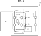
- FIG. 6 is a diagram illustrating the binding unit 30 in the state illustrated in FIG. 5B as viewed from the thickness direction of the sheet S.
- FIGS. 7A and 7B are diagrams illustrating the binding unit 30 in a state where the sheet bundle Sb subjected to the binding process is ejected to the output tray 32.
- the binding unit 30 rotates the conveyance roller pairs 33 to 35 in the forward direction to convey the sheet S supplied from the image forming device 12 along the conveyance path Ph1.
- the driving roller 36a and the driven roller 36b of the conveyance roller pair 36 are separated from each other.
- the binding unit 30 brings the tapping rollers 38 into contact with the sheet S having passed through the conveyance roller pair 35, and rotates the tapping rollers 38 to store the sheet S in the internal tray 37.
- the side fences 41L and 41R are moved in the width direction as illustrated in FIG. 6 to align, in the width direction, positions of the sheets S stored in the internal tray 37.
- the binding unit 30 forms the sheet bundle Sb on the internal tray 37 by repeating the process illustrated in FIGS. 4A to 6 .
- the binding unit 30 causes the binder 42 to face a binding position of the sheet bundle Sb in response to a predetermined number of sheets S being stacked on the internal tray 37.
- the binding unit 30 drives the binder 42 to bind the sheet bundle Sb supported by the internal tray 37.
- the binding unit 30 brings the return rollers 39 into contact with the press-bonded sheet bundle Sb, and rotates the return rollers 39 to cause the sheet bundle Sb to be nipped by the driving roller 36a and the driven roller 36b. Then, as illustrated in FIG. 7B , the binding unit 30 rotates the conveyance roller pair 36 in the forward direction to eject the sheet bundle Sb to the output tray 32.
- FIG. 8A is a side view of the media conveying apparatus in a state where the distance between a first conveyor 55 and a second conveyor 65 has been increased.
- FIG. 8B is a plan view of a main part of the media conveying apparatus in the same state.
- FIG. 9A is a side view of the media conveying apparatus in a state where the distance between the first conveyor 55 and the second conveyor 65 has been reduced.
- FIG. 9B is a plan view of the main part of the media conveying apparatus in the same state.
- the media conveying apparatus includes the first conveyance unit 50 and the second conveyance unit 60. Therefore, in the present specification, the media conveying apparatus is referred to as a "media conveying apparatus (50, 60)".
- the first conveyance unit 50 is disposed upstream from the second conveyance unit 60 in the second conveyance direction.
- a direction from the first conveyance unit 50 toward the second conveyance unit 60 along a conveyance path Ph2 formed inside the media conveying apparatus (50, 60) is referred to as a "second conveyance direction”.
- the media conveying apparatus (50, 60) can be detachably installed in the in-body space.
- the input interface of the media conveying apparatus (50, 60) can be connected to the output interface of the binding unit 30. More specifically, the media conveying apparatus (50, 60) is connected to the output interface of the binding unit 30 from which the output tray 32 has been removed.
- the media conveying apparatus (50, 60) has a function of putting a large number of sheets S or sheet bundles Sb ejected from the binding unit 30 on an output tray 67.
- the first conveyance unit 50 mainly includes a first housing 51, a pair of first defining members 52a and 52b, a pair of first guides 53a and 53b, a sheet sensor 54, and the first conveyor 55.
- the first housing 51 has a box shape to form an internal space for accommodating the components (52 to 55) of the first conveyance unit 50.
- the pair of first defining members 52a and 52b is disposed at a predetermined distance in the vertical direction inside the first housing 51.
- An upstream part of the conveyance path Ph2 in the second conveyance direction is formed between the pair of first defining members 52a and 52b. That is, the pair of first defining members 52a and 52b defines the upstream part of the conveyance path Ph2 in the second conveyance direction.
- the pair of first guides 53a and 53b is disposed at an upstream end of the pair of first defining members 52a and 52b in the second conveyance direction.
- the pair of first guides 53a and 53b is disposed such that the distance between the first guides 53a and 53b increases toward the upstream side in the second conveyance direction.
- the pair of first guides 53a and 53b plays a role of guiding the sheet S or the sheet bundle Sb ejected from the binding unit 30 to a space between the pair of first defining members 52a and 52b.
- the sheet sensor 54 is installed at an upstream end of the conveyance path Ph2 defined by the pair of first defining members 52a and 52b in the second conveyance direction (typically, at the position of the pair of first guides 53a and 53b).
- the sheet sensor 54 outputs a detection signal to the controller 100 when the sheet S is located at an installation position (that is, located between the pair of first guides 53a and 53b), and stops outputting the detection signal when the sheet S is not located at the installation position.
- a reflective or transmissive optical sensor may be employed as the sheet sensor 54.
- FIGS. 10A and 10B are schematic diagrams illustrating a configuration of the first conveyor 55.
- the first conveyor 55 is disposed downstream from the sheet sensor 54 in the second conveyance direction.
- the first conveyor 55 conveys the sheet S or the sheet bundle Sb in the second conveyance direction in the conveyance path Ph2 defined by the pair of first defining members 52a and 52b.
- the first conveyor 55 includes, for example, a driving roller 55a, a driven roller 55b, a drive motor 55c, a driving force transmission mechanism 55d, an arm 55e, and a pressing mechanism 55f.
- the driving roller 55a is disposed on one side of the conveyance path Ph2 in the thickness direction (on the same side as the first defining member 52a in the present embodiment).
- the driven roller 55b is disposed on the other side of the conveyance path Ph2 in the thickness direction (on the same side as the first defining member 52b in the present embodiment). That is, the driving roller 55a and the driven roller 55b are disposed in such a way as to face each other across the conveyance path Ph2.
- the driving roller 55a and the driven roller 55b nip the sheet S or the sheet bundle Sb in the conveyance path Ph2 defined by the pair of first defining members 52a and 52b, and rotate.
- the drive motor 55c generates driving force for rotating the driving roller 55a.
- the driving force of the drive motor 55c is transmitted to the driving roller 55a via the driving force transmission mechanism 55d.
- the driving force transmission mechanism 55d includes a gear, a pulley, a timing belt, or a combination thereof.
- the driving roller 55a rotates in a direction (counterclockwise direction in FIGS. 10A and 10B ) in which the sheet S or the sheet bundle Sb in the conveyance path Ph2 is conveyed in the second conveyance direction.
- the driven roller 55b is driven by rotation of the driving roller 55a.
- the driving roller 55a and the driven roller 55b nip the sheet S or the sheet bundle Sb in the conveyance path Ph2, and rotate to convey the sheet S or the sheet bundle Sb in the second conveyance direction.
- the arm 55e rotatably supports the driven roller 55b.
- the arm 55e rotates in a direction in which the driven roller 55b comes into contact with the driving roller 55a and in a direction in which the driven roller 55b separates from the driving roller 55a.
- the pressing mechanism 55f presses the driven roller 55b against the driving roller 55a.
- the magnitude of pressing force to be generated by the pressing mechanism 55f is set such that the driven roller 55b can be brought into contact with and separated from the driving roller 55a according to the thickness of the sheet S or the sheet bundle Sb entering a space between the driving roller 55a and the driven roller 55b, and that the driving roller 55a and the driven roller 55b can nip and convey the sheet S or the sheet bundle Sb.
- the distance between the driving roller 55a and the driven roller 55b is adjusted according to the thickness of the sheet S or the sheet bundle Sb in the conveyance path Ph2. That is, the first conveyor 55 can convey the sheets S or the sheet bundles Sb having different thicknesses.
- the second conveyance unit 60 mainly includes a second housing 61, a pair of second defining members 62a and 62b, a pair of second guides 63a and 63b, a sheet sensor 64, the second conveyor 65, a second conveyor 66, the output tray 67, and a lift 68.
- the second housing 61 has a box shape to form an internal space for accommodating the components (62 to 66, 68) of the second conveyance unit 60.
- the second housing 61 supports the output tray 67 with an outer wall in such a way as to allow the output tray 67 to be raised and lowered.
- the pair of second defining members 62a and 62b is disposed at a predetermined distance in the vertical direction inside the second housing 61.
- a downstream part of the conveyance path Ph2 in the second conveyance direction is formed between the pair of second defining members 62a and 62b. That is, the pair of second defining members 62a and 62b defines the downstream part of the conveyance path Ph2 in the second conveyance direction.
- the distance between the pair of second defining members 62a and 62b is larger than the distance between the pair of first defining members 52a and 52b.
- the pair of first defining members 52a and 52b and the pair of second defining members 62a and 62b do not need to fully cover the entire conveyance path Ph2, but just need to partially cover the conveyance path Ph2 to such an extent that the sheet S or the sheet bundle Sb conveyed in the second conveyance direction can be supported.
- the pair of second guides 63a and 63b is disposed at an upstream end of the pair of second defining members 62a and 62b in the second conveyance direction.
- the pair of second guides 63a and 63b is disposed such that the distance between the second guides 63a and 63b increases toward the upstream side in the second conveyance direction.
- the pair of second guides 63a and 63b plays a role of guiding the sheet S or the sheet bundle Sb ejected from the first conveyance unit 50 to a space between the pair of second defining members 62a and 62b.
- the sheet sensor 64 is installed at an upstream end of the conveyance path Ph2 defined by the pair of second defining members 62a and 62b in the second conveyance direction (typically, at the position of the pair of second guides 63a and 63b).
- the sheet sensor 64 outputs a detection signal to the controller 100 when the sheet S is located at an installation position (that is, located between the pair of second guides 63a and 63b), and stops outputting the detection signal when the sheet S is not located at the installation position.
- a reflective or transmissive optical sensor may be employed as the sheet sensor 64.
- the second conveyors 65 and 66 are disposed downstream from the sheet sensor 64 in the second conveyance direction.
- the second conveyors 65 and 66 are disposed away from each other in the second conveyance direction.
- the second conveyors 65 and 66 are driven (rotated) in conjunction with each other by a common drive motor 65c.
- the second conveyors 65 and 66 convey the sheet S or the sheet bundle Sb in the second conveyance direction in the conveyance path Ph2 defined by the pair of second defining members 62a and 62b.
- the configurations of the second conveyors 65 and 66 may be similar to the configuration of the first conveyor 55 illustrated in FIGS. 10A and 10B , for example.
- the output tray 67 is supported on an outer surface of the second housing 61 on the downstream side of the pair of second defining members 62a and 62b in the second conveyance direction. Furthermore, the output tray 67 is disposed below a downstream end (outlet) of the conveyance path Ph2 in the second conveyance direction. The output tray 67 can be raised and lowered along the outer surface of the second housing 61. The sheet S or the sheet bundle Sb ejected from the conveyance path Ph2 by the second conveyors 65 and 66 is stacked on the output tray 67.
- the lift 68 raises and lowers the output tray 67.
- the lift 68 includes, for example, pulleys 68a and 68b, a timing belt 68c that is an endless annular belt, and a lifting motor 68d.
- the pulleys 68a and 68b are located away from each other in the vertical direction, and are each rotatably supported by the second housing 61.
- the timing belt 68c is stretched around the pulleys 68a and 68b.
- the lifting motor 68d generates driving force for rotating the pulley 68a (raising and lowering the output tray 67). As a result, the output tray 67 moves up and down which is coupled to the timing belt 68c circulating around the pulleys 68a and 68b.
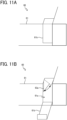
- FIGS. 11A and 11B are diagrams illustrating the periphery of a cover 61b disposed on the second housing 61.
- an opening 61a is formed in a side wall of the second housing 61.
- the opening 61a penetrates the side wall of the second housing 61 at a position facing the pair of second guides 63a and 63b.
- the second housing 61 includes the cover 61b that can move (rotate in the present embodiment) to a closed position ( FIG. 11A ) and an open position ( FIG. 11B ).
- the cover 61b closes the opening 61a at the closed position, and opens the opening 61a at the open position.
- one (the lower second guide 63a in the present embodiment) of the pair of second guides 63a and 63b is rotatable in a direction away from the other (the upper second guide 63b in the present embodiment) of the pair of second guides 63a and 63b, with a downstream end of the one of the pair of second guides 63a and 63b in the second conveyance direction serving as a rotation center.
- jam the sheet S or the sheet bundle Sb is stuck (hereinafter, referred to as "jam" in the conveyance path Ph2 at the positions of the second guides 63a and 63b
- the second guide 63a is rotated in a direction away from the second guide 63b, and the cover 61b is moved to the open position.
- the sheet S or sheet bundle Sb that has caused the jam can be removed.
- the first housing 51 of the first conveyance unit 50 is slidably supported by a guide rod 56 (slide mechanism) extending in the second conveyance direction in the in-body space 13. That is, the first conveyor 55 is slidable in the second conveyance direction along the guide rod 56. More specifically, the first conveyance unit 50 moves in a direction in which the first conveyance unit 50 comes into contact with the second conveyance unit 60 and in a direction in which the first conveyance unit 50 moves away from the second conveyance unit 60, without changing the relative positions of the components (51 to 55).
- the binding unit 30 may be movable along the guide rod 56 together with the first conveyance unit 50.
- the conveyance path Ph2 (in other words, the distance between the first conveyor 55 and the second conveyor 65) is lengthened.
- the input interface of the binding unit 30 can be connected to the output interface of the image forming device 12 as illustrated in FIG. 1B .
- the downstream end of the pair of first defining members 52a and 52b and the upstream end of the pair of second defining members 62a and 62b are separated from each other in the second conveyance direction.
- the conveyance path Ph2 (in other words, the distance between the first conveyor 55 and the second conveyor 65) is shortened.
- the first housing 51 enters the second housing 61, and the pair of first defining members 52a and 52b enters the space between the pair of second defining members 62a and 62b.
- a space that can accommodate one or both of the hole punching unit 70 and the folding unit 80 is formed between the output interface of the image forming device 12 and the input interface of the binding unit 30 as illustrated in FIG. 1C .
- the first conveyance unit 50 may be manually slid by a user of the image forming apparatus 10, or may be slid by the driving force of a slide motor.
- the second conveyance unit 60 is fixed and the first conveyance unit 50 is slid in the second conveyance direction.
- the first conveyance unit 50 may be fixed, and the second conveyance unit 60 may be slid in the second conveyance direction.
- both the first conveyance unit 50 and the second conveyance unit 60 may be slid in the second conveyance direction.
- first conveyance unit 50 and the second conveyance unit 60 (more specifically, the pair of first defining members 52a and 52b and the pair of second defining members 62a and 62b) just need to be configured such that the first conveyance unit 50 and the second conveyance unit 60 can move relative to each other in the second conveyance direction in such a way as to lengthen or shorten the conveyance path Ph2.
- FIG. 12A is a schematic configuration diagram of the hole punching unit 70.
- FIG. 12B is a schematic configuration diagram of the folding unit 80. Since the configurations of the hole punching unit 70 and the folding unit 80 are already known, detailed description thereof is omitted, but for example, the following configurations are conceivable.
- the hole punching unit 70 includes a housing 71, a sheet sensor 72, a punch pin 73, and a punch chad container 74.
- the housing 71 has a box shape to form an internal space for accommodating the components of the hole punching unit 70.
- a conveyance path Ph3 is formed in the internal space of the housing 71.
- the sheet S on which an image has been formed by the image forming device 12 passes through the conveyance path Ph3.
- the sheet sensor 72 detects that the sheet S supplied from the image forming device 12 has reached a predetermined position.
- the punch pin 73 punches a hole in the sheet S detected by the sheet sensor 72. Punch chads that have fallen off from the sheet S fall into the punch chad container 74.
- the hole punching unit 70 implements the punching process for punching a hole in the sheet S.
- the folding unit 80 performs the folding process in which the sheet S on which an image has been formed by the image forming device 12 is folded into a predetermined shape (for example, Z fold, letter fold-out, or half fold). As illustrated in FIG. 12B , the folding unit 80 includes a housing 81, a conveyance roller pair 82, a first folding roller 83, a second folding roller 84, and a third folding roller 85.
- a predetermined shape for example, Z fold, letter fold-out, or half fold.
- the housing 81 has a box shape to form an internal space for accommodating the components of the folding unit 80.
- a main conveyance path Ph4 and a return conveyance path Ph5 are formed in the internal space of the housing 81.
- the main conveyance path Ph4 and the return conveyance path Ph5 are spaces through which the sheet S passes.
- the conveyance roller pair 82 conveys the sheet S along the main conveyance path Ph4.
- the first folding roller 83 is rotatably supported by the housing 81 at a position facing the main conveyance path Ph4.
- the second folding roller 84 is rotatably supported by the housing 81 at a position facing both the main conveyance path Ph4 and the return conveyance path Ph5.
- the third folding roller 85 is rotatably supported by the housing 81 at a position facing the return conveyance path Ph5.
- the folding unit 80 rotates the conveyance roller pair 82, the first folding roller 83, and the second folding roller 84 in the forward direction.
- the folding unit 80 rotates the conveyance roller pair 82 in the forward direction, and rotates the first folding roller 83, the second folding roller 84, and the third folding roller 85 in the reverse direction.
- the sheet S enters the return conveyance path Ph5 with a folding position at the head, and is nipped by the second folding roller 84 and the third folding roller 85.
- the sheet S is folded at the folding position.
- the folding unit 80 rotates the conveyance roller pair 82, the first folding roller 83, and the second folding roller 84 in the forward direction at a timing when the rear end of the sheet S passes through the nipping position of the second folding roller 84 and the third folding roller 85.
- the sheet S is ejected from the folding unit 80 with the folding position at the head.
- FIG. 13 is a block diagram illustrating a hardware configuration of the image forming apparatus 10.
- the image forming apparatus 10 has a configuration in which a central processing unit (CPU) 101, a random access memory (RAM) 102, a read only memory (ROM) 103, a hard disk drive (HDD) 104, and an interface (I/F) 105 are connected via a common bus 109.
- CPU central processing unit
- RAM random access memory
- ROM read only memory
- HDD hard disk drive
- I/F interface
- the CPU 101 is an arithmetic unit, and controls the overall operation of the image forming apparatus 10.
- the RAM 102 is a volatile storage medium that allows data to be read and written at high speed.
- the CPU 101 uses the RAM 102 as a work area for data processing.
- the ROM 103 is a read-only non-volatile storage medium that stores programs such as firmware.
- the HDD 104 is a non-volatile storage medium that allows data to be read and written and has a relatively large storage capacity.
- the HDD 104 stores, e.g., an operating system (OS), various control programs, and application programs.
- OS operating system
- the image forming apparatus 10 processes, for example, a control program stored in the ROM 103 and an information processing program (application program) loaded into the RAM 102 from a storage medium such as the HDD 104.
- Such processing configures a software controller including various functional modules of the image forming apparatus 10.
- the software controller thus configured cooperates with hardware resources of the image forming apparatus 10 to construct functional blocks that implement functions of the image forming apparatus 10. That is, the CPU 101, the RAM 102, the ROM 103, and the HDD 104 form the controller 100 that controls operation of the image forming apparatus 10.
- the I/F 105 is an interface that connects the image forming device 12, the binding unit 30, the first conveyance unit 50, the second conveyance unit 60, the hole punching unit 70, the folding unit 80, and an operation panel 110 to the common bus 109.
- the controller 100 causes, through the I/F 105, the image forming device 12, the binding unit 30, the first conveyance unit 50, the second conveyance unit 60, the hole punching unit 70, the folding unit 80, and the operation panel 110 to operate.
- the operation panel 110 includes an operation device that receives instructions from a user and a display serving as a notifier that notifies the user of information.
- the operation device includes, for example, physical input buttons and a touch panel overlaid on a display.
- the operation panel 110 acquires information from an operator through the operation device, and provides the operator with information through the display.
- a specific example of the notifier is not limited to the display, and may be a light emitting diode (LED) lamp or a speaker.
- the controller 100 controls conveyance of the sheet S or the sheet bundle Sb based on detection signals output from the sheet sensors 54 and 64 and rotary encoders of the drive motors 55c and 65c.
- the controller 100 causes the drive motor 55c to rotate, in response to the start of output of a detection signal from the sheet sensor 54.
- the sheet S or the sheet bundle Sb supplied from the binding unit 30 is nipped by the first conveyor 55, conveyed in the second conveyance direction, and supplied to the second conveyance unit 60.
- the controller 100 causes the drive motor 65c to rotate, in response to the start of output of a detection signal from the sheet sensor 64.
- the sheet S or the sheet bundle Sb is nipped by the second conveyors 65 and 66, conveyed in the second conveyance direction, and ejected to the output tray 67.
- the controller 100 starts to count pulse signals output from the rotary encoder of the drive motor 55c, in response to the start of output of a detection signal from the sheet sensor 54.
- the controller 100 determines that the sheet S or the sheet bundle Sb is stuck between the pair of first defining members 52a and 52b, and provides notification of occurrence of the jam through the operation panel 110.
- the controller 100 starts to count pulse signals output from the rotary encoder of the drive motor 65c, in response to the start of output of a detection signal from the sheet sensor 64.
- the controller 100 determines that the sheet S or the sheet bundle Sb is stuck between the pair of second defining members 62a and 62b, and provides notification of occurrence of the jam through the operation panel 110.
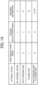
- FIG. 14 is an example of data contained in an option table.
- FIGS. 15A and 15B are diagrams each illustrating a relationship between the type of optional device installed in the in-body space 13 and the distance between the first conveyor 55 and the second conveyor 65.
- the HDD 104 stores the option table illustrated in FIG. 14 .
- the option table shows relationships between optional devices installed in the in-body space 13 and the states of a first installation signal and a second installation signal and distance information.
- the first installation signal is in a high (H) state when the hole punching unit 70 is installed, and is in a low (L) state when the hole punching unit 70 is not installed.
- the second installation signal is in a high (H) state when the folding unit 80 is installed, and is in a low (L) state when the folding unit 80 is not installed.
- the distance information refers to a distance between the output interface of the image forming device 12 and the input interface of the binding unit 30 (length in the second conveyance direction) necessary for installation of an optional device in the in-body space 13.
- the first installation signal is in the H state
- the second installation signal is in the L state.
- the conveyance path Ph2 is shortened by the length X1
- the distance between the first conveyor 55 and the second conveyor 65 in the second conveyance direction is denoted by L1.
- the controller 100 may start to drive the drive motor 55c in response to the number of pulse signals output from the rotary encoder of the drive motor 65c reaching a first predetermined number (a number corresponding to the conveyance distance L1) after the start of output of a detection signal from the sheet sensor 54.
- the first installation signal and the second installation signal are in the H state.
- the conveyance path Ph2 is shortened by the length "X1 + X2"
- the distance between the first conveyor 55 and the second conveyor 65 in the second conveyance direction is denoted by L2 ( ⁇ L1).
- the controller 100 may start to drive the drive motor 55c in response to the number of pulse signals output from the rotary encoder of the drive motor 65c reaching a second predetermined number (a number corresponding to the conveyance distance L2) after the start of output of a detection signal from the sheet sensor 54.
- the controller 100 may control the drive timings of the first conveyor 55 and the second conveyor 65 according to the length of the conveyance path Ph2 between the first conveyor 55 and the second conveyor 65.
- the sheet sensor 64 may be omitted.
- the length of the conveyance path Ph2 can be adjusted according to the size of an optional device installed in the in-body space 13.
- the degree of freedom can be improved in terms of installation space in the media conveying apparatus (50, 60) including the output tray 67 on which a large number of sheets S or sheet bundles Sb can be put.
- the second guides 63a and 63b are disposed at the ends of the second defining members 62a and 62b, it is possible to prevent the sheet S or the sheet bundle Sb passing through the conveyance path Ph2 from being stuck in the conveyance path Ph2 between the first defining members 52a and 52b and the second defining members 62a and 62b.
- the cover 61b is disposed in such a way as to face the second guides 63a and 63b, where a jam is most likely to occur in the media conveying apparatus (50, 60), the workability of jam handling is improved.
- the opening and the cover may be disposed at positions facing the first guides 53a and 53b of the first housing 51.
- the second guide 63a is rotatable in a direction away from the second guide 63b, so that the workability of jam handling is further improved.
- the second guide 63a may be made of a highly flexible material such as Mylar ® .
- occurrence of a jam is detected by the sheet sensor 64, and notification thereof is provided through the operation panel 110.
- the downtime of the image forming apparatus 10 can be shortened.
- the distance between the driving roller 55a and the driven roller 55b is adjusted by the pressing mechanism 55f, it is possible to handle the sheets S or the sheet bundles Sb having various thicknesses.
- the first conveyance unit 50 and the second conveyance unit 60 are unitized, and the entire first conveyance unit 50 is slid in the second conveyance direction.
- the configuration can be simplified as compared with a case where the components (51 to 55) of the first conveyance unit 50 are separately slid.
- the relative positions of the components (51 to 55) do not change, deterioration in conveyance accuracy can be prevented.
- the image forming apparatus 10 in which various optional devices can be installed, by installing the media conveying apparatus (50, 60) of the above embodiment in the in-body space 13.
- the media conveying apparatus (50, 60) since it is not necessary to replace the media conveying apparatus (50, 60) in accordance with the size of an optional device, the downtime of the image forming apparatus 10 can be minimized.
- the drive timings of the first conveyor 55 and the second conveyor 65 are controlled in accordance with the length of the conveyance path Ph2 to be lengthened or shortened, it is possible to reduce the number of sensors that detect the sheet S or the sheet bundle Sb. This also contributes to energy saving.
- a media conveying apparatus includes: a pair of first defining members that defines an upstream part of a conveyance path in a conveyance direction; a pair of second defining members that defines a downstream part of the conveyance path in the conveyance direction; a first conveyor that conveys a medium in the conveyance path defined by the pair of first defining members in the conveyance direction; a second conveyor that conveys the medium in the conveyance path defined by the pair of second defining members in the conveyance direction; a tray disposed downstream from the pair of second defining members in the conveyance direction, the tray to stack the medium ejected from the conveyance path; and a lift that raises and lowers the tray.
- the pair of first defining members and the pair of second defining members are movable relative to each other in the conveyance direction in such a way as to lengthen or shorten the conveyance path.
- a pair of guides is disposed at an upstream end of the pair of second defining members in the conveyance direction, a distance between the pair of guides increasing toward an upstream side in the conveyance direction.
- the media conveying apparatus of the second aspect further includes: a housing that houses the pair of second defining members and the second conveyor; and a cover that can move to a closed position to close an opening and an open position to open the opening, the housing having the opening at a position to face the pair of guides.
- one of the pair of guides is rotatable in a direction away from another of the pair of guides, a downstream end of the one of the pair of guides in the conveyance direction serving as a rotation center.
- the media conveying apparatus of the third aspect or the fourth aspect further includes: a sensor that outputs a detection signal when the medium is located between the pair of guides; and a notifier that notifies that the medium is stuck in the conveyance path in a case where output of the detection signal from the sensor is not stopped even when the second conveyor is driven by a predetermined amount after the output of the detection signal is started.
- each of the first conveyor and the second conveyor includes: a drive roller; a driven roller disposed in such a way as to face the drive roller across the conveyance path, the driven roller being to be brought into contact with and separated from the drive roller; a drive motor that generates driving force for rotating the drive roller; and a pressing mechanism that presses the driven roller against the drive roller.
- the media conveying apparatus of any one of the first aspect to the sixth aspect further includes: a first conveyance unit including a first housing that houses the pair of first defining members and the first conveyor; and a second conveyance unit including a second housing that houses the pair of second defining members, the second conveyor, and the lift, the second housing supporting the tray with an outer wall.
- the conveyance path is shortened as the first housing enters the second housing.
- an image forming apparatus includes: an image forming device that forms an image on a medium; a housing that houses the image forming device and has an in-body space; and the media conveying apparatus of any one of the first aspect to the seventh aspect, the media conveying apparatus being detachably installed in the in-body space.
- the tray moves up and down along an outer wall of the housing.
- the image forming apparatus of the eighth aspect further includes a post-processing device that is detachably installed in the in-body space, and performs post processing on the medium on which an image has been formed by the image forming device.
- the media conveying apparatus is detachably connected to the post-processing device, and conveys the medium subjected to the post processing toward the tray.
- the pair of first defining members and the pair of second defining members lengthen or shorten the conveyance path in accordance with a size of an optional device located between and connected to the image forming device and the post-processing device in the in-body space.
- the image forming apparatus of the tenth aspect further includes a controller that controls drive timings of the first conveyor and the second conveyor according to a length of the conveyance path between the first conveyor and the second conveyor.
- the present invention can be implemented in any convenient form, for example using dedicated hardware, or a mixture of dedicated hardware and software.
- the present invention may be implemented as computer software implemented by one or more networked processing apparatuses.
- the processing apparatuses include any suitably programmed apparatuses such as a general purpose computer, a personal digital assistant, a Wireless Application Protocol (WAP) or third-generation (3G)-compliant mobile telephone, and so on. Since the present invention can be implemented as software, each and every aspect of the present invention thus encompasses computer software implementable on a programmable device.
- the computer software can be provided to the programmable device using any conventional carrier medium (carrier means).
- the carrier medium includes a transient carrier medium such as an electrical, optical, microwave, acoustic or radio frequency signal carrying the computer code.
- transient medium is a Transmission Control Protocol/Internet Protocol (TCP/IP) signal carrying computer code over an IP network, such as the Internet.
- the carrier medium may also include a storage medium for storing processor readable code such as a floppy disk, a hard disk, a compact disc read-only memory (CD-ROM), a magnetic tape device, or a solid state memory device.
Landscapes
- Engineering & Computer Science (AREA)
- Mechanical Engineering (AREA)
- Physics & Mathematics (AREA)
- General Physics & Mathematics (AREA)
- Folding Of Thin Sheet-Like Materials, Special Discharging Devices, And Others (AREA)
- Pile Receivers (AREA)
- Feeding Of Articles By Means Other Than Belts Or Rollers (AREA)
- Handling Of Sheets (AREA)
- Controlling Sheets Or Webs (AREA)
- Delivering By Means Of Belts And Rollers (AREA)
Abstract
Description
- The present disclosure relates to a media conveying apparatus and an image forming apparatus.
- An image forming apparatus includes an image former, a post-processing device, and a tray. The image former forms an image on a sheet. The post-processing device performs post processing on the sheet on which an image has been formed. The sheet subjected to the post processing is to be stacked on the tray. In addition, some of such image forming apparatuses are equipped with a tray that is lifted or lowered to allow a large number of sheets to be stacked on the tray.
- As an example of such an image forming apparatus,
Japanese Unexamined Patent Application Publication No. 2021-123490 - However, the configuration disclosed in
Japanese Unexamined Patent Application Publication No. 2021-123490 - The present disclosure has been made so as to solve such a problem, and an object of the present disclosure is to provide a media conveying apparatus that includes a tray on which a large number of media can be put and has a high degree of freedom in terms of installation space.
- In order to solve the above technical problem, the present disclosure provides a media conveying apparatus that includes a pair of first defining members, a pair of second defining members, a first conveyor, a second conveyor, and a tray. The pair of first defining members defines an upstream part of a conveyance path in a conveyance direction. The pair of second defining members defines a downstream part of the conveyance path in the conveyance direction. The first conveyor conveys a medium in the upstream part in the conveyance direction. The second conveyor conveys the medium in the downstream part in the conveyance direction. The tray is disposed downstream from the pair of second defining members in the conveyance direction. The tray stacks the medium ejected from the conveyance path. The pair of first defining members and the pair of second defining members are movable relative to each other in the conveyance direction to lengthen and shorten the conveyance path including the upstream part and the downstream part.
- The present disclosure also provides an image forming apparatus that includes an image forming device, a housing, and the media conveying apparatus. The image forming device forms an image on a medium. The housing houses the image forming device and has an in-body space. The media conveying apparatus is detachably installed in the in-body space. The tray moves up and down along an outer wall of the housing.
- According to the present disclosure, it is possible to obtain a media conveying apparatus that includes a tray on which a large number of media can be put and has a high degree of freedom in terms of installation space.
- A more complete appreciation of embodiments of the present disclosure and many of the attendant advantages and features thereof can be readily obtained and understood from the following detailed description with reference to the accompanying drawings, wherein:
-
FIGS. 1A to 1C are external views of an image forming apparatus according to an embodiment of the present disclosure; -
FIG. 2A is a side view of a binding unit, which illustrates an internal configuration thereof; -
FIG. 2B is a plan view of the binding unit, which illustrates the internal configuration thereof; -
FIG. 3A is a plan view of the binding unit, which illustrates a position of a binder; -
FIG. 3B is a side view of the binding unit, which illustrates a slit; -
FIG. 4A is a diagram illustrating the binding unit in which a sheet has not yet reached a conveyance roller pair; -
FIG. 4B is a diagram illustrating the binding unit in which the sheet has reached the conveyance roller pair; -
FIGS. 5A and 5B are diagrams each illustrating a state of the binding unit performing a binding process; -
FIG. 6 is a diagram illustrating the binding unit in the state illustrated inFIG. 5B as viewed from a sheet thickness direction; -
FIGS. 7A and 7B are diagrams illustrating the binding unit in a state where a sheet bundle subjected to the binding process is ejected to an output tray; -
FIG. 8A is a side view of a media conveying apparatus in a state where the distance between a first conveyor and a second conveyor has been increased; -
FIG. 8B is a plan view of a main part of the media conveying apparatus in the same state; -
FIG. 9A is a side view of the media conveying apparatus in a state where the distance between the first conveyor and the second conveyor has been reduced; -
FIG. 9B is a plan view of the main part of the media conveying apparatus in the same state; -
FIGS. 10A and 10B are schematic diagrams illustrating a configuration of the first conveyor; -
FIGS. 11A and 11B are diagrams illustrating the periphery of a cover disposed on a second housing; -
FIG. 12A is a schematic configuration diagram of a hole punching unit; -
FIG. 12B is a schematic configuration diagram of a folding unit; -
FIG. 13 is a block diagram illustrating a hardware configuration of the image forming apparatus; -
FIG. 14 is an example of data contained in an option table; and -
FIGS. 15A and 15B are diagrams each illustrating a relationship between the type of optional device and the distance between the first conveyor and the second conveyor. - The accompanying drawings are intended to depict embodiments of the present disclosure and should not be interpreted to limit the scope thereof. The accompanying drawings are not to be considered as drawn to scale unless explicitly noted. Also, identical or similar reference numerals designate identical or similar components throughout the several views.
- In describing embodiments illustrated in the drawings, specific terminology is employed for the sake of clarity. However, the disclosure of this specification is not intended to be limited to the specific terminology so selected and it is to be understood that each specific element includes all technical equivalents that have a similar function, operate in a similar manner, and achieve a similar result.
- Referring now to the drawings, embodiments of the present disclosure are described below. As used herein, the singular forms "a," "an," and "the" are intended to include the plural forms as well, unless the context clearly indicates otherwise.
- A description is provided of an
image forming apparatus 10 according to an embodiment of the present disclosure with reference to the drawings.FIGS. 1A to 1C are external views of theimage forming apparatus 10 according to an embodiment of the present disclosure. Theimage forming apparatus 10 is an apparatus that forms an image on a sheet S which is an example of a sheet medium (typically, a sheet of paper). As illustrated inFIGS. 1A to 1C , theimage forming apparatus 10 includes ahousing 11 and animage forming device 12. - The
housing 11 has a box shape to form an internal space for accommodating components of theimage forming apparatus 10. Thehousing 11 has an in-body space 13 that is accessible from the outside of theimage forming apparatus 10. The in-body space 13 is located, for example, slightly above the center of thehousing 11 in the vertical direction. An outer wall of thehousing 11 has been cut out to expose the in-body space 13 to the outside. Furthermore, the in-body space 13 can accommodate a binding unit 30 (post-processing device), afirst conveyance unit 50 and a second conveyance unit 60 (media conveying apparatus), and ahole punching unit 70 and a folding unit 80 (optional devices). - More specifically,
FIG. 1A illustrates a state in which only the bindingunit 30 has been disposed in the in-body space 13.FIG. 1B illustrates a state in which thefirst conveyance unit 50 and thesecond conveyance unit 60 have been disposed in the in-body space 13, together with the bindingunit 30.FIG. 1C illustrates a state in which both thehole punching unit 70 and thefolding unit 80 have been disposed in the in-body space 13, together with the bindingunit 30, thefirst conveyance unit 50, and thesecond conveyance unit 60. Alternatively, one of thehole punching unit 70 and thefolding unit 80 may be disposed in the in-body space 13, together with the bindingunit 30, thefirst conveyance unit 50, and thesecond conveyance unit 60. - The
image forming device 12 forms an image on the sheet S stored in a tray, and ejects the sheet S on which the image has been formed to the bindingunit 30, thehole punching unit 70, or thefolding unit 80. Theimage forming device 12 may be an inkjet image forming device that forms an image with ink, or may be an electrophotographic image forming device that forms an image with toner. Since theimage forming device 12 has a known configuration, a detailed description of the configuration of theimage forming device 12 is omitted. - The
hole punching unit 70 and thefolding unit 80 are installed in the in-body space 13 of theimage forming apparatus 10 such that thehole punching unit 70 and thefolding unit 80 are located downstream from theimage forming device 12 and upstream from the bindingunit 30 on a conveyance path (a path indicated by a dashed arrow in each ofFIGS. 1A to 1C ) of the sheet S from theimage forming device 12 to the bindingunit 30. That is, the sheet S on which an image has been formed by theimage forming device 12 is subjected to one or both of a hole punching process (described below) by thehole punching unit 70 and a folding process (described below) by thefolding unit 80, and is then delivered to the bindingunit 30 and subjected to a binding process to be described below. - The
hole punching unit 70 and thefolding unit 80 are detachably installed in theimage forming apparatus 10. When thehole punching unit 70 and thefolding unit 80 are removed, the sheet S on which an image has been formed by theimage forming device 12 is directly delivered to the bindingunit 30 and subjected to the binding process. Furthermore, another optional device such as a liquid applying unit is detachably installed at a location in the in-body space 13 where thehole punching unit 70 and thefolding unit 80 were disposed before being removed. - When the liquid applying unit is installed, the sheet S on which the image has been formed by the
image forming device 12 is first delivered to the liquid applying unit and subjected to a liquid applying process, and is then delivered to the bindingunit 30 and subjected to the binding process. The liquid applying process refers to a process of applying liquid to a binding position on the surface of the sheet S at which the sheet S is to be bound by the bindingunit 30. Note that any optional device other than the liquid applying unit may be installed at the location in the in-body space 13 where thehole punching unit 70 and thefolding unit 80 were disposed before being removed, so as to perform a desired process on the sheet S. Optional devices may be omitted. - Furthermore, each of the binding
unit 30, thefirst conveyance unit 50, thesecond conveyance unit 60, thehole punching unit 70, thefolding unit 80, and the liquid applying unit is unitized, to which an input-output interface of the sheet S can be connected. That is, in theimage forming apparatus 10, the bindingunit 30, thehole punching unit 70, thefolding unit 80, and the liquid applying unit are replaceable according to the intended use of theimage forming apparatus 10. - More specifically, input interfaces of the binding
unit 30, thehole punching unit 70, thefolding unit 80, and the liquid applying unit can be connected to an output interface of theimage forming device 12. The input interface of the bindingunit 30 can also be connected to thehole punching unit 70, thefolding unit 80, and the liquid applying unit. An output interface of the bindingunit 30 can be connected to an input interface of thefirst conveyance unit 50. Furthermore, an input interface of thesecond conveyance unit 60 can be connected to an output interface of thefirst conveyance unit 50. Adjacent units are detachably connected to each other by a mechanical lock, a magnet, or the like. The units installed in the in-body space 13 are each connected to a controller 100 (seeFIG. 13 ) by a harness for transmitting and receiving various signals. -
FIG. 2A is a side view of the bindingunit 30, which illustrates an internal configuration thereof.FIG. 2B is a plan view of the bindingunit 30, which illustrates the internal configuration thereof.FIG. 3A is a plan view of the bindingunit 30, which illustrates a position of abinder 42.FIG. 3B is a side view of the bindingunit 30, which illustrates aslit 31a. The bindingunit 30 performs the binding process (post processing) of binding a plurality of sheets S (sheet bundle Sb) on which images have been formed by theimage forming device 12. However, a specific example of the post-processing device is not limited to the bindingunit 30. As illustrated inFIGS. 2A, 2B ,3A, and 3B , the bindingunit 30 includes abinding case 31, anoutput tray 32, a plurality of conveyance roller pairs 33, 34, 35, and 36, aninternal tray 37, a tappingroller 38, returnrollers 39,end fences side fences binder 42. - The binding
case 31 has a box shape to form an internal space for accommodating the components (33 to 42) of the bindingunit 30. A conveyance path Ph1 is formed in the internal space of the bindingcase 31. The conveyance path Ph1 is a space through which the sheet S passes. Theoutput tray 32 is supported on an outer surface of the bindingcase 31. The sheet S or the sheet bundle Sb conveyed by the conveyance roller pairs 33 to 36 is stacked on theoutput tray 32. - The conveyance roller pairs 33 to 36 are arranged on the conveyance path Ph1 at predetermined intervals. The conveyance roller pairs 33 to 36 convey the sheet S along the conveyance path Ph1. The
conveyance roller pair 33 includes a drivingroller 33a and a drivenroller 33b disposed in such a way as to face each other across the conveyance path Ph1. The drivingroller 33a and the drivenroller 33b are rotatably supported by the bindingcase 31. The rotary drive force of a conveyance motor is transmitted to the drivingroller 33a to rotate the drivingroller 33a forward in a direction of conveying the sheet S (clockwise direction inFIGS. 2A and 2B ). The drivenroller 33b is disposed in such a way as to face the drivingroller 33a across the conveyance path Ph1, and is driven by rotation of the drivingroller 33a. Driving the conveyance motor causes the sheet S nipped by the drivingroller 33a and the drivenroller 33b to be conveyed along the conveyance path Ph1. - The conveyance roller pairs 34 to 36 each have a basic configuration in common with the
conveyance roller pair 33. However, theconveyance roller pair 36 includes a drivingroller 36a and a drivenroller 36b that can be brought into contact with and separated from the drivingroller 36a. Theconveyance roller pair 35 may be slidable in the width direction so as to implement a sorting process in which the sheets S are shifted in the width direction and ejected to theoutput tray 32. - The
internal tray 37 temporarily supports the plurality of sheets S conveyed by theconveyance roller pair 36. The tappingroller 38 is supported at an end of a rotation arm above theinternal tray 37. As the rotation arm is rotated, the tappingroller 38 supplies the sheet S nipped by theconveyance roller pair 36 to theinternal tray 37. Thereturn rollers 39 rotate in contact with the upper surface of the sheet S supported by theinternal tray 37 to guide the sheet S toward theconveyance roller pair 36. Hereinafter, a direction from theconveyance roller pair 36 toward theend fences internal tray 37 is referred to as a "main scanning direction". - The
end fences internal tray 37 in the first conveyance direction, and align positions of the sheets S in the first conveyance direction. Theside fences internal tray 37 to align positions of the sheets S in the main scanning direction. - The
binder 42 is disposed at a downstream end of the sheet bundle Sb supported by theinternal tray 37 in the first conveyance direction. Thebinder 42 is movable along the sheet bundle Sb supported by theinternal tray 37 in the main scanning direction orthogonal to the first conveyance direction. As an example, thebinder 42 is a press-bonding binder that presses and deforms the sheet bundle Sb to bind the sheet bundle Sb. As another example, thebinder 42 is a needle binder that causes a binding needle to penetrate the sheet bundle Sb and binds the sheet bundle Sb. As still another example, the bindingunit 30 may include both the press-bonding binder and the needle binder. - As illustrated in
FIGS. 3A and 3B , theslit 31a for manual binding is provided at a position facing thebinder 42 of the bindingcase 31. A corner of the sheet bundle Sb inserted into the bindingcase 31 through theslit 31a can be manually bound by thebinder 42. The bindingcase 31 further includesguide walls slit 31a. Theguide wall 31b performs the positioning of the sheet bundle Sb to be manually bound (that is, the sheet bundle Sb having a corner to be inserted into theslit 31a) in the first conveyance direction. Theguide wall 31c performs the positioning of the sheet bundle Sb to be manually bound (that is, the sheet bundle Sb having a corner to be inserted into theslit 31a) in the main scanning direction. - Next, the binding process will be described with reference to
FIGS. 4A to 7B .FIG. 4A is a diagram illustrating the bindingunit 30 in which the sheet S has not yet reached theconveyance roller pair 36, andFIG. 4B is a diagram illustrating the bindingunit 30 in which the sheet S has reached theconveyance roller pair 36.FIGS. 5A and 5B are diagrams each illustrating a state of the bindingunit 30 performing the binding process.FIG. 6 is a diagram illustrating the bindingunit 30 in the state illustrated inFIG. 5B as viewed from the thickness direction of the sheet S.FIGS. 7A and 7B are diagrams illustrating the bindingunit 30 in a state where the sheet bundle Sb subjected to the binding process is ejected to theoutput tray 32. - As illustrated in
FIGS. 4A and 4B , the bindingunit 30 rotates the conveyance roller pairs 33 to 35 in the forward direction to convey the sheet S supplied from theimage forming device 12 along the conveyance path Ph1. At this time, the drivingroller 36a and the drivenroller 36b of theconveyance roller pair 36 are separated from each other. - Next, as illustrated in
FIGS. 5A and 5B , the bindingunit 30 brings the tappingrollers 38 into contact with the sheet S having passed through theconveyance roller pair 35, and rotates the tappingrollers 38 to store the sheet S in theinternal tray 37. In the bindingunit 30, theside fences FIG. 6 to align, in the width direction, positions of the sheets S stored in theinternal tray 37. - Thus, the binding
unit 30 forms the sheet bundle Sb on theinternal tray 37 by repeating the process illustrated inFIGS. 4A to 6 . Next, the bindingunit 30 causes thebinder 42 to face a binding position of the sheet bundle Sb in response to a predetermined number of sheets S being stacked on theinternal tray 37. Then, the bindingunit 30 drives thebinder 42 to bind the sheet bundle Sb supported by theinternal tray 37. - Next, as illustrated in
FIG. 7A , the bindingunit 30 brings thereturn rollers 39 into contact with the press-bonded sheet bundle Sb, and rotates thereturn rollers 39 to cause the sheet bundle Sb to be nipped by the drivingroller 36a and the drivenroller 36b. Then, as illustrated inFIG. 7B , the bindingunit 30 rotates theconveyance roller pair 36 in the forward direction to eject the sheet bundle Sb to theoutput tray 32. - Next, a configuration of the media conveying apparatus will be described with reference to
FIGS. 8A to 11B .FIG. 8A is a side view of the media conveying apparatus in a state where the distance between afirst conveyor 55 and asecond conveyor 65 has been increased.FIG. 8B is a plan view of a main part of the media conveying apparatus in the same state.FIG. 9A is a side view of the media conveying apparatus in a state where the distance between thefirst conveyor 55 and thesecond conveyor 65 has been reduced.FIG. 9B is a plan view of the main part of the media conveying apparatus in the same state. - As illustrated in
FIGS. 8A, 8B ,9A, and 9B , the media conveying apparatus according to the present embodiment includes thefirst conveyance unit 50 and thesecond conveyance unit 60. Therefore, in the present specification, the media conveying apparatus is referred to as a "media conveying apparatus (50, 60)". Thefirst conveyance unit 50 is disposed upstream from thesecond conveyance unit 60 in the second conveyance direction. Hereinafter, a direction from thefirst conveyance unit 50 toward thesecond conveyance unit 60 along a conveyance path Ph2 formed inside the media conveying apparatus (50, 60) is referred to as a "second conveyance direction". - The media conveying apparatus (50, 60) can be detachably installed in the in-body space. The input interface of the media conveying apparatus (50, 60) can be connected to the output interface of the binding
unit 30. More specifically, the media conveying apparatus (50, 60) is connected to the output interface of the bindingunit 30 from which theoutput tray 32 has been removed. The media conveying apparatus (50, 60) has a function of putting a large number of sheets S or sheet bundles Sb ejected from the bindingunit 30 on anoutput tray 67. - The
first conveyance unit 50 mainly includes afirst housing 51, a pair of first definingmembers first guides sheet sensor 54, and thefirst conveyor 55. Thefirst housing 51 has a box shape to form an internal space for accommodating the components (52 to 55) of thefirst conveyance unit 50. - The pair of first defining
members first housing 51. An upstream part of the conveyance path Ph2 in the second conveyance direction is formed between the pair of first definingmembers members - The pair of
first guides members first guides first guides first guides unit 30 to a space between the pair of first definingmembers - The
sheet sensor 54 is installed at an upstream end of the conveyance path Ph2 defined by the pair of first definingmembers first guides sheet sensor 54 outputs a detection signal to thecontroller 100 when the sheet S is located at an installation position (that is, located between the pair offirst guides sheet sensor 54. -
FIGS. 10A and 10B are schematic diagrams illustrating a configuration of thefirst conveyor 55. As illustrated inFIGS. 10A and 10B , thefirst conveyor 55 is disposed downstream from thesheet sensor 54 in the second conveyance direction. Thefirst conveyor 55 conveys the sheet S or the sheet bundle Sb in the second conveyance direction in the conveyance path Ph2 defined by the pair of first definingmembers first conveyor 55 includes, for example, a drivingroller 55a, a drivenroller 55b, adrive motor 55c, a drivingforce transmission mechanism 55d, anarm 55e, and apressing mechanism 55f. - The driving
roller 55a is disposed on one side of the conveyance path Ph2 in the thickness direction (on the same side as the first definingmember 52a in the present embodiment). The drivenroller 55b is disposed on the other side of the conveyance path Ph2 in the thickness direction (on the same side as the first definingmember 52b in the present embodiment). That is, the drivingroller 55a and the drivenroller 55b are disposed in such a way as to face each other across the conveyance path Ph2. The drivingroller 55a and the drivenroller 55b nip the sheet S or the sheet bundle Sb in the conveyance path Ph2 defined by the pair of first definingmembers - The
drive motor 55c generates driving force for rotating the drivingroller 55a. The driving force of thedrive motor 55c is transmitted to the drivingroller 55a via the drivingforce transmission mechanism 55d. The drivingforce transmission mechanism 55d includes a gear, a pulley, a timing belt, or a combination thereof. As a result, the drivingroller 55a rotates in a direction (counterclockwise direction inFIGS. 10A and 10B ) in which the sheet S or the sheet bundle Sb in the conveyance path Ph2 is conveyed in the second conveyance direction. The drivenroller 55b is driven by rotation of the drivingroller 55a. The drivingroller 55a and the drivenroller 55b nip the sheet S or the sheet bundle Sb in the conveyance path Ph2, and rotate to convey the sheet S or the sheet bundle Sb in the second conveyance direction. - The
arm 55e rotatably supports the drivenroller 55b. Thearm 55e rotates in a direction in which the drivenroller 55b comes into contact with the drivingroller 55a and in a direction in which the drivenroller 55b separates from the drivingroller 55a. Thepressing mechanism 55f presses the drivenroller 55b against the drivingroller 55a. The magnitude of pressing force to be generated by thepressing mechanism 55f is set such that the drivenroller 55b can be brought into contact with and separated from the drivingroller 55a according to the thickness of the sheet S or the sheet bundle Sb entering a space between the drivingroller 55a and the drivenroller 55b, and that the drivingroller 55a and the drivenroller 55b can nip and convey the sheet S or the sheet bundle Sb. As a result, the distance between the drivingroller 55a and the drivenroller 55b is adjusted according to the thickness of the sheet S or the sheet bundle Sb in the conveyance path Ph2. That is, thefirst conveyor 55 can convey the sheets S or the sheet bundles Sb having different thicknesses. - The
second conveyance unit 60 mainly includes asecond housing 61, a pair of second definingmembers second guides sheet sensor 64, thesecond conveyor 65, asecond conveyor 66, theoutput tray 67, and a lift 68. Thesecond housing 61 has a box shape to form an internal space for accommodating the components (62 to 66, 68) of thesecond conveyance unit 60. In addition, thesecond housing 61 supports theoutput tray 67 with an outer wall in such a way as to allow theoutput tray 67 to be raised and lowered. More specifically, when thesecond conveyance unit 60 is installed in the in-body space 13, a portion of thesecond housing 61 that supports theoutput tray 67 is disposed along an outer surface of thehousing 11 outside the in-body space 13 as illustrated inFIGS. 1B and 1C . - The pair of second defining
members second housing 61. A downstream part of the conveyance path Ph2 in the second conveyance direction is formed between the pair of second definingmembers members members members - The pair of first defining
members members - The pair of
second guides members second guides second guides second guides first conveyance unit 50 to a space between the pair of second definingmembers - The
sheet sensor 64 is installed at an upstream end of the conveyance path Ph2 defined by the pair of second definingmembers second guides sheet sensor 64 outputs a detection signal to thecontroller 100 when the sheet S is located at an installation position (that is, located between the pair ofsecond guides sheet sensor 64. - The
second conveyors sheet sensor 64 in the second conveyance direction. Thesecond conveyors second conveyors common drive motor 65c. Thesecond conveyors members second conveyors first conveyor 55 illustrated inFIGS. 10A and 10B , for example. - The
output tray 67 is supported on an outer surface of thesecond housing 61 on the downstream side of the pair of second definingmembers output tray 67 is disposed below a downstream end (outlet) of the conveyance path Ph2 in the second conveyance direction. Theoutput tray 67 can be raised and lowered along the outer surface of thesecond housing 61. The sheet S or the sheet bundle Sb ejected from the conveyance path Ph2 by thesecond conveyors output tray 67. - The lift 68 raises and lowers the
output tray 67. The lift 68 includes, for example, pulleys 68a and 68b, atiming belt 68c that is an endless annular belt, and a liftingmotor 68d. Thepulleys second housing 61. Thetiming belt 68c is stretched around thepulleys motor 68d generates driving force for rotating thepulley 68a (raising and lowering the output tray 67). As a result, theoutput tray 67 moves up and down which is coupled to thetiming belt 68c circulating around thepulleys -
FIGS. 11A and 11B are diagrams illustrating the periphery of acover 61b disposed on thesecond housing 61. As illustrated inFIG. 11B , anopening 61a is formed in a side wall of thesecond housing 61. Theopening 61a penetrates the side wall of thesecond housing 61 at a position facing the pair ofsecond guides second housing 61 includes thecover 61b that can move (rotate in the present embodiment) to a closed position (FIG. 11A ) and an open position (FIG. 11B ). Thecover 61b closes theopening 61a at the closed position, and opens theopening 61a at the open position. - Furthermore, one (the lower
second guide 63a in the present embodiment) of the pair ofsecond guides second guide 63b in the present embodiment) of the pair ofsecond guides second guides second guides second guide 63a is rotated in a direction away from thesecond guide 63b, and thecover 61b is moved to the open position. Thus, the sheet S or sheet bundle Sb that has caused the jam can be removed. - As illustrated in
FIGS. 8B and9B , thefirst housing 51 of thefirst conveyance unit 50 is slidably supported by a guide rod 56 (slide mechanism) extending in the second conveyance direction in the in-body space 13. That is, thefirst conveyor 55 is slidable in the second conveyance direction along theguide rod 56. More specifically, thefirst conveyance unit 50 moves in a direction in which thefirst conveyance unit 50 comes into contact with thesecond conveyance unit 60 and in a direction in which thefirst conveyance unit 50 moves away from thesecond conveyance unit 60, without changing the relative positions of the components (51 to 55). The bindingunit 30 may be movable along theguide rod 56 together with thefirst conveyance unit 50. - As illustrated in
FIGS. 8A and 8B , when thefirst conveyance unit 50 slides in a direction away from thesecond conveyance unit 60, the conveyance path Ph2 (in other words, the distance between thefirst conveyor 55 and the second conveyor 65) is lengthened. As a result, the input interface of the bindingunit 30 can be connected to the output interface of theimage forming device 12 as illustrated inFIG. 1B . When the distance between thefirst conveyance unit 50 and thesecond conveyance unit 60 is maximized, the downstream end of the pair of first definingmembers members second guides - Meanwhile, as illustrated in
FIGS. 9A and 9B , when thefirst conveyance unit 50 slides in a direction in which thefirst conveyance unit 50 approaches thesecond conveyance unit 60, the conveyance path Ph2 (in other words, the distance between thefirst conveyor 55 and the second conveyor 65) is shortened. At this time, thefirst housing 51 enters thesecond housing 61, and the pair of first definingmembers members hole punching unit 70 and thefolding unit 80 is formed between the output interface of theimage forming device 12 and the input interface of the bindingunit 30 as illustrated inFIG. 1C . Note that thefirst conveyance unit 50 may be manually slid by a user of theimage forming apparatus 10, or may be slid by the driving force of a slide motor. - In the present embodiment, an example has been described in which the
second conveyance unit 60 is fixed and thefirst conveyance unit 50 is slid in the second conveyance direction. As another example, thefirst conveyance unit 50 may be fixed, and thesecond conveyance unit 60 may be slid in the second conveyance direction. As still another example, both thefirst conveyance unit 50 and thesecond conveyance unit 60 may be slid in the second conveyance direction. That is, thefirst conveyance unit 50 and the second conveyance unit 60 (more specifically, the pair of first definingmembers members first conveyance unit 50 and thesecond conveyance unit 60 can move relative to each other in the second conveyance direction in such a way as to lengthen or shorten the conveyance path Ph2. - Next, configurations of the
hole punching unit 70 and thefolding unit 80 will be described with reference toFIGS. 12A and 12B. FIG. 12A is a schematic configuration diagram of thehole punching unit 70.FIG. 12B is a schematic configuration diagram of thefolding unit 80. Since the configurations of thehole punching unit 70 and thefolding unit 80 are already known, detailed description thereof is omitted, but for example, the following configurations are conceivable. - As illustrated in
FIG. 12A , thehole punching unit 70 includes ahousing 71, asheet sensor 72, a punch pin 73, and apunch chad container 74. Thehousing 71 has a box shape to form an internal space for accommodating the components of thehole punching unit 70. A conveyance path Ph3 is formed in the internal space of thehousing 71. The sheet S on which an image has been formed by theimage forming device 12 passes through the conveyance path Ph3. Thesheet sensor 72 detects that the sheet S supplied from theimage forming device 12 has reached a predetermined position. The punch pin 73 punches a hole in the sheet S detected by thesheet sensor 72. Punch chads that have fallen off from the sheet S fall into thepunch chad container 74. Thus, thehole punching unit 70 implements the punching process for punching a hole in the sheet S. - The
folding unit 80 performs the folding process in which the sheet S on which an image has been formed by theimage forming device 12 is folded into a predetermined shape (for example, Z fold, letter fold-out, or half fold). As illustrated inFIG. 12B , thefolding unit 80 includes ahousing 81, aconveyance roller pair 82, afirst folding roller 83, asecond folding roller 84, and athird folding roller 85. - The
housing 81 has a box shape to form an internal space for accommodating the components of thefolding unit 80. A main conveyance path Ph4 and a return conveyance path Ph5 are formed in the internal space of thehousing 81. The main conveyance path Ph4 and the return conveyance path Ph5 are spaces through which the sheet S passes. Theconveyance roller pair 82 conveys the sheet S along the main conveyance path Ph4. Thefirst folding roller 83 is rotatably supported by thehousing 81 at a position facing the main conveyance path Ph4. Thesecond folding roller 84 is rotatably supported by thehousing 81 at a position facing both the main conveyance path Ph4 and the return conveyance path Ph5. Thethird folding roller 85 is rotatably supported by thehousing 81 at a position facing the return conveyance path Ph5. - The
folding unit 80 rotates theconveyance roller pair 82, thefirst folding roller 83, and thesecond folding roller 84 in the forward direction. Next, thefolding unit 80 rotates theconveyance roller pair 82 in the forward direction, and rotates thefirst folding roller 83, thesecond folding roller 84, and thethird folding roller 85 in the reverse direction. As a result, the sheet S enters the return conveyance path Ph5 with a folding position at the head, and is nipped by thesecond folding roller 84 and thethird folding roller 85. As a result, the sheet S is folded at the folding position. Next, thefolding unit 80 rotates theconveyance roller pair 82, thefirst folding roller 83, and thesecond folding roller 84 in the forward direction at a timing when the rear end of the sheet S passes through the nipping position of thesecond folding roller 84 and thethird folding roller 85. As a result, the sheet S is ejected from thefolding unit 80 with the folding position at the head. -
FIG. 13 is a block diagram illustrating a hardware configuration of theimage forming apparatus 10. As illustrated inFIG. 13 , theimage forming apparatus 10 has a configuration in which a central processing unit (CPU) 101, a random access memory (RAM) 102, a read only memory (ROM) 103, a hard disk drive (HDD) 104, and an interface (I/F) 105 are connected via acommon bus 109. - The
CPU 101 is an arithmetic unit, and controls the overall operation of theimage forming apparatus 10. TheRAM 102 is a volatile storage medium that allows data to be read and written at high speed. TheCPU 101 uses theRAM 102 as a work area for data processing. TheROM 103 is a read-only non-volatile storage medium that stores programs such as firmware. TheHDD 104 is a non-volatile storage medium that allows data to be read and written and has a relatively large storage capacity. TheHDD 104 stores, e.g., an operating system (OS), various control programs, and application programs. - By an arithmetic function of the
CPU 101, theimage forming apparatus 10 processes, for example, a control program stored in theROM 103 and an information processing program (application program) loaded into theRAM 102 from a storage medium such as theHDD 104. Such processing configures a software controller including various functional modules of theimage forming apparatus 10. The software controller thus configured cooperates with hardware resources of theimage forming apparatus 10 to construct functional blocks that implement functions of theimage forming apparatus 10. That is, theCPU 101, theRAM 102, theROM 103, and theHDD 104 form thecontroller 100 that controls operation of theimage forming apparatus 10. - The I/
F 105 is an interface that connects theimage forming device 12, the bindingunit 30, thefirst conveyance unit 50, thesecond conveyance unit 60, thehole punching unit 70, thefolding unit 80, and anoperation panel 110 to thecommon bus 109. Thecontroller 100 causes, through the I/F 105, theimage forming device 12, the bindingunit 30, thefirst conveyance unit 50, thesecond conveyance unit 60, thehole punching unit 70, thefolding unit 80, and theoperation panel 110 to operate. - The
operation panel 110 includes an operation device that receives instructions from a user and a display serving as a notifier that notifies the user of information. The operation device includes, for example, physical input buttons and a touch panel overlaid on a display. Theoperation panel 110 acquires information from an operator through the operation device, and provides the operator with information through the display. A specific example of the notifier is not limited to the display, and may be a light emitting diode (LED) lamp or a speaker. - The
controller 100 controls conveyance of the sheet S or the sheet bundle Sb based on detection signals output from thesheet sensors drive motors controller 100 causes thedrive motor 55c to rotate, in response to the start of output of a detection signal from thesheet sensor 54. As a result, the sheet S or the sheet bundle Sb supplied from the bindingunit 30 is nipped by thefirst conveyor 55, conveyed in the second conveyance direction, and supplied to thesecond conveyance unit 60. In addition, thecontroller 100 causes thedrive motor 65c to rotate, in response to the start of output of a detection signal from thesheet sensor 64. As a result, the sheet S or the sheet bundle Sb is nipped by thesecond conveyors output tray 67. - In addition, the
controller 100 starts to count pulse signals output from the rotary encoder of thedrive motor 55c, in response to the start of output of a detection signal from thesheet sensor 54. In a case where the output of the detection signal from thesheet sensor 54 is not stopped even if the number of counted pulse signals reaches a predetermined value (that is, even if thefirst conveyor 55 is driven by a predetermined amount), thecontroller 100 determines that the sheet S or the sheet bundle Sb is stuck between the pair of first definingmembers operation panel 110. - Similarly, the
controller 100 starts to count pulse signals output from the rotary encoder of thedrive motor 65c, in response to the start of output of a detection signal from thesheet sensor 64. In a case where the output of the detection signal from thesheet sensor 64 is not stopped even if the number of counted pulse signals reaches a predetermined value (that is, even if thesecond conveyor 65 is driven by a predetermined amount), thecontroller 100 determines that the sheet S or the sheet bundle Sb is stuck between the pair of second definingmembers operation panel 110. - Next, a description will be given of conveyance control to be performed by the
controller 100 according to the type of optional device installed in the in-body space 13.FIG. 14 is an example of data contained in an option table.FIGS. 15A and 15B are diagrams each illustrating a relationship between the type of optional device installed in the in-body space 13 and the distance between thefirst conveyor 55 and thesecond conveyor 65. - The
HDD 104 stores the option table illustrated inFIG. 14 . The option table shows relationships between optional devices installed in the in-body space 13 and the states of a first installation signal and a second installation signal and distance information. The first installation signal is in a high (H) state when thehole punching unit 70 is installed, and is in a low (L) state when thehole punching unit 70 is not installed. The second installation signal is in a high (H) state when thefolding unit 80 is installed, and is in a low (L) state when thefolding unit 80 is not installed. The distance information refers to a distance between the output interface of theimage forming device 12 and the input interface of the binding unit 30 (length in the second conveyance direction) necessary for installation of an optional device in the in-body space 13. - As an example, in a case where only the
hole punching unit 70 is installed as an optional device, as illustrated inFIG. 15A , the first installation signal is in the H state, and the second installation signal is in the L state. At this time, it is necessary to shorten the conveyance path Ph2 by a length X1 so as to install the optional device. When the conveyance path Ph2 is shortened by the length X1, the distance between thefirst conveyor 55 and thesecond conveyor 65 in the second conveyance direction is denoted by L1. Therefore, thecontroller 100 may start to drive thedrive motor 55c in response to the number of pulse signals output from the rotary encoder of thedrive motor 65c reaching a first predetermined number (a number corresponding to the conveyance distance L1) after the start of output of a detection signal from thesheet sensor 54. - As another example, in a case where both the
hole punching unit 70 and thefolding unit 80 are installed as optional devices, as illustrated inFIG. 15B , the first installation signal and the second installation signal are in the H state. At this time, it is necessary to shorten the conveyance path Ph2 by a length "X1 + X2" so as to install the optional devices. When the conveyance path Ph2 is shortened by the length "X1 + X2", the distance between thefirst conveyor 55 and thesecond conveyor 65 in the second conveyance direction is denoted by L2 (< L1). Therefore, thecontroller 100 may start to drive thedrive motor 55c in response to the number of pulse signals output from the rotary encoder of thedrive motor 65c reaching a second predetermined number (a number corresponding to the conveyance distance L2) after the start of output of a detection signal from thesheet sensor 54. - As described above, the
controller 100 may control the drive timings of thefirst conveyor 55 and thesecond conveyor 65 according to the length of the conveyance path Ph2 between thefirst conveyor 55 and thesecond conveyor 65. In this case, thesheet sensor 64 may be omitted. - According to the above embodiment of the present disclosure, for example, the following operational effects can be obtained.
- According to the above embodiment, the length of the conveyance path Ph2 can be adjusted according to the size of an optional device installed in the in-
body space 13. Thus, the degree of freedom can be improved in terms of installation space in the media conveying apparatus (50, 60) including theoutput tray 67 on which a large number of sheets S or sheet bundles Sb can be put. - According to the above embodiment, since the
second guides members members members - According to the above embodiment, since the
cover 61b is disposed in such a way as to face thesecond guides first guides first housing 51. - According to the above embodiment, the
second guide 63a is rotatable in a direction away from thesecond guide 63b, so that the workability of jam handling is further improved. Instead of making thesecond guide 63a rotatable, thesecond guide 63a may be made of a highly flexible material such as Mylar®. - According to the above embodiment, occurrence of a jam is detected by the
sheet sensor 64, and notification thereof is provided through theoperation panel 110. As a result, the downtime of theimage forming apparatus 10 can be shortened. - Furthermore, according to the above embodiment, since the distance between the driving
roller 55a and the drivenroller 55b is adjusted by thepressing mechanism 55f, it is possible to handle the sheets S or the sheet bundles Sb having various thicknesses. - According to the above embodiment, the
first conveyance unit 50 and thesecond conveyance unit 60 are unitized, and the entirefirst conveyance unit 50 is slid in the second conveyance direction. Thus, the configuration can be simplified as compared with a case where the components (51 to 55) of thefirst conveyance unit 50 are separately slid. In addition, since the relative positions of the components (51 to 55) do not change, deterioration in conveyance accuracy can be prevented. - Furthermore, it is possible to obtain the
image forming apparatus 10 in which various optional devices can be installed, by installing the media conveying apparatus (50, 60) of the above embodiment in the in-body space 13. In addition, since it is not necessary to replace the media conveying apparatus (50, 60) in accordance with the size of an optional device, the downtime of theimage forming apparatus 10 can be minimized. - Furthermore, according to the above embodiment, since the drive timings of the
first conveyor 55 and thesecond conveyor 65 are controlled in accordance with the length of the conveyance path Ph2 to be lengthened or shortened, it is possible to reduce the number of sensors that detect the sheet S or the sheet bundle Sb. This also contributes to energy saving. - The present disclosure is not limited to the specific embodiment described above, and numerous additional modifications and variations are possible in light of the teachings within the technical scope of the present disclosure. It is therefore to be understood that the above-described embodiment of the present disclosure may be practiced otherwise by those skilled in the art than as specifically described herein. Such modifications and variations are included in the technical scope described in the appended claims.
- Aspects of the present disclosure are, for example, as follows.
- According to a first aspect, a media conveying apparatus includes: a pair of first defining members that defines an upstream part of a conveyance path in a conveyance direction; a pair of second defining members that defines a downstream part of the conveyance path in the conveyance direction; a first conveyor that conveys a medium in the conveyance path defined by the pair of first defining members in the conveyance direction; a second conveyor that conveys the medium in the conveyance path defined by the pair of second defining members in the conveyance direction; a tray disposed downstream from the pair of second defining members in the conveyance direction, the tray to stack the medium ejected from the conveyance path; and a lift that raises and lowers the tray. The pair of first defining members and the pair of second defining members are movable relative to each other in the conveyance direction in such a way as to lengthen or shorten the conveyance path.
- According to a second aspect, in the media conveying apparatus of the first aspect, a pair of guides is disposed at an upstream end of the pair of second defining members in the conveyance direction, a distance between the pair of guides increasing toward an upstream side in the conveyance direction.
- According to a third aspect, the media conveying apparatus of the second aspect, further includes: a housing that houses the pair of second defining members and the second conveyor; and a cover that can move to a closed position to close an opening and an open position to open the opening, the housing having the opening at a position to face the pair of guides.
- According to a fourth aspect, in the media conveying apparatus of the third aspect, one of the pair of guides is rotatable in a direction away from another of the pair of guides, a downstream end of the one of the pair of guides in the conveyance direction serving as a rotation center.
- According to a fifth aspect, the media conveying apparatus of the third aspect or the fourth aspect, further includes: a sensor that outputs a detection signal when the medium is located between the pair of guides; and a notifier that notifies that the medium is stuck in the conveyance path in a case where output of the detection signal from the sensor is not stopped even when the second conveyor is driven by a predetermined amount after the output of the detection signal is started.
- According to a sixth aspect, in the media conveying apparatus of any one of the first aspect to the fifth aspect, each of the first conveyor and the second conveyor includes: a drive roller; a driven roller disposed in such a way as to face the drive roller across the conveyance path, the driven roller being to be brought into contact with and separated from the drive roller; a drive motor that generates driving force for rotating the drive roller; and a pressing mechanism that presses the driven roller against the drive roller.
- According to a seventh aspect, the media conveying apparatus of any one of the first aspect to the sixth aspect, further includes: a first conveyance unit including a first housing that houses the pair of first defining members and the first conveyor; and a second conveyance unit including a second housing that houses the pair of second defining members, the second conveyor, and the lift, the second housing supporting the tray with an outer wall. The conveyance path is shortened as the first housing enters the second housing.
- According to an eighth aspect, an image forming apparatus includes: an image forming device that forms an image on a medium; a housing that houses the image forming device and has an in-body space; and the media conveying apparatus of any one of the first aspect to the seventh aspect, the media conveying apparatus being detachably installed in the in-body space. The tray moves up and down along an outer wall of the housing.
- According to a ninth aspect, the image forming apparatus of the eighth aspect further includes a post-processing device that is detachably installed in the in-body space, and performs post processing on the medium on which an image has been formed by the image forming device. The media conveying apparatus is detachably connected to the post-processing device, and conveys the medium subjected to the post processing toward the tray.
- According to a tenth aspect, in the image forming apparatus of the ninth aspect, the pair of first defining members and the pair of second defining members lengthen or shorten the conveyance path in accordance with a size of an optional device located between and connected to the image forming device and the post-processing device in the in-body space.
- According to an eleventh aspect, the image forming apparatus of the tenth aspect, further includes a controller that controls drive timings of the first conveyor and the second conveyor according to a length of the conveyance path between the first conveyor and the second conveyor.
- The present invention can be implemented in any convenient form, for example using dedicated hardware, or a mixture of dedicated hardware and software. The present invention may be implemented as computer software implemented by one or more networked processing apparatuses. The processing apparatuses include any suitably programmed apparatuses such as a general purpose computer, a personal digital assistant, a Wireless Application Protocol (WAP) or third-generation (3G)-compliant mobile telephone, and so on. Since the present invention can be implemented as software, each and every aspect of the present invention thus encompasses computer software implementable on a programmable device. The computer software can be provided to the programmable device using any conventional carrier medium (carrier means). The carrier medium includes a transient carrier medium such as an electrical, optical, microwave, acoustic or radio frequency signal carrying the computer code. An example of such a transient medium is a Transmission Control Protocol/Internet Protocol (TCP/IP) signal carrying computer code over an IP network, such as the Internet. The carrier medium may also include a storage medium for storing processor readable code such as a floppy disk, a hard disk, a compact disc read-only memory (CD-ROM), a magnetic tape device, or a solid state memory device.
Claims (12)
- A media conveying apparatus (50, 60), comprising:a pair of first defining members (52a, 52b) defining an upstream part of a conveyance path in a conveyance direction;a pair of second defining members (62a, 62b) defining a downstream part of the conveyance path in the conveyance direction;a first conveyor (55) to convey a medium in the upstream part defined by the pair of first defining members (52a, 52b) in the conveyance direction;a second conveyor (65, 66) to convey the medium in the downstream part defined by the pair of second defining members (62a, 62b) in the conveyance direction; anda tray (67) disposed downstream from the pair of second defining members (62a, 62b) in the conveyance direction, the tray (67) to stack the medium ejected from the conveyance path,wherein the pair of first defining members (52a, 52b) and the pair of second defining members (62a, 62b) are movable relative to each other in the conveyance direction to lengthen and shorten the conveyance path including the upstream part and the downstream part.
- The media conveying apparatus (50, 60) according to claim 1, further comprising a pair of guides (53a, 53b) disposed at an upstream end of the pair of second defining members (62a, 62b) in the conveyance direction,
wherein a distance between the pair of guides increases toward an upstream side in the conveyance direction. - The media conveying apparatus (50, 60) according to claim 2, further comprising:a housing (61) that houses the pair of second defining members (62a, 62b) and the second conveyor (65, 66); anda cover (61b) to move to a closed position to close an opening and an open position to open the opening, the housing (61) having the opening at a position to face the pair of guides.
- The media conveying apparatus (50, 60) according to claim 3,
wherein one of the pair of guides is rotatable in a direction away from another of the pair of guides, with a downstream end of the one of the pair of guides in the conveyance direction serving as a rotation center. - The media conveying apparatus (50, 60) according to claim 3 or 4, further comprising:a sensor (54) to output a detection signal when the medium is located between the pair of guides; anda notifier to notify that the medium is stuck in the conveyance path in a case where output of the detection signal from the sensor (54) is not stopped even when the second conveyor (65, 66) is driven by a predetermined amount after the output of the detection signal is started.
- The media conveying apparatus (50, 60) according to any one of claims 1 to 5,
wherein each of the first conveyor (55) and the second conveyor (65, 66) includes:a drive roller;a driven roller facing the drive roller across the conveyance path, the driven roller being to be brought into contact with and separated from the drive roller;a drive motor to generate driving force for rotating the drive roller; anda pressing mechanism to press the driven roller against the drive roller. - The media conveying apparatus (50, 60) according to any one of claims 1 to 6, further comprising:a first conveyance unit (50) including a first housing that houses the pair of first defining members (52a, 52b) and the first conveyor (55); anda second conveyance unit (60) including a second housing that houses the pair of second defining members (62a, 62b), and the second conveyor (65, 66), the second housing having an outer wall that supports the tray (67),wherein the conveyance path is shortened as the first housing enters the second housing.
- The media conveying apparatus (50, 60) according to any one of claims 1 to 7, further comprising a lift (68) to raise and lower the tray (67).
- An image forming apparatus (10) comprising:an image forming device (12) to form an image on a medium;a housing (11) that houses the image forming device (12) and has an in-body space; andthe media conveying apparatus (50, 60) according to any one of claims 1 to 8, the media conveying apparatus (50, 60) detachably installed in the in-body space,wherein the tray (67) moves up and down along an outer wall of the housing (11).
- The image forming apparatus (10) according to claim 9, further comprising a post-processing device (30) detachably installed in the in-body space, the post-processing device (30) being to perform post processing on the medium on which an image has been formed by the image forming device (12),
wherein the media conveying apparatus (50, 60) is detachably connected to the post-processing device (30), and conveys the medium subjected to the post processing toward the tray (67). - The image forming apparatus (10) according to claim 10,
wherein the pair of first defining members (52a, 52b) and the pair of second defining members (62a, 62b) lengthen and shorten the conveyance path including the upstream part and the downstream part, in accordance with a size of an optional device located between and connected to the image forming device (12) and the post-processing device (30) in the in-body space. - The image forming apparatus (10) according to claim 11, further comprising a controller (100) to control drive timings of the first conveyor (55) and the second conveyor (65, 66) according to a length of the conveyance path between the first conveyor (55) and the second conveyor (65, 66).
Applications Claiming Priority (1)
| Application Number | Priority Date | Filing Date | Title |
|---|---|---|---|
| JP2023092543A JP2024174625A (en) | 2023-06-05 | 2023-06-05 | MEDIUM CONVEYING DEVICE AND IMAGE FORMING APPARATUS |
Publications (2)
| Publication Number | Publication Date |
|---|---|
| EP4474321A1 true EP4474321A1 (en) | 2024-12-11 |
| EP4474321B1 EP4474321B1 (en) | 2025-07-30 |
Family
ID=91376016
Family Applications (1)
| Application Number | Title | Priority Date | Filing Date |
|---|---|---|---|
| EP24179628.3A Active EP4474321B1 (en) | 2023-06-05 | 2024-06-03 | Media conveying apparatus and image forming apparatus |
Country Status (3)
| Country | Link |
|---|---|
| US (1) | US20240400331A1 (en) |
| EP (1) | EP4474321B1 (en) |
| JP (1) | JP2024174625A (en) |
Citations (4)
| Publication number | Priority date | Publication date | Assignee | Title |
|---|---|---|---|---|
| US20100314823A1 (en) * | 2009-06-15 | 2010-12-16 | Kabushiki Kaisha Toshiba | Sheet processing apparatus, finishing apparatus and sheet guide method |
| US20180359381A1 (en) * | 2017-06-13 | 2018-12-13 | Konica Minolta Inc. | Image forming device |
| JP2021123490A (en) | 2020-02-07 | 2021-08-30 | キヤノンファインテックニスカ株式会社 | Sheet conveyance device and image formation device |
| JP2021134012A (en) * | 2020-02-24 | 2021-09-13 | セイコーエプソン株式会社 | Media transfer device, recording device, recording system |
Family Cites Families (6)
| Publication number | Priority date | Publication date | Assignee | Title |
|---|---|---|---|---|
| US6876830B2 (en) * | 2002-09-05 | 2005-04-05 | Sharp Kabushiki Kaisha | Image forming system having a space for unjamming |
| JP4497175B2 (en) * | 2007-06-04 | 2010-07-07 | コニカミノルタビジネステクノロジーズ株式会社 | Post-processing apparatus and image forming system |
| JP5262504B2 (en) * | 2008-09-22 | 2013-08-14 | 株式会社リコー | Paper processing system |
| JP6300071B2 (en) * | 2013-07-25 | 2018-03-28 | 株式会社リコー | Sheet processing apparatus and image forming system |
| US10324409B2 (en) * | 2015-10-30 | 2019-06-18 | Canon Finetech Nisca Inc. | Apparatus for folding sheets, apparatus for processing sheets, apparatus for forming images and method of folding sheets |
| JP7147220B2 (en) * | 2018-03-29 | 2022-10-05 | 京セラドキュメントソリューションズ株式会社 | SHEET CONVEYING UNIT AND SHEET CONVEYING SYSTEM INCLUDING THE SAME |
-
2023
- 2023-06-05 JP JP2023092543A patent/JP2024174625A/en active Pending
-
2024
- 2024-06-03 EP EP24179628.3A patent/EP4474321B1/en active Active
- 2024-06-04 US US18/733,060 patent/US20240400331A1/en active Pending
Patent Citations (4)
| Publication number | Priority date | Publication date | Assignee | Title |
|---|---|---|---|---|
| US20100314823A1 (en) * | 2009-06-15 | 2010-12-16 | Kabushiki Kaisha Toshiba | Sheet processing apparatus, finishing apparatus and sheet guide method |
| US20180359381A1 (en) * | 2017-06-13 | 2018-12-13 | Konica Minolta Inc. | Image forming device |
| JP2021123490A (en) | 2020-02-07 | 2021-08-30 | キヤノンファインテックニスカ株式会社 | Sheet conveyance device and image formation device |
| JP2021134012A (en) * | 2020-02-24 | 2021-09-13 | セイコーエプソン株式会社 | Media transfer device, recording device, recording system |
Also Published As
| Publication number | Publication date |
|---|---|
| EP4474321B1 (en) | 2025-07-30 |
| JP2024174625A (en) | 2024-12-17 |
| US20240400331A1 (en) | 2024-12-05 |
Similar Documents
| Publication | Publication Date | Title |
|---|---|---|
| CN101254875B (en) | Paper handling device | |
| JP6094858B2 (en) | Image forming apparatus | |
| US8899579B2 (en) | Sheet processing apparatus and image forming apparatus | |
| US8702086B2 (en) | Sheet post-processing apparatus and image forming apparatus | |
| US7419151B2 (en) | Sheet processing apparatus | |
| US6755410B2 (en) | Sheet folding and binding apparatus and method | |
| US20100194023A1 (en) | Sheet finishing apparatus, sheet finishing method, image forming apparatus | |
| JP7397559B2 (en) | Sheet conveyance device and image forming device | |
| JP2011026121A (en) | Booklet loading device, ring bind binding device, ring bind binding system, booklet loading control method, and booklet loading control program | |
| EP4474321A1 (en) | Media conveying apparatus and image forming apparatus | |
| US12371295B2 (en) | Sheet processing apparatus and image forming system | |
| US20060067772A1 (en) | Sheet post-process apparatus | |
| US20060066027A1 (en) | Sheet post-process apparatus | |
| JP4496841B2 (en) | Paper post-processing device | |
| EP4612079A1 (en) | Medium processing apparatus, image forming apparatus, and image forming system | |
| JP3943956B2 (en) | Sheet post-processing device | |
| US20250002287A1 (en) | Sheet post-processing apparatus and image forming system including the apparatus | |
| JP7638619B2 (en) | Paper post-processing device | |
| JP3978089B2 (en) | Paper processing apparatus and image forming system | |
| JP4081076B2 (en) | Sheet post-processing device | |
| JP3648363B2 (en) | Sheet processing device | |
| JP2007084270A (en) | Sheet processing device and image forming device | |
| JP2013230897A (en) | Sheet processing apparatus and image forming system | |
| JP2006124161A (en) | Sheet post-processing device | |
| JP2005314093A (en) | Paper sheet compile device |
Legal Events
| Date | Code | Title | Description |
|---|---|---|---|
| PUAI | Public reference made under article 153(3) epc to a published international application that has entered the european phase |
Free format text: ORIGINAL CODE: 0009012 |
|
| STAA | Information on the status of an ep patent application or granted ep patent |
Free format text: STATUS: REQUEST FOR EXAMINATION WAS MADE |
|
| 17P | Request for examination filed |
Effective date: 20240603 |
|
| AK | Designated contracting states |
Kind code of ref document: A1 Designated state(s): AL AT BE BG CH CY CZ DE DK EE ES FI FR GB GR HR HU IE IS IT LI LT LU LV MC ME MK MT NL NO PL PT RO RS SE SI SK SM TR |
|
| GRAP | Despatch of communication of intention to grant a patent |
Free format text: ORIGINAL CODE: EPIDOSNIGR1 |
|
| STAA | Information on the status of an ep patent application or granted ep patent |
Free format text: STATUS: GRANT OF PATENT IS INTENDED |
|
| RIC1 | Information provided on ipc code assigned before grant |
Ipc: B65H 31/10 20060101ALI20250314BHEP Ipc: B65H 29/52 20060101ALI20250314BHEP Ipc: B65H 29/14 20060101ALI20250314BHEP Ipc: B65H 29/12 20060101ALI20250314BHEP Ipc: B65H 5/36 20060101AFI20250314BHEP |
|
| INTG | Intention to grant announced |
Effective date: 20250409 |
|
| GRAS | Grant fee paid |
Free format text: ORIGINAL CODE: EPIDOSNIGR3 |
|
| GRAA | (expected) grant |
Free format text: ORIGINAL CODE: 0009210 |
|
| STAA | Information on the status of an ep patent application or granted ep patent |
Free format text: STATUS: THE PATENT HAS BEEN GRANTED |
|
| P01 | Opt-out of the competence of the unified patent court (upc) registered |
Free format text: CASE NUMBER: APP_25993/2025 Effective date: 20250602 |
|
| AK | Designated contracting states |
Kind code of ref document: B1 Designated state(s): AL AT BE BG CH CY CZ DE DK EE ES FI FR GB GR HR HU IE IS IT LI LT LU LV MC ME MK MT NL NO PL PT RO RS SE SI SK SM TR |
|
| REG | Reference to a national code |
Ref country code: GB Ref legal event code: FG4D |
|
| REG | Reference to a national code |
Ref country code: CH Ref legal event code: EP |
|
| REG | Reference to a national code |
Ref country code: DE Ref legal event code: R096 Ref document number: 602024000358 Country of ref document: DE |
|
| REG | Reference to a national code |
Ref country code: IE Ref legal event code: FG4D |
|
| REG | Reference to a national code |
Ref country code: NL Ref legal event code: FP |
|
| REG | Reference to a national code |
Ref country code: AT Ref legal event code: MK05 Ref document number: 1818762 Country of ref document: AT Kind code of ref document: T Effective date: 20250730 |
|
| PG25 | Lapsed in a contracting state [announced via postgrant information from national office to epo] |
Ref country code: PT Free format text: LAPSE BECAUSE OF FAILURE TO SUBMIT A TRANSLATION OF THE DESCRIPTION OR TO PAY THE FEE WITHIN THE PRESCRIBED TIME-LIMIT Effective date: 20251202 |
|
| PG25 | Lapsed in a contracting state [announced via postgrant information from national office to epo] |
Ref country code: IS Free format text: LAPSE BECAUSE OF FAILURE TO SUBMIT A TRANSLATION OF THE DESCRIPTION OR TO PAY THE FEE WITHIN THE PRESCRIBED TIME-LIMIT Effective date: 20251130 |
|
| PG25 | Lapsed in a contracting state [announced via postgrant information from national office to epo] |
Ref country code: NO Free format text: LAPSE BECAUSE OF FAILURE TO SUBMIT A TRANSLATION OF THE DESCRIPTION OR TO PAY THE FEE WITHIN THE PRESCRIBED TIME-LIMIT Effective date: 20251030 |
|
| REG | Reference to a national code |
Ref country code: LT Ref legal event code: MG9D |
|
| PG25 | Lapsed in a contracting state [announced via postgrant information from national office to epo] |
Ref country code: AT Free format text: LAPSE BECAUSE OF FAILURE TO SUBMIT A TRANSLATION OF THE DESCRIPTION OR TO PAY THE FEE WITHIN THE PRESCRIBED TIME-LIMIT Effective date: 20250730 |
|
| PG25 | Lapsed in a contracting state [announced via postgrant information from national office to epo] |
Ref country code: FI Free format text: LAPSE BECAUSE OF FAILURE TO SUBMIT A TRANSLATION OF THE DESCRIPTION OR TO PAY THE FEE WITHIN THE PRESCRIBED TIME-LIMIT Effective date: 20250730 |
|
| PG25 | Lapsed in a contracting state [announced via postgrant information from national office to epo] |
Ref country code: HR Free format text: LAPSE BECAUSE OF FAILURE TO SUBMIT A TRANSLATION OF THE DESCRIPTION OR TO PAY THE FEE WITHIN THE PRESCRIBED TIME-LIMIT Effective date: 20250730 |
|
| PG25 | Lapsed in a contracting state [announced via postgrant information from national office to epo] |
Ref country code: GR Free format text: LAPSE BECAUSE OF FAILURE TO SUBMIT A TRANSLATION OF THE DESCRIPTION OR TO PAY THE FEE WITHIN THE PRESCRIBED TIME-LIMIT Effective date: 20251031 |
|
| PG25 | Lapsed in a contracting state [announced via postgrant information from national office to epo] |
Ref country code: SE Free format text: LAPSE BECAUSE OF FAILURE TO SUBMIT A TRANSLATION OF THE DESCRIPTION OR TO PAY THE FEE WITHIN THE PRESCRIBED TIME-LIMIT Effective date: 20250730 |
|
| PG25 | Lapsed in a contracting state [announced via postgrant information from national office to epo] |
Ref country code: LV Free format text: LAPSE BECAUSE OF FAILURE TO SUBMIT A TRANSLATION OF THE DESCRIPTION OR TO PAY THE FEE WITHIN THE PRESCRIBED TIME-LIMIT Effective date: 20250730 |
|
| PG25 | Lapsed in a contracting state [announced via postgrant information from national office to epo] |
Ref country code: PL Free format text: LAPSE BECAUSE OF FAILURE TO SUBMIT A TRANSLATION OF THE DESCRIPTION OR TO PAY THE FEE WITHIN THE PRESCRIBED TIME-LIMIT Effective date: 20250730 Ref country code: BG Free format text: LAPSE BECAUSE OF FAILURE TO SUBMIT A TRANSLATION OF THE DESCRIPTION OR TO PAY THE FEE WITHIN THE PRESCRIBED TIME-LIMIT Effective date: 20250730 |
|
| PG25 | Lapsed in a contracting state [announced via postgrant information from national office to epo] |
Ref country code: RS Free format text: LAPSE BECAUSE OF FAILURE TO SUBMIT A TRANSLATION OF THE DESCRIPTION OR TO PAY THE FEE WITHIN THE PRESCRIBED TIME-LIMIT Effective date: 20251030 |
|
| PG25 | Lapsed in a contracting state [announced via postgrant information from national office to epo] |
Ref country code: ES Free format text: LAPSE BECAUSE OF FAILURE TO SUBMIT A TRANSLATION OF THE DESCRIPTION OR TO PAY THE FEE WITHIN THE PRESCRIBED TIME-LIMIT Effective date: 20250730 |
|
| PG25 | Lapsed in a contracting state [announced via postgrant information from national office to epo] |
Ref country code: SM Free format text: LAPSE BECAUSE OF FAILURE TO SUBMIT A TRANSLATION OF THE DESCRIPTION OR TO PAY THE FEE WITHIN THE PRESCRIBED TIME-LIMIT Effective date: 20250730 |
|
| PG25 | Lapsed in a contracting state [announced via postgrant information from national office to epo] |
Ref country code: DK Free format text: LAPSE BECAUSE OF FAILURE TO SUBMIT A TRANSLATION OF THE DESCRIPTION OR TO PAY THE FEE WITHIN THE PRESCRIBED TIME-LIMIT Effective date: 20250730 |
|
| PG25 | Lapsed in a contracting state [announced via postgrant information from national office to epo] |
Ref country code: IT Free format text: LAPSE BECAUSE OF FAILURE TO SUBMIT A TRANSLATION OF THE DESCRIPTION OR TO PAY THE FEE WITHIN THE PRESCRIBED TIME-LIMIT Effective date: 20250730 |
|
| PG25 | Lapsed in a contracting state [announced via postgrant information from national office to epo] |
Ref country code: CZ Free format text: LAPSE BECAUSE OF FAILURE TO SUBMIT A TRANSLATION OF THE DESCRIPTION OR TO PAY THE FEE WITHIN THE PRESCRIBED TIME-LIMIT Effective date: 20250730 |
|
| PG25 | Lapsed in a contracting state [announced via postgrant information from national office to epo] |
Ref country code: SK Free format text: LAPSE BECAUSE OF FAILURE TO SUBMIT A TRANSLATION OF THE DESCRIPTION OR TO PAY THE FEE WITHIN THE PRESCRIBED TIME-LIMIT Effective date: 20250730 Ref country code: EE Free format text: LAPSE BECAUSE OF FAILURE TO SUBMIT A TRANSLATION OF THE DESCRIPTION OR TO PAY THE FEE WITHIN THE PRESCRIBED TIME-LIMIT Effective date: 20250730 |