EP4474308A1 - Object bundling apparatus - Google Patents
Object bundling apparatus Download PDFInfo
- Publication number
- EP4474308A1 EP4474308A1 EP24180546.4A EP24180546A EP4474308A1 EP 4474308 A1 EP4474308 A1 EP 4474308A1 EP 24180546 A EP24180546 A EP 24180546A EP 4474308 A1 EP4474308 A1 EP 4474308A1
- Authority
- EP
- European Patent Office
- Prior art keywords
- strap
- surface profile
- linear
- bundling apparatus
- object bundling
- Prior art date
- Legal status (The legal status is an assumption and is not a legal conclusion. Google has not performed a legal analysis and makes no representation as to the accuracy of the status listed.)
- Pending
Links
- 238000003780 insertion Methods 0.000 claims abstract description 68
- 230000037431 insertion Effects 0.000 claims abstract description 68
- 230000001419 dependent effect Effects 0.000 description 5
- 239000004677 Nylon Substances 0.000 description 3
- 238000006073 displacement reaction Methods 0.000 description 3
- 229920001778 nylon Polymers 0.000 description 3
- 238000011144 upstream manufacturing Methods 0.000 description 2
- 239000004952 Polyamide Substances 0.000 description 1
- 230000001154 acute effect Effects 0.000 description 1
- 230000000295 complement effect Effects 0.000 description 1
- 239000000463 material Substances 0.000 description 1
- 238000000034 method Methods 0.000 description 1
- 238000012986 modification Methods 0.000 description 1
- 230000004048 modification Effects 0.000 description 1
- 239000004033 plastic Substances 0.000 description 1
- 229920002647 polyamide Polymers 0.000 description 1
- 229920000642 polymer Polymers 0.000 description 1
- 239000000725 suspension Substances 0.000 description 1
Images





Classifications
-
- F—MECHANICAL ENGINEERING; LIGHTING; HEATING; WEAPONS; BLASTING
- F16—ENGINEERING ELEMENTS AND UNITS; GENERAL MEASURES FOR PRODUCING AND MAINTAINING EFFECTIVE FUNCTIONING OF MACHINES OR INSTALLATIONS; THERMAL INSULATION IN GENERAL
- F16L—PIPES; JOINTS OR FITTINGS FOR PIPES; SUPPORTS FOR PIPES, CABLES OR PROTECTIVE TUBING; MEANS FOR THERMAL INSULATION IN GENERAL
- F16L3/00—Supports for pipes, cables or protective tubing, e.g. hangers, holders, clamps, cleats, clips, brackets
- F16L3/22—Supports for pipes, cables or protective tubing, e.g. hangers, holders, clamps, cleats, clips, brackets specially adapted for supporting a number of parallel pipes at intervals
- F16L3/23—Supports for pipes, cables or protective tubing, e.g. hangers, holders, clamps, cleats, clips, brackets specially adapted for supporting a number of parallel pipes at intervals for a bundle of pipes or a plurality of pipes placed side by side in contact with each other
- F16L3/233—Supports for pipes, cables or protective tubing, e.g. hangers, holders, clamps, cleats, clips, brackets specially adapted for supporting a number of parallel pipes at intervals for a bundle of pipes or a plurality of pipes placed side by side in contact with each other by means of a flexible band
- F16L3/2332—Supports for pipes, cables or protective tubing, e.g. hangers, holders, clamps, cleats, clips, brackets specially adapted for supporting a number of parallel pipes at intervals for a bundle of pipes or a plurality of pipes placed side by side in contact with each other by means of a flexible band having a single plastic locking barb
- F16L3/2334—Supports for pipes, cables or protective tubing, e.g. hangers, holders, clamps, cleats, clips, brackets specially adapted for supporting a number of parallel pipes at intervals for a bundle of pipes or a plurality of pipes placed side by side in contact with each other by means of a flexible band having a single plastic locking barb the barb having a plurality of serrations
-
- B—PERFORMING OPERATIONS; TRANSPORTING
- B65—CONVEYING; PACKING; STORING; HANDLING THIN OR FILAMENTARY MATERIAL
- B65D—CONTAINERS FOR STORAGE OR TRANSPORT OF ARTICLES OR MATERIALS, e.g. BAGS, BARRELS, BOTTLES, BOXES, CANS, CARTONS, CRATES, DRUMS, JARS, TANKS, HOPPERS, FORWARDING CONTAINERS; ACCESSORIES, CLOSURES, OR FITTINGS THEREFOR; PACKAGING ELEMENTS; PACKAGES
- B65D63/00—Flexible elongated elements, e.g. straps, for bundling or supporting articles
- B65D63/10—Non-metallic straps, tapes, or bands; Filamentary elements, e.g. strings, threads or wires; Joints between ends thereof
- B65D63/1018—Joints produced by application of integral securing members, e.g. buckles, wedges, tongue and slot, locking head and teeth or the like
- B65D63/1027—Joints produced by application of integral securing members, e.g. buckles, wedges, tongue and slot, locking head and teeth or the like the integral securing member being formed as a female and male locking member, e.g. locking head and locking teeth, or the like
- B65D63/1063—Joints produced by application of integral securing members, e.g. buckles, wedges, tongue and slot, locking head and teeth or the like the integral securing member being formed as a female and male locking member, e.g. locking head and locking teeth, or the like the female locking member being provided with at least one plastic barb
- B65D63/1072—Joints produced by application of integral securing members, e.g. buckles, wedges, tongue and slot, locking head and teeth or the like the integral securing member being formed as a female and male locking member, e.g. locking head and locking teeth, or the like the female locking member being provided with at least one plastic barb the barb having a plurality of serrations
-
- B—PERFORMING OPERATIONS; TRANSPORTING
- B65—CONVEYING; PACKING; STORING; HANDLING THIN OR FILAMENTARY MATERIAL
- B65D—CONTAINERS FOR STORAGE OR TRANSPORT OF ARTICLES OR MATERIALS, e.g. BAGS, BARRELS, BOTTLES, BOXES, CANS, CARTONS, CRATES, DRUMS, JARS, TANKS, HOPPERS, FORWARDING CONTAINERS; ACCESSORIES, CLOSURES, OR FITTINGS THEREFOR; PACKAGING ELEMENTS; PACKAGES
- B65D63/00—Flexible elongated elements, e.g. straps, for bundling or supporting articles
- B65D63/10—Non-metallic straps, tapes, or bands; Filamentary elements, e.g. strings, threads or wires; Joints between ends thereof
- B65D63/1018—Joints produced by application of integral securing members, e.g. buckles, wedges, tongue and slot, locking head and teeth or the like
- B65D63/1027—Joints produced by application of integral securing members, e.g. buckles, wedges, tongue and slot, locking head and teeth or the like the integral securing member being formed as a female and male locking member, e.g. locking head and locking teeth, or the like
- B65D63/1036—Joints produced by application of integral securing members, e.g. buckles, wedges, tongue and slot, locking head and teeth or the like the integral securing member being formed as a female and male locking member, e.g. locking head and locking teeth, or the like the female locking member being provided with at least one metal barb
- B65D63/1045—Joints produced by application of integral securing members, e.g. buckles, wedges, tongue and slot, locking head and teeth or the like the integral securing member being formed as a female and male locking member, e.g. locking head and locking teeth, or the like the female locking member being provided with at least one metal barb the barb having a plurality of serrations
-
- B—PERFORMING OPERATIONS; TRANSPORTING
- B65—CONVEYING; PACKING; STORING; HANDLING THIN OR FILAMENTARY MATERIAL
- B65D—CONTAINERS FOR STORAGE OR TRANSPORT OF ARTICLES OR MATERIALS, e.g. BAGS, BARRELS, BOTTLES, BOXES, CANS, CARTONS, CRATES, DRUMS, JARS, TANKS, HOPPERS, FORWARDING CONTAINERS; ACCESSORIES, CLOSURES, OR FITTINGS THEREFOR; PACKAGING ELEMENTS; PACKAGES
- B65D63/00—Flexible elongated elements, e.g. straps, for bundling or supporting articles
- B65D63/10—Non-metallic straps, tapes, or bands; Filamentary elements, e.g. strings, threads or wires; Joints between ends thereof
- B65D63/1018—Joints produced by application of integral securing members, e.g. buckles, wedges, tongue and slot, locking head and teeth or the like
- B65D63/1027—Joints produced by application of integral securing members, e.g. buckles, wedges, tongue and slot, locking head and teeth or the like the integral securing member being formed as a female and male locking member, e.g. locking head and locking teeth, or the like
- B65D63/1036—Joints produced by application of integral securing members, e.g. buckles, wedges, tongue and slot, locking head and teeth or the like the integral securing member being formed as a female and male locking member, e.g. locking head and locking teeth, or the like the female locking member being provided with at least one metal barb
- B65D63/1054—Joints produced by application of integral securing members, e.g. buckles, wedges, tongue and slot, locking head and teeth or the like the integral securing member being formed as a female and male locking member, e.g. locking head and locking teeth, or the like the female locking member being provided with at least one metal barb with barbs situated on opposite sides of, or concentrically in, the female locking member
-
- B—PERFORMING OPERATIONS; TRANSPORTING
- B65—CONVEYING; PACKING; STORING; HANDLING THIN OR FILAMENTARY MATERIAL
- B65D—CONTAINERS FOR STORAGE OR TRANSPORT OF ARTICLES OR MATERIALS, e.g. BAGS, BARRELS, BOTTLES, BOXES, CANS, CARTONS, CRATES, DRUMS, JARS, TANKS, HOPPERS, FORWARDING CONTAINERS; ACCESSORIES, CLOSURES, OR FITTINGS THEREFOR; PACKAGING ELEMENTS; PACKAGES
- B65D63/00—Flexible elongated elements, e.g. straps, for bundling or supporting articles
- B65D63/10—Non-metallic straps, tapes, or bands; Filamentary elements, e.g. strings, threads or wires; Joints between ends thereof
- B65D63/1018—Joints produced by application of integral securing members, e.g. buckles, wedges, tongue and slot, locking head and teeth or the like
- B65D63/1027—Joints produced by application of integral securing members, e.g. buckles, wedges, tongue and slot, locking head and teeth or the like the integral securing member being formed as a female and male locking member, e.g. locking head and locking teeth, or the like
- B65D63/1063—Joints produced by application of integral securing members, e.g. buckles, wedges, tongue and slot, locking head and teeth or the like the integral securing member being formed as a female and male locking member, e.g. locking head and locking teeth, or the like the female locking member being provided with at least one plastic barb
Definitions
- the field of the disclosure relates generally to object bundling systems and, more particularly, to object bundling apparatus having a non-linear contact surface profile.
- Object bundling apparatus are used to collect or combine a plurality of cables that are strung in a ceiling, or other suitable suspension location in a building or factory for example.
- the bundling or locking system may comprise a strap that is adapted to be wrapped around the cable bundle.
- the strap has a flexible, unitary body with an opening located along the strap.
- the strap In use, the strap is wrapped around the cables and one end of the strap is inserted through the opening, and pulled through the opening in a first direction until the strap is positioned snugly against the collected cables.
- the strap includes outwardly directed locking members that impede loosening displacement of the strap end in a second direction, and as a result the locking members maintain the strap tightly against the cables.
- an object bundling apparatus in a first aspect of the present disclosure, includes a body having an opening extending through the body, the opening defining an engagement channel having an inner wall. At least one body engagement member is disposed on the inner wall, the at least one body engagement member having a holding surface laterally bound by a first end and a second end. The holding surface has a non-linear surface profile between the first end and second end.
- a strap is adapted to be passed through the opening in a direction of insertion.
- the strap has a plurality of strap engagement members, each of the strap engagement members having a contact surface laterally bound by a first strap end and a second strap end.
- the contact surface has a non-linear surface profile between the first strap end and second strap end.
- the non-linear contact surface profile of the strap is configured to nest within the non-linear holding surface profile of the body upon advancement of the strap in a direction opposite the direction of insertion.
- an object bundling apparatus in a second aspect of the present disclosure, includes a body having an opening extending through the body, the opening defining an engagement channel having an inner wall. At least one body engagement member is disposed on the inner wall, the at least one body engagement member having a holding surface laterally bound by a first end and a second end. The holding surface has a non-linear surface profile between the first end and second end.
- a strap is adapted to be passed through the opening in a direction of insertion.
- the strap has a plurality of strap engagement members, each of the strap engagement members having a contact surface laterally bound by a first strap end and a second strap end.
- the contact surface has a non-linear surface profile between the first strap end and second strap end.
- the non-linear contact surface profile of the strap is configured to abut against the non-linear holding surface profile of the body upon advancement of the strap in a direction opposite the direction of insertion.
- the spatial terms "upper,” “lower,” “top” and “bottom” as used in the present disclosure shall denote a component, or an element of a component, which is upstream or downstream relative to other components and elements of components unless the context clearly dictates otherwise.
- the term “upper” or “top” shall denote a downstream component or element of a component
- the term “lower” or “bottom” shall denote an upstream component or element of a component.
- a component has a top surface and a bottom surface, the top surface is parallel to the bottom surface.
- the present disclosure is directed to embodiments of an object bundling apparatus.
- the apparatus includes a body having an opening extending through the body, the opening defining an engagement channel having an inner wall.
- At least one body engagement member is disposed on the inner wall, the at least one body engagement member having a holding surface laterally bound by a first end and a second end.
- the holding surface has a non-linear surface profile between the first end and second end.
- a strap is adapted to be passed through the opening in a direction of insertion.
- the strap has a plurality of strap engagement members, each of the strap engagement members having a surface laterally bound by a first strap end and a second strap end.
- the surface has a non-linear surface profile between the first strap end and second strap end.
- the non-linear surface profile of the strap is configured to nest within the non-linear holding surface profile of the body upon advancement of the strap in a direction opposite the direction of insertion. In some embodiments, the non-linear surface profile of the strap is configured to abut against the non-linear holding surface profile of the body upon advancement of the strap in a direction opposite the direction of insertion.
- non-linear surface profile generally refer to a holding surface and/or a leading surface having an edge which is not perpendicular to a length of the head or strap.
- the non-linear surface profile may be at an acute angle relative to the length of the head or strap.
- the non-linear surface profile may be curved or may include one or more angled linear segments.
- the non-linear surface profile may include a combination of curved and one or more linear segments.
- FIGS. 1-6 The object bundling apparatus 100 of a first embodiment of the disclosure is shown in FIGS. 1-6 .
- FIG. 1 illustrates a top perspective view of an object bundling apparatus 100 having a strap 110 and a body 150.
- FIG. 2 illustrates a bottom view of the object bundling apparatus 100 and
- FIG. 3 illustrates a perspective cross-sectional view of the object bundling apparatus 100 taken along line 3-3' as shown in FIG. 2 .
- FIG. 4 illustrates a perspective cross-sectional view of the body 150 taken along line 3-3' as shown in FIG. 2
- FIG. 5 illustrates a cross-sectional view of the body 150 taken along line 5-5' as shown in FIG. 1 .
- FIG. 1 illustrates a top perspective view of an object bundling apparatus 100 having a strap 110 and a body 150.
- FIG. 2 illustrates a bottom view of the object bundling apparatus 100
- FIG. 3 illustrates a perspective cross-sectional view of the object bundling apparatus 100
- FIG. 6 illustrates a cross-sectional view of the strap 110 inserted into an insertion chamber 152 of the body 150 of the object bundling apparatus 100.
- the strap 110 is elongate and the elongate strap 110 includes a first free end 114, a second end 116 made integral with the body 150, and a first lateral edge 118 and a second lateral edge 120 where the edges 118, 120 extend between ends 114 and 116.
- the strap 110 is made integral with the body 150 at the second end 116 of the strap 110, thereby forming a unitary body comprising the strap 110 and body 150.
- the strap 110 and body 150 are discrete members.
- the strap 110 and the body 150 are comprised of a material selected from a group consisting of polymer, nylon, polyamide, heat stabilized nylon, and UV stabilized nylon.
- a bottom surface 125 of the strap 110 includes a medial portion 132 laterally bound by the edges 118, 120 of the strap 110.
- the medial portion 132 includes a plurality of strap engagement members 126. As shown in FIGS. 3 and 5 , the medial portion 132 is recessed relative to the bottom surface 125..
- the plurality of strap engagement members 126 of the strap 110 are configured to interlock with at least one body engagement member 170 of the body 150 as the first free end 114 of the strap 110 is advanced through the insertion chamber 152 of the body 150 in a direction of insertion (indicated by arrows 101 in the figures).
- the plurality of strap engagement members 126 of the strap 110 are barbed teeth that each interlocking or engaging with at least one body engagement member 170 of the body 150.
- the engagement members are configured as a ratcheting mechanism, where the plurality of strap engagement members 126 of the strap 110 are advanceable in the direction of insertion 101, but are prevented from advancing in the opposite direction by the engagement between the strap engagement members and body engagement members 170.
- the plurality of strap engagement members 126 of the strap 110 include a holding surface 128 and a leading surface 130.
- the holding surface 128 is substantially perpendicular relative to the bottom surface 125 of the strap 110 and the leading surface 130 is oriented at an angle relative to the substantially planar bottom surface 125 of the strap 110.
- the leading surface 130 is directed towards and facing of the first free end 114 of the strap 110 and the holding surface 128 is in the direction of the second end 116.
- the holding surface 128 of the strap 110 has a non-linear surface profile 140 defined between the edges 118, 120 of the strap 110.
- the non-linear surface profile 140 is arc-shaped, however in some embodiments, the non-linear surface profile may have any shape.
- the non-linear surface profile 140 is convex relative to the second end 116 of the strap, and to the body 150.
- the non-linear surface profile 140 may be concave relative to the second end 116 and to the body 150 as will be explained in further detail below.
- the leading surface 130 also has an arc-shaped non-linear surface profile. In some embodiments, the leading surface 130 is concave or convex.
- the body 150 includes an insertion end 154 and a removal end 156 opposite the insertion end 154.
- the removal end 156 of the body 150 and top surface 124 of the strap 110 define top surfaces of the object bundling apparatus 100.
- the leading end 154 of the body 150 and the bottom surface 125 of the strap 110 are planar.
- the body also includes a first channel wall 160, a second channel wall 162 and lateral sides 159, 161.
- the first channel wall 160, second channel wall 162 and lateral sides 159, 161 extend between the insertion and removal ends 154 and 156, and the first channel wall, second channel wall, lateral sides and insertion and removal ends collectively define an insertion chamber 152 adapted to receive the strap 110.
- the insertion chamber 152 extends through the body 150 from the insertion end 154 to the removal end 156, and the strap 110 is adapted to be advanced through the insertion chamber 152 from the insertion end 154 of the body 150 in the direction of insertion 101.
- the strap enters the insertion chamber through opening 163 formed on the insertion end 154 and exits the insertion chamber through opening 165 formed on the removal end 156.
- the second channel wall 162 includes a biasing member 164 extending from the second channel wall 162 into the insertion chamber 152.
- the biasing member 164 is integral to the second channel wall 162 adjacent the insertion end 154 and extends into the insertion chamber 152 towards the removal end 156 and terminates at a free end.
- the biasing member 164 is a cantilevered member having one end bound by and integral to the second channel wall 162.
- the biasing member 164 is adapted to apply a biasing force against the strap 110 upon insertion of the strap 110 into the insertion chamber 152, such that the biasing member is urged towards the strap member and thereby maintains engagement between the body engagement members 170 and the strap engagement members 126.
- the body 150 further includes at least one body engagement member 170 disposed on the biasing member 164 and directed towards the insertion chamber 152.
- the least one body engagement member 170 of the body 150 are barbed teeth that each interlock with the plurality of strap engagement members 126 of the strap 110.
- the at least one body engagement member 170 includes a holding surface 172 and a leading surface 174.
- the holding surface 172 is laterally bound by a first lateral biasing member side 176 and a second lateral biasing member side 178.
- the holding surface 172 is substantially parallel to the opening 163 on the insertion end 154.
- the leading surface 174 is oriented at an angle of less than ninety degrees relative to the respective holding surfaces.
- the leading surface 174 extends between adjacent holding surfaces in the direction of insertion 101.
- the holding surface 172 has a non-linear surface profile or contour 180 defined between the first end 176 and second end 178.
- the non-linear surface profile 180 is arc-shaped, however it is understood that the non-linear surface profile may have any shape.
- the non-linear surface profile 180 is concave relative to the direction of insertion 101 (as best shown in FIGS. 4 and 7 ).
- the non-linear surface profile 180 may be convex relative to the direction of insertion 101.
- the leading surface 174 also has an arc-shaped non-linear surface profile.
- the leading surface 174 is concave or convex.
- the body includes interior shoulder members 167 and 169 that are located in the insertion chamber 152.
- the shoulder members extend between the insertion end 154 and the removal end 156 and are adjacent the first lateral biasing member side 176 and second lateral biasing member side 178.
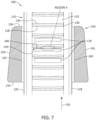
- the bottom surface is supported on the shoulders and the strap medial portion 132 overlays the biasing member 164, enabling the strap and body engagement members to effectively move into engagement as the strap moves in direction 101. See FIG. 7 .
- the strap 110 is advanced in the direction of insertion 101 until an object surrounded by the strap 110 is cinched to a desired torque or holding force, or until the strap 110 can no longer be advanced in the direction of insertion 101. Subsequently advancing the strap 110 in the second direction opposite the direction of insertion 101 causes the holding surface 128 of the strap 110 to engage the holding surface 172 of the body 150, preventing the strap 110 from further advancing in the opposite direction, and non-removably locking the strap 110 to the body 150 and defining a locked state where loosening displacement of the strap 110 is impeded.
- the biasing member 164 is adapted to apply a biasing force against the strap 110 upon insertion of the strap 110 into the insertion chamber 152, such that the inner wall 166 is biased against the strap 110.
- the leading surface 130 of the strap 110 first traverses the leading surface 174 of the body 150 and the holding surface 128 of the strap 110 interlocks with the holding surface 172 of the body 150.
- the holding surface 128 of the strap 110 engages the holding surface 172 of the body 150 upon advancement of the strap 110 in a direction opposite the direction of insertion 101 after at least one holding surface 128 of the strap 110 traverses over the holding surface 172 of the body 150 in the direction of insertion 101.
- the biasing member 164 contacts the strap urging the strap toward surface 160 and maintaining body engagement members 170 proximate the strap engagement members 126, thereby impeding loosening displacement of strap 110 in a direction opposite insertion direction 101.
- the body 150 includes a plurality of strap engagement members 170 which form the ratcheting mechanism, however it is understood that a single engagement member 170 may form the ratcheting mechanism together with the plurality of strap engagement members 126 of the strap 110.
- FIG. 6 illustrates a side view of the strap 110 inserted within the insertion chamber 152 of the body 150
- FIG. 7 illustrates a cross-sectional view of the strap 110 inserted within the insertion chamber 152 of the body 150.
- the strap 110 is integral to the second end 116 and to the body 150 such that the strap 110 can be looped around the body 150 and inserted from the insertion end 154 in the direction of insertion 101.
- the biasing member 164 applies a biasing force against the strap 110 such that the at least one body engagement member 170 of the body 150 engages with the plurality of strap engagement members 126 of the strap 110. The engagement is also shown in FIG. 7 .
- the non-linear surface profile 140 of the holding surface 128 of the strap 110 is convex relative to the second end 116 and to the body 150, and the non-linear surface profile 180 is concave relative to the direction of insertion 101 (or relative to the insertion end 154 of the body 150).
- the convex non-linear surface profile 140 of the strap 110 is oriented towards the insertion end 154 of the body 150. This configuration causes the convex non-linear contact surface profile 140 of the strap 110 to abut against and engage the concave non-linear holding surface profile 180 of the body 150 upon advancement of the strap 110 in a direction opposite the direction of insertion 101.
- the term "abut" with respect to engaged surface profiles denotes direct contact with a portion of the surface profiles.
- FIGS. 8 and 9 illustrate an object bundling apparatus 200 in accordance with an alternate embodiment of the present disclosure.
- FIG. 8 is a perspective view of the object bundling apparatus 200
- FIG. 9 is a cross-sectional view of a body 250 of the object bundling apparatus 200.
- the object bundling apparatus 200 of FIGS. 8 and 9 operates substantially the same as the object bundling apparatus 100 of FIGS. 1-7 .
- the object bundling apparatus 200 includes a strap 210 and a plurality of strap engagement members 226 similar to the strap 110 of FIGS. 1-7
- the body 250 includes at least one body engagement member 270 similar to the body 150 of FIGS. 1-7 .
- the plurality of strap engagement members 226 of the strap 210 are disposed on a bottom surface 225 of the strap 210.
- the plurality of strap engagement members 126 of the strap 210 include a holding surface 228 and a leading surface 230.
- the holding surface 228 is substantially perpendicular relative to the bottom surface 225 of the strap 210 and the leading surface 230 is oriented at an angle relative to the bottom surface 225 of the strap 210.
- the holding surface 228 of the strap 110 has a non-linear surface profile 240 defined between the edges 218, 220 of the strap 210.
- the non-linear surface profile 240 is arc-shaped.
- the non-linear surface profile 240 is concave relative to the second end 216 of the strap 210 and to the body 250.
- the at least one body engagement member 270 of the object bundling apparatus 200 has the same non-linear surface profile 280 and the same orientation as the at least one body engagement member 170 of the object bundling apparatus 100.
- the at least one body engagement member 270 of the object bundling apparatus 200 includes a holding surface 272 in the direction of the removal end 256 of the body 250, and a non-linear surface profile 280 of the at least one body engagement member 270 is concave relative to the direction of insertion 101.
- the concave non-linear surface profile 240 of the strap 210 is oriented towards the opening 265 of insertion end 254.
- This configuration causes the concave non-linear contact surface profile 240 of the strap 210 to nest with and engage the concave non-linear holding surface profile 280 of the body 250 upon advancement of the strap 210 in a direction opposite the direction of insertion 101.
- the term "nest" with respect to engaged surface profiles denotes direct complementary contact of the surface profiles, where each of the surface profiles substantially engage one another. The nesting of the surfaces causes the holding forces to be evenly distributed across the holding surfaces. The even distribution of holding forces reduces stresses across the holding surfaces, thereby reducing or preventing plastic deformation of the holding surfaces.
- the holding surfaces (172, 272) of the bodies (150, 250) of the cable bundling apparatuses (100, 200) have a concave non-linear holding surface profile (180, 280), and a holding surface (128, 228) of the straps (110, 210) have either a concave or convex non-linear holding surface profile (140, 240).
- the holding surfaces (172, 272) of the bodies (150, 250) may be concave or convex, such that the complimentary concave or convex non-linear holding surface profile (140, 240) of the straps (110, 210) either abut or nest with the non-linear holding surface profile (180, 280) of the bodies (150, 250).
- FIGS. 10 and 11 illustrate embodiments of an object bundling apparatus having angled lateral portions defining alternate non-linear surface profiles.
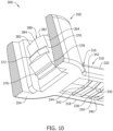
- FIG. 10 illustrates an object bundling apparatus 300 having chevron-shaped non-linear surface profiles
- FIG. 11 illustrates an object bundling apparatus 400 having non-linear surface profiles defined by a flat medial portion and angled lateral portions.
- a strap 310 includes a plurality of strap engagement members 326 having a holding surface 328 and a leading surface 330 similar to the plurality of strap engagement members (126, 226) of the object bundling apparatuses (100, 200) shown in FIGS 1-9 .
- a body 350 includes at least one body engagement member 370 having a holding surface 372 and a leading surface 374 similar to the at least one body engagement member (170, 270) of the object bundling apparatuses (100, 200) shown in FIGS 1-9 .
- a non-linear surface profile 340 of the plurality of strap engagement members 326 of the strap 310 has a chevron-shaped surface profile extending between the first end 318 and second end 320 of the strap 310.
- the chevron-shaped non-linear surface profile 340 is defined by angled lateral portions 342 extending between the edges 318, 320 of the strap 310.
- the angled lateral portions 342 meet at a medial point 344, and the medial point 344 may be oriented towards a first free end (not shown) of the strap 110 or towards a second end 316 of the strap 310 and to the body 350.
- the orientation of the medial point 344 is dependent on the orientation of the at least one body engagement member 370 of the body 350 such that the non-linear surface profile 340 of the strap 310 either abuts or nests with the at least one body engagement member 370 of the body 350 similar to the abutting or nesting configurations of the object bundling apparatuses (100, 200) shown in FIGS 1-9 .
- a non-linear surface profile 380 of the at least one body engagement member 370 of the body 350 has a chevron-shaped surface profile extending between a first lateral biasing member side 376 and a second lateral biasing member side 378 of a biasing member 364 of the body 350.
- the chevron-shaped non-linear surface profile 380 is defined by angled lateral portions 382 extending between the lateral biasing member sides 376, 378 of the body 350.
- the angled lateral portions 382 meet at a medial point 384, and the medial point 384 may be oriented towards an insertion end 354 of the body 350 or towards a removal end 356 of the body 350.
- the orientation of the medial point 384 is dependent on the orientation of the plurality of strap engagement members 326 of the strap 310 such that the non-linear surface profile 340 of the strap 310 either abuts or nests with the at least one body engagement member 370 of the body 350 similar to the abutting or nesting configurations of the object bundling apparatuses (100, 200) shown in FIGS 1-9 .
- a strap 410 includes a plurality of strap engagement members 426 having a holding surface 428 and a leading surface 430 similar to the plurality of strap engagement members (126, 226) of the object bundling apparatuses (100, 200) shown in FIGS 1-9 .
- a body 450 includes at least one body engagement member 470 having a holding surface 472 and a leading surface 474 similar to the at least one body engagement member (170, 270) of the object bundling apparatuses (100, 200) shown in FIGS 1-9 .
- a non-linear surface profile 440 of the plurality of strap engagement members 426 of the strap 410 is defined by a flat medial portion 444 and angled lateral portions 442extending between the first edge 418 and second edge 420 of the strap 110.
- the flat medial portion 444 may be oriented towards a first free end (not shown) of the strap 410 or towards a second end 416 of the strap 410 and to the body 450.
- the orientation of the flat medial portion 444 is dependent on the orientation of the at least one body engagement member 470 of the body 450 such that the non-linear surface profile 440 of the strap 410 either abuts or nests with the at least one body engagement member 470 of the body 450 similar to the abutting or nesting configurations of the object bundling apparatuses (100, 200) shown in FIGS 1-9 .
- a non-linear surface profile 480 of the at least one body engagement member 470 of the body 450 is defined by a flat medial portion 484 and angled lateral portions 482 extending between the lateral biasing member sides 476, 478 of the body 450.
- the flat medial portion 484 may be oriented towards an insertion end 454 of the body 450 or towards a removal end 456 of the body 450.
- the orientation of the flat medial portion 484 is dependent on the orientation of the plurality of strap engagement members 426 of the strap 410 such that the non-linear surface profile 440 of the strap 410 either abuts or nests with the at least one body engagement member 470 of the body 450 similar to the abutting or nesting configurations of the object bundling apparatuses (100, 200) shown in FIGS 1-9 .
- the recitation of "at least one of A, B and C” should be interpreted as one or more of a group of elements consisting of A, B and C, and should not be interpreted as requiring at least one of each of the listed elements A, B and C, regardless of whether A, B and C are related as categories or otherwise.
- the recitation of "A, B and/or C" or "at least one of A, B or C” should be interpreted as including any singular entity from the listed elements, e.g., A, any subset from the listed elements, e.g., A and B, or the entire list of elements A, B and C.
Landscapes
- Engineering & Computer Science (AREA)
- Mechanical Engineering (AREA)
- General Engineering & Computer Science (AREA)
- Clamps And Clips (AREA)
- Basic Packing Technique (AREA)
Abstract
An object bundling apparatus includes an opening defining an engagement channel having an inner wall. At least one body engagement member is disposed on the inner wall having a holding surface laterally bound by a first end and a second end. The holding surface has a non-linear surface profile between the first end and second end. A strap is adapted to be passed through the opening in a direction of insertion, the strap having a plurality of strap engagement members. Each of the strap engagement members includes a contact surface laterally bound by a first strap end and a second strap end. The contact surface has a non-linear surface profile between the first strap end and second strap end. The non-linear contact surface profile of the strap is configured to nest within the non-linear holding surface profile and/or abut against the non-linear holding surface profile upon advancement of the strap in a direction opposite the direction of insertion.
Description
- The field of the disclosure relates generally to object bundling systems and, more particularly, to object bundling apparatus having a non-linear contact surface profile.
- Object bundling apparatus are used to collect or combine a plurality of cables that are strung in a ceiling, or other suitable suspension location in a building or factory for example. The bundling or locking system may comprise a strap that is adapted to be wrapped around the cable bundle. The strap has a flexible, unitary body with an opening located along the strap.
- In use, the strap is wrapped around the cables and one end of the strap is inserted through the opening, and pulled through the opening in a first direction until the strap is positioned snugly against the collected cables. The strap includes outwardly directed locking members that impede loosening displacement of the strap end in a second direction, and as a result the locking members maintain the strap tightly against the cables.
- Known straps are flexible. As a result, over time the weight of the cables causes the locking to members to degrade or fail, resulting in strap loosening or a releasing of the previously secure bundled cables. Because the cable bundles are frequently maintained in ceilings or other difficult to access building locations, repairing object bundling apparatus can prove to be difficult. There is a need for an object bundling apparatus that maintains the support of the cable bundle over time.
- In a first aspect of the present disclosure, an object bundling apparatus is disclosed. The apparatus includes a body having an opening extending through the body, the opening defining an engagement channel having an inner wall. At least one body engagement member is disposed on the inner wall, the at least one body engagement member having a holding surface laterally bound by a first end and a second end. The holding surface has a non-linear surface profile between the first end and second end. A strap is adapted to be passed through the opening in a direction of insertion. The strap has a plurality of strap engagement members, each of the strap engagement members having a contact surface laterally bound by a first strap end and a second strap end. The contact surface has a non-linear surface profile between the first strap end and second strap end. The non-linear contact surface profile of the strap is configured to nest within the non-linear holding surface profile of the body upon advancement of the strap in a direction opposite the direction of insertion.
- In a second aspect of the present disclosure, an object bundling apparatus is disclosed. The apparatus includes a body having an opening extending through the body, the opening defining an engagement channel having an inner wall. At least one body engagement member is disposed on the inner wall, the at least one body engagement member having a holding surface laterally bound by a first end and a second end. The holding surface has a non-linear surface profile between the first end and second end. A strap is adapted to be passed through the opening in a direction of insertion. The strap has a plurality of strap engagement members, each of the strap engagement members having a contact surface laterally bound by a first strap end and a second strap end. The contact surface has a non-linear surface profile between the first strap end and second strap end. The non-linear contact surface profile of the strap is configured to abut against the non-linear holding surface profile of the body upon advancement of the strap in a direction opposite the direction of insertion.
-
-
FIG. 1 illustrates a perspective top view of an object bundling apparatus in accordance with one or more embodiments of the present disclosure; -
FIG. 2 illustrates a bottom view of the object bundling apparatus ofFIG. 1 ; -
FIG. 3 illustrates a bottom perspective view of the object bundling apparatus ofFIG. 1 ; -
FIG. 4 illustrates a cross-sectional view of a body of the object bundling apparatus ofFIG. 1 , taken along line 3-3' ofFig. 2 ; -
FIG. 5 illustrates a cross-sectional view of the body of the object bundling apparatus ofFIG. 1 , taken along line 5-5' ofFig. 1 ; -
FIG. 6 illustrates a cross-sectional view of a strap inserted into the body of the object bundling apparatus ofFIG. 1 ; -
FIG. 7 illustrates a cross-sectional view of a strap inserted into the body of the object bundling apparatus ofFIG. 1 ; -
FIG. 8 illustrates a bottom perspective view of an object bundling apparatus in accordance with a second embodiment of the present disclosure; -
FIG. 9 illustrates a cross-sectional view of a strap inserted into the body of the object bundling apparatus ofFIG. 8 ; -
FIG. 10 illustrates a cross-sectional view of an object bundling apparatus in accordance with a third embodiment of the present disclosure; and, -
FIG. 11 illustrates a cross-sectional view of an object bundling apparatus in accordance with a fourth embodiment of the present disclosure. - The reference symbols used in the drawings, and their meanings, are listed in summary form in the list of reference symbols. In principle, identical parts are provided with the same reference symbols in the figures.
- In the following specification and the claims, reference will be made to a number of terms, which shall be defined to have the following meanings.
- As used herein, the singular forms "a," "an," and "the" include plural references unless the context clearly dictates otherwise. The terms "comprising," "including," and "having" are intended to be inclusive and mean that there may be additional elements other than the listed elements. The terms "optional" or "optionally" means that the subsequently described event or circumstance may or may not occur, and that the description includes instances where the event occurs and instances where it does not.
- As used herein, the spatial terms "upper," "lower," "top" and "bottom" as used in the present disclosure shall denote a component, or an element of a component, which is upstream or downstream relative to other components and elements of components unless the context clearly dictates otherwise. The term "upper" or "top" shall denote a downstream component or element of a component, and the term "lower" or "bottom" shall denote an upstream component or element of a component. Where a component has a top surface and a bottom surface, the top surface is parallel to the bottom surface. Such relative spatial terms are used only to facilitate description and are not meant to be limiting.
- The present disclosure is directed to embodiments of an object bundling apparatus. The apparatus includes a body having an opening extending through the body, the opening defining an engagement channel having an inner wall. At least one body engagement member is disposed on the inner wall, the at least one body engagement member having a holding surface laterally bound by a first end and a second end. The holding surface has a non-linear surface profile between the first end and second end. A strap is adapted to be passed through the opening in a direction of insertion. The strap has a plurality of strap engagement members, each of the strap engagement members having a surface laterally bound by a first strap end and a second strap end. The surface has a non-linear surface profile between the first strap end and second strap end.
- In some embodiments, the non-linear surface profile of the strap is configured to nest within the non-linear holding surface profile of the body upon advancement of the strap in a direction opposite the direction of insertion. In some embodiments, the non-linear surface profile of the strap is configured to abut against the non-linear holding surface profile of the body upon advancement of the strap in a direction opposite the direction of insertion.
- As used herein, the term "non-linear surface profile," "non-linear edge," "non-linear surface" and "non-linear" generally refer to a holding surface and/or a leading surface having an edge which is not perpendicular to a length of the head or strap. The non-linear surface profile may be at an acute angle relative to the length of the head or strap. The non-linear surface profile may be curved or may include one or more angled linear segments. The non-linear surface profile may include a combination of curved and one or more linear segments.
- The
object bundling apparatus 100 of a first embodiment of the disclosure is shown inFIGS. 1-6 .FIG. 1 illustrates a top perspective view of anobject bundling apparatus 100 having astrap 110 and abody 150.FIG. 2 illustrates a bottom view of theobject bundling apparatus 100 andFIG. 3 illustrates a perspective cross-sectional view of theobject bundling apparatus 100 taken along line 3-3' as shown inFIG. 2 .FIG. 4 illustrates a perspective cross-sectional view of thebody 150 taken along line 3-3' as shown inFIG. 2 , andFIG. 5 illustrates a cross-sectional view of thebody 150 taken along line 5-5' as shown inFIG. 1 .FIG. 6 illustrates a cross-sectional view of thestrap 110 inserted into aninsertion chamber 152 of thebody 150 of theobject bundling apparatus 100. As shown inFIG. 1 he strap 110 is elongate and theelongate strap 110 includes a firstfree end 114, asecond end 116 made integral with thebody 150, and a firstlateral edge 118 and a secondlateral edge 120 where theedges ends strap 110 is made integral with thebody 150 at thesecond end 116 of thestrap 110, thereby forming a unitary body comprising thestrap 110 andbody 150. In some embodiments, thestrap 110 andbody 150 are discrete members. In some embodiments, thestrap 110 and thebody 150 are comprised of a material selected from a group consisting of polymer, nylon, polyamide, heat stabilized nylon, and UV stabilized nylon. - In the illustrated embodiments, a
bottom surface 125 of thestrap 110 includes amedial portion 132 laterally bound by theedges strap 110. Themedial portion 132 includes a plurality ofstrap engagement members 126. As shown inFIGS. 3 and5 , themedial portion 132 is recessed relative to thebottom surface 125.. As explained in further detail below with reference toFIGS. 6 and7 , the plurality ofstrap engagement members 126 of thestrap 110 are configured to interlock with at least onebody engagement member 170 of thebody 150 as the firstfree end 114 of thestrap 110 is advanced through theinsertion chamber 152 of thebody 150 in a direction of insertion (indicated byarrows 101 in the figures). In some embodiments, the plurality ofstrap engagement members 126 of thestrap 110 are barbed teeth that each interlocking or engaging with at least onebody engagement member 170 of thebody 150. In some embodiments, the engagement members are configured as a ratcheting mechanism, where the plurality ofstrap engagement members 126 of thestrap 110 are advanceable in the direction ofinsertion 101, but are prevented from advancing in the opposite direction by the engagement between the strap engagement members andbody engagement members 170. - As best shown in
FIG. 5 , in some embodiments, the plurality ofstrap engagement members 126 of thestrap 110 include a holdingsurface 128 and aleading surface 130. In some embodiments, the holdingsurface 128 is substantially perpendicular relative to thebottom surface 125 of thestrap 110 and the leadingsurface 130 is oriented at an angle relative to the substantially planarbottom surface 125 of thestrap 110. In some embodiments, the leadingsurface 130 is directed towards and facing of the firstfree end 114 of thestrap 110 and the holdingsurface 128 is in the direction of thesecond end 116. - As best shown in
FIG. 2 , the holdingsurface 128 of thestrap 110 has anon-linear surface profile 140 defined between theedges strap 110. In the illustrated embodiments ofFIGS. 1-7 , thenon-linear surface profile 140 is arc-shaped, however in some embodiments, the non-linear surface profile may have any shape. Furthermore, as best shown inFIG. 2 , thenon-linear surface profile 140 is convex relative to thesecond end 116 of the strap, and to thebody 150. In some embodiments, thenon-linear surface profile 140 may be concave relative to thesecond end 116 and to thebody 150 as will be explained in further detail below. In some embodiments, the leadingsurface 130 also has an arc-shaped non-linear surface profile. In some embodiments, the leadingsurface 130 is concave or convex. - With reference to
FIGS. 1 through 5 , thebody 150 includes aninsertion end 154 and aremoval end 156 opposite theinsertion end 154. In some embodiments, theremoval end 156 of thebody 150 andtop surface 124 of thestrap 110 define top surfaces of theobject bundling apparatus 100. In some embodiments, theleading end 154 of thebody 150 and thebottom surface 125 of thestrap 110 are planar. The body also includes afirst channel wall 160, asecond channel wall 162 andlateral sides first channel wall 160,second channel wall 162 andlateral sides insertion chamber 152 adapted to receive thestrap 110. Theinsertion chamber 152 extends through thebody 150 from theinsertion end 154 to theremoval end 156, and thestrap 110 is adapted to be advanced through theinsertion chamber 152 from theinsertion end 154 of thebody 150 in the direction ofinsertion 101. The strap enters the insertion chamber through opening 163 formed on theinsertion end 154 and exits the insertion chamber through opening 165 formed on theremoval end 156. - As best shown in
Fig. 5 , In some embodiments, thesecond channel wall 162 includes a biasingmember 164 extending from thesecond channel wall 162 into theinsertion chamber 152. The biasingmember 164 is integral to thesecond channel wall 162 adjacent theinsertion end 154 and extends into theinsertion chamber 152 towards theremoval end 156 and terminates at a free end. In the illustrated embodiments, the biasingmember 164 is a cantilevered member having one end bound by and integral to thesecond channel wall 162. As will be explained in further detail below, the biasingmember 164 is adapted to apply a biasing force against thestrap 110 upon insertion of thestrap 110 into theinsertion chamber 152, such that the biasing member is urged towards the strap member and thereby maintains engagement between thebody engagement members 170 and thestrap engagement members 126. - With reference to
FIGS. 1 through 5 , thebody 150 further includes at least onebody engagement member 170 disposed on the biasingmember 164 and directed towards theinsertion chamber 152. In some embodiments, the least onebody engagement member 170 of thebody 150 are barbed teeth that each interlock with the plurality ofstrap engagement members 126 of thestrap 110. As best shown inFIGS. 4 and5 , in some embodiments, the at least onebody engagement member 170 includes a holdingsurface 172 and aleading surface 174. The holdingsurface 172 is laterally bound by a first lateral biasingmember side 176 and a second lateral biasingmember side 178. In some embodiments, the holdingsurface 172 is substantially parallel to the opening 163 on theinsertion end 154. The leadingsurface 174 is oriented at an angle of less than ninety degrees relative to the respective holding surfaces. The leadingsurface 174 extends between adjacent holding surfaces in the direction ofinsertion 101. - As best shown in
FIG. 4 , the holdingsurface 172 has a non-linear surface profile orcontour 180 defined between thefirst end 176 andsecond end 178. In the illustrated embodiments ofFIGS. 1-7 , thenon-linear surface profile 180 is arc-shaped, however it is understood that the non-linear surface profile may have any shape. Furthermore, in the illustrated embodiments ofFIGS. 1-7 , thenon-linear surface profile 180 is concave relative to the direction of insertion 101 (as best shown inFIGS. 4 and7 ). In some embodiments, thenon-linear surface profile 180 may be convex relative to the direction ofinsertion 101. In some embodiments, the leadingsurface 174 also has an arc-shaped non-linear surface profile. In some embodiments, the leadingsurface 174 is concave or convex. The body includesinterior shoulder members insertion chamber 152. The shoulder members extend between theinsertion end 154 and theremoval end 156 and are adjacent the first lateral biasingmember side 176 and second lateral biasingmember side 178. When the strap is inserted in the insertion chamber, the bottom surface is supported on the shoulders and the strapmedial portion 132 overlays the biasingmember 164, enabling the strap and body engagement members to effectively move into engagement as the strap moves indirection 101. SeeFIG. 7 . - In operation, the
strap 110 is advanced in the direction ofinsertion 101 until an object surrounded by thestrap 110 is cinched to a desired torque or holding force, or until thestrap 110 can no longer be advanced in the direction ofinsertion 101. Subsequently advancing thestrap 110 in the second direction opposite the direction ofinsertion 101 causes the holdingsurface 128 of thestrap 110 to engage the holdingsurface 172 of thebody 150, preventing thestrap 110 from further advancing in the opposite direction, and non-removably locking thestrap 110 to thebody 150 and defining a locked state where loosening displacement of thestrap 110 is impeded. The biasingmember 164 is adapted to apply a biasing force against thestrap 110 upon insertion of thestrap 110 into theinsertion chamber 152, such that theinner wall 166 is biased against thestrap 110. - As the first
free end 114 of thestrap 110 is inserted into thebody 150, the leadingsurface 130 of thestrap 110 first traverses the leadingsurface 174 of thebody 150 and the holdingsurface 128 of thestrap 110 interlocks with the holdingsurface 172 of thebody 150. As best shown inFIG. 7 , The holdingsurface 128 of thestrap 110 engages the holdingsurface 172 of thebody 150 upon advancement of thestrap 110 in a direction opposite the direction ofinsertion 101 after at least one holdingsurface 128 of thestrap 110 traverses over the holdingsurface 172 of thebody 150 in the direction ofinsertion 101. The biasingmember 164, contacts the strap urging the strap towardsurface 160 and maintainingbody engagement members 170 proximate thestrap engagement members 126, thereby impeding loosening displacement ofstrap 110 in a direction oppositeinsertion direction 101. In the illustrated embodiment, thebody 150 includes a plurality ofstrap engagement members 170 which form the ratcheting mechanism, however it is understood that asingle engagement member 170 may form the ratcheting mechanism together with the plurality ofstrap engagement members 126 of thestrap 110. -
FIG. 6 illustrates a side view of thestrap 110 inserted within theinsertion chamber 152 of thebody 150 andFIG. 7 illustrates a cross-sectional view of thestrap 110 inserted within theinsertion chamber 152 of thebody 150. As shown, thestrap 110 is integral to thesecond end 116 and to thebody 150 such that thestrap 110 can be looped around thebody 150 and inserted from theinsertion end 154 in the direction ofinsertion 101. The biasingmember 164 applies a biasing force against thestrap 110 such that the at least onebody engagement member 170 of thebody 150 engages with the plurality ofstrap engagement members 126 of the strap 110.The engagement is also shown inFIG. 7 . - As previously set forth, the
non-linear surface profile 140 of the holdingsurface 128 of thestrap 110 is convex relative to thesecond end 116 and to thebody 150, and thenon-linear surface profile 180 is concave relative to the direction of insertion 101 (or relative to theinsertion end 154 of the body 150). With thestrap 110 looped though thebody 150 from theinsertion end 154, the convexnon-linear surface profile 140 of thestrap 110 is oriented towards theinsertion end 154 of thebody 150. This configuration causes the convex non-linearcontact surface profile 140 of thestrap 110 to abut against and engage the concave non-linear holdingsurface profile 180 of thebody 150 upon advancement of thestrap 110 in a direction opposite the direction ofinsertion 101. Because of thenon-linear contours FIG. 7 . The concentration of holding forces at REGION A effectuate a stronger ratcheting lock which prevents strip-out of thestrap 110 from thebody 150. - As used herein, the term "abut" with respect to engaged surface profiles denotes direct contact with a portion of the surface profiles.
-
FIGS. 8 and9 illustrate anobject bundling apparatus 200 in accordance with an alternate embodiment of the present disclosure.FIG. 8 is a perspective view of theobject bundling apparatus 200 andFIG. 9 is a cross-sectional view of abody 250 of theobject bundling apparatus 200. Theobject bundling apparatus 200 ofFIGS. 8 and9 operates substantially the same as theobject bundling apparatus 100 ofFIGS. 1-7 . Theobject bundling apparatus 200 includes astrap 210 and a plurality ofstrap engagement members 226 similar to thestrap 110 ofFIGS. 1-7 , and thebody 250 includes at least onebody engagement member 270 similar to thebody 150 ofFIGS. 1-7 . - The plurality of
strap engagement members 226 of thestrap 210 are disposed on abottom surface 225 of thestrap 210. The plurality ofstrap engagement members 126 of thestrap 210 include a holdingsurface 228 and aleading surface 230. In some embodiments, the holdingsurface 228 is substantially perpendicular relative to thebottom surface 225 of thestrap 210 and the leadingsurface 230 is oriented at an angle relative to thebottom surface 225 of thestrap 210. The holdingsurface 228 of thestrap 110 has anon-linear surface profile 240 defined between theedges strap 210. In some embodiments, thenon-linear surface profile 240 is arc-shaped. In the illustrated embodiments, thenon-linear surface profile 240 is concave relative to thesecond end 216 of thestrap 210 and to thebody 250. - The at least one
body engagement member 270 of theobject bundling apparatus 200 has the samenon-linear surface profile 280 and the same orientation as the at least onebody engagement member 170 of theobject bundling apparatus 100. In particular, the at least onebody engagement member 270 of theobject bundling apparatus 200 includes a holdingsurface 272 in the direction of theremoval end 256 of thebody 250, and anon-linear surface profile 280 of the at least onebody engagement member 270 is concave relative to the direction ofinsertion 101. - As shown in
FIG. 9 , with thestrap 210 looped though thebody 250 from theinsertion end 254 , the concavenon-linear surface profile 240 of thestrap 210 is oriented towards the opening 265 ofinsertion end 254. This configuration causes the concave non-linearcontact surface profile 240 of thestrap 210 to nest with and engage the concave non-linear holdingsurface profile 280 of thebody 250 upon advancement of thestrap 210 in a direction opposite the direction ofinsertion 101. As used herein, the term "nest" with respect to engaged surface profiles denotes direct complementary contact of the surface profiles, where each of the surface profiles substantially engage one another. The nesting of the surfaces causes the holding forces to be evenly distributed across the holding surfaces. The even distribution of holding forces reduces stresses across the holding surfaces, thereby reducing or preventing plastic deformation of the holding surfaces. - In the illustrated embodiments, the holding surfaces (172, 272) of the bodies (150, 250) of the cable bundling apparatuses (100, 200) have a concave non-linear holding surface profile (180, 280), and a holding surface (128, 228) of the straps (110, 210) have either a concave or convex non-linear holding surface profile (140, 240). In some embodiments, the holding surfaces (172, 272) of the bodies (150, 250) may be concave or convex, such that the complimentary concave or convex non-linear holding surface profile (140, 240) of the straps (110, 210) either abut or nest with the non-linear holding surface profile (180, 280) of the bodies (150, 250).
-
FIGS. 10 and11 illustrate embodiments of an object bundling apparatus having angled lateral portions defining alternate non-linear surface profiles.FIG. 10 illustrates anobject bundling apparatus 300 having chevron-shaped non-linear surface profiles andFIG. 11 illustrates anobject bundling apparatus 400 having non-linear surface profiles defined by a flat medial portion and angled lateral portions. - Turning first to the obj
ect bundling apparatus 300 shown inFIG. 10 , astrap 310 includes a plurality ofstrap engagement members 326 having a holdingsurface 328 and aleading surface 330 similar to the plurality of strap engagement members (126, 226) of the object bundling apparatuses (100, 200) shown inFIGS 1-9 . Likewise, abody 350 includes at least onebody engagement member 370 having a holdingsurface 372 and a leading surface 374 similar to the at least one body engagement member (170, 270) of the object bundling apparatuses (100, 200) shown inFIGS 1-9 . - A
non-linear surface profile 340 of the plurality ofstrap engagement members 326 of thestrap 310 has a chevron-shaped surface profile extending between thefirst end 318 andsecond end 320 of thestrap 310. The chevron-shapednon-linear surface profile 340 is defined by angledlateral portions 342 extending between theedges strap 310. In some embodiments, the angledlateral portions 342 meet at amedial point 344, and themedial point 344 may be oriented towards a first free end (not shown) of thestrap 110 or towards asecond end 316 of thestrap 310 and to thebody 350. The orientation of themedial point 344 is dependent on the orientation of the at least onebody engagement member 370 of thebody 350 such that thenon-linear surface profile 340 of thestrap 310 either abuts or nests with the at least onebody engagement member 370 of thebody 350 similar to the abutting or nesting configurations of the object bundling apparatuses (100, 200) shown inFIGS 1-9 . - A
non-linear surface profile 380 of the at least onebody engagement member 370 of thebody 350 has a chevron-shaped surface profile extending between a first lateral biasingmember side 376 and a second lateral biasingmember side 378 of a biasingmember 364 of thebody 350. The chevron-shapednon-linear surface profile 380 is defined by angledlateral portions 382 extending between the lateral biasingmember sides body 350. In some embodiments, the angledlateral portions 382 meet at amedial point 384, and themedial point 384 may be oriented towards aninsertion end 354 of thebody 350 or towards a removal end 356 of thebody 350. The orientation of themedial point 384 is dependent on the orientation of the plurality ofstrap engagement members 326 of thestrap 310 such that thenon-linear surface profile 340 of thestrap 310 either abuts or nests with the at least onebody engagement member 370 of thebody 350 similar to the abutting or nesting configurations of the object bundling apparatuses (100, 200) shown inFIGS 1-9 . - Turning next to the obj
ect bundling apparatus 400 shown inFIG. 11 , a strap 410 includes a plurality ofstrap engagement members 426 having a holdingsurface 428 and aleading surface 430 similar to the plurality of strap engagement members (126, 226) of the object bundling apparatuses (100, 200) shown inFIGS 1-9 . Likewise, abody 450 includes at least onebody engagement member 470 having a holdingsurface 472 and a leading surface 474 similar to the at least one body engagement member (170, 270) of the object bundling apparatuses (100, 200) shown inFIGS 1-9 . - A
non-linear surface profile 440 of the plurality ofstrap engagement members 426 of the strap 410 is defined by a flatmedial portion 444 and angled lateral portions 442extending between thefirst edge 418 andsecond edge 420 of thestrap 110. In some embodiments, the flatmedial portion 444 may be oriented towards a first free end (not shown) of the strap 410 or towards asecond end 416 of the strap 410 and to thebody 450. The orientation of the flatmedial portion 444 is dependent on the orientation of the at least onebody engagement member 470 of thebody 450 such that thenon-linear surface profile 440 of the strap 410 either abuts or nests with the at least onebody engagement member 470 of thebody 450 similar to the abutting or nesting configurations of the object bundling apparatuses (100, 200) shown inFIGS 1-9 . - A
non-linear surface profile 480 of the at least onebody engagement member 470 of thebody 450 is defined by a flatmedial portion 484 and angledlateral portions 482 extending between the lateral biasingmember sides body 450. In some embodiments, the flatmedial portion 484 may be oriented towards aninsertion end 454 of thebody 450 or towards a removal end 456 of thebody 450. The orientation of the flatmedial portion 484 is dependent on the orientation of the plurality ofstrap engagement members 426 of the strap 410 such that thenon-linear surface profile 440 of the strap 410 either abuts or nests with the at least onebody engagement member 470 of thebody 450 similar to the abutting or nesting configurations of the object bundling apparatuses (100, 200) shown inFIGS 1-9 . - Other variations to the disclosed embodiments can be understood and effected by those skilled in the art in practicing the claimed invention, from the study of the drawings, the disclosure, and the appended claims. In the claims the word "comprising" does not exclude other elements or steps and the indefinite article "a" or "an" does not exclude a plurality. The mere fact that certain measures are recited in mutually different dependent claims does not indicate that a combination of these measures cannot be used to advantage. Any reference signs in the claims should not be construed as limiting the scope of the claims.
- While the invention has been illustrated and described in detail in the drawings and foregoing description, such illustration and description are to be considered illustrative or exemplary and not restrictive. It will be understood that changes and modifications may be made by those of ordinary skill within the scope of the following claims. In particular, the present invention covers further embodiments with any combination of features from different embodiments described above and below. Additionally, statements made herein characterizing the invention refer to an embodiment of the invention and not necessarily all embodiments.
- The terms used in the claims should be construed to have the broadest reasonable interpretation consistent with the foregoing description. For example, the use of the article "a" or "the" in introducing an element should not be interpreted as being exclusive of a plurality of elements. Likewise, the recitation of "or" should be interpreted as being inclusive, such that the recitation of "A or B" is not exclusive of "A and B," unless it is clear from the context or the foregoing description that only one of A and B is intended. Further, the recitation of "at least one of A, B and C" should be interpreted as one or more of a group of elements consisting of A, B and C, and should not be interpreted as requiring at least one of each of the listed elements A, B and C, regardless of whether A, B and C are related as categories or otherwise. Moreover, the recitation of "A, B and/or C" or "at least one of A, B or C" should be interpreted as including any singular entity from the listed elements, e.g., A, any subset from the listed elements, e.g., A and B, or the entire list of elements A, B and C.
- This written description uses examples to disclose the invention, including the best mode, and also to enable any person skilled in the art to practice the invention, including making and using any devices or systems and performing any incorporated methods. The patentable scope of the invention is defined by the claims, and may include other examples that occur to those skilled in the art. Such other examples are intended to be within the scope of the claims if they have structural elements that do not differ from the literal language of the claims, or if they include equivalent structural elements with insubstantial differences from the literal languages of the claims.
Claims (12)
- An object bundling apparatus comprising:a body having an opening extending through the body, the opening defining an engagement channel having an inner wall;at least one body engagement member disposed on the inner wall, the at least one body engagement member comprising a holding surface laterally bound by a first end and a second end, the holding surface having a non-linear surface profile between the first end and second end; anda strap adapted to be passed through the opening in a direction of insertion, the strap having a plurality of strap engagement members, each of the strap engagement members comprising a contact surface laterally bound by a first strap end and a second strap end, the contact surface having a non-linear surface profile between the first strap end and the second strap end;wherein the non-linear contact surface profile of the strap is configured to nest within and/or abut against the non-linear holding surface profile of the body upon advancement of the strap in a direction opposite the direction of insertion.
- The object bundling apparatus of claim 1, wherein the holding surface of the at least one body engagement member has an arc-shaped surface profile.
- The object bundling apparatus of claim 1 or 2, wherein the holding surface of the at least one body engagement member has a concave surface profile relative to the direction of insertion.
- The object bundling apparatus of claim 1 or 2, wherein the holding surface of the at least one body engagement member has a convex surface profile relative to the direction of insertion.
- The object bundling apparatus of any one of the preceding claims, wherein the contact surface of the plurality of strap engagement members has a concave arc-shaped surface profile relative to the direction of insertion.
- The object bundling apparatus of any one of claims 1 to 4, wherein the contact surface of the plurality of strap engagement members has a convex arc-shaped surface profile relative to the direction of insertion.
- The object bundling apparatus of claim 1, wherein the holding surface of the at least one body engagement member has a chevron-shaped surface profile extending between the first end and the second end.
- The object bundling apparatus of claim 7, wherein the chevron-shaped surface profile is defined by angled lateral portions extending between the first end and second end.
- The object bundling apparatus of claim 7 or 8, wherein the contact surface of the plurality of strap engagement members has a chevron-shaped surface profile extending between the first strap end and the second strap end.
- The object bundling apparatus of any one of claims 7 to 9, wherein the chevron-shaped surface profile is defined by angled lateral portions extending between the first strap end and the second strap end.
- The object bundling apparatus of claim 1, wherein the holding surface of the at least one body engagement member has a surface profile defined by a flat medial portion and angled lateral portions extending from the flat medial portion to the first end and second end.
- The object bundling apparatus of claim 11, wherein the contact surface of the plurality of strap engagement members has a surface profile defined by a flat medial portion and angled lateral portions extending from the flat medial portion to the first strap end and second strap end.
Applications Claiming Priority (1)
| Application Number | Priority Date | Filing Date | Title |
|---|---|---|---|
| US18/332,386 US20240410498A1 (en) | 2023-06-09 | 2023-06-09 | Object bundling apparatus |
Publications (1)
| Publication Number | Publication Date |
|---|---|
| EP4474308A1 true EP4474308A1 (en) | 2024-12-11 |
Family
ID=91432855
Family Applications (1)
| Application Number | Title | Priority Date | Filing Date |
|---|---|---|---|
| EP24180546.4A Pending EP4474308A1 (en) | 2023-06-09 | 2024-06-06 | Object bundling apparatus |
Country Status (5)
| Country | Link |
|---|---|
| US (1) | US20240410498A1 (en) |
| EP (1) | EP4474308A1 (en) |
| CN (1) | CN119100014A (en) |
| CA (1) | CA3240824A1 (en) |
| MX (1) | MX2024006229A (en) |
Citations (4)
| Publication number | Priority date | Publication date | Assignee | Title |
|---|---|---|---|---|
| BE518012A (en) * | 1952-03-01 | 1953-03-14 | Colombo R | Belt buckle |
| US3735449A (en) * | 1972-02-28 | 1973-05-29 | Western Filament Inc | Chevron bundle tie |
| US3747164A (en) * | 1972-11-01 | 1973-07-24 | Thomas & Betts Corp | Releasable self-locking bundling strap |
| US10407226B2 (en) * | 2013-02-14 | 2019-09-10 | Rapstrap Limited | Tie strips |
Family Cites Families (16)
| Publication number | Priority date | Publication date | Assignee | Title |
|---|---|---|---|---|
| US3875620A (en) * | 1974-06-21 | 1975-04-08 | Robert E Wells | Tie |
| US3983603A (en) * | 1974-09-30 | 1976-10-05 | Dennison Manufacturing Company | Tie for bundling items |
| US3973610A (en) * | 1975-10-20 | 1976-08-10 | Gene Ballin | Tie strip |
| US3991444A (en) * | 1976-02-18 | 1976-11-16 | Panduit Corporation | Releasable cable tie |
| DE2717622A1 (en) * | 1977-04-21 | 1978-10-26 | Fastex Division Der Itw Ateco | ONE PIECE CABLE TAPE |
| US4754529A (en) * | 1980-07-14 | 1988-07-05 | Dennison Manufacturing Company | Bundling of objects |
| CA1214028A (en) * | 1981-09-30 | 1986-11-18 | Itw Limited | Security seals |
| US4510649A (en) * | 1983-06-03 | 1985-04-16 | Yudis Donald W | Tie strip |
| CA2027720A1 (en) * | 1990-10-16 | 1992-04-17 | Claude Mauffette | Belt |
| US5774953A (en) * | 1997-05-01 | 1998-07-07 | Mao; Chen Shou | Buckling device for baggage and the like |
| US6185792B1 (en) * | 1997-11-21 | 2001-02-13 | Thomas & Betts International, Inc. | Bi-directional self-locking cable tie |
| US7017237B2 (en) * | 2003-12-02 | 2006-03-28 | Thomas & Betts International, Inc. | High performance cable tie |
| US9879823B2 (en) * | 2014-12-31 | 2018-01-30 | Hand Held Products, Inc. | Reclosable strap assembly |
| WO2017100770A1 (en) * | 2015-12-10 | 2017-06-15 | Avery Dennison Retail Information Services, Llc | Fastener with support feature for pawl component |
| US10480688B2 (en) * | 2016-11-14 | 2019-11-19 | Abb Schweiz Ag | High strength single piece cable tie locking mechanism |
| US10259627B2 (en) * | 2017-05-11 | 2019-04-16 | Marking Services Incorporated | Fastening system |
-
2023
- 2023-06-09 US US18/332,386 patent/US20240410498A1/en active Pending
-
2024
- 2024-05-22 MX MX2024006229A patent/MX2024006229A/en unknown
- 2024-06-05 CN CN202410720302.XA patent/CN119100014A/en active Pending
- 2024-06-06 EP EP24180546.4A patent/EP4474308A1/en active Pending
- 2024-06-07 CA CA3240824A patent/CA3240824A1/en active Pending
Patent Citations (4)
| Publication number | Priority date | Publication date | Assignee | Title |
|---|---|---|---|---|
| BE518012A (en) * | 1952-03-01 | 1953-03-14 | Colombo R | Belt buckle |
| US3735449A (en) * | 1972-02-28 | 1973-05-29 | Western Filament Inc | Chevron bundle tie |
| US3747164A (en) * | 1972-11-01 | 1973-07-24 | Thomas & Betts Corp | Releasable self-locking bundling strap |
| US10407226B2 (en) * | 2013-02-14 | 2019-09-10 | Rapstrap Limited | Tie strips |
Also Published As
| Publication number | Publication date |
|---|---|
| CN119100014A (en) | 2024-12-10 |
| CA3240824A1 (en) | 2025-06-17 |
| MX2024006229A (en) | 2025-01-09 |
| US20240410498A1 (en) | 2024-12-12 |
Similar Documents
| Publication | Publication Date | Title |
|---|---|---|
| US11097878B2 (en) | Flexible connector | |
| CN100564181C (en) | High Performance Cable Ties | |
| CN106457677B (en) | Cable tie knotting device and method of use | |
| US7661632B2 (en) | Mounting device for studs comprising T-shaped channels | |
| US3971105A (en) | Mount for flat objects such as flat cables | |
| EP1369630A1 (en) | Cinch strap | |
| JPH04210108A (en) | Tie head | |
| US20190241334A1 (en) | Fastening system | |
| GB2507082A (en) | Cable Tie and Retention System | |
| JP2008068927A (en) | Breakage type bundling apparatus | |
| US12040603B2 (en) | Device for cable management | |
| US7681844B2 (en) | Tie for elongated objects such as cables, pipes or the like | |
| US12365524B2 (en) | Cable bundling system | |
| CN107205758A (en) | The fixing device of flat rubber belting is fixed on bone parts | |
| US20240360922A1 (en) | Cable Tie Cradle Mount Fixings | |
| EP4474308A1 (en) | Object bundling apparatus | |
| US20170088322A1 (en) | Cable tie | |
| US20160016709A1 (en) | In-line cable tie with flexible head | |
| EP2815990B1 (en) | Highly flexible cable tie | |
| US11745923B2 (en) | Cable or utility tie | |
| EP4474307A1 (en) | In-line cable bundling system | |
| JP6317441B2 (en) | Cable ties | |
| EP4542060A1 (en) | Twist-lock fixings | |
| WO2016203032A1 (en) | Retainer for cable raceway | |
| US9068672B2 (en) | T-style grommet attachment system and method |
Legal Events
| Date | Code | Title | Description |
|---|---|---|---|
| PUAI | Public reference made under article 153(3) epc to a published international application that has entered the european phase |
Free format text: ORIGINAL CODE: 0009012 |
|
| STAA | Information on the status of an ep patent application or granted ep patent |
Free format text: STATUS: REQUEST FOR EXAMINATION WAS MADE |
|
| 17P | Request for examination filed |
Effective date: 20240606 |
|
| AK | Designated contracting states |
Kind code of ref document: A1 Designated state(s): AL AT BE BG CH CY CZ DE DK EE ES FI FR GB GR HR HU IE IS IT LI LT LU LV MC ME MK MT NL NO PL PT RO RS SE SI SK SM TR |