EP4474297A1 - Package forming apparatus and packaging machine for forming packages - Google Patents
Package forming apparatus and packaging machine for forming packages Download PDFInfo
- Publication number
- EP4474297A1 EP4474297A1 EP24179162.3A EP24179162A EP4474297A1 EP 4474297 A1 EP4474297 A1 EP 4474297A1 EP 24179162 A EP24179162 A EP 24179162A EP 4474297 A1 EP4474297 A1 EP 4474297A1
- Authority
- EP
- European Patent Office
- Prior art keywords
- operative
- operative unit
- unit
- forming apparatus
- tube
- Prior art date
- Legal status (The legal status is an assumption and is not a legal conclusion. Google has not performed a legal analysis and makes no representation as to the accuracy of the status listed.)
- Pending
Links
Images



Classifications
-
- B—PERFORMING OPERATIONS; TRANSPORTING
- B65—CONVEYING; PACKING; STORING; HANDLING THIN OR FILAMENTARY MATERIAL
- B65B—MACHINES, APPARATUS OR DEVICES FOR, OR METHODS OF, PACKAGING ARTICLES OR MATERIALS; UNPACKING
- B65B51/00—Devices for, or methods of, sealing or securing package folds or closures; Devices for gathering or twisting wrappers, or necks of bags
- B65B51/10—Applying or generating heat or pressure or combinations thereof
- B65B51/26—Devices specially adapted for producing transverse or longitudinal seams in webs or tubes
- B65B51/30—Devices, e.g. jaws, for applying pressure and heat, e.g. for subdividing filled tubes
- B65B51/306—Counter-rotating devices
-
- B—PERFORMING OPERATIONS; TRANSPORTING
- B29—WORKING OF PLASTICS; WORKING OF SUBSTANCES IN A PLASTIC STATE IN GENERAL
- B29C—SHAPING OR JOINING OF PLASTICS; SHAPING OF MATERIAL IN A PLASTIC STATE, NOT OTHERWISE PROVIDED FOR; AFTER-TREATMENT OF THE SHAPED PRODUCTS, e.g. REPAIRING
- B29C65/00—Joining or sealing of preformed parts, e.g. welding of plastics materials; Apparatus therefor
- B29C65/02—Joining or sealing of preformed parts, e.g. welding of plastics materials; Apparatus therefor by heating, with or without pressure
-
- B—PERFORMING OPERATIONS; TRANSPORTING
- B29—WORKING OF PLASTICS; WORKING OF SUBSTANCES IN A PLASTIC STATE IN GENERAL
- B29C—SHAPING OR JOINING OF PLASTICS; SHAPING OF MATERIAL IN A PLASTIC STATE, NOT OTHERWISE PROVIDED FOR; AFTER-TREATMENT OF THE SHAPED PRODUCTS, e.g. REPAIRING
- B29C66/00—General aspects of processes or apparatus for joining preformed parts
- B29C66/70—General aspects of processes or apparatus for joining preformed parts characterised by the composition, physical properties or the structure of the material of the parts to be joined; Joining with non-plastics material
- B29C66/72—General aspects of processes or apparatus for joining preformed parts characterised by the composition, physical properties or the structure of the material of the parts to be joined; Joining with non-plastics material characterised by the structure of the material of the parts to be joined
- B29C66/723—General aspects of processes or apparatus for joining preformed parts characterised by the composition, physical properties or the structure of the material of the parts to be joined; Joining with non-plastics material characterised by the structure of the material of the parts to be joined being multi-layered
- B29C66/7232—General aspects of processes or apparatus for joining preformed parts characterised by the composition, physical properties or the structure of the material of the parts to be joined; Joining with non-plastics material characterised by the structure of the material of the parts to be joined being multi-layered comprising a non-plastics layer
- B29C66/72321—General aspects of processes or apparatus for joining preformed parts characterised by the composition, physical properties or the structure of the material of the parts to be joined; Joining with non-plastics material characterised by the structure of the material of the parts to be joined being multi-layered comprising a non-plastics layer consisting of metals or their alloys
-
- B—PERFORMING OPERATIONS; TRANSPORTING
- B29—WORKING OF PLASTICS; WORKING OF SUBSTANCES IN A PLASTIC STATE IN GENERAL
- B29C—SHAPING OR JOINING OF PLASTICS; SHAPING OF MATERIAL IN A PLASTIC STATE, NOT OTHERWISE PROVIDED FOR; AFTER-TREATMENT OF THE SHAPED PRODUCTS, e.g. REPAIRING
- B29C66/00—General aspects of processes or apparatus for joining preformed parts
- B29C66/70—General aspects of processes or apparatus for joining preformed parts characterised by the composition, physical properties or the structure of the material of the parts to be joined; Joining with non-plastics material
- B29C66/72—General aspects of processes or apparatus for joining preformed parts characterised by the composition, physical properties or the structure of the material of the parts to be joined; Joining with non-plastics material characterised by the structure of the material of the parts to be joined
- B29C66/723—General aspects of processes or apparatus for joining preformed parts characterised by the composition, physical properties or the structure of the material of the parts to be joined; Joining with non-plastics material characterised by the structure of the material of the parts to be joined being multi-layered
- B29C66/7232—General aspects of processes or apparatus for joining preformed parts characterised by the composition, physical properties or the structure of the material of the parts to be joined; Joining with non-plastics material characterised by the structure of the material of the parts to be joined being multi-layered comprising a non-plastics layer
- B29C66/72327—General aspects of processes or apparatus for joining preformed parts characterised by the composition, physical properties or the structure of the material of the parts to be joined; Joining with non-plastics material characterised by the structure of the material of the parts to be joined being multi-layered comprising a non-plastics layer consisting of natural products or their composites, not provided for in B29C66/72321 - B29C66/72324
- B29C66/72328—Paper
-
- B—PERFORMING OPERATIONS; TRANSPORTING
- B29—WORKING OF PLASTICS; WORKING OF SUBSTANCES IN A PLASTIC STATE IN GENERAL
- B29C—SHAPING OR JOINING OF PLASTICS; SHAPING OF MATERIAL IN A PLASTIC STATE, NOT OTHERWISE PROVIDED FOR; AFTER-TREATMENT OF THE SHAPED PRODUCTS, e.g. REPAIRING
- B29C66/00—General aspects of processes or apparatus for joining preformed parts
- B29C66/80—General aspects of machine operations or constructions and parts thereof
- B29C66/82—Pressure application arrangements, e.g. transmission or actuating mechanisms for joining tools or clamps
- B29C66/822—Transmission mechanisms
- B29C66/8226—Cam mechanisms; Wedges; Eccentric mechanisms
- B29C66/82263—Follower pin or roller cooperating with a groove
-
- B—PERFORMING OPERATIONS; TRANSPORTING
- B29—WORKING OF PLASTICS; WORKING OF SUBSTANCES IN A PLASTIC STATE IN GENERAL
- B29C—SHAPING OR JOINING OF PLASTICS; SHAPING OF MATERIAL IN A PLASTIC STATE, NOT OTHERWISE PROVIDED FOR; AFTER-TREATMENT OF THE SHAPED PRODUCTS, e.g. REPAIRING
- B29C66/00—General aspects of processes or apparatus for joining preformed parts
- B29C66/80—General aspects of machine operations or constructions and parts thereof
- B29C66/83—General aspects of machine operations or constructions and parts thereof characterised by the movement of the joining or pressing tools
- B29C66/834—General aspects of machine operations or constructions and parts thereof characterised by the movement of the joining or pressing tools moving with the parts to be joined
- B29C66/8351—Jaws mounted on rollers, cylinders, drums, bands, belts or chains; Flying jaws
-
- B—PERFORMING OPERATIONS; TRANSPORTING
- B29—WORKING OF PLASTICS; WORKING OF SUBSTANCES IN A PLASTIC STATE IN GENERAL
- B29C—SHAPING OR JOINING OF PLASTICS; SHAPING OF MATERIAL IN A PLASTIC STATE, NOT OTHERWISE PROVIDED FOR; AFTER-TREATMENT OF THE SHAPED PRODUCTS, e.g. REPAIRING
- B29C66/00—General aspects of processes or apparatus for joining preformed parts
- B29C66/80—General aspects of machine operations or constructions and parts thereof
- B29C66/87—Auxiliary operations or devices
- B29C66/876—Maintenance or cleaning
-
- B—PERFORMING OPERATIONS; TRANSPORTING
- B65—CONVEYING; PACKING; STORING; HANDLING THIN OR FILAMENTARY MATERIAL
- B65B—MACHINES, APPARATUS OR DEVICES FOR, OR METHODS OF, PACKAGING ARTICLES OR MATERIALS; UNPACKING
- B65B65/00—Details peculiar to packaging machines and not otherwise provided for; Arrangements of such details
-
- B—PERFORMING OPERATIONS; TRANSPORTING
- B65—CONVEYING; PACKING; STORING; HANDLING THIN OR FILAMENTARY MATERIAL
- B65B—MACHINES, APPARATUS OR DEVICES FOR, OR METHODS OF, PACKAGING ARTICLES OR MATERIALS; UNPACKING
- B65B9/00—Enclosing successive articles, or quantities of material, e.g. liquids or semiliquids, in flat, folded, or tubular webs of flexible sheet material; Subdividing filled flexible tubes to form packages
- B65B9/10—Enclosing successive articles, or quantities of material, in preformed tubular webs, or in webs formed into tubes around filling nozzles, e.g. extruded tubular webs
- B65B9/20—Enclosing successive articles, or quantities of material, in preformed tubular webs, or in webs formed into tubes around filling nozzles, e.g. extruded tubular webs the webs being formed into tubes in situ around the filling nozzles
- B65B9/2049—Package shaping devices acting on filled tubes prior to sealing the filling opening
-
- B—PERFORMING OPERATIONS; TRANSPORTING
- B29—WORKING OF PLASTICS; WORKING OF SUBSTANCES IN A PLASTIC STATE IN GENERAL
- B29C—SHAPING OR JOINING OF PLASTICS; SHAPING OF MATERIAL IN A PLASTIC STATE, NOT OTHERWISE PROVIDED FOR; AFTER-TREATMENT OF THE SHAPED PRODUCTS, e.g. REPAIRING
- B29C65/00—Joining or sealing of preformed parts, e.g. welding of plastics materials; Apparatus therefor
- B29C65/74—Joining or sealing of preformed parts, e.g. welding of plastics materials; Apparatus therefor by welding and severing, or by joining and severing, the severing being performed in the area to be joined, next to the area to be joined, in the joint area or next to the joint area
-
- B—PERFORMING OPERATIONS; TRANSPORTING
- B29—WORKING OF PLASTICS; WORKING OF SUBSTANCES IN A PLASTIC STATE IN GENERAL
- B29C—SHAPING OR JOINING OF PLASTICS; SHAPING OF MATERIAL IN A PLASTIC STATE, NOT OTHERWISE PROVIDED FOR; AFTER-TREATMENT OF THE SHAPED PRODUCTS, e.g. REPAIRING
- B29C66/00—General aspects of processes or apparatus for joining preformed parts
- B29C66/40—General aspects of joining substantially flat articles, e.g. plates, sheets or web-like materials; Making flat seams in tubular or hollow articles; Joining single elements to substantially flat surfaces
- B29C66/41—Joining substantially flat articles ; Making flat seams in tubular or hollow articles
- B29C66/43—Joining a relatively small portion of the surface of said articles
- B29C66/431—Joining the articles to themselves
- B29C66/4312—Joining the articles to themselves for making flat seams in tubular or hollow articles, e.g. transversal seams
-
- B—PERFORMING OPERATIONS; TRANSPORTING
- B29—WORKING OF PLASTICS; WORKING OF SUBSTANCES IN A PLASTIC STATE IN GENERAL
- B29C—SHAPING OR JOINING OF PLASTICS; SHAPING OF MATERIAL IN A PLASTIC STATE, NOT OTHERWISE PROVIDED FOR; AFTER-TREATMENT OF THE SHAPED PRODUCTS, e.g. REPAIRING
- B29C66/00—General aspects of processes or apparatus for joining preformed parts
- B29C66/70—General aspects of processes or apparatus for joining preformed parts characterised by the composition, physical properties or the structure of the material of the parts to be joined; Joining with non-plastics material
- B29C66/72—General aspects of processes or apparatus for joining preformed parts characterised by the composition, physical properties or the structure of the material of the parts to be joined; Joining with non-plastics material characterised by the structure of the material of the parts to be joined
- B29C66/723—General aspects of processes or apparatus for joining preformed parts characterised by the composition, physical properties or the structure of the material of the parts to be joined; Joining with non-plastics material characterised by the structure of the material of the parts to be joined being multi-layered
-
- B—PERFORMING OPERATIONS; TRANSPORTING
- B29—WORKING OF PLASTICS; WORKING OF SUBSTANCES IN A PLASTIC STATE IN GENERAL
- B29C—SHAPING OR JOINING OF PLASTICS; SHAPING OF MATERIAL IN A PLASTIC STATE, NOT OTHERWISE PROVIDED FOR; AFTER-TREATMENT OF THE SHAPED PRODUCTS, e.g. REPAIRING
- B29C66/00—General aspects of processes or apparatus for joining preformed parts
- B29C66/70—General aspects of processes or apparatus for joining preformed parts characterised by the composition, physical properties or the structure of the material of the parts to be joined; Joining with non-plastics material
- B29C66/73—General aspects of processes or apparatus for joining preformed parts characterised by the composition, physical properties or the structure of the material of the parts to be joined; Joining with non-plastics material characterised by the intensive physical properties of the material of the parts to be joined, by the optical properties of the material of the parts to be joined, by the extensive physical properties of the parts to be joined, by the state of the material of the parts to be joined or by the material of the parts to be joined being a thermoplastic or a thermoset
- B29C66/739—General aspects of processes or apparatus for joining preformed parts characterised by the composition, physical properties or the structure of the material of the parts to be joined; Joining with non-plastics material characterised by the intensive physical properties of the material of the parts to be joined, by the optical properties of the material of the parts to be joined, by the extensive physical properties of the parts to be joined, by the state of the material of the parts to be joined or by the material of the parts to be joined being a thermoplastic or a thermoset characterised by the material of the parts to be joined being a thermoplastic or a thermoset
- B29C66/7392—General aspects of processes or apparatus for joining preformed parts characterised by the composition, physical properties or the structure of the material of the parts to be joined; Joining with non-plastics material characterised by the intensive physical properties of the material of the parts to be joined, by the optical properties of the material of the parts to be joined, by the extensive physical properties of the parts to be joined, by the state of the material of the parts to be joined or by the material of the parts to be joined being a thermoplastic or a thermoset characterised by the material of the parts to be joined being a thermoplastic or a thermoset characterised by the material of at least one of the parts being a thermoplastic
- B29C66/73921—General aspects of processes or apparatus for joining preformed parts characterised by the composition, physical properties or the structure of the material of the parts to be joined; Joining with non-plastics material characterised by the intensive physical properties of the material of the parts to be joined, by the optical properties of the material of the parts to be joined, by the extensive physical properties of the parts to be joined, by the state of the material of the parts to be joined or by the material of the parts to be joined being a thermoplastic or a thermoset characterised by the material of the parts to be joined being a thermoplastic or a thermoset characterised by the material of at least one of the parts being a thermoplastic characterised by the materials of both parts being thermoplastics
-
- B—PERFORMING OPERATIONS; TRANSPORTING
- B29—WORKING OF PLASTICS; WORKING OF SUBSTANCES IN A PLASTIC STATE IN GENERAL
- B29L—INDEXING SCHEME ASSOCIATED WITH SUBCLASS B29C, RELATING TO PARTICULAR ARTICLES
- B29L2031/00—Other particular articles
- B29L2031/712—Containers; Packaging elements or accessories, Packages
- B29L2031/7162—Boxes, cartons, cases
- B29L2031/7166—Cartons of the fruit juice or milk type, i.e. containers of polygonal cross sections formed by folding blanks into a tubular body with end-closing or contents-supporting elements, e.g. gable type containers
-
- B—PERFORMING OPERATIONS; TRANSPORTING
- B65—CONVEYING; PACKING; STORING; HANDLING THIN OR FILAMENTARY MATERIAL
- B65B—MACHINES, APPARATUS OR DEVICES FOR, OR METHODS OF, PACKAGING ARTICLES OR MATERIALS; UNPACKING
- B65B59/00—Arrangements to enable machines to handle articles of different sizes, to produce packages of different sizes, to vary the contents of packages, to handle different types of packaging material, or to give access for cleaning or maintenance purposes
- B65B59/04—Machines constructed with readily-detachable units or assemblies, e.g. to facilitate maintenance
Definitions
- the present invention relates to a package forming apparatus for forming packages, preferentially sealed packages, for pourable products, preferentially pourable food products.
- the present invention also relates to a packaging machine comprising a package forming apparatus for forming packages, preferentially sealed packages, for pourable products, preferentially pourable food products.
- liquid or pourable food products such as fruit juice, UHT (ultra-high-temperature treated) milk, wine, tomato sauce, etc.
- UHT ultra-high-temperature treated milk
- wine tomato sauce
- etc. are sold in packages made of sterilized packaging material.
- a typical example is the parallelepiped-shaped package for liquid or pourable food products known as Tetra Brik Aseptic (registered trademark), which is made by sealing and folding laminated strip packaging material.
- the packaging material has a multilayer structure comprising a base layer, e.g. of paper, covered on both sides with layers of heat-seal plastic material, e.g. polyethylene.
- the packaging material also comprises a layer of oxygen-barrier material (an oxygen-barrier layer), e.g. an aluminum foil, which is superimposed on a layer of heat-seal plastic material, and is in turn covered with another layer of heat-seal plastic material forming the inner face of the package eventually contacting the food product.
- Packages of this sort are normally produced on fully automatic packaging machines, which advance a web of packaging material through a sterilization apparatus for sterilizing the web of packaging material at a sterilization station and to an isolation chamber in which the web of packaging material is maintained and advanced. During advancement of the web of packaging material through the isolation chamber, the web of packaging material is formed into a tube and longitudinally sealed.
- the tube is filled with a pourable product, e.g. a pourable food product, and is transversally sealed and subsequently cut along equally spaced transversal cross sections within a package forming apparatus of the packaging machine during advancement along the vertical advancing direction.
- a pourable product e.g. a pourable food product
- Pillow packages are so obtained, each pillow package having a longitudinal sealing band, a top transversal sealing band and a bottom transversal sealing band.
- a typical packaging machine comprises a conveying device for advancing the web of packaging material along a web advancement path and the tube formed from the web of packaging material along a tube advancement path, the sterilization apparatus for sterilizing the web of packaging material prior to its formation into the tube, a tube forming and sealing device at least partially arranged within the isolation chamber and being configured to form the tube from the advancing web of packaging material and to longitudinally seal the tube, a filling device for filling the tube with the pourable product and the package forming apparatus configured to form, transversally seal and cut individual packages from the tube of packaging material.
- One kind of package forming apparatus comprises a first operative unit and a second operative unit spaced apart from one another and defining an advancement space through which the tube advances.
- Each one of the first operative unit and the second operative unit comprises a plurality of operative devices and a conveying device configured to advance the operative devices along respective advancement paths
- Each operative device of the first operative unit is associated with a respective operative device of the second operative unit.
- each operative device of the first operative unit and the respective operative device of the second operative unit are configured to cooperate with one another for partially shaping, transversally sealing and transversally cutting the tube for forming respective packages.
- One kind of package forming apparatus relies on advancing the operative devices by linear motor technology, i.e. generating locally controlled electromagnetic fields interacting with magnetic or paramagnetic elements of the operative devices.
- each conveying device comprises an endless chain and the respective operative devices are connected to the respective endless chain.
- Number 1 indicates as a whole a package forming apparatus for producing packages 2, preferentially sealed packages, of a pourable product, in particular a pourable food product, such as milk, milk drinks, yoghurt, yoghurt drinks, fruit juice, wine, tomato sauce, emulsions, beverages containing pulp, salt, sugar, etc., from a tube 3, preferentially advancing along a tube advancement path P and preferentially being filled with the pourable product.
- a pourable product in particular a pourable food product, such as milk, milk drinks, yoghurt, yoghurt drinks, fruit juice, wine, tomato sauce, emulsions, beverages containing pulp, salt, sugar, etc.
- package forming apparatus 1 may be part of a packaging machine configured to produce packages 2 of the pourable product.
- the packaging machine may be preferentially configured to produce packages 2 from a multilayer packaging material; preferentially, the multilayer packaging material may have heat-seal properties (i.e. portions of the multilayer packaging material can be sealed to one another).
- the multilayer packaging material may comprise at least one layer of fibrous material, such as e.g. paper or cardboard, and at least two layers of heat-seal plastic material, e.g. polyethylene, interposing the layer of fibrous material in between one another.
- the multilayer packaging material may comprise at least one layer of fibrous material, such as e.g. paper or cardboard, and at least two layers of heat-seal plastic material, e.g. polyethylene, interposing the layer of fibrous material in between one another.
- one of these two layers of heat-seal plastic material may define the inner face of packages 2 contacting the pourable product.
- the multilayer packaging material may also comprise a layer of gas- and light-barrier material, e.g. aluminum foil or ethylene vinyl alcohol (EVOH) film, preferentially being arranged between one of the layers of heat-seal plastic material and the layer of fibrous material.
- gas- and light-barrier material e.g. aluminum foil or ethylene vinyl alcohol (EVOH) film
- the packaging material may also comprise a further layer of heat-seal plastic material being interposed between the layer of gas- and light-barrier material and the layer of fibrous material.
- the multilayer packaging material may be provided in the form of a web of packaging material.
- the packaging machine may be configured to produce packages 2 by forming tube 3 from the web of packaging material, longitudinally sealing tube 3, filling tube 3 with the pourable product and by operating package forming apparatus 1 for at least partially shaping tube 3, transversally sealing, and preferentially transversally cutting tube 3.
- the packaging machine may comprise a tube forming apparatus configured to form and longitudinally seal tube 3 and a filling apparatus configured to fill tube 3 with the pourable product.
- tube 3 may extend along a central axis.
- the tube forming apparatus may also comprise:
- the tube forming apparatus may also comprise an isolation chamber, preferentially delimiting an inner environment, in particular a sterile inner environment, from an outer environment.
- tube forming and sealing device may be at least partially arranged within the isolation chamber, in particular within the inner environment, and being configured to fold and longitudinally seal tube 3 within the isolation chamber, in particular within the inner environment.
- the packaging machine may also comprise a sterilization unit configured to sterilize the, in use, advancing web of packaging material, preferentially the sterilization unit being arranged upstream of the tube forming apparatus.
- package forming apparatus 1 may be arranged downstream of the tube forming apparatus and may be configured to receive tube 3 from the tube forming apparatus.
- package forming apparatus 1 may be configured to manipulate tube 3 being formed from the web of packaging material.
- Packaging forming apparatus 1 comprises a first operative unit 4 and a second operative unit 5 spaced apart from one another and defining an advancement space 6 within which, in use, tube 3 advances, when first operative unit 4 and second operative unit 5 are controlled in an operative configuration.
- first operative unit 4 and second operative unit 5 are configured to cooperate with one another so as to manipulate tube 3 for forming packages 2 from the, in use, advancing tube 3, when being controlled in the operative configuration.
- first operative unit 4 and second operative unit 5 are also controllable in an idle configuration different from the operative configuration.
- first operative unit 4 and second operative unit 5 when being in the idle configuration, i.e. there is not only one single (unique) idle configuration but preferentially a plurality of configurations of first operative unit 4 and second operative unit 5 define the idle configuration.
- first operative unit 4 and second operative unit 5 are controlled in the idle configuration maintenance operations of first operative unit 4 and second operative unit 5 are facilitated.
- first operative unit 4 and second operative 5 may be spaced apart from one another along a direction transversal, preferentially perpendicular, to tube advancement path P.
- each one of first operative unit 4 and second operative unit 5 comprises:
- each operative device 7 of first operative unit 4 is configured to cooperate with a respective operative device 7 of second operative unit 5 for manipulating, preferentially at least partially shaping and/or transversally sealing and/or transversally cutting tube 3 for forming packages 2 from tube 3.
- each operative device 7 of first operative unit 4 and the respective operative device 7 of second operative unit 5 may form a respective pair of operative devices 7 configured to cooperate with one another for manipulating tube 3.
- package forming apparatus 1 further comprises a support frame 9 carrying first operative unit 4 and second operative unit 5.
- support frame 9 defines and/or delimits an inner space 10.
- tube 3 may advance, in use, from the inner environment delimited by the isolation chamber into inner space 10.
- advancement space 6 may be arranged within and/or may correspond to a portion of inner space 10.
- support frame 9 may carry the isolation chamber. More specifically, the isolation chamber may vertically erect from support frame 9.
- first operative unit 4 and second operative unit 5 manipulate tube 3 for forming packages 2, first operative unit 4 and second operative unit 5 are arranged within inner space 10.
- support frame 9 may comprise a support platform 11.
- first operative unit 4 and second operative unit 5 may be connected to and/or carried by support platform 11.
- support platform 11 may be arranged at a first terminal portion of support frame 9.
- first operative unit 4 and second operative unit 5 may also be connected to a connection portion 13 of support frame 9, preferentially connection portion 13 may be opposed to support platform 11. More preferentially, connection portion 13 may be arranged at a second terminal portion of support frame 9.
- First operative unit 4 and second operative unit 5 may be interposed between support frame 9 and connection portion 13.
- first operative unit 4 and second operative unit 5 are controllable in the operative configuration in which first operative unit 4 and second operative unit 5 are configured to manipulate tube 3 and the idle configuration in which first operative unit 4 and second operative unit 5 are controlled away from the operative configuration.
- first operative unit 4 and second operative unit 5 are in a nominal position for being able to manipulate tube 3 for forming packages 2 when being in the operative configuration.
- first operative unit 4 and second operative unit 5 are not able to manipulate tube 3.
- first operative unit 4 and second operative unit 5 are arranged within inner space 10 when being controlled in the operative configuration.
- Figures 1 and 2 shows first operative unit 4 and second operative unit 5 being in the operative configuration.
- Figure 2 illustrates that first operative unit 4 and second operative unit 5 are fully arranged within inner space 10.
- Figure 3 shows first operative unit 4 and second operative unit 5 being in the idle configuration. It should be considered that first operative unit 4 and second operative unit 5 may take different specific positions when being in the idle configuration. This is for example shown when comparing the configuration of Figure 3 with the configuration of Figure 4.
- Figure 4 illustrates a variation of a portion of first operative unit 4 and second operative unit 5.
- first operative unit 4 and second operative unit 5 is/are angularly movable about a respective rotation axis A, preferentially being parallel to tube advancement path P and/or having a respective vertical orientation.
- first operative unit 4 and second operative unit 5 are rotatable about the same rotation axis A.
- first operative unit 4 and second operative unit 5 are each rotatable about a respective rotation axis A, rotation axis A of first operative unit 4 being distinct from rotation axis A of second operative unit 5.
- only one of first operative unit 4 and second operative unit 5 may be rotatable about rotation axis A, while the other one of first operative unit 4 and second operative unit 5 may be fixed in space and with respect to support frame 9.
- first operative unit 4 and second operative unit 5 are configured such that an angular movement of at least one of first operative unit 4 and second operative unit 5 and/or of both first operative unit 4 and second operative unit 5 about the respective rotation axis A allows to control first operative unit 4 and second operative unit 5 between the respective operative configuration and the respective idle configuration.
- each one of first operative unit 4 and second operative unit 5 may be arranged in a respective first angular position with respect to the respective rotation axes A when being in the operative configuration.
- the respective angular position of first operative unit 4 and/or of second operative unit 5 with respect to the respective rotation axes A may be different from the respective first angular position.
- first operative unit 4 and second operative unit 5 it is possible to move first operative unit 4 and second operative unit 5 away from the operative configuration by e.g. changing the angular position of one or both of first operative unit 4 and second operative unit 5.
- both first operative unit 4 and second operative unit 5 have been angularly moved about the respective rotation axes A and both first operative unit 4 and second operative unit 5 are arranged in respective second angular positions with respect to the respective rotation axes A.
- a technical operator may easily access the space formed between first operative unit 4 and second operative unit 5 such as to perform maintenance activities.
- first operative unit 4 and second operative unit 5 may also be positionable at least partially within an outer space 12 defined by support frame 9 and with first operative unit 4 and second operative unit 5 being controlled in the idle configuration.
- first operative unit 4 and second operative unit 5 may also be positionable at least partially within an outer space 12 defined by support frame 9 and with first operative unit 4 and second operative unit 5 being controlled in the idle configuration.
- the respective second angular position of first operative unit 4 and the respective second angular position of second operative unit 5 with respect to the respective rotation axes A differ from the respective first angular positions.
- support platform 11 and connection portion 13 of support frame 9 may be arranged at a lateral section of support frame 9.
- the respective rotation axis A of first operative unit 4 and the respective rotation axis A of second operative unit 5 coincide.
- first operative unit 4 and second operative unit 5 may be angularly moveably connected to support platform 11 and connection portion 13 of support frame 9.
- rotation axis A may extend between and/or may be defined by support platform 11 and connection portion 13 of support frame 9.
- each one of the first operative unit 4 and second operative unit 5 may comprise at least one respective abutment surface 15 abutting against one another with first operative unit 4 and second operative unit 5 being controlled in the operative configuration.
- each one of first operative unit 4 and second operative unit 5 may comprise two respective abutment surfaces 15, while in the variation of Figures 2 and 3 , each one of first operative unit 4 and second operative unit 5 may comprise only one respective abutment surface 15.
- first operative unit 4 may comprise one or more first interaction elements 16 and second operative unit 5 may comprise one or more second interaction element 17.
- Each first interaction element 16 may be configured to engage and/or interact with a respective second interaction element 17 with first operative unit 4 and second operative unit 5 being controlled in the operative configuration, in particular so as to guarantee that first operative unit 4 and second operative unit 5 are correctly arranged (and maintained) in the operative position.
- each first interaction element 16 and the respective second interaction element 17 may be complementary to one another.
- each first interaction element 16 may be chosen from a group comprising pins, bars and rods and each second interaction element 17 may be chosen from a group comprising holes, grooves and slots.
- package forming apparatus 1 may further comprise a first locking device configured to lock first operative unit 4 and second operative unit 5 in the operative configuration.
- package forming apparatus 1 may comprise a second locking device configured to lock first operative unit 4 and the second operative unit 5 in the idle configuration.
- first operative unit 4 and/or second operative unit 5 may comprise at least a portion of the first locking device and/or the second locking device and/or support frame 9 may comprise another portion of the first locking device and/or the second locking device configured to cooperate with the respective portion of, respectively, the first locking device and the second locking device.
- package forming apparatus 1 may further comprise a delimitation element 18. Moreover, at least one of first operative unit 4 and second operative unit 5 may abut against delimitation element 18 with first operative unit 4 and second operative unit 5 being in the operative configuration and for guaranteeing, in use, a desired position of the first operative unit 4 and second operative unit 5 with respect to tube 3.
- delimitation element 18 may be configured to guarantee that first operative unit 4 and second operative unit 5 may be arranged in the respective first angular position with first operative unit 4 and second operative unit being arranged in the operative configuration.
- support frame 9, more preferentially support platform 11, may carry delimiting element 18.
- support frame 9 may comprises a plurality of bars 19, e.g. some having vertical orientations and some other having horizontal orientations. Additionally, support frame 9 may also comprise a plurality of wall elements 20 (only some shown) interposed between respective bars 19. Support frame 9 may also comprise one or more doors (not shown) selectively movable between respective open positions and closed positions for, respectively, allowing to access inner space 10 and impeding to access inner space 10. Additionally, one or more doors may be configured to be arranged in the respective open position so as to allow to position first operative unit 4 and second operative unit 5 in outer space 12.
- each one of first operative unit 4 and second operative unit 5 may comprise a respective support structure 21 carrying the respective operative devices 7 and the respective conveying device 8.
- Each support structure 21 may be angularly movable about the respective rotation axis A.
- each support structure 21 may be hinged to support frame 9, preferentially support platform 11 and connection portion 13 of support frame 9, and the respective hinge axis may define the respective rotation axis A.
- each support structure 21 may be hinged to support frame 9 at a first lateral portion 22.
- each support structure 21 may comprise a second lateral portion 23 opposed to the respective first lateral portion 22.
- each second lateral portion 23 may comprise the respective abutment surface(s) 15.
- the respective abutment surfaces 15 may be in respective central portions of first operative unit 4 and of second operative unit 5, while in the variant of Figure 4 , the respective abutment surfaces 15 may be arranged at respective end sections of the respective lateral portions 23.
- support platform 11 may comprise a support pillar 24 and each support structure 21, preferentially the respective first lateral portion 22, may comprise a first coupling element 25, preferentially provided with a respective through-hole, being angularly moveably coupled to support pillar 24.
- first coupling elements 25 may be arranged on top of one another.
- each support structure 21 may also comprise a respective second coupling element 26 opposed to the respective first coupling element 25, and preferentially comprising a respective through-hole.
- the respective second coupling elements 26 may be arranged on top of one another.
- connection portion 13 of support frame 9 may comprise a coupling pin 27, preferentially protruding towards support platform 11.
- each second coupling element 26 may be angularly moveably coupled to coupling pin 27.
- each conveying device 8 may be configured to advance the respective operative devices 7 along a respective operative portion Q1 and a respective return portion Q2 of the respective advancement path Q.
- each operative device 7 may be configured to manipulate tube 3 and being retracted from tube 3 when advancing, in use, along, respectively, the respective operative portion Q1 and the respective return portion Q2.
- each operative device 7 may be configured to manipulate tube 3 when advancing along the respective operative portion of advancement path Q1.
- each operative device 7 may be controlled from a respective rest configuration to a respective operative configuration while advancing along the respective operative portion Q1.
- each operative device 7 may be configured to manipulate, preferentially to at least partially shape and/or transversally seal and/or transversally cut, tube 3 when being controlled in the respective operative configuration.
- each operative device 7 may be configured to be retracted from tube 3 when being controlled in the respective rest configuration.
- each operative device 7 may be controlled in the respective rest configuration while advancing along the respective return portion Q2 of advancement path Q.
- each operative device 7 may advance along the same direction as tube 3 while advancing along the respective operative portion Q1.
- each operative device 7 may comprise:
- each operative device 7 of first operative unit 4 may comprise a respective counter-sealing element and each operative device 7 of second operative unit 5 may comprise a respective sealing element.
- each operative device 7 of first operative unit 4 may comprise a respective sealing element and each operative device 7 of second operative unit 5 may comprise a respective counter-sealing element.
- each operative device 7 having a respective sealing element is configured to cooperate with a respective operative device 7 having a counter-sealing element.
- each sealing element and the respective counter-sealing element are configured to transversally flat-lay tube 3 and to transversally seal tube in cooperation with one another and with the respective operative device 7 being controlled in the respective operative configuration.
- each half-shell 36 may be configured to move between at least a first limit position and a second limit position, e.g. by means of an angular and/or linear movement, at which half-shell 36 may be configured to engage tube 3.
- each half-shell 36 may be positioned in the respective first limit position and the respective second limit position with the respective operative device 7 being controlled in respectively the corresponding rest configuration and the corresponding operative configuration.
- package forming apparatus 1 may comprise a cam mechanism for controlling half-shells 36 between the respective rest configurations and the respective operative configurations.
- At least some operative devices 7 may also comprise a cutting element configured to transversally cut tube 3, preferentially with the respective operative device 7 being controlled in the respective operative configuration and after execution of the transversal sealing of tube 3.
- each operative device 7 of first operative unit 4 and the respective operative device 7 of second operative unit 5 may comprise together one respective cutting element.
- each conveyor device 8 may be configured to control advancement of the respective operative devices 7 along advancement path Q by means of a locally controlled electromagnetic field.
- each conveyor device 8 may comprise a plurality of carts 37 and a control unit 38 configured to advance the carts 37 along a respective auxiliary advancement path R, preferentially an endless auxiliary advancement path R.
- each cart 37 may be moveably coupled to the respective control unit 38.
- each control unit 38 may be configured to selectively advance each cart 37 independently from the other carts 37.
- each control unit 38 may comprises a plurality of induction coils and may be configured to selectively generate local electromagnetic fields for controlling advancement of the respective carts 37.
- each cart 37 may comprise one or more magnetic or paramagnetic elements configured to interact with the local electromagnetic fields.
- each operative device 7 may be connected to one respective cart 37, and preferentially may be laterally displaced from the respective cart 37.
- Each auxiliary advancement path R may be parallel to the respective advancement path Q.
- the packaging machine forms packages 2 from a web of packaging material, the packages 2 being filled with the pourable product.
- the tube forming apparatus forms tube 3 from the web of packaging material, the filling apparatus fills tube 3 and package forming apparatus 1 manipulates tube 3 so as to obtain packages 2 filled with the pourable product.
- tube 3 advances through advancement space 6 and first operative unit 4 and second operative unit 5 cooperate for obtaining packages 2.
- each operative device 7 of first operative unit 4 cooperates, preferentially cyclically cooperates, with the respective operative device 7 of second operative unit 5 for forming respective packages 2 from advancing tube 3.
- first operative unit 4 and second operative unit 5 are controlled in the operative configuration. If needed, production may be interrupted and/or stopped and/or ended and first operative unit 4 and second operative unit 5 may be controlled in the idle configuration. This is done by moving at least one of first operative unit 4 and second operative unit 5 about the respective rotation axis A.
- a technical operator can execute maintenance activities with first operative unit 4 and second operative unit 5 being controlled in the idle configuration.
- first operative unit 4 and second operative unit 5 being rotatable about the respective rotation axis A, maintenance work is facilitated.
- first operative unit 4 and second operative unit 5 in the idle configuration is advantageous in that the technical operator can access parts of first operative unit 4 and second operative unit 5 from outer space 12.
- the plurality of operative devices 7 of first operative unit 4 and the plurality of operative devices 7 of second operative unit 5 may be connected to one another and/or define a respective endless chain. Additionally, each conveyor device may be configured to advance the respective endless chain along an auxiliary advancement path so as to advance the respective operative devices 7 along the respective advancement path Q.
Landscapes
- Engineering & Computer Science (AREA)
- Mechanical Engineering (AREA)
- Chemical & Material Sciences (AREA)
- Composite Materials (AREA)
- Auxiliary Devices For And Details Of Packaging Control (AREA)
- Containers And Plastic Fillers For Packaging (AREA)
Abstract
There is described a package forming apparatus (1) comprising a first operative unit (4) and a second operative unit (4). Each one of the first operative unit (4) and the second operative unit (5) comprises a plurality of respective operative devices (7), each one configured to manipulate in collaboration with another operative device (7) a tube (3) filled with a pourable product for forming the packages (2) and a respective conveyor device (8) configured to advance the respective plurality of operative devices (7) along an advancement path (Q). The first operative unit (4) and the second operative unit (5) are controllable in an operative configuration in which the first operative unit (4) and the second operative unit (5) are configured to manipulate the tube (3) and an idle configuration. At least one of the first operative unit (4) and the second operative unit (5) is angularly movable about a rotation axis (A) for controlling the first operative unit (4) and the second operative unit (5) between the respective operative configuration and the respective idle configuration.
Description
- The present invention relates to a package forming apparatus for forming packages, preferentially sealed packages, for pourable products, preferentially pourable food products.
- Advantageously, the present invention also relates to a packaging machine comprising a package forming apparatus for forming packages, preferentially sealed packages, for pourable products, preferentially pourable food products.
- As is known, many liquid or pourable food products, such as fruit juice, UHT (ultra-high-temperature treated) milk, wine, tomato sauce, etc., are sold in packages made of sterilized packaging material.
- A typical example is the parallelepiped-shaped package for liquid or pourable food products known as Tetra Brik Aseptic (registered trademark), which is made by sealing and folding laminated strip packaging material. The packaging material has a multilayer structure comprising a base layer, e.g. of paper, covered on both sides with layers of heat-seal plastic material, e.g. polyethylene. In the case of aseptic packages for long-storage products, such as UHT milk, the packaging material also comprises a layer of oxygen-barrier material (an oxygen-barrier layer), e.g. an aluminum foil, which is superimposed on a layer of heat-seal plastic material, and is in turn covered with another layer of heat-seal plastic material forming the inner face of the package eventually contacting the food product.
- Packages of this sort are normally produced on fully automatic packaging machines, which advance a web of packaging material through a sterilization apparatus for sterilizing the web of packaging material at a sterilization station and to an isolation chamber in which the web of packaging material is maintained and advanced. During advancement of the web of packaging material through the isolation chamber, the web of packaging material is formed into a tube and longitudinally sealed.
- For completing the forming operations, the tube is filled with a pourable product, e.g. a pourable food product, and is transversally sealed and subsequently cut along equally spaced transversal cross sections within a package forming apparatus of the packaging machine during advancement along the vertical advancing direction.
- Pillow packages are so obtained, each pillow package having a longitudinal sealing band, a top transversal sealing band and a bottom transversal sealing band.
- A typical packaging machine comprises a conveying device for advancing the web of packaging material along a web advancement path and the tube formed from the web of packaging material along a tube advancement path, the sterilization apparatus for sterilizing the web of packaging material prior to its formation into the tube, a tube forming and sealing device at least partially arranged within the isolation chamber and being configured to form the tube from the advancing web of packaging material and to longitudinally seal the tube, a filling device for filling the tube with the pourable product and the package forming apparatus configured to form, transversally seal and cut individual packages from the tube of packaging material.
- One kind of package forming apparatus comprises a first operative unit and a second operative unit spaced apart from one another and defining an advancement space through which the tube advances. Each one of the first operative unit and the second operative unit comprises a plurality of operative devices and a conveying device configured to advance the operative devices along respective advancement paths Each operative device of the first operative unit is associated with a respective operative device of the second operative unit. Moreover, each operative device of the first operative unit and the respective operative device of the second operative unit are configured to cooperate with one another for partially shaping, transversally sealing and transversally cutting the tube for forming respective packages.
- One kind of package forming apparatus, as e.g. described in
EP-A-3254980 , relies on advancing the operative devices by linear motor technology, i.e. generating locally controlled electromagnetic fields interacting with magnetic or paramagnetic elements of the operative devices. - In another solution, each conveying device comprises an endless chain and the respective operative devices are connected to the respective endless chain.
- Even though the known package forming apparatus and/or packaging machines work satisfactorily well, a desire is felt in the sector to further improve the known package forming apparatuses and/or the known packaging machines.
- It is therefore an object of the present invention to provide an improved package forming apparatus for forming sealed packages.
- According to the present invention, there is provided a package forming apparatus as claimed in claim 1.
- Preferred non-limiting embodiments of the package forming apparatus are claimed in the claims being directly and indirectly dependent on claim 1.
- According to the present invention there is provided a packaging machine as claimed in
claim 15. - A non-limiting embodiment of the present invention will be described by way of example with reference to the accompanying drawings, in which:
-
Figure 1 shows a schematic view of a package forming apparatus according to the present invention, with parts removed for clarity; -
Figure 2 shows a perspective view of a portion of the package forming apparatus ofFigure 1 with a detail of the package forming apparatus being in a first configuration, with parts removed for clarity; -
Figure 3 shows a perspective view of the detail ofFigure 2 being in a second configuration, with parts removed for clarity; and -
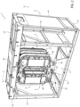
Figure 4 shows a perspective view of a variation of the detail ofFigure 2 , with parts removed for clarity; - Number 1 indicates as a whole a package forming apparatus for producing packages 2, preferentially sealed packages, of a pourable product, in particular a pourable food product, such as milk, milk drinks, yoghurt, yoghurt drinks, fruit juice, wine, tomato sauce, emulsions, beverages containing pulp, salt, sugar, etc., from a
tube 3, preferentially advancing along a tube advancement path P and preferentially being filled with the pourable product. - Preferentially, package forming apparatus 1 may be part of a packaging machine configured to produce packages 2 of the pourable product.
- In more detail, the packaging machine may be preferentially configured to produce packages 2 from a multilayer packaging material; preferentially, the multilayer packaging material may have heat-seal properties (i.e. portions of the multilayer packaging material can be sealed to one another).
- In further detail, the multilayer packaging material may comprise at least one layer of fibrous material, such as e.g. paper or cardboard, and at least two layers of heat-seal plastic material, e.g. polyethylene, interposing the layer of fibrous material in between one another. Preferentially, one of these two layers of heat-seal plastic material may define the inner face of packages 2 contacting the pourable product.
- Moreover, the multilayer packaging material may also comprise a layer of gas- and light-barrier material, e.g. aluminum foil or ethylene vinyl alcohol (EVOH) film, preferentially being arranged between one of the layers of heat-seal plastic material and the layer of fibrous material.
- Preferentially, the packaging material may also comprise a further layer of heat-seal plastic material being interposed between the layer of gas- and light-barrier material and the layer of fibrous material.
- In further detail, the multilayer packaging material may be provided in the form of a web of packaging material.
- Furthermore, the packaging machine may be configured to produce packages 2 by forming
tube 3 from the web of packaging material, longitudinally sealingtube 3,filling tube 3 with the pourable product and by operating package forming apparatus 1 for at least partially shapingtube 3, transversally sealing, and preferentially transversallycutting tube 3. - In more detail, the packaging machine may comprise a tube forming apparatus configured to form and longitudinally
seal tube 3 and a filling apparatus configured to filltube 3 with the pourable product. - Preferentially,
tube 3 may extend along a central axis. - Moreover, the tube forming apparatus may also comprise:
- a conveying unit configured to advance the web of packaging material along a web advancement path, preferentially to a tube forming station, at which, in use, the web of packaging material is formed into
tube 3, and configured to advancetube 3 along tube advancement path P; and - a tube forming and sealing device configured to form
tube 3 from the, in use, advancing web of packaging material and to longitudinallyseal tube 3. - In further detail, the tube forming apparatus may also comprise an isolation chamber, preferentially delimiting an inner environment, in particular a sterile inner environment, from an outer environment. Preferentially, tube forming and sealing device may be at least partially arranged within the isolation chamber, in particular within the inner environment, and being configured to fold and longitudinally
seal tube 3 within the isolation chamber, in particular within the inner environment. - Moreover, the packaging machine may also comprise a sterilization unit configured to sterilize the, in use, advancing web of packaging material, preferentially the sterilization unit being arranged upstream of the tube forming apparatus.
- Preferentially, package forming apparatus 1 may be arranged downstream of the tube forming apparatus and may be configured to receive
tube 3 from the tube forming apparatus. - In further detail and with particular reference to
Figure 1 , package forming apparatus 1 may be configured to manipulatetube 3 being formed from the web of packaging material. - Packaging forming apparatus 1 comprises a first
operative unit 4 and a secondoperative unit 5 spaced apart from one another and defining an advancement space 6 within which, in use,tube 3 advances, when firstoperative unit 4 and secondoperative unit 5 are controlled in an operative configuration. - Preferentially, first
operative unit 4 and secondoperative unit 5 are configured to cooperate with one another so as to manipulatetube 3 for forming packages 2 from the, in use, advancingtube 3, when being controlled in the operative configuration. - As will be explained in more detail further below, first
operative unit 4 and secondoperative unit 5 are also controllable in an idle configuration different from the operative configuration. - It should be noted that there may be a plurality of specific arrangements of first
operative unit 4 and secondoperative unit 5 when being in the idle configuration, i.e. there is not only one single (unique) idle configuration but preferentially a plurality of configurations of firstoperative unit 4 and secondoperative unit 5 define the idle configuration. - Preferentially, when first
operative unit 4 and secondoperative unit 5 are controlled in the idle configuration maintenance operations of firstoperative unit 4 and secondoperative unit 5 are facilitated. - In particular, first
operative unit 4 and second operative 5 may be spaced apart from one another along a direction transversal, preferentially perpendicular, to tube advancement path P. - In more detail, each one of first
operative unit 4 and secondoperative unit 5 comprises: - a plurality of respective
operative devices 7, each one configured to manipulate in collaboration with anotheroperative device 7tube 3 for forming packages 2 fromtube 3; and - a
respective conveyor device 8 configured to advance the respective plurality ofoperative devices 7 along a respective advancement path Q, preferentially an endless advancement path Q. - More specifically, each
operative device 7 of firstoperative unit 4 is configured to cooperate with a respectiveoperative device 7 of secondoperative unit 5 for manipulating, preferentially at least partially shaping and/or transversally sealing and/or transversallycutting tube 3 for forming packages 2 fromtube 3. - Even more specifically, each
operative device 7 of firstoperative unit 4 and the respectiveoperative device 7 of secondoperative unit 5 may form a respective pair ofoperative devices 7 configured to cooperate with one another for manipulatingtube 3. - With particular reference to
Figures 2 and4 , package forming apparatus 1 further comprises asupport frame 9 carrying firstoperative unit 4 and secondoperative unit 5. - More specifically,
support frame 9 defines and/or delimits aninner space 10. Moreover,tube 3 may advance, in use, from the inner environment delimited by the isolation chamber intoinner space 10. - Additionally, advancement space 6 may be arranged within and/or may correspond to a portion of
inner space 10. - According to some preferred non-limiting embodiments,
support frame 9 may carry the isolation chamber. More specifically, the isolation chamber may vertically erect fromsupport frame 9. - Moreover, in use, while first
operative unit 4 and secondoperative unit 5 manipulatetube 3 for forming packages 2, firstoperative unit 4 and secondoperative unit 5 are arranged withininner space 10. - In further detail,
support frame 9 may comprise asupport platform 11. Preferentially, firstoperative unit 4 and secondoperative unit 5 may be connected to and/or carried bysupport platform 11. In particular,support platform 11 may be arranged at a first terminal portion ofsupport frame 9. - Additionally, first
operative unit 4 and secondoperative unit 5 may also be connected to aconnection portion 13 ofsupport frame 9,preferentially connection portion 13 may be opposed to supportplatform 11. More preferentially,connection portion 13 may be arranged at a second terminal portion ofsupport frame 9. - First
operative unit 4 and secondoperative unit 5 may be interposed betweensupport frame 9 andconnection portion 13. - In further detail and with particular reference to
Figures 2 to 4 , firstoperative unit 4 and secondoperative unit 5 are controllable in the operative configuration in which firstoperative unit 4 and secondoperative unit 5 are configured to manipulatetube 3 and the idle configuration in which firstoperative unit 4 and secondoperative unit 5 are controlled away from the operative configuration. In other words, firstoperative unit 4 and secondoperative unit 5 are in a nominal position for being able to manipulatetube 3 for forming packages 2 when being in the operative configuration. When being in the idle configuration, firstoperative unit 4 and secondoperative unit 5 are not able to manipulatetube 3. In particular, when being in the idle configuration, it may be possible to execute maintenance work on firstoperative unit 4 and/or secondoperative unit 5. - It should be noted that advantageously first
operative unit 4 and secondoperative unit 5 are arranged withininner space 10 when being controlled in the operative configuration. -
Figures 1 and2 shows firstoperative unit 4 and secondoperative unit 5 being in the operative configuration.Figure 2 illustrates that firstoperative unit 4 and secondoperative unit 5 are fully arranged withininner space 10. -
Figure 3 shows firstoperative unit 4 and secondoperative unit 5 being in the idle configuration. It should be considered that firstoperative unit 4 and secondoperative unit 5 may take different specific positions when being in the idle configuration. This is for example shown when comparing the configuration ofFigure 3 with the configuration ofFigure 4. Figure 4 illustrates a variation of a portion of firstoperative unit 4 and secondoperative unit 5. - Advantageously, at least one of first
operative unit 4 and secondoperative unit 5, preferentially each one firstoperative unit 4 and secondoperative unit 5, is/are angularly movable about a respective rotation axis A, preferentially being parallel to tube advancement path P and/or having a respective vertical orientation. - According to the example shown, first
operative unit 4 and secondoperative unit 5 are rotatable about the same rotation axis A. According to an alternative embodiment not shown, firstoperative unit 4 and secondoperative unit 5 are each rotatable about a respective rotation axis A, rotation axis A of firstoperative unit 4 being distinct from rotation axis A of secondoperative unit 5. According to an even other embodiment not shown, only one of firstoperative unit 4 and secondoperative unit 5 may be rotatable about rotation axis A, while the other one of firstoperative unit 4 and secondoperative unit 5 may be fixed in space and with respect to supportframe 9. - Moreover, first
operative unit 4 and secondoperative unit 5 are configured such that an angular movement of at least one of firstoperative unit 4 and secondoperative unit 5 and/or of both firstoperative unit 4 and secondoperative unit 5 about the respective rotation axis A allows to control firstoperative unit 4 and secondoperative unit 5 between the respective operative configuration and the respective idle configuration. - In further detail, each one of first
operative unit 4 and secondoperative unit 5 may be arranged in a respective first angular position with respect to the respective rotation axes A when being in the operative configuration. - Additionally, when being controlled in the idle configuration, the respective angular position of first
operative unit 4 and/or of secondoperative unit 5 with respect to the respective rotation axes A may be different from the respective first angular position. - It should be noted that it is possible to move first
operative unit 4 and secondoperative unit 5 away from the operative configuration by e.g. changing the angular position of one or both of firstoperative unit 4 and secondoperative unit 5. - In the idle configuration shown
Figure 3 the firstoperative unit 4 and the secondoperative unit 5 have been rotated of an angle of 180 degrees about the respective rotation axes A compared to the operative configuration shown inFigure 2 . - When reverting to
Figure 2 , one notes that the angular positions of firstoperative unit 4 and the angular position of secondoperative unit 5 with respect to the respective rotation axes A correspond to the respective first angular position and firstoperative unit 4 and secondoperative unit 5 are arranged withininner space 10. - When reverting to
Figure 3 one notes that both firstoperative unit 4 and secondoperative unit 5 have been angularly moved about the respective rotation axes A and both firstoperative unit 4 and secondoperative unit 5 are arranged in respective second angular positions with respect to the respective rotation axes A. One notes that a technical operator may easily access the space formed between firstoperative unit 4 and secondoperative unit 5 such as to perform maintenance activities. - When reverting to
Figure 3 , one notes that firstoperative unit 4 and secondoperative unit 5 may also be positionable at least partially within anouter space 12 defined bysupport frame 9 and with firstoperative unit 4 and secondoperative unit 5 being controlled in the idle configuration. Preferentially, in such a situation, the respective second angular position of firstoperative unit 4 and the respective second angular position of secondoperative unit 5 with respect to the respective rotation axes A differ from the respective first angular positions. - For this reason, preferentially support
platform 11 andconnection portion 13 ofsupport frame 9 may be arranged at a lateral section ofsupport frame 9. - According to some preferred non-limiting embodiments, the respective rotation axis A of first
operative unit 4 and the respective rotation axis A of secondoperative unit 5 coincide. - According to some preferred non-limiting embodiments, first
operative unit 4 and secondoperative unit 5 may be angularly moveably connected to supportplatform 11 andconnection portion 13 ofsupport frame 9. - Preferentially, rotation axis A may extend between and/or may be defined by
support platform 11 andconnection portion 13 ofsupport frame 9. - With particular reference to
Figure 4 , each one of the firstoperative unit 4 and secondoperative unit 5 may comprise at least onerespective abutment surface 15 abutting against one another with firstoperative unit 4 and secondoperative unit 5 being controlled in the operative configuration. According to the variation ofFigure 4 , each one of firstoperative unit 4 and secondoperative unit 5 may comprise two respective abutment surfaces 15, while in the variation ofFigures 2 and3 , each one of firstoperative unit 4 and secondoperative unit 5 may comprise only onerespective abutment surface 15. - Additionally, first
operative unit 4 may comprise one or morefirst interaction elements 16 and secondoperative unit 5 may comprise one or moresecond interaction element 17. Eachfirst interaction element 16 may be configured to engage and/or interact with a respectivesecond interaction element 17 with firstoperative unit 4 and secondoperative unit 5 being controlled in the operative configuration, in particular so as to guarantee that firstoperative unit 4 and secondoperative unit 5 are correctly arranged (and maintained) in the operative position. - Preferentially, each
first interaction element 16 and the respectivesecond interaction element 17 may be complementary to one another. - In further detail, each
first interaction element 16 may be chosen from a group comprising pins, bars and rods and eachsecond interaction element 17 may be chosen from a group comprising holes, grooves and slots. - According to some preferred non-limiting embodiments, package forming apparatus 1 may further comprise a first locking device configured to lock first
operative unit 4 and secondoperative unit 5 in the operative configuration. - Additionally or alternatively, package forming apparatus 1 may comprise a second locking device configured to lock first
operative unit 4 and the secondoperative unit 5 in the idle configuration. - According to some possible embodiments, first
operative unit 4 and/or secondoperative unit 5 may comprise at least a portion of the first locking device and/or the second locking device and/orsupport frame 9 may comprise another portion of the first locking device and/or the second locking device configured to cooperate with the respective portion of, respectively, the first locking device and the second locking device. - According to some possible non-limiting embodiments, package forming apparatus 1 may further comprise a
delimitation element 18. Moreover, at least one of firstoperative unit 4 and secondoperative unit 5 may abut againstdelimitation element 18 with firstoperative unit 4 and secondoperative unit 5 being in the operative configuration and for guaranteeing, in use, a desired position of the firstoperative unit 4 and secondoperative unit 5 with respect totube 3. In other words, delimitationelement 18 may be configured to guarantee that firstoperative unit 4 and secondoperative unit 5 may be arranged in the respective first angular position with firstoperative unit 4 and second operative unit being arranged in the operative configuration. - Preferentially,
support frame 9, more preferentially supportplatform 11, may carry delimitingelement 18. - In further detail and with particular reference to
Figures 2 and3 ,support frame 9 may comprises a plurality ofbars 19, e.g. some having vertical orientations and some other having horizontal orientations. Additionally,support frame 9 may also comprise a plurality of wall elements 20 (only some shown) interposed betweenrespective bars 19.Support frame 9 may also comprise one or more doors (not shown) selectively movable between respective open positions and closed positions for, respectively, allowing to accessinner space 10 and impeding to accessinner space 10. Additionally, one or more doors may be configured to be arranged in the respective open position so as to allow to position firstoperative unit 4 and secondoperative unit 5 inouter space 12. - In further detail and with particular reference to
Figures 2 to 4 , each one of firstoperative unit 4 and secondoperative unit 5 may comprise arespective support structure 21 carrying the respectiveoperative devices 7 and the respective conveyingdevice 8. - Each
support structure 21 may be angularly movable about the respective rotation axis A. - Moreover, each
support structure 21 may be hinged to supportframe 9, preferentially supportplatform 11 andconnection portion 13 ofsupport frame 9, and the respective hinge axis may define the respective rotation axis A. - According to some preferred non-limiting embodiments, each
support structure 21 may be hinged to supportframe 9 at a firstlateral portion 22. - Additionally, each
support structure 21 may comprise a secondlateral portion 23 opposed to the respective firstlateral portion 22. Preferentially, each secondlateral portion 23 may comprise the respective abutment surface(s) 15. - According to the variant of
Figures 2 and3 , the respective abutment surfaces 15 may be in respective central portions of firstoperative unit 4 and of secondoperative unit 5, while in the variant ofFigure 4 , the respective abutment surfaces 15 may be arranged at respective end sections of the respectivelateral portions 23. - In further detail,
support platform 11 may comprise asupport pillar 24 and eachsupport structure 21, preferentially the respective firstlateral portion 22, may comprise afirst coupling element 25, preferentially provided with a respective through-hole, being angularly moveably coupled to supportpillar 24. In particular,first coupling elements 25 may be arranged on top of one another. - Additionally, each
support structure 21 may also comprise a respectivesecond coupling element 26 opposed to the respectivefirst coupling element 25, and preferentially comprising a respective through-hole. Preferentially, the respectivesecond coupling elements 26 may be arranged on top of one another. - Preferentially,
connection portion 13 ofsupport frame 9 may comprise acoupling pin 27, preferentially protruding towardssupport platform 11. - Preferentially, each
second coupling element 26 may be angularly moveably coupled tocoupling pin 27. - According to some preferred non-limiting embodiments, each conveying
device 8 may be configured to advance the respectiveoperative devices 7 along a respective operative portion Q1 and a respective return portion Q2 of the respective advancement path Q. - More specifically, each
operative device 7 may be configured to manipulatetube 3 and being retracted fromtube 3 when advancing, in use, along, respectively, the respective operative portion Q1 and the respective return portion Q2. In other words, eachoperative device 7 may be configured to manipulatetube 3 when advancing along the respective operative portion of advancement path Q1. - Additionally, each
operative device 7 may be controlled from a respective rest configuration to a respective operative configuration while advancing along the respective operative portion Q1. In particular, eachoperative device 7 may be configured to manipulate, preferentially to at least partially shape and/or transversally seal and/or transversally cut,tube 3 when being controlled in the respective operative configuration. Moreover, eachoperative device 7 may be configured to be retracted fromtube 3 when being controlled in the respective rest configuration. - Preferentially, each
operative device 7 may be controlled in the respective rest configuration while advancing along the respective return portion Q2 of advancement path Q. - In further detail, each
operative device 7 may advance along the same direction astube 3 while advancing along the respective operative portion Q1. - More specifically and with particular reference to
Figure 3 , eachoperative device 7 may comprise: - a half-
shell 36 configured to at least partially shapetube 3, preferentially with the respectiveoperative device 7 being controlled in the respective operative configuration; and - one of a sealing element or a counter-sealing element, configured to transversally
seal tube 3 between adjacent packages 2, preferentially with the respectiveoperative device 7 being controlled in the operative configuration. - According to some possible embodiments, each
operative device 7 of firstoperative unit 4 may comprise a respective counter-sealing element and eachoperative device 7 of secondoperative unit 5 may comprise a respective sealing element. Alternatively, eachoperative device 7 of firstoperative unit 4 may comprise a respective sealing element and eachoperative device 7 of secondoperative unit 5 may comprise a respective counter-sealing element. - It should be further noted that each
operative device 7 having a respective sealing element is configured to cooperate with a respectiveoperative device 7 having a counter-sealing element. In this way, each sealing element and the respective counter-sealing element are configured to transversally flat-lay tube 3 and to transversally seal tube in cooperation with one another and with the respectiveoperative device 7 being controlled in the respective operative configuration. - In further detail, each half-
shell 36 may be configured to move between at least a first limit position and a second limit position, e.g. by means of an angular and/or linear movement, at which half-shell 36 may be configured to engagetube 3. - Advantageously, each half-
shell 36 may be positioned in the respective first limit position and the respective second limit position with the respectiveoperative device 7 being controlled in respectively the corresponding rest configuration and the corresponding operative configuration. - According to some possible non-limiting embodiments, package forming apparatus 1 may comprise a cam mechanism for controlling half-
shells 36 between the respective rest configurations and the respective operative configurations. - At least some
operative devices 7 may also comprise a cutting element configured to transversally cuttube 3, preferentially with the respectiveoperative device 7 being controlled in the respective operative configuration and after execution of the transversal sealing oftube 3. - Preferentially, each
operative device 7 of firstoperative unit 4 and the respectiveoperative device 7 of secondoperative unit 5 may comprise together one respective cutting element. - In further detail and according to the specific examples shown in
Figures 1 to 4 , eachconveyor device 8 may be configured to control advancement of the respectiveoperative devices 7 along advancement path Q by means of a locally controlled electromagnetic field. - In more detail, each
conveyor device 8 may comprise a plurality ofcarts 37 and acontrol unit 38 configured to advance thecarts 37 along a respective auxiliary advancement path R, preferentially an endless auxiliary advancement path R. In particular, eachcart 37 may be moveably coupled to therespective control unit 38. - Preferentially, each
control unit 38 may be configured to selectively advance eachcart 37 independently from theother carts 37. - Moreover, each
control unit 38 may comprises a plurality of induction coils and may be configured to selectively generate local electromagnetic fields for controlling advancement of therespective carts 37. Additionally, eachcart 37 may comprise one or more magnetic or paramagnetic elements configured to interact with the local electromagnetic fields. - Additionally, each
operative device 7 may be connected to onerespective cart 37, and preferentially may be laterally displaced from therespective cart 37. - Moreover, advancement of
carts 37 along the respective auxiliary advancement paths R lead to advancement of the respectiveoperative devices 7 along the respective advancement paths Q. - Each auxiliary advancement path R may be parallel to the respective advancement path Q.
- In use, the packaging machine forms packages 2 from a web of packaging material, the packages 2 being filled with the pourable product.
- The tube forming apparatus forms
tube 3 from the web of packaging material, the filling apparatus fillstube 3 and package forming apparatus 1 manipulatestube 3 so as to obtain packages 2 filled with the pourable product. - In more detail, during operation of package forming apparatus 1
tube 3 advances through advancement space 6 and firstoperative unit 4 and secondoperative unit 5 cooperate for obtaining packages 2. - More specifically, each
operative device 7 of firstoperative unit 4 cooperates, preferentially cyclically cooperates, with the respectiveoperative device 7 of secondoperative unit 5 for forming respective packages 2 from advancingtube 3. - Additionally, during manipulation of
tube 3 firstoperative unit 4 and secondoperative unit 5 are controlled in the operative configuration. If needed, production may be interrupted and/or stopped and/or ended and firstoperative unit 4 and secondoperative unit 5 may be controlled in the idle configuration. This is done by moving at least one of firstoperative unit 4 and secondoperative unit 5 about the respective rotation axis A. - A technical operator can execute maintenance activities with first
operative unit 4 and secondoperative unit 5 being controlled in the idle configuration. - The advantages of package forming apparatus 1 and/or the packaging machine according to the present invention will be clear from the foregoing description.
- In particular, by having at least one of first
operative unit 4 and secondoperative unit 5 being rotatable about the respective rotation axis A, maintenance work is facilitated. - Furthermore, the possibility of arranging first
operative unit 4 and secondoperative unit 5 in the idle configuration is advantageous in that the technical operator can access parts of firstoperative unit 4 and secondoperative unit 5 fromouter space 12. - Clearly, changes may be made to package forming apparatus 1 and/or the packaging machine as described herein without, however, departing from the scope of protection as defined in the accompanying claims.
- According to some possible embodiments not shown, the plurality of
operative devices 7 of firstoperative unit 4 and the plurality ofoperative devices 7 of secondoperative unit 5 may be connected to one another and/or define a respective endless chain. Additionally, each conveyor device may be configured to advance the respective endless chain along an auxiliary advancement path so as to advance the respectiveoperative devices 7 along the respective advancement path Q.
Claims (15)
- A package forming apparatus (1) for forming packages (2) from a tube (3) filled with a pourable product, the package forming apparatus (1) comprising:- a first operative unit (4) and a second operative unit (4) spaced apart from one another and defining an advancement space (6) within which, in use, the tube (3) advances;wherein each one of the first operative unit (4) and the second operative unit (5) comprises:- a plurality of respective operative devices (7), each operative device (7) of the first operative unit (4) being configured to manipulate in collaboration with a respective operative device (7) of the second operative unit (5) the tube (3) for forming the packages (2); and- a respective conveyor device (8) configured to advance the respective plurality of operative devices (7) along an advancement path (Q);wherein the first operative unit (4) and the second operative unit (5) are controllable in an operative configuration in which the first operative unit (4) and the second operative unit (5) are configured to manipulate the tube (3) and an idle configuration in which the first operative unit (4) and the second operative unit (5) are controlled away from the operative configuration;wherein at least one of the first operative unit (4) and the second operative unit (5) is angularly movable about a rotation axis (A);wherein the first operative unit (4) and the second operative unit (5) are configured such that an angular movement of at least one of the first operative unit (4) and the second operative unit (5) about the respective rotation axis (A) allows to control the first operative unit (4) and the second operative unit (5) between the respective operative configuration and the respective idle configuration.
- Package forming apparatus according to claim 1, wherein both, the first operative unit (4) and the second operative unit (5) are angularly movable about respective rotation axes (A);
wherein an angular movement of the first operative unit (4) and/or the second operative unit (5) about the respective rotation axes (A) allows control of the first operative unit (4) and the second operative unit (5) between the respective operative configuration and the respective idle configuration. - Package forming apparatus according to claim 2, wherein the respective rotation axis (A) of the first operative unit (4) and the respective rotation axis (A) of the second operative unit (5) coincide.
- Package forming apparatus according to any one of the preceding claims, wherein each one of the first operative unit (4) and the second operative unit (5) comprises a respective abutment surface (15), the abutment surface (15) of one of the first operative unit (4) and the second operative unit (5) abutting against the abutment surface (15) of the other one of the first operative unit (4) and the second operative unit (5) with the first operative unit (4) and the second operative unit (5) being controlled in the operative configuration.
- Package forming apparatus according to any one of the preceding claims, wherein the first operative unit (4) comprises one or more first interaction elements (16) and the second operative unit (5) comprises one or more second interaction elements (17);
wherein each first interaction element (16) is configured to engage with a respective second interaction element (17) with the first operative unit (4) and the second operative unit (5) being controlled in the operative configuration. - Package forming apparatus according to claim 5,wherein each first interaction element (16) and the respective second interaction element (17) are complementary to one another and/orwherein each first interaction element (16) is chosen from a group comprising pins, bars and rods and/or each second interaction element (17) is chosen from a group comprising holes, grooves and slots.
- Package forming apparatus according to any one of the preceding claims, and further comprising one first locking device configured to lock the first operative unit (4) and the second operative unit (5) in the operative configuration; and/or
a second locking device configured to lock the first operative unit (4) and the second operative unit (5) in the idle configuration. - Package forming apparatus according to any one of the preceding claims, and further comprising a delimitation element (18);
wherein at least one of the first operative unit (4) and the second operative unit (5) abuts against the delimitation element (18) with the first operative unit (4) and the second operative unit (5) being in the operative configuration and for guaranteeing, in use, a desired position of the first operative unit (4) and the second operative unit (5) with respect to the tube (3). - Package forming apparatus according to any one of the preceding claims, and further comprising a support frame (9) ;
wherein the support frame (9) carries the first operative unit (4) and the second operative unit (5). - Package forming apparatus according to claim 9, wherein the support frame (9) comprises a support platform (11) and the first operative unit (4) and the second operative unit (5) are angularly moveably connected to the support platform (11);wherein the first operative unit (4) and the second operative unit (5) are also angularly moveably connected to a connection portion (13) of the support frame (9);wherein the rotation axis (A) extends between the support platform (11) and the connection portion (13) of the support frame (9);wherein both the first operative unit (4) and the second operative unit (5) are angularly movable about the same rotation axis (A).
- Package forming apparatus according to claim 9 or 10, wherein the support frame (9) defines and/or comprises an inner space (11);
wherein the first operative unit (4) and the second operative unit (5) are arranged within the inner space (11) when being controlled in the operative configuration. - Package forming apparatus according to claim 11, wherein the first operative unit (4) and the second operative unit (5) are at least partially positionable within an outer space (12) defined by the support frame (9) and with the first operative unit (4) and the second operative unit (5) being arranged in the idle configuration.
- Package forming apparatus according to any one of the preceding claims, wherein the tube (3) advances, in use, along a tube advancement path (P) andeach rotation axis (A) is parallel to the tube advancement path (P); and/oreach rotation axis (A) has a substantially vertical orientation.
- Package forming apparatus according to any one of the preceding claims, wherein each conveyor device (8) comprises a plurality of carts (37) and is configured to advance the plurality of carts (37) along an auxiliary advancement path (P);wherein each operative device (7) is connected to the respective cart (37);wherein advancement of each cart (37) along the respective auxiliary advancement path (R) leads to advancement of the respective operative devices (7) along the advancement path (Q); orthe plurality of operative devices (7) of the first operative unit (4) and the plurality of operative devices (7) of the respective second operative unit (5) are connected to one another and/or define a respective endless chain;wherein each conveyor device is configured to advance the respective chain along an endless advancement path.
- Packaging machine for forming packages (2) filled with a pourable product comprising a tube forming apparatus configured to form a tube (3) from a web of packaging material and a package forming apparatus (1) according to any one of the preceding claims and being configured to form the packages (2) from the tube (3).
Applications Claiming Priority (1)
| Application Number | Priority Date | Filing Date | Title |
|---|---|---|---|
| IT102023000011751A IT202300011751A1 (en) | 2023-06-08 | 2023-06-08 | PACKAGE FORMING APPARATUS AND PACKAGING MACHINE FOR FORMING PACKAGES |
Publications (1)
| Publication Number | Publication Date |
|---|---|
| EP4474297A1 true EP4474297A1 (en) | 2024-12-11 |
Family
ID=87801630
Family Applications (1)
| Application Number | Title | Priority Date | Filing Date |
|---|---|---|---|
| EP24179162.3A Pending EP4474297A1 (en) | 2023-06-08 | 2024-05-31 | Package forming apparatus and packaging machine for forming packages |
Country Status (4)
| Country | Link |
|---|---|
| EP (1) | EP4474297A1 (en) |
| CN (1) | CN121335840A (en) |
| IT (1) | IT202300011751A1 (en) |
| WO (1) | WO2024251615A1 (en) |
Citations (4)
| Publication number | Priority date | Publication date | Assignee | Title |
|---|---|---|---|---|
| US5001891A (en) * | 1989-06-06 | 1991-03-26 | Italpack S.R.L. | Filling and packaging machine |
| US5511363A (en) * | 1993-04-22 | 1996-04-30 | Klockner Hansel Gmbh | Vertical cyclically operating flat sack machine |
| US20110120059A1 (en) * | 2008-08-09 | 2011-05-26 | Tetra Laval Holdings & Finance S.A. | Packaging method and unit for producing sealed packages of a food product pourable into a tube of packaging material |
| EP3254980A1 (en) | 2016-06-09 | 2017-12-13 | Tetra Laval Holdings & Finance S.A. | A packaging apparatus for forming sealed packages from a tube of packaging material |
-
2023
- 2023-06-08 IT IT102023000011751A patent/IT202300011751A1/en unknown
-
2024
- 2024-05-31 WO PCT/EP2024/064979 patent/WO2024251615A1/en not_active Ceased
- 2024-05-31 EP EP24179162.3A patent/EP4474297A1/en active Pending
- 2024-05-31 CN CN202480038350.9A patent/CN121335840A/en active Pending
Patent Citations (4)
| Publication number | Priority date | Publication date | Assignee | Title |
|---|---|---|---|---|
| US5001891A (en) * | 1989-06-06 | 1991-03-26 | Italpack S.R.L. | Filling and packaging machine |
| US5511363A (en) * | 1993-04-22 | 1996-04-30 | Klockner Hansel Gmbh | Vertical cyclically operating flat sack machine |
| US20110120059A1 (en) * | 2008-08-09 | 2011-05-26 | Tetra Laval Holdings & Finance S.A. | Packaging method and unit for producing sealed packages of a food product pourable into a tube of packaging material |
| EP3254980A1 (en) | 2016-06-09 | 2017-12-13 | Tetra Laval Holdings & Finance S.A. | A packaging apparatus for forming sealed packages from a tube of packaging material |
Also Published As
| Publication number | Publication date |
|---|---|
| WO2024251615A1 (en) | 2024-12-12 |
| CN121335840A (en) | 2026-01-13 |
| IT202300011751A1 (en) | 2024-12-08 |
Similar Documents
| Publication | Publication Date | Title |
|---|---|---|
| US10549485B2 (en) | Packaging apparatus for forming sealed packages from a tube of packaging material | |
| EP3760548B1 (en) | A packaging assembly for forming and sealing a plurality of packs containing a pourable product and a method for forming and sealing a plurality of packs | |
| US12043442B2 (en) | Package forming unit, packaging apparatus having a package forming unit and method for forming packages | |
| EP4357253A1 (en) | Folding apparatus and packaging machine having a folding apparatus | |
| EP4310027B1 (en) | Conveying apparatus for a packaging machine and packaging machine having a conveying apparatus | |
| EP4357255A1 (en) | Folding apparatus and packaging machine having a folding apparatus | |
| WO2024251615A1 (en) | Package forming apparatus and packaging machine for forming packages | |
| EP4265533A1 (en) | Infeed conveyor for a folding apparatus, folding apparatus having an infeed conveyor and packaging machine having a folding apparatus | |
| EP4474299A1 (en) | Package forming apparatus and packaging machine for forming packages | |
| EP4458689A1 (en) | Package forming apparatus for a packaging machine, packaging machine for forming packages filled with a pourable product and method for forming packages | |
| EP4549329A1 (en) | Package forming apparatus for a packaging machine and packaging machine for forming packages filled with a pourable product | |
| EP4410690B1 (en) | Package forming apparatus for a packaging machine and packaging machine for forming packages filled with a pourable product | |
| EP4357254A1 (en) | Folding apparatus and packaging machine having a folding apparatus | |
| EP4656538A1 (en) | Folding apparatus, packaging machine having a folding apparatus and method for forming finalized packages from semi-finalized packs | |
| EP4454864A1 (en) | Package forming apparatus for a packaging machine and packaging machine for forming packages filled with a pourable product | |
| EP4656539A1 (en) | Folding apparatus, packaging machine having a folding apparatus and method for forming finalized packages from semi-finalized packs | |
| EP4410692A1 (en) | Package forming apparatus for a packaging machine and packaging machine for forming packages filled with a pourable product | |
| EP4410524A1 (en) | Package forming apparatus for a packaging machine and packaging machine for forming packages filled with a pourable product | |
| EP4410522B1 (en) | Package forming apparatus for a packaging machine and packaging machine for forming packages filled with a pourable product | |
| EP4656535A1 (en) | Folding apparatus, packaging machine having a folding apparatus and method for forming finalized packages from semi-finalized packs | |
| EP4656534A1 (en) | Infeed conveyor for a folding apparatus, folding apparatus having an infeed conveyor and packaging machine having a folding apparatus for forming finalized packages from semi-finalized packs | |
| EP4371893A1 (en) | Filling machine for filling a pourable product into receptacles |
Legal Events
| Date | Code | Title | Description |
|---|---|---|---|
| PUAI | Public reference made under article 153(3) epc to a published international application that has entered the european phase |
Free format text: ORIGINAL CODE: 0009012 |
|
| STAA | Information on the status of an ep patent application or granted ep patent |
Free format text: STATUS: THE APPLICATION HAS BEEN PUBLISHED |
|
| AK | Designated contracting states |
Kind code of ref document: A1 Designated state(s): AL AT BE BG CH CY CZ DE DK EE ES FI FR GB GR HR HU IE IS IT LI LT LU LV MC ME MK MT NL NO PL PT RO RS SE SI SK SM TR |
|
| STAA | Information on the status of an ep patent application or granted ep patent |
Free format text: STATUS: REQUEST FOR EXAMINATION WAS MADE |
|
| 17P | Request for examination filed |
Effective date: 20250611 |