EP4474269A1 - Spring guided hand actuator for aircraft component - Google Patents
Spring guided hand actuator for aircraft component Download PDFInfo
- Publication number
- EP4474269A1 EP4474269A1 EP24181186.8A EP24181186A EP4474269A1 EP 4474269 A1 EP4474269 A1 EP 4474269A1 EP 24181186 A EP24181186 A EP 24181186A EP 4474269 A1 EP4474269 A1 EP 4474269A1
- Authority
- EP
- European Patent Office
- Prior art keywords
- guide element
- pivot axis
- support structure
- handle
- handle structure
- Prior art date
- Legal status (The legal status is an assumption and is not a legal conclusion. Google has not performed a legal analysis and makes no representation as to the accuracy of the status listed.)
- Pending
Links
Images


Classifications
-
- G—PHYSICS
- G05—CONTROLLING; REGULATING
- G05G—CONTROL DEVICES OR SYSTEMS INSOFAR AS CHARACTERISED BY MECHANICAL FEATURES ONLY
- G05G1/00—Controlling members, e.g. knobs or handles; Assemblies or arrangements thereof; Indicating position of controlling members
- G05G1/02—Controlling members for hand actuation by linear movement, e.g. push buttons
-
- F—MECHANICAL ENGINEERING; LIGHTING; HEATING; WEAPONS; BLASTING
- F16—ENGINEERING ELEMENTS AND UNITS; GENERAL MEASURES FOR PRODUCING AND MAINTAINING EFFECTIVE FUNCTIONING OF MACHINES OR INSTALLATIONS; THERMAL INSULATION IN GENERAL
- F16C—SHAFTS; FLEXIBLE SHAFTS; ELEMENTS OR CRANKSHAFT MECHANISMS; ROTARY BODIES OTHER THAN GEARING ELEMENTS; BEARINGS
- F16C1/00—Flexible shafts; Mechanical means for transmitting movement in a flexible sheathing
- F16C1/10—Means for transmitting linear movement in a flexible sheathing, e.g. "Bowden-mechanisms"
- F16C1/12—Arrangements for transmitting movement to or from the flexible member
- F16C1/16—Arrangements for transmitting movement to or from the flexible member in which the end-piece is guided rectilinearly
-
- G—PHYSICS
- G05—CONTROLLING; REGULATING
- G05G—CONTROL DEVICES OR SYSTEMS INSOFAR AS CHARACTERISED BY MECHANICAL FEATURES ONLY
- G05G5/00—Means for preventing, limiting or returning the movements of parts of a control mechanism, e.g. locking controlling member
- G05G5/05—Means for returning or tending to return controlling members to an inoperative or neutral position, e.g. by providing return springs or resilient end-stops
-
- B—PERFORMING OPERATIONS; TRANSPORTING
- B64—AIRCRAFT; AVIATION; COSMONAUTICS
- B64D—EQUIPMENT FOR FITTING IN OR TO AIRCRAFT; FLIGHT SUITS; PARACHUTES; ARRANGEMENT OR MOUNTING OF POWER PLANTS OR PROPULSION TRANSMISSIONS IN AIRCRAFT
- B64D29/00—Power-plant nacelles, fairings or cowlings
- B64D29/06—Attaching of nacelles, fairings or cowlings
Definitions
- This disclosure relates generally to an aircraft and, more particularly, to an actuator for actuating a component of the aircraft.
- An aircraft may include a component which is actuated with a hand actuator.
- a hand actuator Various types of hand actuators are known in the art. While these known hand actuators have various benefits, there is still room in the art for improvement.
- an assembly for an aircraft.
- This aircraft assembly includes an actuator and a cable assembly.
- the actuator includes a support structure, a handle structure and a guide system configured to guide movement of the handle structure longitudinally along the support structure between a first position and a second position.
- the guide system includes a first guide element and a second guide element.
- the first guide element includes a first spring element and is pivotally coupled to the handle structure at a handle structure pivot axis.
- the second guide element includes a second spring element and is pivotally coupled to the handle structure at the handle structure pivot axis.
- the cable assembly includes a sleeve and a cable projecting longitudinally out of the sleeve. The sleeve is attached to the support structure. The cable is coupled to the handle structure.
- This aircraft assembly includes a support structure, a handle structure, a slide, a first guide element and a second guide element.
- the support structure includes a handle mount and a track.
- the handle structure projects longitudinally through an aperture in the handle mount.
- the slide is coupled to the handle structure and is mated with the track.
- the slide is configured to move longitudinally along the track.
- the first guide element is pivotally coupled to the handle structure at a handle structure pivot axis.
- the first guide element is pivotally coupled to the support structure at a first support structure pivot axis.
- the first guide element includes a first spring element.
- the second guide element is pivotally coupled to the handle structure at the handle structure pivot axis.
- the second guide element is pivotally coupled to the support structure at a second support structure pivot axis which is offset from the first support structure pivot axis.
- the second guide element includes a second spring element.
- This aircraft assembly includes a support structure, a handle structure and a plurality of guide elements.
- the support structure includes a first wall, a second wall and a channel laterally between the first wall and the second wall.
- the handle structure projects longitudinally into the channel.
- the guide elements are pivotally coupled to the handle structure at a handle structure pivot axis.
- Each of the guide elements includes a spring element.
- the guide elements include a first lower guide element, a second lower guide element, a first upper guide element and a second upper guide element.
- the first lower guide element is pivotally coupled to the first wall at a lower support structure pivot axis.
- the second lower guide element is pivotally coupled to the second wall at the lower support structure pivot axis.
- the first upper guide element is pivotally coupled to the first wall at an upper support structure pivot axis.
- the second upper guide element is pivotally coupled to the second wall at the upper support structure pivot axis.
- the first guide element and the second guide element may be disposed to opposing sides of the handle structure.
- the support structure may include a wall.
- the first guide element may be pivotally coupled to the wall at a first support structure pivot axis.
- the second guide element may be pivotally coupled to the wall at a second support structure pivot axis which is offset from the first support structure pivot axis.
- the second support structure pivot axis may be longitudinally aligned with the first support structure pivot axis.
- the wall may be a first wall.
- the support structure may also include a second wall.
- the handle structure may be disposed laterally between the first wall and the second wall.
- the guide system may also include a third guide element and a fourth guide element.
- the third guide element may include a third spring element.
- the third guide element may be pivotally coupled to the handle structure at the handle structure pivot axis.
- the third guide element may be pivotally coupled to the second wall at a third support structure pivot axis.
- the fourth guide element may include a fourth spring element.
- the fourth guide element may be pivotally coupled to the handle structure at the handle structure pivot axis.
- the fourth guide element may be pivotally coupled to the second wall at a fourth support structure pivot axis which is offset from the third support structure pivot axis.
- the third support structure pivot axis may be coaxial with the first support structure pivot axis.
- the fourth support structure pivot axis may be coaxial with the second support structure pivot axis.
- the first guide element may pivot between seventy degrees and one-hundred and ten degrees about the handle structure pivot axis as the handle structure moves longitudinally from the first position to the second position.
- the second guide element may pivot between seventy degrees and one-hundred and ten degrees about the handle structure pivot axis as the handle structure moves longitudinally from the first position to the second position.
- the first guide element may have a first guide element centerline.
- the first guide element may extend along the first guide element centerline to the handle structure pivot axis.
- the second guide element may have a second guide element centerline.
- the second guide element may extend along the second guide element centerline to the handle structure pivot axis.
- the first guide element centerline may be angularly offset from the second guide element centerline by a first position angle when the handle structure is in the first position.
- the first guide element centerline may be angularly offset from the second guide element centerline by a second position angle when the handle structure is in the second position.
- the second position angle may be equal to the first position angle.
- the first guide element centerline may be parallel with the second guide element centerline when the handle structure is in an intermediate position longitudinally between the first position and the second position.
- the first spring element may be configured as or otherwise include a first coil spring.
- the second spring element may be configured as or otherwise include a second coil spring.
- the first spring element and the second spring element may each be compressed when the handle structure is in the first position. In addition or alternatively, the first spring element and the second spring element may each be compressed when the handle structure is in the second position.
- the guide system may also include a track and a slide configured to move longitudinally along the track.
- the track may be configured with the support structure.
- the slide may be configured with the handle structure.
- the handle structure pivot axis may be a centerline axis of the slide.
- the support structure may include a handle mount.
- the handle structure may include a handle and a strut.
- the strut may project longitudinally out from the handle and through an aperture in the handle mount.
- the first guide element, the second guide element and the cable may be coupled to the strut.
- the aircraft assembly may also include a cowl and a hold open rod.
- the cowl may be configured to pivot between a closed position and an open position.
- the hold open rod may be configured to hold the cowl in the open position.
- the actuator may be operatively coupled to the hold open rod through the cable.
- the aircraft assembly may also include a lock operatively coupled to and actuatable by the actuator through the cable.
- the present disclosure may include any one or more of the individual features disclosed above and/or below alone or in any combination thereof.
- FIG. 1 illustrates an assembly 10 for an aircraft such as, but not limited to, a commercial airliner or cargo plane.
- This aircraft assembly 10 includes a positive locking hand (e.g., manual) actuator 12 and another component 14 of the aircraft operatively coupled to the hand actuator 12 through a cable assembly 16 (and/or another linkage arrangement).
- the aircraft component 14 may be configured as or otherwise include a hold open rod ("HOR") for a nacelle cowl or another type of aircraft door or hatch.
- the aircraft component 14 may also or alternatively be configured as or otherwise include a lock for still another component of the aircraft; e.g., the hold open rod, the nacelle cowl or another type of aircraft door or hatch.
- HOR hold open rod
- the present disclosure is not limited to the foregoing exemplary aircraft component configurations.
- the aircraft component 14, may be configured as or otherwise include any device (or devices) which may be actuated or otherwise moved utilizing the hand actuator 12; e.g., the hand actuator 12 may be or may be coupled to an opening mechanism for an aircraft door or hatch.
- the hand actuator 12 of FIG. 1 includes a support structure 18, a handle structure 20 and a positive locking guide system 22.
- the support structure 18 extends longitudinally between and to a longitudinal first end 24 of the support structure 18 and a longitudinal second end 26 of the support structure 18.
- the support structure 18 extends vertically between and to a lower side 28 of the support structure 18 and an upper side 30 of the support structure 18.
- the terms “lower” and “upper” may be used herein to describe an orientation of the hand actuator 12 and its various components with respect to the arrangement shown in FIG. 1 .
- the terms “lower” and “upper”, however, are not intended to limit the orientation of the hand actuator 12 and its various components to any specific orientation relative to gravity.
- the support structure 18 of FIG. 1 includes a mounting base 32, one or more walls 34A and 34B (generally referred to as "34"), a handle mount 36 and a cable mount 38.
- the mounting base 32 is disposed at (e.g., on, adjacent or proximate) the support structure lower side 28. This mounting base 32 is configured to provide a platform for mounting the hand actuator 12 to a (e.g., stationary) structure of the aircraft.
- the mounting base 32 of FIG. 1 extends longitudinally from the support structure first end 24 (e.g., towards the support structure second end 26) to a second end 40 of the mounting base 32, which mounting base second end 40 of FIG. 1 is longitudinally spaced (e.g., recessed) inward from the support structure second end 26.
- the mounting base second end 40 may alternatively be located at the support structure second end 26.
- Each of the walls 34 is connected to (e.g., formed integral with or otherwise attached to) and may be perpendicular to the mounting base 32. Each of the walls 34 projects vertically out from the mounting base 32 to a respective distal end 42 of that wall 34, which wall end 42 is disposed at the support structure upper side 30.
- Each of the walls 34 of FIG. 1 extends longitudinally from the support structure first end 24 (e.g., towards the support structure second end 26) to the mounting base second end 40.
- the walls 34 are laterally spaced apart from one another thereby forming a channel 44 in the support structure 18. This channel 44 extends longitudinally along each of the walls 34.
- the channel 44 extends laterally within the support structure 18 between the walls 34.
- the channel 44 of FIG. 1 extends vertically into the support structure 18 from the support structure upper side 30 to the mounting base 32; see also FIG. 2 .
- Each wall 34 may include a wall plate 46 and a wall frame 48 connected (e.g., mounted) to the wall plate 46.
- the wall frame 48 may provide a structural backbone and/or otherwise structurally reinforce the wall plate 46.
- the wall frame 48 of FIG. 1 also provides the respective wall 34 with a track 50.
- the track 50 of FIG. 1 is configured as a slot 52. This slot 52 extends longitudinally within the wall 34 and its respective wall frame 48 between opposing longitudinal ends of the slot 52.
- the slot 52 extends vertically within the wall 34 and its respective wall frame 48 between opposing vertical side of the slot 52.
- the slot 52 extends laterally through the wall 34 and its respective wall frame 48 to the channel 44.
- the wall frame 48 of FIG. 1 includes a track section 54, a lower wall mount 56 and an upper wall mount 58.
- the track section 54 forms the respective track 50 and its slot 52.
- the lower wall mount 56 of FIG. 1 is configured as a finger (e.g., a rib) which projects vertically (e.g., downward) out from the track section 54 towards the support structure lower side 28.
- the upper wall mount 58 of FIG. 1 is configured as a finger (e.g., a rib) which projects vertically (e.g., upward) out from the track section 54 towards the support structure upper side 30.
- the handle mount 36 is disposed at the support structure first end 24.
- the handle mount 36 may be vertically aligned with the track section 54 of each wall frame 48.
- the handle mount 36 of FIG. 1 is configured as a mounting bracket which is connected to (e.g., formed integral with or otherwise attached to) and extends laterally between the walls 34 and their wall plates 46.
- the handle mount 36 includes a handle aperture 60. This handle aperture 60 extends longitudinally through the handle mount 36 to the channel 44.
- the handle aperture 60 of FIG. 2 extends vertically and laterally within the handle mount 36.
- the cable mount 38 is disposed at the support structure second end 26.
- the cable mount 38 may be vertically aligned with the track section 54 of each wall frame 48.
- the cable mount 38 of FIG. 1 is configured as a mounting bracket which is connected to (e.g., formed integral with or otherwise attached to) and extends laterally between the walls 34 and their wall plates 46.
- the cable mount 38 of FIG. 1 also projects longitudinally out from the walls 34 to the support structure second end 26.
- the cable mount 38 includes a cable aperture 62. This cable aperture 62 extends longitudinally through the cable mount 38 to the channel 44.
- the cable aperture 62 of FIG. 2 has a circular cross-sectional geometry.
- the handle structure 20 of FIG. 2 extends longitudinally along a longitudinal centerline 64 of the handle structure 20 between and to a longitudinal first end 66 of the handle structure 20 and a longitudinal second end 68 of the handle structure 20.
- the handle structure 20 of FIG. 2 includes a handle 70 (e.g., a hand grip) and a strut 72.
- the handle 70 is disposed at the handle structure first end 66.
- the strut 72 is connected to (e.g., formed integral with or otherwise attached to) and may be perpendicular to the handle 70.
- the strut 72 projects longitudinally out from the handle 70 to a distal end 74 of the strut 72, which strut end 74 is disposed at the handle structure second end 68.
- the handle structure 20 is mated with the support structure 18 and its handle mount 36.
- the strut 72 of FIG. 2 for example, is received by the handle aperture 60. More particularly, the strut 72 projects longitudinally out from the handle 70, through the handle aperture 60, and into the channel 44.
- the handle 70 is thereby disposed outside of the support structure 18 towards the support structure first end 24.
- the strut end 74 is disposed within the support structure 18 and its channel 44.
- the handle structure 20 and its strut 72 are also arranged laterally between the walls 34; see also FIG. 1 .
- the guide system 22 is configured to guide longitudinal movement of the handle structure 20 along / relative to the support structure 18 between a first position (see FIG. 3 ) and a second position (see FIG. 4 ).
- the guide system 22 of FIG. 2 for example, includes the tracks 50 and one or more slides 76 (one visible in figures; see also FIG. 1 ).
- the slides 76 are configured as part of a coupling pin 78.
- the guide system 22 of FIG. 2 also includes a plurality of guide elements 80A and 80B (generally referred to as "80").
- Each of the guide elements 80A, 80B has a centerline 82A, 82B (generally referred to as "82"), and extends along that guide element centerline 82 between a first end of the respective guide element 80 and a second end of the respective guide element 80.
- Each guide element 80 of FIG. 2 includes a spring element 84 (e.g., a coil spring), a first end fitting 86 and a second end fitting 88.
- the spring element 84 is disposed between the first end fitting 86 and the second end fitting 88 along the respective guide element centerline 82.
- the spring element 84 is also attached to the first end fitting 86 and the second end fitting 88.
- the first end fitting 86 is disposed at the first end of the respective guide element 80.
- the second end fitting 88 is disposed at the second end of the respective guide element 80.
- the upper guide elements 80A are arranged substantially vertically above the handle structure 20, and on opposing lateral sides of the handle structure 20.
- the lower guide elements 80B are arranged substantially vertically below the handle structure 20, and on opposing lateral sides of the handle structure 20.
- the first end fitting 86 of each upper guide element 80A is disposed laterally between the first end fitting 86 of a respective (e.g., laterally neighboring) lower guide element 80B and the strut 72.
- the coupling pin 78 pivotally couples each guide element 80 as well as a yoke 90 of the cable assembly 16 to the handle structure 20 and its strut 72.
- each of the actuator members 80 and 90 is pivotally coupled to the handle structure 20 and its strut 72 at a common handle structure pivot axis 92, which handle structure pivot axis 92 is perpendicular to and may be coincident with the longitudinal centerline 64.
- Each of the slides 76 is mated with a respective one of the tracks 50 and its slot 52 (see also FIG. 1 ). The slides 76 may thereby guide movement of the handle structure 20 at its second end 68 longitudinally along the tracks 50.
- each upper guide element 80A is pivotally coupled to a respective wall 34 at a respective upper support structure pivot axis 94.
- the second end fitting 88 of each upper guide element 80A may be pinned to a respective one of the upper wall mounts 58 (see also FIG. 1 ).
- the upper support structure pivot axes 94 are coaxial.
- Each upper support structure pivot axis 94 is also vertically offset (e.g., in a vertical upward direction towards the support structure upper side 30) from the handle structure pivot axis 92 and the tracks 50.
- the second end fitting 88 of each lower guide element 80B is pivotally coupled to a respective wall 34 at a respective lower support structure pivot axis 96.
- each lower guide element 80B may be pinned to a respective one of the lower wall mounts 56 (see also FIG. 1 ).
- the lower support structure pivot axes 96 are coaxial.
- Each lower support structure pivot axis 96 is also vertically offset (e.g., in a vertical downward direction towards the support structure lower side 28) from the handle structure pivot axis 92 and the tracks 50.
- Each lower support structure pivot axis 96 may also be longitudinally aligned with each upper support structure pivot axis 94 along the longitudinal centerline 64.
- the lower guide elements 80B may substantially mirror the upper guide elements 80A about the handle structure 20 and its strut 72.
- each guide element 80 also flexibly couples the handle structure 20 at its second end 68 to the support structure 18 and its respective wall 34.
- the cable assembly 16 of FIG. 2 includes a cable 98, a sleeve 100 and the yoke 90.
- the cable 98 projects longitudinally out of the sleeve 100 to a distal end of the cable 98.
- the cable 98 is connected to the yoke 90 at its distal end.
- This cable 98 is operable to move (e.g., slide) within the sleeve 100.
- the sleeve 100 is mounted (e.g., fixedly attached) to the cable mount 38.
- a fitting 102 secures (e.g., longitudinally anchors) the sleeve 100 to the cable mount 38, and the cable 98 projects through the cable mount 38, out of the sleeve 100 and longitudinally into the channel 44 to the yoke 90.
- the yoke 90 pivotally couples the cable 98 to the handle structure 20 about the handle structure pivot axis 92.
- the guide elements 80 are operable to bias and substantially maintain the handle structure pivot axis 92 at a vertical intermediate (e.g., centered) position between the upper and the lower support structure pivot axes 94 and 96.
- Each of the spring elements 84 may be maintained in some degree of compression and push the handle structure pivot axis 92 to the vertical intermediate position; e.g., at various longitudinal slide positions along the tracks 50.
- Each slide 76 therefore may subject the respective track 50 to very little if any vertical loads as the handle structure 20 is longitudinally moved between the first position (see FIG. 3 ) and the second position (see FIG. 4 ).
- the guide system 22 may reduce wear to the slides 76 and/or the tracks 50 which may otherwise occur.
- the spring elements 84 may bias the handle structure 20 to each of the first and the second positions. The spring elements 84 may thereby positively lock the hand actuator 12 in the first or the second position.
- the handle structure 20 As the handle structure 20 is pulled from the first position of FIG. 3 to the second position of FIG. 4 , the handle structure 20 pulls the cable 98 and may thereby actuate a first operation of the aircraft component 14. As the handle structure 20 is pushed from the second position of FIG. 4 to the first position of FIG. 3 , the handle structure 20 pushes the cable 98 and may thereby actuate a second (e.g., opposite, reverser, etc.) operation of the aircraft component 14.
- a second e.g., opposite, reverser, etc.
- each upper guide element 80A pivots a first number of degrees 104 about the handle structure pivot axis 92 / about the upper support structure pivot axis 94.
- This first number of degrees 104 may be between seventy degrees (70°) and one-hundred and ten degrees (110°); e.g., between eighty degrees (80°) and one-hundred degrees (100°).
- each lower guide element 80B pivots a second number of degrees 106 about the handle structure pivot axis 92 / about the lower support structure pivot axis 96.
- This second number of degrees 106 may be between seventy degrees (70°) and one-hundred and ten degrees (110°); e.g., between eighty degrees (80°) and one-hundred degrees (100°).
- the second number of degrees 106 may also be equal to and congruent with the first number of degrees 104.
- the centerline 82A of each upper guide element 80A is angularly offset from the centerline 82B of each lower guide element 80B by an included (non-zero) first position angle 108.
- This first position angle 108 may be between seventy degrees (70°) and one-hundred and ten degrees (110°); e.g., between eighty degrees (80°) and one-hundred degrees (100°).
- the longitudinal centerline 64 may be angularly centered between the centerlines 82A and 82B.
- the centerline 82A of each upper guide element 80A is angularly offset from the centerline 82B of each lower guide element 80B by an included (non-zero) second position angle 110.
- This second position angle 110 may be between seventy degrees (70°) and one-hundred and ten degrees (110°); e.g., between eighty degrees (80°) and one-hundred degrees (100°).
- the second position angle 110 may also be equal to and congruent with the first position angle 108.
- the longitudinal centerline 64 may be angularly centered between the centerlines 82A and 82B.
- this intermediate position may be a kinematically unstable (e.g., resting) position where the spring elements 84 may have a tendency to push the handle structure 20 longitudinally to the first position (see also FIG. 3 ) or the first position (see also FIG. 4 ), where the first and the second positions may be kinematically stable (e.g., resting) positions.
- FIG. 6 illustrates the aircraft component 14 as (or part of) a hold open rod 112 for a fan cowl 114.
- the fan cowl 114 of FIG. 6 is configured to move (e.g., pivot) between a closed position (see dashed line) and an open position (see solid line).
- the fan cowl 114 When the fan cowl 114 is in the closed position, the fan cowl 114 provides an aerodynamic cover over a fan case 116 of a gas turbine engine.
- the fan cowl 114 is in the open position, access is provided to the fan case 116 and components arranged with (e.g., mounted to) the fan case 116.
- the hold open rod 112 is configured to hold open the fan cowl 114.
- the hold open rod 112 in general, or a position lock 118 for the hold open rod 112 may be configured as the aircraft component 14 actuated by the hand actuator 12 of FIG. 1 .
- the present disclosure is not limited to such an arrangement.
- the hold open rod 112, for example, may alternatively hold a thrust reverser section or any other door or hatch in its open position.
- the aircraft component 14 is not limited to hold open rod or lock applications.
Landscapes
- Engineering & Computer Science (AREA)
- Physics & Mathematics (AREA)
- General Physics & Mathematics (AREA)
- Automation & Control Theory (AREA)
- General Engineering & Computer Science (AREA)
- Aviation & Aerospace Engineering (AREA)
- Health & Medical Sciences (AREA)
- Oral & Maxillofacial Surgery (AREA)
- Mechanical Engineering (AREA)
- Steering Devices For Bicycles And Motorcycles (AREA)
- Mechanical Control Devices (AREA)
Abstract
Description
- This disclosure relates generally to an aircraft and, more particularly, to an actuator for actuating a component of the aircraft.
- An aircraft may include a component which is actuated with a hand actuator. Various types of hand actuators are known in the art. While these known hand actuators have various benefits, there is still room in the art for improvement.
- According to an aspect of the present disclosure, an assembly is provided for an aircraft. This aircraft assembly includes an actuator and a cable assembly. The actuator includes a support structure, a handle structure and a guide system configured to guide movement of the handle structure longitudinally along the support structure between a first position and a second position. The guide system includes a first guide element and a second guide element. The first guide element includes a first spring element and is pivotally coupled to the handle structure at a handle structure pivot axis. The second guide element includes a second spring element and is pivotally coupled to the handle structure at the handle structure pivot axis. The cable assembly includes a sleeve and a cable projecting longitudinally out of the sleeve. The sleeve is attached to the support structure. The cable is coupled to the handle structure.
- According to another aspect of the present disclosure, another assembly is provided for an aircraft. This aircraft assembly includes a support structure, a handle structure, a slide, a first guide element and a second guide element. The support structure includes a handle mount and a track. The handle structure projects longitudinally through an aperture in the handle mount. The slide is coupled to the handle structure and is mated with the track. The slide is configured to move longitudinally along the track. The first guide element is pivotally coupled to the handle structure at a handle structure pivot axis. The first guide element is pivotally coupled to the support structure at a first support structure pivot axis. The first guide element includes a first spring element. The second guide element is pivotally coupled to the handle structure at the handle structure pivot axis. The second guide element is pivotally coupled to the support structure at a second support structure pivot axis which is offset from the first support structure pivot axis. The second guide element includes a second spring element.
- According to still another aspect of the present disclosure, another assembly is provided for an aircraft. This aircraft assembly includes a support structure, a handle structure and a plurality of guide elements. The support structure includes a first wall, a second wall and a channel laterally between the first wall and the second wall. The handle structure projects longitudinally into the channel. The guide elements are pivotally coupled to the handle structure at a handle structure pivot axis. Each of the guide elements includes a spring element. The guide elements include a first lower guide element, a second lower guide element, a first upper guide element and a second upper guide element. The first lower guide element is pivotally coupled to the first wall at a lower support structure pivot axis. The second lower guide element is pivotally coupled to the second wall at the lower support structure pivot axis. The first upper guide element is pivotally coupled to the first wall at an upper support structure pivot axis. The second upper guide element is pivotally coupled to the second wall at the upper support structure pivot axis.
- The first guide element and the second guide element may be disposed to opposing sides of the handle structure.
- The support structure may include a wall. The first guide element may be pivotally coupled to the wall at a first support structure pivot axis. The second guide element may be pivotally coupled to the wall at a second support structure pivot axis which is offset from the first support structure pivot axis.
- The second support structure pivot axis may be longitudinally aligned with the first support structure pivot axis.
- The wall may be a first wall. The support structure may also include a second wall. The handle structure may be disposed laterally between the first wall and the second wall. The guide system may also include a third guide element and a fourth guide element. The third guide element may include a third spring element. The third guide element may be pivotally coupled to the handle structure at the handle structure pivot axis. The third guide element may be pivotally coupled to the second wall at a third support structure pivot axis. The fourth guide element may include a fourth spring element. The fourth guide element may be pivotally coupled to the handle structure at the handle structure pivot axis. The fourth guide element may be pivotally coupled to the second wall at a fourth support structure pivot axis which is offset from the third support structure pivot axis.
- The third support structure pivot axis may be coaxial with the first support structure pivot axis. The fourth support structure pivot axis may be coaxial with the second support structure pivot axis.
- The first guide element may pivot between seventy degrees and one-hundred and ten degrees about the handle structure pivot axis as the handle structure moves longitudinally from the first position to the second position. In addition or alternatively, the second guide element may pivot between seventy degrees and one-hundred and ten degrees about the handle structure pivot axis as the handle structure moves longitudinally from the first position to the second position.
- The first guide element may have a first guide element centerline. The first guide element may extend along the first guide element centerline to the handle structure pivot axis. The second guide element may have a second guide element centerline. The second guide element may extend along the second guide element centerline to the handle structure pivot axis. The first guide element centerline may be angularly offset from the second guide element centerline by a first position angle when the handle structure is in the first position.
- The first guide element centerline may be angularly offset from the second guide element centerline by a second position angle when the handle structure is in the second position.
- The second position angle may be equal to the first position angle.
- The first guide element centerline may be parallel with the second guide element centerline when the handle structure is in an intermediate position longitudinally between the first position and the second position.
- The first spring element may be configured as or otherwise include a first coil spring. In addition or alternatively, the second spring element may be configured as or otherwise include a second coil spring.
- The first spring element and the second spring element may each be compressed when the handle structure is in the first position. In addition or alternatively, the first spring element and the second spring element may each be compressed when the handle structure is in the second position.
- The guide system may also include a track and a slide configured to move longitudinally along the track. The track may be configured with the support structure. The slide may be configured with the handle structure.
- The handle structure pivot axis may be a centerline axis of the slide.
- The support structure may include a handle mount. The handle structure may include a handle and a strut. The strut may project longitudinally out from the handle and through an aperture in the handle mount. The first guide element, the second guide element and the cable may be coupled to the strut.
- The aircraft assembly may also include a cowl and a hold open rod. The cowl may be configured to pivot between a closed position and an open position. The hold open rod may be configured to hold the cowl in the open position. The actuator may be operatively coupled to the hold open rod through the cable.
- The aircraft assembly may also include a lock operatively coupled to and actuatable by the actuator through the cable.
- The present disclosure may include any one or more of the individual features disclosed above and/or below alone or in any combination thereof.
- The foregoing features and the operation of the invention will become more apparent in light of the following description and the accompanying drawings.
-
-
FIG. 1 is a partial perspective illustration of an assembly for an aircraft with a hand actuator. -
FIG. 2 is a partial perspective cutaway illustration of the aircraft assembly. -
FIG. 3 is a partial schematic illustration of the aircraft assembly with a handle structure in a first position. -
FIG. 4 is a partial schematic illustration of the aircraft assembly with the handle structure in a second position. -
FIG. 5 is a partial schematic illustration of the aircraft assembly depicting movement of the handle structure between the first position and the second position. -
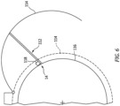
FIG. 6 is a partial schematic illustration of the aircraft assembly with a hold open rod arranged with a cowl. -
FIG. 1 illustrates anassembly 10 for an aircraft such as, but not limited to, a commercial airliner or cargo plane. Thisaircraft assembly 10 includes a positive locking hand (e.g., manual)actuator 12 and anothercomponent 14 of the aircraft operatively coupled to thehand actuator 12 through a cable assembly 16 (and/or another linkage arrangement). Theaircraft component 14 may be configured as or otherwise include a hold open rod ("HOR") for a nacelle cowl or another type of aircraft door or hatch. Theaircraft component 14 may also or alternatively be configured as or otherwise include a lock for still another component of the aircraft; e.g., the hold open rod, the nacelle cowl or another type of aircraft door or hatch. The present disclosure, however, is not limited to the foregoing exemplary aircraft component configurations. Theaircraft component 14, for example, may be configured as or otherwise include any device (or devices) which may be actuated or otherwise moved utilizing thehand actuator 12; e.g., thehand actuator 12 may be or may be coupled to an opening mechanism for an aircraft door or hatch. Thehand actuator 12 ofFIG. 1 includes asupport structure 18, ahandle structure 20 and a positivelocking guide system 22. - The
support structure 18 extends longitudinally between and to a longitudinalfirst end 24 of thesupport structure 18 and a longitudinalsecond end 26 of thesupport structure 18. Thesupport structure 18 extends vertically between and to alower side 28 of thesupport structure 18 and an upper side 30 of thesupport structure 18. Note, the terms "lower" and "upper" may be used herein to describe an orientation of thehand actuator 12 and its various components with respect to the arrangement shown inFIG. 1 . The terms "lower" and "upper", however, are not intended to limit the orientation of thehand actuator 12 and its various components to any specific orientation relative to gravity. Thesupport structure 18 ofFIG. 1 includes a mountingbase 32, one ormore walls handle mount 36 and acable mount 38. - The mounting
base 32 is disposed at (e.g., on, adjacent or proximate) the support structurelower side 28. This mountingbase 32 is configured to provide a platform for mounting thehand actuator 12 to a (e.g., stationary) structure of the aircraft. The mountingbase 32 ofFIG. 1 extends longitudinally from the support structure first end 24 (e.g., towards the support structure second end 26) to asecond end 40 of the mountingbase 32, which mounting basesecond end 40 ofFIG. 1 is longitudinally spaced (e.g., recessed) inward from the support structuresecond end 26. However, in other embodiments, it is contemplated the mounting basesecond end 40 may alternatively be located at the support structuresecond end 26. - Each of the walls 34 is connected to (e.g., formed integral with or otherwise attached to) and may be perpendicular to the mounting
base 32. Each of the walls 34 projects vertically out from the mountingbase 32 to a respective distal end 42 of that wall 34, which wall end 42 is disposed at the support structure upper side 30. Each of the walls 34 ofFIG. 1 extends longitudinally from the support structure first end 24 (e.g., towards the support structure second end 26) to the mounting basesecond end 40. The walls 34 are laterally spaced apart from one another thereby forming achannel 44 in thesupport structure 18. Thischannel 44 extends longitudinally along each of the walls 34. Thechannel 44 extends laterally within thesupport structure 18 between the walls 34. Thechannel 44 ofFIG. 1 extends vertically into thesupport structure 18 from the support structure upper side 30 to the mountingbase 32; see alsoFIG. 2 . - Each wall 34 may include a
wall plate 46 and awall frame 48 connected (e.g., mounted) to thewall plate 46. Thewall frame 48 may provide a structural backbone and/or otherwise structurally reinforce thewall plate 46. Thewall frame 48 ofFIG. 1 also provides the respective wall 34 with a track 50. The track 50 ofFIG. 1 is configured as a slot 52. This slot 52 extends longitudinally within the wall 34 and itsrespective wall frame 48 between opposing longitudinal ends of the slot 52. The slot 52 extends vertically within the wall 34 and itsrespective wall frame 48 between opposing vertical side of the slot 52. The slot 52 extends laterally through the wall 34 and itsrespective wall frame 48 to thechannel 44. - The
wall frame 48 ofFIG. 1 includes atrack section 54, alower wall mount 56 and anupper wall mount 58. Thetrack section 54 forms the respective track 50 and its slot 52. Thelower wall mount 56 ofFIG. 1 is configured as a finger (e.g., a rib) which projects vertically (e.g., downward) out from thetrack section 54 towards the support structurelower side 28. The upper wall mount 58 ofFIG. 1 is configured as a finger (e.g., a rib) which projects vertically (e.g., upward) out from thetrack section 54 towards the support structure upper side 30. - The
handle mount 36 is disposed at the support structurefirst end 24. Thehandle mount 36 may be vertically aligned with thetrack section 54 of eachwall frame 48. Thehandle mount 36 ofFIG. 1 is configured as a mounting bracket which is connected to (e.g., formed integral with or otherwise attached to) and extends laterally between the walls 34 and theirwall plates 46. Referring toFIG. 2 , thehandle mount 36 includes ahandle aperture 60. Thishandle aperture 60 extends longitudinally through thehandle mount 36 to thechannel 44. Thehandle aperture 60 ofFIG. 2 extends vertically and laterally within thehandle mount 36. - Referring to
FIG. 1 , thecable mount 38 is disposed at the support structuresecond end 26. Thecable mount 38 may be vertically aligned with thetrack section 54 of eachwall frame 48. Thecable mount 38 ofFIG. 1 is configured as a mounting bracket which is connected to (e.g., formed integral with or otherwise attached to) and extends laterally between the walls 34 and theirwall plates 46. Thecable mount 38 ofFIG. 1 also projects longitudinally out from the walls 34 to the support structuresecond end 26. Referring toFIG. 2 , thecable mount 38 includes acable aperture 62. Thiscable aperture 62 extends longitudinally through thecable mount 38 to thechannel 44. Thecable aperture 62 ofFIG. 2 has a circular cross-sectional geometry. - The
handle structure 20 ofFIG. 2 extends longitudinally along alongitudinal centerline 64 of thehandle structure 20 between and to a longitudinalfirst end 66 of thehandle structure 20 and a longitudinal second end 68 of thehandle structure 20. Thehandle structure 20 ofFIG. 2 includes a handle 70 (e.g., a hand grip) and astrut 72. Thehandle 70 is disposed at the handle structurefirst end 66. Thestrut 72 is connected to (e.g., formed integral with or otherwise attached to) and may be perpendicular to thehandle 70. Thestrut 72 projects longitudinally out from thehandle 70 to a distal end 74 of thestrut 72, which strut end 74 is disposed at the handle structure second end 68. - The
handle structure 20 is mated with thesupport structure 18 and itshandle mount 36. Thestrut 72 ofFIG. 2 , for example, is received by thehandle aperture 60. More particularly, thestrut 72 projects longitudinally out from thehandle 70, through thehandle aperture 60, and into thechannel 44. Thehandle 70 is thereby disposed outside of thesupport structure 18 towards the support structurefirst end 24. The strut end 74 is disposed within thesupport structure 18 and itschannel 44. Thehandle structure 20 and itsstrut 72 are also arranged laterally between the walls 34; see alsoFIG. 1 . - The
guide system 22 is configured to guide longitudinal movement of thehandle structure 20 along / relative to thesupport structure 18 between a first position (seeFIG. 3 ) and a second position (seeFIG. 4 ). Theguide system 22 ofFIG. 2 , for example, includes the tracks 50 and one or more slides 76 (one visible in figures; see alsoFIG. 1 ). Here, the slides 76 are configured as part of a coupling pin 78. Theguide system 22 ofFIG. 2 also includes a plurality ofguide elements - Each of the
guide elements centerline FIG. 2 includes a spring element 84 (e.g., a coil spring), a first end fitting 86 and a second end fitting 88. Thespring element 84 is disposed between the first end fitting 86 and the second end fitting 88 along the respective guide element centerline 82. Thespring element 84 is also attached to the first end fitting 86 and the second end fitting 88. The first end fitting 86 is disposed at the first end of the respective guide element 80. The second end fitting 88 is disposed at the second end of the respective guide element 80. - The
upper guide elements 80A are arranged substantially vertically above thehandle structure 20, and on opposing lateral sides of thehandle structure 20. Thelower guide elements 80B are arranged substantially vertically below thehandle structure 20, and on opposing lateral sides of thehandle structure 20. Here, the first end fitting 86 of eachupper guide element 80A is disposed laterally between the first end fitting 86 of a respective (e.g., laterally neighboring)lower guide element 80B and thestrut 72. The coupling pin 78 pivotally couples each guide element 80 as well as ayoke 90 of thecable assembly 16 to thehandle structure 20 and itsstrut 72. The coupling pin 78 ofFIG. 2 , for example, may extend sequentially through the first end fitting 86 of oneupper guide element 80A, a first arm of theyoke 90, the first end fitting 86 of onelower guide element 80B, thestrut 72, the first end fitting 86 of the otherlower guide element 80B, a second arm of theyoke 90 and the first end fitting 86 of the otherupper guide element 80A between the slides 76. With this arrangement, each of theactuator members 80 and 90 is pivotally coupled to thehandle structure 20 and itsstrut 72 at a common handlestructure pivot axis 92, which handlestructure pivot axis 92 is perpendicular to and may be coincident with thelongitudinal centerline 64. Each of the slides 76 is mated with a respective one of the tracks 50 and its slot 52 (see alsoFIG. 1 ). The slides 76 may thereby guide movement of thehandle structure 20 at its second end 68 longitudinally along the tracks 50. - The second end fitting 88 of each
upper guide element 80A is pivotally coupled to a respective wall 34 at a respective upper supportstructure pivot axis 94. The second end fitting 88 of eachupper guide element 80A, for example, may be pinned to a respective one of the upper wall mounts 58 (see alsoFIG. 1 ). Here, the upper support structure pivot axes 94 are coaxial. Each upper supportstructure pivot axis 94 is also vertically offset (e.g., in a vertical upward direction towards the support structure upper side 30) from the handlestructure pivot axis 92 and the tracks 50. Similarly, the second end fitting 88 of eachlower guide element 80B is pivotally coupled to a respective wall 34 at a respective lower supportstructure pivot axis 96. The second end fitting 88 of eachlower guide element 80B, for example, may be pinned to a respective one of the lower wall mounts 56 (see alsoFIG. 1 ). Here, the lower support structure pivot axes 96 are coaxial. Each lower supportstructure pivot axis 96 is also vertically offset (e.g., in a vertical downward direction towards the support structure lower side 28) from the handlestructure pivot axis 92 and the tracks 50. Each lower supportstructure pivot axis 96 may also be longitudinally aligned with each upper supportstructure pivot axis 94 along thelongitudinal centerline 64. With this arrangement, thelower guide elements 80B may substantially mirror theupper guide elements 80A about thehandle structure 20 and itsstrut 72. Moreover, each guide element 80 also flexibly couples thehandle structure 20 at its second end 68 to thesupport structure 18 and its respective wall 34. - The
cable assembly 16 ofFIG. 2 includes acable 98, asleeve 100 and theyoke 90. Thecable 98 projects longitudinally out of thesleeve 100 to a distal end of thecable 98. Thecable 98 is connected to theyoke 90 at its distal end. Thiscable 98 is operable to move (e.g., slide) within thesleeve 100. By contrast, thesleeve 100 is mounted (e.g., fixedly attached) to thecable mount 38. A fitting 102, for example, secures (e.g., longitudinally anchors) thesleeve 100 to thecable mount 38, and thecable 98 projects through thecable mount 38, out of thesleeve 100 and longitudinally into thechannel 44 to theyoke 90. Theyoke 90 pivotally couples thecable 98 to thehandle structure 20 about the handlestructure pivot axis 92. - With the foregoing arrangement, the guide elements 80 are operable to bias and substantially maintain the handle
structure pivot axis 92 at a vertical intermediate (e.g., centered) position between the upper and the lower support structure pivot axes 94 and 96. Each of thespring elements 84, for example, may be maintained in some degree of compression and push the handlestructure pivot axis 92 to the vertical intermediate position; e.g., at various longitudinal slide positions along the tracks 50. Each slide 76 therefore may subject the respective track 50 to very little if any vertical loads as thehandle structure 20 is longitudinally moved between the first position (seeFIG. 3 ) and the second position (seeFIG. 4 ). By reducing vertical loads between the slides 76 and the tracks 50, theguide system 22 may reduce wear to the slides 76 and/or the tracks 50 which may otherwise occur. Moreover, thespring elements 84 may bias thehandle structure 20 to each of the first and the second positions. Thespring elements 84 may thereby positively lock thehand actuator 12 in the first or the second position. - As the
handle structure 20 is pulled from the first position ofFIG. 3 to the second position ofFIG. 4 , thehandle structure 20 pulls thecable 98 and may thereby actuate a first operation of theaircraft component 14. As thehandle structure 20 is pushed from the second position ofFIG. 4 to the first position ofFIG. 3 , thehandle structure 20 pushes thecable 98 and may thereby actuate a second (e.g., opposite, reverser, etc.) operation of theaircraft component 14. - Referring to
FIG. 5 , moving between the first position (see solid line guide elements 80; see alsoFIG. 3 ) and the second position (see left dashed line guide elements 80; see alsoFIG. 4 ), eachupper guide element 80A pivots a first number ofdegrees 104 about the handlestructure pivot axis 92 / about the upper supportstructure pivot axis 94. This first number ofdegrees 104 may be between seventy degrees (70°) and one-hundred and ten degrees (110°); e.g., between eighty degrees (80°) and one-hundred degrees (100°). Similarly, eachlower guide element 80B pivots a second number ofdegrees 106 about the handlestructure pivot axis 92 / about the lower supportstructure pivot axis 96. This second number ofdegrees 106 may be between seventy degrees (70°) and one-hundred and ten degrees (110°); e.g., between eighty degrees (80°) and one-hundred degrees (100°). The second number ofdegrees 106 may also be equal to and congruent with the first number ofdegrees 104. - When the
handle structure 20 is in the first position (see alsoFIG. 3 ), thecenterline 82A of eachupper guide element 80A is angularly offset from thecenterline 82B of eachlower guide element 80B by an included (non-zero)first position angle 108. Thisfirst position angle 108 may be between seventy degrees (70°) and one-hundred and ten degrees (110°); e.g., between eighty degrees (80°) and one-hundred degrees (100°). Moreover, thelongitudinal centerline 64 may be angularly centered between thecenterlines - When the
handle structure 20 is in the second position (see alsoFIG. 4 ), thecenterline 82A of eachupper guide element 80A is angularly offset from thecenterline 82B of eachlower guide element 80B by an included (non-zero)second position angle 110. Thissecond position angle 110 may be between seventy degrees (70°) and one-hundred and ten degrees (110°); e.g., between eighty degrees (80°) and one-hundred degrees (100°). Thesecond position angle 110 may also be equal to and congruent with thefirst position angle 108. Moreover, thelongitudinal centerline 64 may be angularly centered between thecenterlines - When the
handle structure 20 is in an intermediate (e.g., mid, centered, etc.) position (see center dashed line guide elements 80) longitudinally between the first position and the second position, thecenterline 82A of eachupper guide element 80A may be parallel with thecenterline 82B of eachlower guide element 80B. Each centerline 82 may thereby be perpendicular to thelongitudinal centerline 64. Note, this intermediate position may be a kinematically unstable (e.g., resting) position where thespring elements 84 may have a tendency to push thehandle structure 20 longitudinally to the first position (see alsoFIG. 3 ) or the first position (see alsoFIG. 4 ), where the first and the second positions may be kinematically stable (e.g., resting) positions. -
FIG. 6 illustrates theaircraft component 14 as (or part of) a holdopen rod 112 for afan cowl 114. Thefan cowl 114 ofFIG. 6 is configured to move (e.g., pivot) between a closed position (see dashed line) and an open position (see solid line). When thefan cowl 114 is in the closed position, thefan cowl 114 provides an aerodynamic cover over afan case 116 of a gas turbine engine. When thefan cowl 114 is in the open position, access is provided to thefan case 116 and components arranged with (e.g., mounted to) thefan case 116. In this open position, the holdopen rod 112 is configured to hold open thefan cowl 114. Here, the holdopen rod 112, in general, or aposition lock 118 for the holdopen rod 112 may be configured as theaircraft component 14 actuated by thehand actuator 12 ofFIG. 1 . The present disclosure, however, is not limited to such an arrangement. The holdopen rod 112, for example, may alternatively hold a thrust reverser section or any other door or hatch in its open position. Furthermore, as discussed above, theaircraft component 14 is not limited to hold open rod or lock applications. - While various embodiments of the present invention have been disclosed, it will be apparent to those of ordinary skill in the art that many more embodiments and implementations are possible within the scope of the invention. For example, the present invention as described herein includes several aspects and embodiments that include particular features. Although these features may be described individually, it is within the scope of the present invention that some or all of these features may be combined with any one of the aspects and remain within the scope of the invention. Accordingly, the present invention is not to be restricted except in light of the attached claims and their equivalents.
Claims (15)
- An assembly (10) for an aircraft, comprising:an actuator (12) including a support structure (18), a handle structure (20) and a guide system (22) configured to guide movement of the handle structure (20) longitudinally along the support structure (18) between a first position and a second position, the guide system (22) including a first guide element (80A) and a second guide element (80B), the first guide element (80A) comprising a first spring element (84) and pivotally coupled to the handle structure (20) at a handle structure pivot axis (92), and the second guide element (80B) comprising a second spring element (84) and pivotally coupled to the handle structure (20) at the handle structure pivot axis (92); anda cable assembly (16) including a sleeve (100) and a cable (98) projecting longitudinally out of the sleeve (100), the sleeve (100) attached to the support structure (18), and the cable (98) coupled to the handle structure (20).
- The assembly (10) of claim 1, wherein the first guide element (80A) and the second guide element (80B) are disposed to opposing sides of the handle structure (20).
- The assembly (10) of claim 1 or 2, whereinthe support structure (18) comprises a wall (34);the first guide element (80A) is pivotally coupled to the wall (34) at a first support structure pivot axis (94); andthe second guide element (80B) is pivotally coupled to the wall (34) at a second support structure pivot axis (96) which is offset from the first support structure pivot axis (94), optionally wherein the second support structure pivot axis (96) is longitudinally aligned with the first support structure pivot axis (94).
- The assembly (10) of claim 3, whereinthe wall (34) is a first wall (34A), and the support structure (18) further comprises a second wall (34B);the handle structure (20) is disposed laterally between the first wall (34A) and the second wall (34B);the guide system (22) further includes a third guide element (80C) and a fourth guide element (80D);the third guide element (80C) comprises a third spring element (84), the third guide element (80C) is pivotally coupled to the handle structure (20) at the handle structure pivot axis (92), and the third guide element (80C) is pivotally coupled to the second wall (34B) at a third support structure pivot axis; andthe fourth guide element (80D) comprises a fourth spring element (84), the fourth guide element (80D) is pivotally coupled to the handle structure (20) at the handle structure pivot axis (92), and the fourth guide element (80D) is pivotally coupled to the second wall (34B) at a fourth support structure pivot axis which is offset from the third support structure pivot axis, optionally whereinthe third support structure (18) pivot axis is coaxial with the first support structure pivot axis (94) and the fourth support structure (18) pivot axis is coaxial with the second support structure pivot axis (96).
- The assembly (10) of any preceding claim, wherein at least one ofthe first guide element (80A) pivots between seventy degrees and one-hundred and ten degrees about the handle structure pivot axis (92) as the handle structure (20) moves longitudinally from the first position to the second position; orthe second guide element (80B) pivots between seventy degrees and one-hundred and ten degrees about the handle structure pivot axis (92) as the handle structure (20) moves longitudinally from the first position to the second position.
- The assembly (10) of any preceding claim, whereinthe first guide element (80A) has a first guide element centerline (82A), and the first guide element (80A) extends along the first guide element centerline (82A) to the handle structure pivot axis (92);the second guide element (80B) has a second guide element centerline (82B), and the second guide element (80B) extends along the second guide element centerline (82B) to the handle structure pivot axis (92); andthe first guide element centerline (82A) is angularly offset from the second guide element centerline (82B) by a first position angle (108) when the handle structure (20) is in the first position.
- The assembly (10) of claim 6, wherein the first guide element centerline (82A) is angularly offset from the second guide element centerline (82B) by a second position angle (110) when the handle structure (20) is in the second position, optionally wherein the second position angle (110) is equal to the first position angle (108).
- The assembly (10) of claim 6 or 7, wherein the first guide element centerline (82A) is parallel with the second guide element centerline (82B) when the handle structure (20) is in an intermediate position longitudinally between the first position and the second position.
- The assembly (10) of any preceding claim, wherein at least one ofthe first spring element (84) comprises a first coil spring; orthe second spring element (84) comprises a second coil spring.
- The assembly (10) of any preceding claim, wherein at least one ofthe first spring element (84) and the second spring element (84) are each compressed when the handle structure (20) is in the first position; orthe first spring element (84) and the second spring element (84) are each compressed when the handle structure (20) is in the second position.
- The assembly (10) of any preceding claim, whereinthe guide system (22) further includes a track (50) and a slide (76) configured to move longitudinally along the track (50);the track (50) configured with the support structure (18); andthe slide (76) configured with the handle structure (20), optionally wherein the handle structure pivot axis (92) is a centerline axis of the slide (76).
- The assembly (10) of any preceding claim, whereinthe support structure (18) comprises a handle mount (36);the handle structure (20) includes a handle (70) and a strut (72), the strut (72) projects longitudinally out from the handle (70) and through an aperture in the handle mount (36); andthe first guide element (80A), the second guide element (80B) and the cable (98) are coupled to the strut (72).
- The assembly (10) of any preceding claim, further comprising:a cowl (114) configured to pivot between a closed position and an open position and a hold open rod (112) configured to hold the cowl (114) in the open position, the actuator (12) operatively coupled to the hold open rod (112) through the cable (98); and/ora lock (118) operatively coupled to and actuatable by the actuator (12) through the cable (98).
- An assembly (10) for an aircraft, comprising:a support structure (18) including a handle mount (36) and a track (50);a handle structure (20) projecting longitudinally through an aperture in the handle mount (36);a slide (76) coupled to the handle structure (20) and mated with the track (50), the slide (76) configured to move longitudinally along the track (50);a first guide element (80A) pivotally coupled to the handle structure (20) at a handle structure pivot axis (92), the first guide element (80A) pivotally coupled to the support structure (18) at a first support structure pivot axis (94), and the first guide element (80A) comprising a first spring element (84); anda second guide element (80B) pivotally coupled to the handle structure (20) at the handle structure pivot axis (92), the second guide element (80B) pivotally coupled to the support structure (18) at a second support structure pivot axis (96) which is offset from the first support structure pivot axis (94), and the second guide element (80B) comprising a second spring element (84).
- An assembly (10) for an aircraft, comprising:a support structure (18) including a first wall (34a), a second wall (34b) and a channel (44) laterally between the first wall (34a) and the second wall (34b);a handle structure (20) projecting longitudinally into the channel (44); anda plurality of guide elements pivotally coupled to the handle structure (20) at a handle structure pivot axis (92), each of the plurality of guide elements comprising a spring element (84), and the plurality of guide elements including a first lower guide element (80B), a second lower guide element (80B), a first upper guide element (80A) and a second upper guide element (80A);the first lower guide element (80B) pivotally coupled to the first wall (34a) at a lower support structure pivot axis (96), and the second lower guide element (80B) pivotally coupled to the second wall (34b) at the lower support structure pivot axis (96); andthe first upper guide element (80A) pivotally coupled to the first wall (34a) at an upper support structure pivot axis (94), and the second upper guide element (80A) pivotally coupled to the second wall (34b) at the upper support structure pivot axis (94).
Applications Claiming Priority (1)
| Application Number | Priority Date | Filing Date | Title |
|---|---|---|---|
| US18/208,063 US12085973B1 (en) | 2023-06-09 | 2023-06-09 | Spring guided hand actuator for aircraft component |
Publications (1)
| Publication Number | Publication Date |
|---|---|
| EP4474269A1 true EP4474269A1 (en) | 2024-12-11 |
Family
ID=91469818
Family Applications (1)
| Application Number | Title | Priority Date | Filing Date |
|---|---|---|---|
| EP24181186.8A Pending EP4474269A1 (en) | 2023-06-09 | 2024-06-10 | Spring guided hand actuator for aircraft component |
Country Status (2)
| Country | Link |
|---|---|
| US (1) | US12085973B1 (en) |
| EP (1) | EP4474269A1 (en) |
Citations (2)
| Publication number | Priority date | Publication date | Assignee | Title |
|---|---|---|---|---|
| US20100037724A1 (en) * | 2008-08-18 | 2010-02-18 | Shimano Inc. | Cable operating mechanism |
| US20200018096A1 (en) * | 2018-07-11 | 2020-01-16 | MarathonNorco Aerospace | Cable Release System for a Hold Open Rod Mechanism |
Family Cites Families (6)
| Publication number | Priority date | Publication date | Assignee | Title |
|---|---|---|---|---|
| US5836564A (en) | 1996-05-23 | 1998-11-17 | Avibank Mfg., Inc | Fail safe hold open telescoping rod |
| US6189832B1 (en) | 1998-04-03 | 2001-02-20 | Hartwell Corporation | Permanently connected remote latch mechanism |
| US6629712B2 (en) | 2001-03-30 | 2003-10-07 | Hartwell Corporation | Extendable latch |
| DE102015202875A1 (en) * | 2014-03-14 | 2015-09-17 | Schaeffler Technologies AG & Co. KG | Pedal power generation device |
| DE102015214974A1 (en) * | 2015-08-06 | 2017-02-09 | Schaeffler Technologies AG & Co. KG | Device for power simulation on an actuating element of a vehicle |
| US10906661B2 (en) * | 2018-11-05 | 2021-02-02 | Rohr, Inc. | Nacelle cowl hinge |
-
2023
- 2023-06-09 US US18/208,063 patent/US12085973B1/en active Active
-
2024
- 2024-06-10 EP EP24181186.8A patent/EP4474269A1/en active Pending
Patent Citations (2)
| Publication number | Priority date | Publication date | Assignee | Title |
|---|---|---|---|---|
| US20100037724A1 (en) * | 2008-08-18 | 2010-02-18 | Shimano Inc. | Cable operating mechanism |
| US20200018096A1 (en) * | 2018-07-11 | 2020-01-16 | MarathonNorco Aerospace | Cable Release System for a Hold Open Rod Mechanism |
Also Published As
| Publication number | Publication date |
|---|---|
| US12085973B1 (en) | 2024-09-10 |
Similar Documents
| Publication | Publication Date | Title |
|---|---|---|
| EP3587244B1 (en) | Slide and rotating cockpit door and method | |
| EP3774526B1 (en) | Door assembly comprising hinge with two pins | |
| US7275362B2 (en) | Thrust reversers including latching mechanisms and methods for manufacturing such thrust reversers | |
| US6629712B2 (en) | Extendable latch | |
| US20210332624A1 (en) | Door translation hinge assembly | |
| US5864922A (en) | Self centering hinge | |
| US12085973B1 (en) | Spring guided hand actuator for aircraft component | |
| US12110109B2 (en) | Device for accommodating and for releasing a payload on an aerial vehicle | |
| EP0182392B1 (en) | Releasable hinge | |
| US11072433B2 (en) | Aircraft cowl locking system | |
| US12326021B2 (en) | Hook latch for aircraft panel | |
| US12345075B2 (en) | Furniture assembly and interlock kit thereof | |
| US12478179B2 (en) | Sliding rail | |
| US5068946A (en) | Locking hinge assembly for an aircraft cowling | |
| US11643848B2 (en) | Aircraft panel system, aircraft, and method of operating the aircraft panel system | |
| EP4467463A2 (en) | Long throw latch for aircraft system | |
| US11834883B2 (en) | Actuating arm drive with spring guide | |
| US12049854B2 (en) | Turbofan having mobile deflectors and a system for actuating the deflectors | |
| EP4428355A2 (en) | Thrust reverser with lost motion device | |
| EP1764499A1 (en) | Thrust reverser including a latching mechanism and method of manufacturing such a thrust reverser | |
| JP2025525659A (en) | valve | |
| EP4474287A1 (en) | Long throw latch for aircraft system | |
| US11591189B2 (en) | Coupling device between an elevator car door and a landing door and elevator system | |
| CN116591567A (en) | Carbon ceramic hatch hinge mechanism | |
| US11773806B2 (en) | Assembly for an aircraft propulsion system comprising a hinged structure supporting the fan cowl and the thrust reverser |
Legal Events
| Date | Code | Title | Description |
|---|---|---|---|
| PUAI | Public reference made under article 153(3) epc to a published international application that has entered the european phase |
Free format text: ORIGINAL CODE: 0009012 |
|
| STAA | Information on the status of an ep patent application or granted ep patent |
Free format text: STATUS: THE APPLICATION HAS BEEN PUBLISHED |
|
| AK | Designated contracting states |
Kind code of ref document: A1 Designated state(s): AL AT BE BG CH CY CZ DE DK EE ES FI FR GB GR HR HU IE IS IT LI LT LU LV MC ME MK MT NL NO PL PT RO RS SE SI SK SM TR |
|
| STAA | Information on the status of an ep patent application or granted ep patent |
Free format text: STATUS: REQUEST FOR EXAMINATION WAS MADE |
|
| 17P | Request for examination filed |
Effective date: 20250611 |
|
| GRAP | Despatch of communication of intention to grant a patent |
Free format text: ORIGINAL CODE: EPIDOSNIGR1 |
|
| STAA | Information on the status of an ep patent application or granted ep patent |
Free format text: STATUS: GRANT OF PATENT IS INTENDED |
|
| INTG | Intention to grant announced |
Effective date: 20260121 |
|
| GRAS | Grant fee paid |
Free format text: ORIGINAL CODE: EPIDOSNIGR3 |