EP4474259A1 - Easy loading and unloading structure, battery mounting frame, vehicle frame assembly, and electric vehicle - Google Patents
Easy loading and unloading structure, battery mounting frame, vehicle frame assembly, and electric vehicle Download PDFInfo
- Publication number
- EP4474259A1 EP4474259A1 EP24178749.8A EP24178749A EP4474259A1 EP 4474259 A1 EP4474259 A1 EP 4474259A1 EP 24178749 A EP24178749 A EP 24178749A EP 4474259 A1 EP4474259 A1 EP 4474259A1
- Authority
- EP
- European Patent Office
- Prior art keywords
- bracket
- fixing bracket
- rotatable
- fixing
- battery
- Prior art date
- Legal status (The legal status is an assumption and is not a legal conclusion. Google has not performed a legal analysis and makes no representation as to the accuracy of the status listed.)
- Granted
Links
Images


Classifications
-
- B—PERFORMING OPERATIONS; TRANSPORTING
- B62—LAND VEHICLES FOR TRAVELLING OTHERWISE THAN ON RAILS
- B62J—CYCLE SADDLES OR SEATS; AUXILIARY DEVICES OR ACCESSORIES SPECIALLY ADAPTED TO CYCLES AND NOT OTHERWISE PROVIDED FOR, e.g. ARTICLE CARRIERS OR CYCLE PROTECTORS
- B62J43/00—Arrangements of batteries
- B62J43/10—Arrangements of batteries for propulsion
-
- B—PERFORMING OPERATIONS; TRANSPORTING
- B60—VEHICLES IN GENERAL
- B60K—ARRANGEMENT OR MOUNTING OF PROPULSION UNITS OR OF TRANSMISSIONS IN VEHICLES; ARRANGEMENT OR MOUNTING OF PLURAL DIVERSE PRIME-MOVERS IN VEHICLES; AUXILIARY DRIVES FOR VEHICLES; INSTRUMENTATION OR DASHBOARDS FOR VEHICLES; ARRANGEMENTS IN CONNECTION WITH COOLING, AIR INTAKE, GAS EXHAUST OR FUEL SUPPLY OF PROPULSION UNITS IN VEHICLES
- B60K1/00—Arrangement or mounting of electrical propulsion units
- B60K1/04—Arrangement or mounting of electrical propulsion units of the electric storage means for propulsion
-
- B—PERFORMING OPERATIONS; TRANSPORTING
- B60—VEHICLES IN GENERAL
- B60L—PROPULSION OF ELECTRICALLY-PROPELLED VEHICLES; SUPPLYING ELECTRIC POWER FOR AUXILIARY EQUIPMENT OF ELECTRICALLY-PROPELLED VEHICLES; ELECTRODYNAMIC BRAKE SYSTEMS FOR VEHICLES IN GENERAL; MAGNETIC SUSPENSION OR LEVITATION FOR VEHICLES; MONITORING OPERATING VARIABLES OF ELECTRICALLY-PROPELLED VEHICLES; ELECTRIC SAFETY DEVICES FOR ELECTRICALLY-PROPELLED VEHICLES
- B60L50/00—Electric propulsion with power supplied within the vehicle
- B60L50/50—Electric propulsion with power supplied within the vehicle using propulsion power supplied by batteries or fuel cells
- B60L50/60—Electric propulsion with power supplied within the vehicle using propulsion power supplied by batteries or fuel cells using power supplied by batteries
- B60L50/66—Arrangements of batteries
-
- B—PERFORMING OPERATIONS; TRANSPORTING
- B60—VEHICLES IN GENERAL
- B60L—PROPULSION OF ELECTRICALLY-PROPELLED VEHICLES; SUPPLYING ELECTRIC POWER FOR AUXILIARY EQUIPMENT OF ELECTRICALLY-PROPELLED VEHICLES; ELECTRODYNAMIC BRAKE SYSTEMS FOR VEHICLES IN GENERAL; MAGNETIC SUSPENSION OR LEVITATION FOR VEHICLES; MONITORING OPERATING VARIABLES OF ELECTRICALLY-PROPELLED VEHICLES; ELECTRIC SAFETY DEVICES FOR ELECTRICALLY-PROPELLED VEHICLES
- B60L53/00—Methods of charging batteries, specially adapted for electric vehicles; Charging stations or on-board charging equipment therefor; Exchange of energy storage elements in electric vehicles
- B60L53/80—Exchanging energy storage elements, e.g. removable batteries
-
- B—PERFORMING OPERATIONS; TRANSPORTING
- B62—LAND VEHICLES FOR TRAVELLING OTHERWISE THAN ON RAILS
- B62J—CYCLE SADDLES OR SEATS; AUXILIARY DEVICES OR ACCESSORIES SPECIALLY ADAPTED TO CYCLES AND NOT OTHERWISE PROVIDED FOR, e.g. ARTICLE CARRIERS OR CYCLE PROTECTORS
- B62J43/00—Arrangements of batteries
- B62J43/10—Arrangements of batteries for propulsion
- B62J43/13—Arrangements of batteries for propulsion on rider-propelled cycles with additional electric propulsion
-
- B—PERFORMING OPERATIONS; TRANSPORTING
- B62—LAND VEHICLES FOR TRAVELLING OTHERWISE THAN ON RAILS
- B62J—CYCLE SADDLES OR SEATS; AUXILIARY DEVICES OR ACCESSORIES SPECIALLY ADAPTED TO CYCLES AND NOT OTHERWISE PROVIDED FOR, e.g. ARTICLE CARRIERS OR CYCLE PROTECTORS
- B62J43/00—Arrangements of batteries
- B62J43/10—Arrangements of batteries for propulsion
- B62J43/16—Arrangements of batteries for propulsion on motorcycles or the like
-
- B—PERFORMING OPERATIONS; TRANSPORTING
- B62—LAND VEHICLES FOR TRAVELLING OTHERWISE THAN ON RAILS
- B62J—CYCLE SADDLES OR SEATS; AUXILIARY DEVICES OR ACCESSORIES SPECIALLY ADAPTED TO CYCLES AND NOT OTHERWISE PROVIDED FOR, e.g. ARTICLE CARRIERS OR CYCLE PROTECTORS
- B62J43/00—Arrangements of batteries
- B62J43/20—Arrangements of batteries characterised by the mounting
- B62J43/23—Arrangements of batteries characterised by the mounting dismounted when charging
-
- B—PERFORMING OPERATIONS; TRANSPORTING
- B62—LAND VEHICLES FOR TRAVELLING OTHERWISE THAN ON RAILS
- B62J—CYCLE SADDLES OR SEATS; AUXILIARY DEVICES OR ACCESSORIES SPECIALLY ADAPTED TO CYCLES AND NOT OTHERWISE PROVIDED FOR, e.g. ARTICLE CARRIERS OR CYCLE PROTECTORS
- B62J43/00—Arrangements of batteries
- B62J43/20—Arrangements of batteries characterised by the mounting
- B62J43/28—Arrangements of batteries characterised by the mounting hidden within the cycle frame
-
- B—PERFORMING OPERATIONS; TRANSPORTING
- B62—LAND VEHICLES FOR TRAVELLING OTHERWISE THAN ON RAILS
- B62K—CYCLES; CYCLE FRAMES; CYCLE STEERING DEVICES; RIDER-OPERATED TERMINAL CONTROLS SPECIALLY ADAPTED FOR CYCLES; CYCLE AXLE SUSPENSIONS; CYCLE SIDECARS, FORECARS, OR THE LIKE
- B62K19/00—Cycle frames
- B62K19/30—Frame parts shaped to receive other cycle parts or accessories
-
- B—PERFORMING OPERATIONS; TRANSPORTING
- B62—LAND VEHICLES FOR TRAVELLING OTHERWISE THAN ON RAILS
- B62M—RIDER PROPULSION OF WHEELED VEHICLES OR SLEDGES; POWERED PROPULSION OF SLEDGES OR SINGLE-TRACK CYCLES; TRANSMISSIONS SPECIALLY ADAPTED FOR SUCH VEHICLES
- B62M6/00—Rider propulsion of wheeled vehicles with additional source of power, e.g. combustion engine or electric motor
- B62M6/80—Accessories, e.g. power sources; Arrangements thereof
- B62M6/90—Batteries
-
- H—ELECTRICITY
- H01—ELECTRIC ELEMENTS
- H01M—PROCESSES OR MEANS, e.g. BATTERIES, FOR THE DIRECT CONVERSION OF CHEMICAL ENERGY INTO ELECTRICAL ENERGY
- H01M50/00—Constructional details or processes of manufacture of the non-active parts of electrochemical cells other than fuel cells, e.g. hybrid cells
- H01M50/20—Mountings; Secondary casings or frames; Racks, modules or packs; Suspension devices; Shock absorbers; Transport or carrying devices; Holders
- H01M50/244—Secondary casings; Racks; Suspension devices; Carrying devices; Holders characterised by their mounting method
-
- H—ELECTRICITY
- H01—ELECTRIC ELEMENTS
- H01M—PROCESSES OR MEANS, e.g. BATTERIES, FOR THE DIRECT CONVERSION OF CHEMICAL ENERGY INTO ELECTRICAL ENERGY
- H01M50/00—Constructional details or processes of manufacture of the non-active parts of electrochemical cells other than fuel cells, e.g. hybrid cells
- H01M50/20—Mountings; Secondary casings or frames; Racks, modules or packs; Suspension devices; Shock absorbers; Transport or carrying devices; Holders
- H01M50/249—Mountings; Secondary casings or frames; Racks, modules or packs; Suspension devices; Shock absorbers; Transport or carrying devices; Holders specially adapted for aircraft or vehicles, e.g. cars or trains
-
- B—PERFORMING OPERATIONS; TRANSPORTING
- B60—VEHICLES IN GENERAL
- B60K—ARRANGEMENT OR MOUNTING OF PROPULSION UNITS OR OF TRANSMISSIONS IN VEHICLES; ARRANGEMENT OR MOUNTING OF PLURAL DIVERSE PRIME-MOVERS IN VEHICLES; AUXILIARY DRIVES FOR VEHICLES; INSTRUMENTATION OR DASHBOARDS FOR VEHICLES; ARRANGEMENTS IN CONNECTION WITH COOLING, AIR INTAKE, GAS EXHAUST OR FUEL SUPPLY OF PROPULSION UNITS IN VEHICLES
- B60K1/00—Arrangement or mounting of electrical propulsion units
- B60K1/04—Arrangement or mounting of electrical propulsion units of the electric storage means for propulsion
- B60K2001/0455—Removal or replacement of the energy storages
-
- B—PERFORMING OPERATIONS; TRANSPORTING
- B62—LAND VEHICLES FOR TRAVELLING OTHERWISE THAN ON RAILS
- B62J—CYCLE SADDLES OR SEATS; AUXILIARY DEVICES OR ACCESSORIES SPECIALLY ADAPTED TO CYCLES AND NOT OTHERWISE PROVIDED FOR, e.g. ARTICLE CARRIERS OR CYCLE PROTECTORS
- B62J11/00—Supporting arrangements specially adapted for fastening specific devices to cycles, e.g. supports for attaching maps
- B62J11/04—Supporting arrangements specially adapted for fastening specific devices to cycles, e.g. supports for attaching maps for bottles
Definitions
- the present disclosure relates to the technical field of electric vehicles, in particular to an easy loading and unloading structure, a battery mounting frame, a vehicle frame assembly and an electric vehicle.
- a known battery mounting frame is, for example, a rotatable self-locking structure for easy unloading and loading of a battery proposed by CN 202222571600.6 .
- a fixing base is connected to a rotatable base through an equal-height screw so that the rotatable base is rotatable relative to the fixing base, and a rotation angle is limited through a limiting hole and a limiting post.
- a battery holder is connected to the rotatable base, and the fixing base is connected to a vehicle tube. In this way, the battery holder is enabled to be rotated relative to the vehicle tube, which in turn enables the battery to be installed in the middle of the vehicle frame and ensures the easy unloading and loading.
- the present disclosure aims to overcome the defects in the related art, and provides an easy loading and unloading structure, a battery mounting frame, a frame assembly and an electric vehicle, by which the shaking caused during the rotation of the rotatable base relative to the fixing base can be avoided, and good service reliability is enabled.
- An easy loading and unloading structure which includes:
- each of the two auxiliary limiting members is arranged in a corresponding one of the two rotation sliding grooves.
- the easy loading and unloading structure further includes a locking member.
- the fixing bracket is provided with a first connecting hole
- the rotatable bracket is provided with a second connecting hole located between the two rotation sliding grooves, and the second connecting hole is aligned and communicated with the first connecting hole.
- the locking member passes through both the first connecting hole and the second connecting hole in such a manner that the rotatable bracket is rotatably connected with the fixing bracket.
- the auxiliary limiting member includes a rotation guiding post and a mounting member.
- the rotation guiding post protrudes from a side of the fixing bracket close to the rotatable bracket and extends into the rotation sliding groove, and there is relative sliding between the rotation guiding post and the rotation sliding groove when the rotatable bracket is rotated.
- the mounting member is connected to the rotation guiding post. The side of the rotatable bracket away from the fixing bracket is configured to be restrained by the mounting member when the rotatable bracket is rotated relative to the fixing bracket.
- the mounting member is detachably connected to the rotation guiding post.
- the rotation guiding post is provided with a fixing hole
- the mounting member is located in the fixing hole and in thread connection with the rotation guiding post.
- a diameter of an end of the mounting member away from the fixing bracket is greater than a width of the rotation sliding groove.
- a side of the fixing bracket close to the rotatable bracket is provided with a first supporting protrusion and a second supporting protrusion.
- the first supporting protrusion is arranged around the first connecting hole
- the second supporting protrusion is arranged around both the first positioning hole and the second positioning hole.
- the preloading deformation gap is defined between the fixing bracket, the rotatable bracket, the first supporting protrusion and the second supporting protrusion.
- a battery mounting frame which includes a battery holder and the easy loading and unloading structure of any of the embodiments mentioned above.
- the battery holder is mounted on the rotatable bracket, the battery holder is configured to be detachably sleeve on a battery, and the fixing bracket is configured to be connected onto a vehicle frame.
- a vehicle frame assembly which includes a battery, a vehicle frame and a battery mounting frame.
- the vehicle frame is provided with a mounting portion, the fixing bracket is connected onto the mounting portion, and the battery holder is detachably sleeved on the battery.
- An electric vehicle which includes the vehicle frame assembly mentioned above.
- the present disclosure provides an easy loading and unloading structure.
- the easy loading and unloading structure includes a fixing bracket, a rotatable bracket, an elastic positioning post, and an auxiliary limiting member.
- the fixing bracket is provided with a first positioning hole and a second positioning hole.
- the rotatable bracket is rotatably connected to the fixing bracket, and a rotation sliding groove is provided in the rotatable bracket.
- the elastic positioning post is connected to a side of the rotatable bracket facing the fixing bracket, and is arranged to elastically engage with and engage against the first positioning hole or the second positioning hole.
- the auxiliary limiting member is connected to the fixing bracket and extends into the rotation sliding groove. During a process that the rotatable bracket is rotated relative to the fixing bracket, a side of the rotatable bracket away from the fixing bracket is configured to be restrained by the auxiliary limiting member.
- the battery holder may be mounted on the rotatable bracket, and the fixing bracket may be fixed onto the vehicle frame. Since the rotatable bracket is rotatably connected to the fixing bracket, the rotatable bracket can be rotated to a predetermined angle relative to the fixing bracket; as such, when there is a need to unload and load the battery, the user can quickly unload the battery from the battery holder or load the battery into the battery holder.
- the battery is enabled to be quickly unloaded and loaded, especially for a vehicle frame having a relatively narrow space.
- the elastic positioning post is arranged to elastically engage with and engage against the first positioning hole or the second positioning hole, so that the rotatable bracket can be correspondingly positioned at two different positions relative to the fixing bracket, thereby satisfying a positioning requirement for unloading and loading as well as holding the battery.
- the elastic positioning post is elastically engaged with and abuts against the first positioning hole, the rotatable bracket is rotated to a first predetermined position relative to the fixing bracket, in this case, the battery can be unloaded and loaded.
- the elastic positioning post When the elastic positioning post is elastically engaged with and abuts against the second positioning hole, the rotatable bracket is rotated to a second predetermined position relative to the fixing bracket, in this case, the battery is reliably received on the vehicle frame with the easy loading and unloading structure.
- the elastic positioning post When the rotatable bracket is rotated relative to the fixing bracket, the elastic positioning post is arranged to elastically engage with and engage against the first positioning hole or the second positioning hole, so that the elastic positioning post can play a limiting and supporting role at positions where the rotatable bracket is rotated to relative to the fixing bracket.
- the auxiliary limiting member is connected to the fixing bracket and extends into the rotation sliding groove; and when the rotatable bracket is rotated relative to the fixing bracket, a side of the rotatable bracket away from the fixing bracket is configured to be restrained by the auxiliary limiting member; as such, it avoids the rotatable bracket from shaking towards a side away from the fixing bracket during the process that the rotatable bracket is rotated relative to the fixing bracket. This avoids the shaking caused during the rotation of the rotatable base relative to the fixing base in the existing battery mounting frame, improves the reliability of the rotation of the rotatable base relative to the fixing base, and improves the service reliability of the easy loading and unloading structure.
- a vehicle frame assembly 10 is provided in an embodiment of the present disclosure, which may be used in an electric vehicle or other electric devices.
- the electric vehicle may be an electric two-wheeled vehicle or an electric tricycle or an electric four-wheeled vehicle.
- the electric two-wheeled vehicle may be an electric bicycle or an electric motorcycle.
- the vehicle frame assembly 10 includes a battery 100, a vehicle frame 200 and a battery mounting frame 300.
- the vehicle frame 200 is provided with a mounting portion 201, and the battery mounting frame 300 is fixedly mounted to the mounting portion 201.
- the vehicle frame 200 may be a triangular frame 200 or a V-shaped frame 200 or other frames 200.
- the battery mounting frame 300 includes a battery holder 310 and an easy loading and unloading structure 320, and the battery holder 310 is mounted on the easy loading and unloading structure 320.
- the easy loading and unloading structure 320 includes a fixing bracket 321, a rotatable bracket 323, an elastic positioning post 325, and an auxiliary limiting member 327.
- the fixing bracket 321 is configured to be connected to the vehicle frame 200. Specifically, the fixing bracket 321 is connected to the mounting portion 201.
- the fixing bracket 321 is provided thereon with a first positioning hole 3211 and a second positioning hole 3213, and each of the first positioning hole and the second positioning hole may be a blind hole or a recess.
- the rotatable bracket 323 is rotatably connected to the fixing bracket 321, and a rotation sliding groove 3232 is provided in the rotatable bracket 323.
- the battery holder 310 is mounted on the rotatable bracket 323, and the battery holder 310 is detachably sleeved on the battery 100 (that is, the battery 100 is detachably received in the battery bolder 310).
- the battery holder 310 is in a structure formed by over-molding, so that the battery 100 can be quickly removed from or placed into the battery holder 310.
- the elastic positioning post 325 is connected to a side of the rotatable bracket 323 facing the fixing bracket 321, and the elastic positioning post 325 is capable of being elastically engaged with and abutting against the first positioning hole 3211 or the second positioning hole 3213. As illustrated in FIG. 2 and FIG.
- the rotatable bracket 323 when the elastic positioning post 325 is elastically engaged with and abuts against the first positioning hole 3211, the rotatable bracket 323 is rotated to a first predetermined position relative to the fixing bracket 321; in this case, it is rotated to be in an open state, that is, the rotatable bracket 323 is at a predetermined angle relative to the fixing bracket 321, and the battery 100 can be then unloaded and loaded, especially for a vehicle frame 200 having a narrow space. As such, a space required for unloading and loading the battery can be offered by rotating the rotatable bracket out. As illustrated in FIG. 1 and FIG.
- the auxiliary limiting member 327 is connected to the fixing bracket 321 and extends into the rotation sliding groove 3232, and relative sliding happens between the auxiliary limiting member 327 and the rotation sliding groove 3232 when the rotatable bracket 323 is rotated.
- a side of the rotatable bracket 323 away from the fixing bracket 321 is configured to be restrained by the auxiliary limiting member 327, so that the rotatable bracket 323 is prevented, during the process that the rotatable bracket 323 is rotated relative to the fixing bracket 321, from shaking in a direction perpendicular to a plane where the rotatable bracket 323 is rotated.
- the relative sliding between the auxiliary limiting member 327 and the rotation sliding groove 3232 that exists when the rotatable bracket 323 is rotated relative to the fixing bracket 321, improves the smoothness and reliability of the rotation of the rotatable bracket 323 relative to the fixing bracket 321.
- the battery holder 310 may be mounted on the rotatable bracket 323, and the fixing bracket 321 may be fixed on the vehicle frame 200. Since the rotatable bracket 323 is rotatably connected to the fixing bracket 321, the rotatable bracket 323 can be rotated to a predetermined angle relative to the fixing bracket 321; as such, when there is a need to unload and load the battery 100, the user can quickly unload the battery 100 from the battery holder 310 or load the battery 100 onto the battery holder 310. Thus, the battery 100 is enabled to be quickly unloaded and loaded, especially for a vehicle frame 200 having a relatively narrow space.
- the elastic positioning post 325 is arranged to elastically engage with and abut against the first positioning hole 3211 or the second positioning hole 3213, so that the rotatable bracket 323 can be correspondingly positioned at two different positions relative to the fixing bracket 321, thereby satisfying a positioning requirement for unloading and loading as well as holding the battery 100.
- the elastic positioning post 325 is arranged to elastically engage with and abut against the first positioning hole 3211 or the second positioning hole 3213, so that the elastic positioning post 325 can play a limiting and supporting role at positions where the rotatable bracket 323 is rotated to relative to the fixing bracket 321.
- the auxiliary limiting member 327 is connected to the fixing bracket 321 and extends into the rotation sliding groove 3232, and when the rotatable bracket 323 is rotated relative to the fixing bracket 321, a side of the rotatable bracket 323 away from the fixing bracket 321 is configured to be restrained by the auxiliary limiting member 327; as such, it avoids the rotatable bracket 323 from shaking towards a side away from the fixing bracket 321 during the process that the rotatable bracket 323 is rotated relative to the fixing bracket 321.
- the fixing bracket 321 is provided with a first mounting hole 302, and the mounting portion 201 is provided with a first threaded hole 2012.
- the easy loading and unloading structure 320 further includes a first screw rod 322, and the first screw rod 322 passes through both the first mounting hole 302 and the first threaded hole 2012.
- the first screw rod 322 is in thread connection with the vehicle frame 200, so that the fixing bracket 321 is reliably mounted on the vehicle frame 200.
- each of the two auxiliary limiting members 327 is arranged in a corresponding one of the two rotation sliding grooves 3232.
- a second connecting hole 308 is provided between the two rotation sliding grooves 3232.
- the easy loading and unloading structure 320 further includes a locking member 326.
- the fixing bracket 321 is provided with a first connecting hole 306, the rotatable bracket 323 is provided with the second connecting hole 308, and the second connecting hole 308 is aligned and communicated with the first connecting hole 306.
- the locking member 326 passes through both the first connecting hole 306 and the second connecting hole 308, which enables the rotatable bracket 323 to be rotatably connected to the fixing bracket 321.
- the locking member 326 is a screw assembly or a bolt assembly.
- the locking member 326 includes a locking screw 3262, a locking washer 3264 and a nut 3266.
- the locking screw 3262 passes through both the first connecting hole 306 and the second connecting hole 308, and a head of the locking screw 3262 abuts, through the locking washer 3264, against a side of the rotatable bracket 323 away from the fixing bracket 321.
- the nut 3266 is sleeved on a rod portion of the locking screw 3262, and is screwed with the locking screw 3262.
- the nut 3266 is confined at a side of the fixing bracket 321 away from the rotatable bracket 323.
- the rotatable bracket 323 is provided with a first positioning groove 3231 communicated with the second connecting hole 308.
- the locking washer 3264 is located in and abuts against the first positioning groove 3231, so that the locking washer 3264 is better confined at the rotatable bracket 323.
- the fixing bracket 321 is provided with a second positioning groove 3212 communicated with the first connecting hole 306.
- the nut 3266 is located in the second positioning groove 3212 and is connected with the fixing bracket 321, which enables the nut 3266 to be better confined at the fixing bracket 321.
- a preloading deformation gap 321a is provided between the fixing bracket 321 and the rotatable bracket 323.
- the rotatable bracket 323 When the rotatable bracket 323 is rotationally fixed on the fixing bracket 321 by means of the locking member 326, the rotatable bracket 323 may deform towards the preloading deformation gap 321a, thereby further avoiding the shaking of the rotatable bracket 323 relative to the fixing bracket 321, especially in the process that the rotatable bracket 323 is rotated relative to the fixing bracket 321.
- the preloading deformation gap 321a is staggered from a position where the locking member 326 is fixed to the rotatable bracket 323, and the preloading deformation gap 321a is provided on two sides of the locking member 326. Specifically, there are two auxiliary limiting members 327, and the two auxiliary limiting members 327 are provided on two sides of the locking member 326.
- the preloading deformation gap 321a is provided between the fixing bracket 321 and the rotatable bracket 323, and the preloading deformation gap 321a is also located in a region between the locking member 326 and each auxiliary limiting member 327.
- the rotatable bracket 323 is enabled to better deform towards the preloading deformation gap 321a, thereby better preventing the rotatable bracket 323 from shaking up and down relative to the fixing bracket 321.
- a side of the fixing bracket 321 close to the rotatable bracket 323 is provided with a first supporting protrusion 321b and a second supporting protrusion 321c.
- the first supporting protrusion 321b is arranged around the first connecting hole 306, and the second supporting protrusion 321c is arranged around both the first positioning hole 3211 and the second positioning hole 3213.
- the preloading deformation gap 321a is defined among the fixing bracket 321, the rotatable bracket 323, the first supporting protrusion 321b and the second supporting protrusion 321c, which reduces the difficulty of manufacturing the preloading deformation gap 321a, and simplifies the structure of the easy loading and unloading structure 320.
- the rotatable bracket 323 when the rotatable bracket 323 is rotatably connected to the fixing bracket 321, the rotatable bracket 323 deforms towards the preloading deformation gap 321a.
- the fixing bracket 321 includes a bracket body 323a and a wear-resistant member 323b.
- Each of the first supporting protrusion 321b and the second supporting protrusion 321c protrudes from the bracket body 323a.
- the second supporting protrusion 321c surrounds the wear-resistant member 323b, that is, the wear-resistant member 323b is embedded in the second supporting protrusion, so that the wear-resistant member 323b is better fixedly connected to the second supporting protrusion 321c, and the fixing bracket 321 is more compact in structure.
- Each of a second mounting hole 303 and the second connecting hole 308 is provided in ratable bracket 323, the first connecting hole 306 is provided in the bracket body 323a, and each of the first positioning hole 3211 and the second positioning hole 3213 is provided in the bracket body 323a.
- the wear-resistant member 323b is provided with a first through hole 3238 and a second through hole 3239, the first through hole is correspondingly communicated with the first positioning hole 3211, and the second through hole is correspondingly communicated with the second positioning hole 3213. It enables the fixing bracket 321 to be light in weight and low in manufacturing cost, and enables each of the first positioning hole 3211 and the second positioning hole 3213 to have better wear resistance.
- the wear member 323b is a metal piece.
- the wear-resistant member 323b is provided with a convex rib 3235 protruding therefrom, and the convex rib is embraced by the second supporting protrusion 321c.
- the rotation sliding groove 3232 is a waist-shaped groove, which better facilitates the relative sliding between the auxiliary limiting member 327 and the rotation sliding groove 3232 when the rotatable bracket 323 is rotated relative to the fixing bracket 321.
- the elastic positioning post 325 is elastically engaged with and abuts against the first positioning hole 3211, and then the easy loading and unloading structure 320 is the open state through rotation.
- the battery 100 may be unloaded and loaded without being affected by the space of the vehicle frame, especially for a vehicle frame 200 having a narrow space.
- the predetermined angle is 10° to 65°. In the embodiments, the predetermined angle is 30°.
- the auxiliary limiting member 327 includes a rotation guiding post 3272 and a mounting member 3274.
- the rotation guiding post 3272 protrudes from the side of the fixing bracket 321 close to the rotatable bracket 323, and the rotation guiding post 3272 extends into the rotation sliding groove 3232, and the rotation sliding groove 3232 is movable relative to the rotation guiding post 3272.
- the mounting member 3274 is connected to the rotation guiding post 3272, and when the rotatable bracket 323 is rotated relative to the fixing bracket 321, the side of the rotatable bracket 323 away from the fixing bracket 321 is configured to be restrained by the mounting member 3274.
- the auxiliary limiting member 327 is enabled to reliably guide the rotation of the rotatable bracket 323 relative to the fixing bracket 321, and the auxiliary limiting member 327 can prevent the rotatable bracket 323 from shaking during the process that the rotatable bracket 323 is rotated relative to the fixing bracket 321.
- the mounting member 3274 is detachably connected to the rotation guiding post 3272.
- the rotation guiding post 3272 is provided with a fixing hole, and the mounting member 3274 is located in the fixing hole and is in thread connection with the rotation guiding post 3272, which enables the mounting member 3274 to be detachably connected to the rotation guiding post 3272.
- the mounting member 3274 is not limited to being in thread connected with the rotation guiding post 3272.
- the mounting member 3274 is snap fitted with the rotation guiding post 3272.
- the mounting member 3274 is not only limited to being detachably connected to the rotation guiding post 3272.
- the mounting member 3274 is riveted or welded to the rotation guiding post 3272.
- the mounting member 3274 is a screw or a self-tapping screw.
- the mounting member 3274 is a self-tapping screw, which enables the mounting member 3274 to better limit the rotatable bracket 323.
- the rotatable bracket 323 is further provided with an anti-shaking limiting groove 3234 communicated with the rotation sliding groove 3232.
- An end of the mounting member 3274 facing away from the fixing bracket 321 is located in the anti-shaking limiting groove 3234, and there is a gap between the end of the mounting member 3274 facing away from the fixing bracket 321 and a bottom of the anti-shaking limiting groove 3234, which enables smooth sliding along the limiting groove and the rotation sliding groove when the rotatable bracket 323 is rotated relative to the fixing bracket 321.
- the diameter of the end of the mounting member 3274 facing away from the fixing bracket 321 is greater than the width of the rotation sliding groove 3232; as such, when the rotatable bracket 323 is rotated relative to the fixing bracket 321, the end of the mounting member 3274 facing away from the fixing bracket 321 can reliably prevent the rotatable bracket 323 from shaking.
- an outer wall of the battery holder 310 close to the rotatable bracket 323 is provided thereon with a limiting flange 313.
- the rotatable bracket 323 is provided with a limiting groove 3236, that is, the rotatable bracket 323 is provided with a grooved skeleton structure.
- the limiting flange 313 is located in the limiting groove 3236, that is, the limiting flange 313 is received in the limiting groove 3236.
- the battery holder 310 can be better in deformation fit after being fastened to the rotatable bracket 323 by means of a fixing member 330, and the battery holder 310 can be prevented from shaking relative to the rotatable bracket 323.
- the battery holder 310 can be better fixed on the rotatable bracket 323.
- the battery holder 310 is provided with a second mounting hole 303, and the rotatable bracket 323 is provided with a second screw hole 304.
- the easy loading and unloading structure 320 further includes a second screw rod 324.
- the second screw rod 324 passes through each of the second mounting hole 303 and the second screw hole 304, and the second screw rod 324 is screwed with the rotatable bracket 323. This enables the battery holder 310 to reliably be mounted on the rotatable bracket 323.
- the second screw rod 324 is a screw fastener or a nut bolt, and the fixing hole is a threaded hole.
- the second screw rod 324 is a machine hexagon screw.
- a limiting boss 3237 is provided in the limiting groove 3236, the limiting flange 313 is provided with a fixing limiting groove 3131, and the limiting boss 3237 is located in the fixing limiting groove 3131 and connected with the battery holder 310.
- the battery holder 310 is better prevented from shaking relative to the rotatable bracket 323, and the battery holder 310 can be better fixedly connected with the rotatable bracket 323.
- the limiting boss 3237 is skeleton-shaped, which enables the limiting boss 3237 to have a good supporting strength, avoids large deformation caused when the battery holder 310 is received in the limiting groove 3236, thereby enabling the battery holder 310 to be better fixedly connected with the rotatable bracket 323.
- the present disclosure further provides an electric vehicle (not illustrated), which includes the vehicle frame assembly 10 described in any one of the above embodiments.
- the vehicle frame assembly 10 includes the battery 100, the vehicle frame 200 and the battery mounting frame 300.
- the vehicle frame 200 is provided with the mounting portion 201, and the battery mounting frame 300 is fixedly mounted to the mounting portion 201.
- the battery mounting frame 300 includes the battery holder 310 and the easy loading and unloading structure 320, and the battery holder 310 is mounted on the easy loading and unloading structure 320.
- the easy loading and unloading structure 320 includes the fixing bracket 321, the rotatable bracket 323, the elastic positioning post 325, and the auxiliary limiting member 327.
- the fixing bracket 321 is configured to be connected to the vehicle frame 200. Specifically, the fixing bracket 321 is connected to the mounting portion 201.
- the fixing bracket 321 is provided with the first positioning hole 3211 and the second positioning hole 3213.
- the rotatable bracket 323 is rotatably connected to the fixing bracket 321, and the rotatable bracket 323 is provided with the rotation sliding groove 3232.
- the battery holder 310 is mounted on the rotatable bracket 323, and the battery holder 310 is detachably sleeved on the battery 100, so that the battery 100 is connected to the rotatable bracket 323 through the battery holder 310. Since the battery 100 can be unloaded from and loaded onto the battery holder 310, the use convenience of the battery mounting frame 300 is improved.
- the elastic positioning post 325 is connected to the side of the rotatable bracket 323 facing the fixing bracket 321, and the elastic positioning post 325 is arranged to elastically engage with and abut against the first positioning hole 3211 or the second positioning hole 3213.
- the elastic positioning post 325 is elastically engaged with and abuts against the first positioning hole 3211, the rotatable bracket 323 is rotated to a first predetermined position relative to the fixing bracket 321; in this case, it is rotated to be in the open state, that is, the rotatable bracket 323 is at a predetermined angle relative to the fixing bracket 321, and the battery 100 may be unloaded and loaded, especially for a vehicle frame 200 having a narrow space.
- the rotatable bracket 323 When the elastic positioning post 325 is elastically engaged with and abuts against the second positioning hole 3213, the rotatable bracket 323 is rotated to a second predetermined position relative to the fixing bracket 321; in this case, it is in the closed state in which the rotatable bracket 323 is substantially parallel to the fixing bracket 321, and the battery 100 is reliably received on the vehicle frame 200 with the easy loading and unloading structure 320.
- the auxiliary limiting member 327 is connected to the fixing bracket 321.
- the auxiliary limiting member 327 extends into the rotation sliding groove 3232, and relative sliding happens between the auxiliary limiting member 327 and the rotation sliding groove 3232 when the rotatable bracket 323 is rotated.
- the side of the rotatable bracket 323 away from the fixing bracket 321 is configured to be restrained by the auxiliary limiting member 327, so that the rotatable bracket 323 is prevented, during the process that the rotatable bracket 323 is rotated relative to the fixing bracket 321, from shaking in a direction perpendicular to a plane where the rotatable bracket 323 is rotated.
- the relative sliding between the auxiliary limiting member 327 and the rotation sliding groove 3232 that exists when the rotatable bracket 323 is rotated relative to the fixing bracket 321, improves the smoothness and reliability of the rotation of the rotatable bracket 323 relative to the fixing bracket 321.
- the battery holder 310 may be mounted on the rotatable bracket 323, and the fixing bracket 321 may be fixed on the vehicle frame 200. Since the rotatable bracket 323 is rotatably connected to the fixing bracket 321, the rotatable bracket 323 can be rotated to a predetermined angle relative to the fixing bracket 321; as such, when there is a need to unload and load the battery 100, the user can quickly unload the battery 100 from the battery holder 310 or load the battery 100 onto the battery holder 310. Thus, the battery 100 is enabled to be quickly unloaded and loaded, especially for a vehicle frame 200 having a relatively narrow space.
- the elastic positioning post 325 is arranged to elastically engage with and abut against the first positioning hole 3211 or the second positioning hole 3213, so that the rotatable bracket 323 can be correspondingly positioned at two different positions relative to the fixing bracket 321, thereby satisfying a positioning requirement for unloading and loading as well as holding the battery 100.
- the elastic positioning post 325 is arranged to elastically engage with and abut against the first positioning hole 3211 or the second positioning hole 3213, so that the elastic positioning post 325 can play a limiting and supporting role at positions where the rotatable bracket 323 is rotated to relative to the fixing bracket 321.
- the auxiliary limiting member 327 is connected to the fixing bracket 321 and extends into the rotation sliding groove 3232, and when the rotatable bracket 323 is rotated relative to the fixing bracket 321, the side of the rotatable bracket 323 away from the fixing bracket 321 is configured to be restrained by the auxiliary limiting member 327; as such, it avoids the rotatable bracket 323 from shaking towards a side away from the fixing bracket 321 during the process that the rotatable bracket 323 is rotated relative to the fixing bracket 321.
Landscapes
- Engineering & Computer Science (AREA)
- Mechanical Engineering (AREA)
- Chemical & Material Sciences (AREA)
- Transportation (AREA)
- Combustion & Propulsion (AREA)
- Chemical Kinetics & Catalysis (AREA)
- Electrochemistry (AREA)
- General Chemical & Material Sciences (AREA)
- Power Engineering (AREA)
- Aviation & Aerospace Engineering (AREA)
- Life Sciences & Earth Sciences (AREA)
- Sustainable Development (AREA)
- Sustainable Energy (AREA)
- Battery Mounting, Suspending (AREA)
Abstract
Description
- The present disclosure relates to the technical field of electric vehicles, in particular to an easy loading and unloading structure, a battery mounting frame, a vehicle frame assembly and an electric vehicle.
- With development of new energy and continuous promotion for the concept of environmentally-friendly commuting, more and more people chose electric bicycles, which are two-wheeled vehicles taking a battery as the main power source or an auxiliary power source, for transportation trip. However, the frame of the two-wheeled vehicle is built by connecting tubular products, and a space for unloading and loading the battery is very limited. Therefore, it needs to consider the convenience for unloading and loading the battery.
- At present, most external power batteries available on the market are loaded and unloaded in a direct plugging-in and releasing manner, in such a way that the moving direction is substantially in the same plane as the vehicle frame. When the battery is installed at the rear of the vehicle frame, it is relatively easy to unload and load the battery. When the battery is installed in the middle of the vehicle frame, the space for unloading and loading the battery is limited by the upper, lower, left and right tubes of the vehicle frame. In order to reliably mount the battery at the middle of the vehicle frame and ensure easy unloading and loading, a known battery mounting frame is, for example, a rotatable self-locking structure for easy unloading and loading of a battery proposed by
CN 202222571600.6 - However, in the existing battery mounting frame, there is shaking when the rotatable base is rotated relative to the fixing base; that is, there is poor reliability for the rotation of the rotatable base relative to the fixing base; thus, there is poor service reliability of the existing battery mounting frame.
- The present disclosure aims to overcome the defects in the related art, and provides an easy loading and unloading structure, a battery mounting frame, a frame assembly and an electric vehicle, by which the shaking caused during the rotation of the rotatable base relative to the fixing base can be avoided, and good service reliability is enabled.
- The purposes of the present disclosure is achieved by the technical solutions as follows.
- An easy loading and unloading structure is proposed, which includes:
- a fixing bracket, provided with a first positioning hole and a second positioning hole;
- a rotatable bracket rotatably connected to the fixing bracket, where a rotation sliding groove is provided in the rotatable bracket;
- an elastic positioning post connected to a side of the rotatable bracket facing the fixing bracket, where the elastic positioning post is arranged to elastically engage with and abut against the first positioning hole or the second positioning hole; and
- an auxiliary limiting member connected to the fixing bracket, where the auxiliary limiting member extends into the rotation sliding groove, and a side of the rotatable bracket away from the fixing bracket is configured to be restrained by the auxiliary limiting member when the rotatable bracket is rotated relative to the fixing bracket.
- In some embodiments, there are two auxiliary limiting members and two rotation sliding grooves, and each of the two auxiliary limiting members is arranged in a corresponding one of the two rotation sliding grooves.
- In some embodiments, the easy loading and unloading structure further includes a locking member. The fixing bracket is provided with a first connecting hole, the rotatable bracket is provided with a second connecting hole located between the two rotation sliding grooves, and the second connecting hole is aligned and communicated with the first connecting hole. The locking member passes through both the first connecting hole and the second connecting hole in such a manner that the rotatable bracket is rotatably connected with the fixing bracket.
- In some embodiments, the auxiliary limiting member includes a rotation guiding post and a mounting member. The rotation guiding post protrudes from a side of the fixing bracket close to the rotatable bracket and extends into the rotation sliding groove, and there is relative sliding between the rotation guiding post and the rotation sliding groove when the rotatable bracket is rotated. The mounting member is connected to the rotation guiding post. The side of the rotatable bracket away from the fixing bracket is configured to be restrained by the mounting member when the rotatable bracket is rotated relative to the fixing bracket.
- In some embodiments, the mounting member is detachably connected to the rotation guiding post.
- In some embodiments, the rotation guiding post is provided with a fixing hole, and the mounting member is located in the fixing hole and in thread connection with the rotation guiding post.
- In some embodiments, a diameter of an end of the mounting member away from the fixing bracket is greater than a width of the rotation sliding groove.
- In some embodiments, there is a preloading deformation gap between the fixing bracket and the rotatable bracket.
- In some embodiments, a side of the fixing bracket close to the rotatable bracket is provided with a first supporting protrusion and a second supporting protrusion. The first supporting protrusion is arranged around the first connecting hole, and the second supporting protrusion is arranged around both the first positioning hole and the second positioning hole. The preloading deformation gap is defined between the fixing bracket, the rotatable bracket, the first supporting protrusion and the second supporting protrusion. When the rotatable bracket is rotatably connected to the fixing bracket, the rotatable bracket is arranged to deform toward the preloading deformation gap.
- A battery mounting frame is proposed, which includes a battery holder and the easy loading and unloading structure of any of the embodiments mentioned above. The battery holder is mounted on the rotatable bracket, the battery holder is configured to be detachably sleeve on a battery, and the fixing bracket is configured to be connected onto a vehicle frame.
- A vehicle frame assembly is proposed, which includes a battery, a vehicle frame and a battery mounting frame. The vehicle frame is provided with a mounting portion, the fixing bracket is connected onto the mounting portion, and the battery holder is detachably sleeved on the battery.
- An electric vehicle is proposed, which includes the vehicle frame assembly mentioned above.
- Different from the related art, the present disclosure brings about advantages at least as follow.
- 1. In the easy loading and unloading structure mentioned above, the battery holder may be mounted on the rotatable bracket, and the fixing bracket may be fixed onto the vehicle frame. Since the rotatable bracket is rotatably connected to the fixing bracket, the rotatable bracket can be rotated to a predetermined angle relative to the fixing bracket; as such, when there is a need to unload and load the battery, the user can quickly unload the battery from the battery holder or load the battery into the battery holder. Thus, the battery can be quickly unloaded and loaded, especially for a vehicle frame having a relatively narrow space.
- 2. In the easy loading and unloading structure mentioned above, during the process that the rotatable bracket is rotated relative to the fixing bracket, the elastic positioning post is arrange to elastically engage with and engage against the first positioning hole or the second positioning hole, so that the rotatable bracket can be correspondingly positioned at two different positions relative to the fixing bracket, thereby satisfying a positioning requirement for unloading and loading as well as holding the battery. For example, when the elastic positioning post is elastically engaged with and abuts against the first positioning hole, the rotatable bracket is rotated to a first predetermined position relative to the fixing bracket, in this case, the battery can be unloaded and loaded. When the elastic positioning post is elastically engaged with and abuts against the second positioning hole, the rotatable bracket is rotated to a second predetermined position relative to the fixing bracket, in this case, the battery is reliably received on the vehicle frame with the easy loading and unloading structure.
- 3. When the rotatable bracket is rotated relative to the fixing bracket, the elastic positioning post is arranged to elastically engage with and engage against the first positioning hole or the second positioning hole, so that the elastic positioning post can play a limiting and supporting role at positions where the rotatable bracket is rotated to relative to the fixing bracket. In addition, the auxiliary limiting member is connected to the fixing bracket and extends into the rotation sliding groove; and when the rotatable bracket is rotated relative to the fixing bracket, a side of the rotatable bracket away from the fixing bracket is configured to be restrained by the auxiliary limiting member; as such, it prohibits the rotatable bracket from shaking towards a side away from the fixing bracket during the process that the rotatable bracket is rotated relative to the fixing bracket. This eliminates the shaking caused during the rotation of the rotatable base relative to the fixing base in the existing battery mounting frame, improves the reliability of the rotation of the rotatable base relative to the fixing base, and improves the service reliability of the easy loading and unloading structure.
- In order to clearly explain technical solutions of embodiments of the present disclosure, drawings used in the embodiments will be briefly described below. It is understandable that the drawings as described below illustrate merely some embodiments of the present disclosure, and therefore should not be regarded as limiting the scope. Based on these drawings, other drawings can be obtained by those skilled in the art without inventive effort.
-
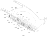
FIG. 1 is a schematic diagram illustrating a state of a vehicle frame assembly according to an embodiment. -
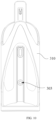
FIG. 2 is a schematic diagram illustrating another state of the vehicle frame assembly ofFIG. 1 . -
FIG. 3 is an exploded view of the vehicle frame assembly illustrated inFIG. 1 . -
FIG. 4 is a cross-sectional view illustrating a battery mounting frame of the vehicle frame assembly illustrated inFIG. 1 . -
FIG. 5 is a partial enlarged view of the battery mounting frame illustrated inFIG. 4 . -
FIG. 6 is a schematic diagram illustrating an easy loading and unloading structure of the battery mounting frame of the vehicle frame assembly illustrated inFIG. 1 from another perspective. -
FIG. 7 is a cross-sectional view illustrating the easy loading and unloading structure taken from A-A inFIG. 6 . -
FIG. 8 is an exploded view of a partial structure of the easy loading and unloading structure illustrated inFIG. 7 . -
FIG. 9 is a schematic diagram illustrating a battery holder of the battery mounting frame illustrated inFIG. 4 from a perspective. -
FIG. 10 is a schematic diagram illustrating the battery holder illustrated inFIG. 9 from another perspective. - For ease of understanding of the present disclosure, the present disclosure will be comprehensively described with reference to the accompanying drawings. Preferred embodiments of the present disclosure are presented in the accompanying drawings. However, the present disclosure may be implemented in many different forms and is not limited to the embodiments described herein. Rather, the purpose of providing these embodiments is to enable thorough and comprehensive understanding of the contents of the present disclosure.
- It is notable that, when an element is described as being "fixed to" another element, it may be directly on the another element or there may be an intermediate element. When an element is considered to be "connected" to another element, it may be directly connected to another element or there may be an intermediate element. Terms "vertical," "horizontal," "left," "right," and the like as used herein are for illustrative purposes only and are not meant to be the only implementation.
- Unless otherwise defined, all technical and scientific terms used herein have the same meaning as commonly understood by those skilled in the art of the present disclosure. The terminologies used herein in the specification of the present disclosure are for the purpose of describing specific embodiments only, and are not intended to limit the present disclosure. The term "and/or" as used herein includes any and all combinations of one or more related listed items.
- The present disclosure provides an easy loading and unloading structure. The easy loading and unloading structure includes a fixing bracket, a rotatable bracket, an elastic positioning post, and an auxiliary limiting member. The fixing bracket is provided with a first positioning hole and a second positioning hole. The rotatable bracket is rotatably connected to the fixing bracket, and a rotation sliding groove is provided in the rotatable bracket. The elastic positioning post is connected to a side of the rotatable bracket facing the fixing bracket, and is arranged to elastically engage with and engage against the first positioning hole or the second positioning hole. The auxiliary limiting member is connected to the fixing bracket and extends into the rotation sliding groove. During a process that the rotatable bracket is rotated relative to the fixing bracket, a side of the rotatable bracket away from the fixing bracket is configured to be restrained by the auxiliary limiting member.
- In the easy loading and unloading structure, the battery holder may be mounted on the rotatable bracket, and the fixing bracket may be fixed onto the vehicle frame. Since the rotatable bracket is rotatably connected to the fixing bracket, the rotatable bracket can be rotated to a predetermined angle relative to the fixing bracket; as such, when there is a need to unload and load the battery, the user can quickly unload the battery from the battery holder or load the battery into the battery holder. Thus, the battery is enabled to be quickly unloaded and loaded, especially for a vehicle frame having a relatively narrow space. In the easy loading and unloading structure mentioned above, during the process that the rotatable bracket is rotated relative to the fixing bracket, the elastic positioning post is arranged to elastically engage with and engage against the first positioning hole or the second positioning hole, so that the rotatable bracket can be correspondingly positioned at two different positions relative to the fixing bracket, thereby satisfying a positioning requirement for unloading and loading as well as holding the battery. For example, when the elastic positioning post is elastically engaged with and abuts against the first positioning hole, the rotatable bracket is rotated to a first predetermined position relative to the fixing bracket, in this case, the battery can be unloaded and loaded. When the elastic positioning post is elastically engaged with and abuts against the second positioning hole, the rotatable bracket is rotated to a second predetermined position relative to the fixing bracket, in this case, the battery is reliably received on the vehicle frame with the easy loading and unloading structure. When the rotatable bracket is rotated relative to the fixing bracket, the elastic positioning post is arranged to elastically engage with and engage against the first positioning hole or the second positioning hole, so that the elastic positioning post can play a limiting and supporting role at positions where the rotatable bracket is rotated to relative to the fixing bracket. In addition, the auxiliary limiting member is connected to the fixing bracket and extends into the rotation sliding groove; and when the rotatable bracket is rotated relative to the fixing bracket, a side of the rotatable bracket away from the fixing bracket is configured to be restrained by the auxiliary limiting member; as such, it avoids the rotatable bracket from shaking towards a side away from the fixing bracket during the process that the rotatable bracket is rotated relative to the fixing bracket. This avoids the shaking caused during the rotation of the rotatable base relative to the fixing base in the existing battery mounting frame, improves the reliability of the rotation of the rotatable base relative to the fixing base, and improves the service reliability of the easy loading and unloading structure.
- In order to better understand technical solutions and beneficial effects of the disclosure, the present disclosure will be further described in detail below with reference to specific implementations.
- As illustrated in
FIG. 1 andFIG. 2 , avehicle frame assembly 10 is provided in an embodiment of the present disclosure, which may be used in an electric vehicle or other electric devices. The electric vehicle may be an electric two-wheeled vehicle or an electric tricycle or an electric four-wheeled vehicle. In the embodiments, the electric two-wheeled vehicle may be an electric bicycle or an electric motorcycle. - As illustrated in
FIG. 1 andFIG. 2 , in some embodiments, thevehicle frame assembly 10 includes abattery 100, avehicle frame 200 and abattery mounting frame 300. Thevehicle frame 200 is provided with a mountingportion 201, and thebattery mounting frame 300 is fixedly mounted to the mountingportion 201. Thevehicle frame 200 may be atriangular frame 200 or a V-shapedframe 200 orother frames 200. - As illustrated in
FIG. 3 to FIG. 7 , in some embodiments, thebattery mounting frame 300 includes abattery holder 310 and an easy loading andunloading structure 320, and thebattery holder 310 is mounted on the easy loading andunloading structure 320. The easy loading andunloading structure 320 includes a fixingbracket 321, arotatable bracket 323, anelastic positioning post 325, and an auxiliary limitingmember 327. The fixingbracket 321 is configured to be connected to thevehicle frame 200. Specifically, the fixingbracket 321 is connected to the mountingportion 201. The fixingbracket 321 is provided thereon with afirst positioning hole 3211 and asecond positioning hole 3213, and each of the first positioning hole and the second positioning hole may be a blind hole or a recess. Therotatable bracket 323 is rotatably connected to the fixingbracket 321, and arotation sliding groove 3232 is provided in therotatable bracket 323. In the embodiments, thebattery holder 310 is mounted on therotatable bracket 323, and thebattery holder 310 is detachably sleeved on the battery 100 (that is, thebattery 100 is detachably received in the battery bolder 310). This connects thebattery 100 to therotatable bracket 323 through thebattery holder 310, enables thebattery 100 to be unloaded from and loaded onto thebattery holder 310, and improves the use convenience of thebattery mounting frame 300. Further, thebattery holder 310 is in a structure formed by over-molding, so that thebattery 100 can be quickly removed from or placed into thebattery holder 310. - As illustrated in
FIG. 1 ,FIG. 2 ,FIG. 7 andFIG. 8 , in some embodiments, theelastic positioning post 325 is connected to a side of therotatable bracket 323 facing the fixingbracket 321, and theelastic positioning post 325 is capable of being elastically engaged with and abutting against thefirst positioning hole 3211 or thesecond positioning hole 3213. As illustrated inFIG. 2 andFIG. 8 , when theelastic positioning post 325 is elastically engaged with and abuts against thefirst positioning hole 3211, therotatable bracket 323 is rotated to a first predetermined position relative to the fixingbracket 321; in this case, it is rotated to be in an open state, that is, therotatable bracket 323 is at a predetermined angle relative to the fixingbracket 321, and thebattery 100 can be then unloaded and loaded, especially for avehicle frame 200 having a narrow space. As such, a space required for unloading and loading the battery can be offered by rotating the rotatable bracket out. As illustrated inFIG. 1 andFIG. 8 , when theelastic positioning post 325 is elastically engaged with and abuts against thesecond positioning hole 3213, therotatable bracket 323 is rotated to a second predetermined position relative to the fixingbracket 321; in this case, it is in a closed state in which therotatable bracket 323 is substantially parallel to the fixingbracket 321, and thebattery 100 is reliably received in thevehicle frame 200 with the easy loading andunloading structure 320. - As illustrated in
FIG. 4 , in some embodiments, theauxiliary limiting member 327 is connected to the fixingbracket 321 and extends into therotation sliding groove 3232, and relative sliding happens between the auxiliary limitingmember 327 and therotation sliding groove 3232 when therotatable bracket 323 is rotated. When therotatable bracket 323 is rotated relative to the fixingbracket 321, a side of therotatable bracket 323 away from the fixingbracket 321 is configured to be restrained by theauxiliary limiting member 327, so that therotatable bracket 323 is prevented, during the process that therotatable bracket 323 is rotated relative to the fixingbracket 321, from shaking in a direction perpendicular to a plane where therotatable bracket 323 is rotated. In addition, the relative sliding between the auxiliary limitingmember 327 and therotation sliding groove 3232 that exists when therotatable bracket 323 is rotated relative to the fixingbracket 321, improves the smoothness and reliability of the rotation of therotatable bracket 323 relative to the fixingbracket 321. - With the easy loading and
unloading structure 320, thebattery mounting frame 300 and thevehicle frame assembly 10 mentioned above, thebattery holder 310 may be mounted on therotatable bracket 323, and the fixingbracket 321 may be fixed on thevehicle frame 200. Since therotatable bracket 323 is rotatably connected to the fixingbracket 321, therotatable bracket 323 can be rotated to a predetermined angle relative to the fixingbracket 321; as such, when there is a need to unload and load thebattery 100, the user can quickly unload thebattery 100 from thebattery holder 310 or load thebattery 100 onto thebattery holder 310. Thus, thebattery 100 is enabled to be quickly unloaded and loaded, especially for avehicle frame 200 having a relatively narrow space. In the easy loading andunloading structure 320, during the process that therotatable bracket 323 is rotated relative to the fixingbracket 321, theelastic positioning post 325 is arranged to elastically engage with and abut against thefirst positioning hole 3211 or thesecond positioning hole 3213, so that therotatable bracket 323 can be correspondingly positioned at two different positions relative to the fixingbracket 321, thereby satisfying a positioning requirement for unloading and loading as well as holding thebattery 100. Through the rotation of therotatable bracket 323 relative to the fixingbracket 321, theelastic positioning post 325 is arranged to elastically engage with and abut against thefirst positioning hole 3211 or thesecond positioning hole 3213, so that theelastic positioning post 325 can play a limiting and supporting role at positions where therotatable bracket 323 is rotated to relative to the fixingbracket 321. In addition, theauxiliary limiting member 327 is connected to the fixingbracket 321 and extends into therotation sliding groove 3232, and when therotatable bracket 323 is rotated relative to the fixingbracket 321, a side of therotatable bracket 323 away from the fixingbracket 321 is configured to be restrained by theauxiliary limiting member 327; as such, it avoids therotatable bracket 323 from shaking towards a side away from the fixingbracket 321 during the process that therotatable bracket 323 is rotated relative to the fixingbracket 321. This avoids the shaking caused during the rotation of the rotatable base relative to the fixing base in the existingbattery mounting frame 300, that is, this avoids therotatable bracket 323 from shaking up and down relative to the fixingbracket 321 during the process that therotatable bracket 323 is rotated relative to the fixingbracket 321. Thus, the reliability of the rotation of the rotatable base relative to the fixing base is improved, and the service reliability of the easy loading andunloading structure 320 is improved. - As illustrated in
FIG. 3 to FIG. 5 , further, the fixingbracket 321 is provided with a first mountinghole 302, and the mountingportion 201 is provided with a first threadedhole 2012. The easy loading andunloading structure 320 further includes afirst screw rod 322, and thefirst screw rod 322 passes through both the first mountinghole 302 and the first threadedhole 2012. In addition, thefirst screw rod 322 is in thread connection with thevehicle frame 200, so that the fixingbracket 321 is reliably mounted on thevehicle frame 200. - As illustrate in
FIG. 3 to FIG. 6 , in some embodiments, there are two auxiliary limitingmembers 327 and tworotation sliding grooves 3232, and each of the two auxiliary limitingmembers 327 is arranged in a corresponding one of the tworotation sliding grooves 3232. A second connectinghole 308 is provided between the tworotation sliding grooves 3232. This better facilitates the relative sliding between the auxiliary limitingmember 327 and therotation sliding groove 3232 when therotatable bracket 323 is rotated relative to the fixingbracket 321, better avoids therotatable bracket 323 from shaking up and down relative to the fixingbracket 321 during the process that therotatable bracket 323 is rotated relative to the fixingbracket 321, and further improves the stability and reliability of the rotation of therotatable bracket 323 relative to the fixingbracket 321. Similarly, as illustrated inFIG. 8 , there are twofirst positioning holes 3211 and twosecond positioning holes 3213; and at each of two opposite ends of the fixingbracket 321, a pair of thefirst positioning holes 3211 and thesecond positioning holes 3213 is defined. - As illustrated in
FIG. 3 to FIG. 6 , in some embodiments, the easy loading andunloading structure 320 further includes a lockingmember 326. The fixingbracket 321 is provided with a first connectinghole 306, therotatable bracket 323 is provided with the second connectinghole 308, and the second connectinghole 308 is aligned and communicated with the first connectinghole 306. The lockingmember 326 passes through both the first connectinghole 306 and the second connectinghole 308, which enables therotatable bracket 323 to be rotatably connected to the fixingbracket 321. In the embodiments, the lockingmember 326 is a screw assembly or a bolt assembly. - As illustrated in
FIG. 3 to FIG. 6 , further, the lockingmember 326 includes alocking screw 3262, alocking washer 3264 and anut 3266. The lockingscrew 3262 passes through both the first connectinghole 306 and the second connectinghole 308, and a head of thelocking screw 3262 abuts, through the lockingwasher 3264, against a side of therotatable bracket 323 away from the fixingbracket 321. Thenut 3266 is sleeved on a rod portion of thelocking screw 3262, and is screwed with the lockingscrew 3262. Thenut 3266 is confined at a side of the fixingbracket 321 away from therotatable bracket 323. This avoids the lockingscrew 3262 from being driven to rotate during the process that therotatable bracket 323 is rotated relative to the fixingbracket 321, that is, this avoids thenut 3266 from being easily dropped from the lockingscrew 3262 during the process that therotatable bracket 323 is rotated relative to the fixingbracket 321, thereby ensuring that therotatable bracket 323 is rotatably connected with the fixingbracket 321 reliably. As illustrated inFIG. 4 andFIG. 5 , further, therotatable bracket 323 is provided with afirst positioning groove 3231 communicated with the second connectinghole 308. The lockingwasher 3264 is located in and abuts against thefirst positioning groove 3231, so that the lockingwasher 3264 is better confined at therotatable bracket 323. Furthermore, the fixingbracket 321 is provided with asecond positioning groove 3212 communicated with the first connectinghole 306. Thenut 3266 is located in thesecond positioning groove 3212 and is connected with the fixingbracket 321, which enables thenut 3266 to be better confined at the fixingbracket 321. - As illustrated in
FIG. 3 to FIG. 6 , in some embodiments, apreloading deformation gap 321a is provided between the fixingbracket 321 and therotatable bracket 323. When therotatable bracket 323 is rotationally fixed on the fixingbracket 321 by means of the lockingmember 326, therotatable bracket 323 may deform towards the preloadingdeformation gap 321a, thereby further avoiding the shaking of therotatable bracket 323 relative to the fixingbracket 321, especially in the process that therotatable bracket 323 is rotated relative to the fixingbracket 321. In the embodiments, thepreloading deformation gap 321a is staggered from a position where the lockingmember 326 is fixed to therotatable bracket 323, and thepreloading deformation gap 321a is provided on two sides of the lockingmember 326. Specifically, there are two auxiliary limitingmembers 327, and the two auxiliary limitingmembers 327 are provided on two sides of the lockingmember 326. Thepreloading deformation gap 321a is provided between the fixingbracket 321 and therotatable bracket 323, and thepreloading deformation gap 321a is also located in a region between the lockingmember 326 and each auxiliary limitingmember 327. As such, after therotatable bracket 323 is assembled onto the fixingbracket 321, therotatable bracket 323 is enabled to better deform towards the preloadingdeformation gap 321a, thereby better preventing therotatable bracket 323 from shaking up and down relative to the fixingbracket 321. - As illustrated in
FIG. 4 andFIG. 5 , in some embodiments, a side of the fixingbracket 321 close to therotatable bracket 323 is provided with a first supportingprotrusion 321b and a second supportingprotrusion 321c. The first supportingprotrusion 321b is arranged around the first connectinghole 306, and the second supportingprotrusion 321c is arranged around both thefirst positioning hole 3211 and thesecond positioning hole 3213. Thepreloading deformation gap 321a is defined among the fixingbracket 321, therotatable bracket 323, the first supportingprotrusion 321b and the second supportingprotrusion 321c, which reduces the difficulty of manufacturing thepreloading deformation gap 321a, and simplifies the structure of the easy loading andunloading structure 320. In the embodiments, when therotatable bracket 323 is rotatably connected to the fixingbracket 321, therotatable bracket 323 deforms towards the preloadingdeformation gap 321a. - As illustrated in
FIG. 2 ,FIG. 3 andFIG. 8 , further, the fixingbracket 321 includes abracket body 323a and a wear-resistant member 323b. Each of the first supportingprotrusion 321b and the second supportingprotrusion 321c protrudes from thebracket body 323a. The second supportingprotrusion 321c surrounds the wear-resistant member 323b, that is, the wear-resistant member 323b is embedded in the second supporting protrusion, so that the wear-resistant member 323b is better fixedly connected to the second supportingprotrusion 321c, and the fixingbracket 321 is more compact in structure. Each of asecond mounting hole 303 and the second connectinghole 308 is provided inratable bracket 323, the first connectinghole 306 is provided in thebracket body 323a, and each of thefirst positioning hole 3211 and thesecond positioning hole 3213 is provided in thebracket body 323a. The wear-resistant member 323b is provided with a first throughhole 3238 and a second throughhole 3239, the first through hole is correspondingly communicated with thefirst positioning hole 3211, and the second through hole is correspondingly communicated with thesecond positioning hole 3213. It enables the fixingbracket 321 to be light in weight and low in manufacturing cost, and enables each of thefirst positioning hole 3211 and thesecond positioning hole 3213 to have better wear resistance. In the embodiments, thewear member 323b is a metal piece. Furthermore, the wear-resistant member 323b is provided with aconvex rib 3235 protruding therefrom, and the convex rib is embraced by the second supportingprotrusion 321c. - As illustrated in
FIG. 2 ,FIG. 3 andFIG. 6 , further, therotation sliding groove 3232 is a waist-shaped groove, which better facilitates the relative sliding between the auxiliary limitingmember 327 and therotation sliding groove 3232 when therotatable bracket 323 is rotated relative to the fixingbracket 321. - As illustrated in
FIG. 2 ,FIG. 3 andFIG. 7 , further, when therotatable bracket 323 is rotated to a predetermined angle relative to the fixingbracket 321, theelastic positioning post 325 is elastically engaged with and abuts against thefirst positioning hole 3211, and then the easy loading andunloading structure 320 is the open state through rotation. In this case, thebattery 100 may be unloaded and loaded without being affected by the space of the vehicle frame, especially for avehicle frame 200 having a narrow space. In the embodiments, the predetermined angle is 10° to 65°. In the embodiments, the predetermined angle is 30°. - As illustrated in
FIG. 2 ,FIG. 3 andFIG. 6 , in some embodiments, theauxiliary limiting member 327 includes arotation guiding post 3272 and a mountingmember 3274. Therotation guiding post 3272 protrudes from the side of the fixingbracket 321 close to therotatable bracket 323, and therotation guiding post 3272 extends into therotation sliding groove 3232, and therotation sliding groove 3232 is movable relative to therotation guiding post 3272. The mountingmember 3274 is connected to therotation guiding post 3272, and when therotatable bracket 323 is rotated relative to the fixingbracket 321, the side of therotatable bracket 323 away from the fixingbracket 321 is configured to be restrained by the mountingmember 3274. As such, theauxiliary limiting member 327 is enabled to reliably guide the rotation of therotatable bracket 323 relative to the fixingbracket 321, and the auxiliary limitingmember 327 can prevent therotatable bracket 323 from shaking during the process that therotatable bracket 323 is rotated relative to the fixingbracket 321. - As illustrated in
FIG.2 ,FIG. 3 andFIG. 6 , in some embodiments, the mountingmember 3274 is detachably connected to therotation guiding post 3272. In the embodiments, therotation guiding post 3272 is provided with a fixing hole, and the mountingmember 3274 is located in the fixing hole and is in thread connection with therotation guiding post 3272, which enables the mountingmember 3274 to be detachably connected to therotation guiding post 3272. It may be understood that, in other embodiments, the mountingmember 3274 is not limited to being in thread connected with therotation guiding post 3272. For example, the mountingmember 3274 is snap fitted with therotation guiding post 3272. Certainly, in other embodiments, the mountingmember 3274 is not only limited to being detachably connected to therotation guiding post 3272. For example, the mountingmember 3274 is riveted or welded to therotation guiding post 3272. - As illustrated in
FIG. 2 ,FIG. 3 andFIG. 6 , further, the mountingmember 3274 is a screw or a self-tapping screw. In the embodiments, the mountingmember 3274 is a self-tapping screw, which enables the mountingmember 3274 to better limit therotatable bracket 323. - As illustrated in
FIG. 2 ,FIG. 4 andFIG. 6 , further, therotatable bracket 323 is further provided with ananti-shaking limiting groove 3234 communicated with therotation sliding groove 3232. An end of the mountingmember 3274 facing away from the fixingbracket 321 is located in theanti-shaking limiting groove 3234, and there is a gap between the end of the mountingmember 3274 facing away from the fixingbracket 321 and a bottom of theanti-shaking limiting groove 3234, which enables smooth sliding along the limiting groove and the rotation sliding groove when therotatable bracket 323 is rotated relative to the fixingbracket 321. - As illustrated in
FIG. 3 ,FIG. 4 andFIG. 8 , in some embodiments, the diameter of the end of the mountingmember 3274 facing away from the fixingbracket 321 is greater than the width of therotation sliding groove 3232; as such, when therotatable bracket 323 is rotated relative to the fixingbracket 321, the end of the mountingmember 3274 facing away from the fixingbracket 321 can reliably prevent therotatable bracket 323 from shaking. - As illustrated in
FIG. 4 ,FIG. 6 andFIG. 9 , in some embodiments, an outer wall of thebattery holder 310 close to therotatable bracket 323 is provided thereon with a limitingflange 313. Therotatable bracket 323 is provided with a limitinggroove 3236, that is, therotatable bracket 323 is provided with a grooved skeleton structure. The limitingflange 313 is located in the limitinggroove 3236, that is, the limitingflange 313 is received in the limitinggroove 3236. Since the limitingflange 313 is located in the limitinggroove 3236, thebattery holder 310 can be better in deformation fit after being fastened to therotatable bracket 323 by means of a fixingmember 330, and thebattery holder 310 can be prevented from shaking relative to therotatable bracket 323. Thebattery holder 310 can be better fixed on therotatable bracket 323. - As illustrated in
FIG. 4 ,FIG. 5 ,FIG. 9 andFIG. 10 , further, thebattery holder 310 is provided with asecond mounting hole 303, and therotatable bracket 323 is provided with asecond screw hole 304. The easy loading andunloading structure 320 further includes asecond screw rod 324. Thesecond screw rod 324 passes through each of thesecond mounting hole 303 and thesecond screw hole 304, and thesecond screw rod 324 is screwed with therotatable bracket 323. This enables thebattery holder 310 to reliably be mounted on therotatable bracket 323. In the embodiments, thesecond screw rod 324 is a screw fastener or a nut bolt, and the fixing hole is a threaded hole. Specifically, thesecond screw rod 324 is a machine hexagon screw. - As illustrated in
FIG. 4 andFIG. 6 , in some embodiments, a limitingboss 3237 is provided in the limitinggroove 3236, the limitingflange 313 is provided with afixing limiting groove 3131, and the limitingboss 3237 is located in thefixing limiting groove 3131 and connected with thebattery holder 310. As such, thebattery holder 310 is better prevented from shaking relative to therotatable bracket 323, and thebattery holder 310 can be better fixedly connected with therotatable bracket 323. In the embodiments, the limitingboss 3237 is skeleton-shaped, which enables the limitingboss 3237 to have a good supporting strength, avoids large deformation caused when thebattery holder 310 is received in the limitinggroove 3236, thereby enabling thebattery holder 310 to be better fixedly connected with therotatable bracket 323. - As illustrated in
FIG. 1 to FIG. 6 , the present disclosure further provides an electric vehicle (not illustrated), which includes thevehicle frame assembly 10 described in any one of the above embodiments. Further, thevehicle frame assembly 10 includes thebattery 100, thevehicle frame 200 and thebattery mounting frame 300. Thevehicle frame 200 is provided with the mountingportion 201, and thebattery mounting frame 300 is fixedly mounted to the mountingportion 201. Thebattery mounting frame 300 includes thebattery holder 310 and the easy loading andunloading structure 320, and thebattery holder 310 is mounted on the easy loading andunloading structure 320. The easy loading andunloading structure 320 includes the fixingbracket 321, therotatable bracket 323, theelastic positioning post 325, and the auxiliary limitingmember 327. The fixingbracket 321 is configured to be connected to thevehicle frame 200. Specifically, the fixingbracket 321 is connected to the mountingportion 201. The fixingbracket 321 is provided with thefirst positioning hole 3211 and thesecond positioning hole 3213. Therotatable bracket 323 is rotatably connected to the fixingbracket 321, and therotatable bracket 323 is provided with therotation sliding groove 3232. In the embodiments, thebattery holder 310 is mounted on therotatable bracket 323, and thebattery holder 310 is detachably sleeved on thebattery 100, so that thebattery 100 is connected to therotatable bracket 323 through thebattery holder 310. Since thebattery 100 can be unloaded from and loaded onto thebattery holder 310, the use convenience of thebattery mounting frame 300 is improved. - In some embodiments, the
elastic positioning post 325 is connected to the side of therotatable bracket 323 facing the fixingbracket 321, and theelastic positioning post 325 is arranged to elastically engage with and abut against thefirst positioning hole 3211 or thesecond positioning hole 3213. When theelastic positioning post 325 is elastically engaged with and abuts against thefirst positioning hole 3211, therotatable bracket 323 is rotated to a first predetermined position relative to the fixingbracket 321; in this case, it is rotated to be in the open state, that is, therotatable bracket 323 is at a predetermined angle relative to the fixingbracket 321, and thebattery 100 may be unloaded and loaded, especially for avehicle frame 200 having a narrow space. When theelastic positioning post 325 is elastically engaged with and abuts against thesecond positioning hole 3213, therotatable bracket 323 is rotated to a second predetermined position relative to the fixingbracket 321; in this case, it is in the closed state in which therotatable bracket 323 is substantially parallel to the fixingbracket 321, and thebattery 100 is reliably received on thevehicle frame 200 with the easy loading andunloading structure 320. - In some embodiments, the
auxiliary limiting member 327 is connected to the fixingbracket 321. The auxiliary limitingmember 327 extends into therotation sliding groove 3232, and relative sliding happens between the auxiliary limitingmember 327 and therotation sliding groove 3232 when therotatable bracket 323 is rotated. When therotatable bracket 323 is rotated relative to the fixingbracket 321, the side of therotatable bracket 323 away from the fixingbracket 321 is configured to be restrained by theauxiliary limiting member 327, so that therotatable bracket 323 is prevented, during the process that therotatable bracket 323 is rotated relative to the fixingbracket 321, from shaking in a direction perpendicular to a plane where therotatable bracket 323 is rotated. In addition, the relative sliding between the auxiliary limitingmember 327 and therotation sliding groove 3232 that exists when therotatable bracket 323 is rotated relative to the fixingbracket 321, improves the smoothness and reliability of the rotation of therotatable bracket 323 relative to the fixingbracket 321. - In the electric vehicle mentioned above, the
battery holder 310 may be mounted on therotatable bracket 323, and the fixingbracket 321 may be fixed on thevehicle frame 200. Since therotatable bracket 323 is rotatably connected to the fixingbracket 321, therotatable bracket 323 can be rotated to a predetermined angle relative to the fixingbracket 321; as such, when there is a need to unload and load thebattery 100, the user can quickly unload thebattery 100 from thebattery holder 310 or load thebattery 100 onto thebattery holder 310. Thus, thebattery 100 is enabled to be quickly unloaded and loaded, especially for avehicle frame 200 having a relatively narrow space. In the easy loading andunloading structure 320, during the process that therotatable bracket 323 is rotated relative to the fixingbracket 321, theelastic positioning post 325 is arranged to elastically engage with and abut against thefirst positioning hole 3211 or thesecond positioning hole 3213, so that therotatable bracket 323 can be correspondingly positioned at two different positions relative to the fixingbracket 321, thereby satisfying a positioning requirement for unloading and loading as well as holding thebattery 100. Through the rotation of therotatable bracket 323 relative to the fixingbracket 321, theelastic positioning post 325 is arranged to elastically engage with and abut against thefirst positioning hole 3211 or thesecond positioning hole 3213, so that theelastic positioning post 325 can play a limiting and supporting role at positions where therotatable bracket 323 is rotated to relative to the fixingbracket 321. In addition, theauxiliary limiting member 327 is connected to the fixingbracket 321 and extends into therotation sliding groove 3232, and when therotatable bracket 323 is rotated relative to the fixingbracket 321, the side of therotatable bracket 323 away from the fixingbracket 321 is configured to be restrained by theauxiliary limiting member 327; as such, it avoids therotatable bracket 323 from shaking towards a side away from the fixingbracket 321 during the process that therotatable bracket 323 is rotated relative to the fixingbracket 321. This avoids the shaking caused during the rotation of the rotatable base relative to the fixing base in the existingbattery mounting frame 300, that is, this avoids therotatable bracket 323 from shaking up and down relative to the fixingbracket 321 during the process that therotatable bracket 323 is rotated relative to the fixingbracket 321. Thus, the reliability of the rotation of the rotatable base relative to the fixing base is improved, and the service reliability of the easy loading andunloading structure 320 is improved. - Different from the related art, the present disclosure brings about at least advantages as follows.
- 1. In the easy loading and
unloading structure 320 mentioned above, thebattery holder 310 may be mounted on therotatable bracket 323, and the fixingbracket 321 may be fixed onto thevehicle frame 200. Since therotatable bracket 323 is rotatably connected to the fixingbracket 321, therotatable bracket 323 can be rotated to a predetermined angle relative to the fixingbracket 321; as such, when there is a need to unload and load thebattery 100, the user can quickly unload thebattery 100 from thebattery holder 310 or load thebattery 100 into thebattery holder 310. Thus, thebattery 100 is enabled to be quickly unloaded and loaded, especially for avehicle frame 200 having a relatively narrow space. - 2. In the easy loading and
unloading structure 320 mentioned above, during the process that therotatable bracket 323 is rotated relative to the fixingbracket 321, theelastic positioning post 325 is arranged to elastically engage with and engage against thefirst positioning hole 3211 or thesecond positioning hole 3213, so that therotatable bracket 323 can be correspondingly positioned at two different positions relative to the fixingbracket 321, thereby satisfying a positioning requirement for unloading and loading as well as holding thebattery 100. For example, when theelastic positioning post 325 is elastically engaged with and abuts against thefirst positioning hole 3211, therotatable bracket 323 is rotated to a first predetermined position relative to the fixingbracket 321, in this case, thebattery 100 can be unloaded and loaded. When theelastic positioning post 325 is elastically engaged with and abuts against thesecond positioning hole 3213, therotatable bracket 323 is rotated to a second predetermined position relative to the fixingbracket 321, in this case, thebattery 100 is reliably received on thevehicle frame 200 with the easy loading andunloading structure 320. - 3. When the
rotatable bracket 323 is rotated relative to the fixingbracket 321, theelastic positioning post 325 is arranged to elastically engage with and engaging against thefirst positioning hole 3211 or thesecond positioning hole 3213, so that theelastic positioning post 325 can play a limiting and supporting role at positions where therotatable bracket 323 is rotated to relative to the fixingbracket 321. In addition, theauxiliary limiting member 327 is connected to the fixingbracket 321 and extends into therotation sliding groove 3232; and when therotatable bracket 323 is rotated relative to the fixingbracket 321, wherein the side of therotatable bracket 323 away from the fixingbracket 321 is configured to be restrained by theauxiliary limiting member 327; as such, it avoids therotatable bracket 323 from shaking towards a side away from the fixingbracket 321 during the process that therotatable bracket 323 is rotated relative to the fixingbracket 321. This avoids the shaking caused during the rotation of the rotatable base relative to the fixing base in the existingbattery mounting frame 300, improves the reliability of the rotation of the rotatable base relative to the fixing base, and improves the service reliability of the easy loading andunloading structure 320. - The foregoing embodiments only illustrate several implementations of the present disclosure, and their descriptions are relatively specific and detailed, but they cannot be construed as limiting the scope of the present disclosure. It is notable for those skilled in the art that, several variations and modifications may be made by those skilled in the art without departing from the concept of the present disclosure, and all of them should fall within the protection scope of the present disclosure. Accordingly, the protection scope of the present disclosure is subject to the appended claims.
Claims (12)
- A loading and unloading structure (320), comprising:a fixing bracket (321), provided with a first positioning hole (3211) and a second positioning hole (3213);a rotatable bracket (323) rotatably connected to the fixing bracket (321), wherein a rotation sliding groove (3232) is provided in the rotatable bracket (323);an elastic positioning post (325) connected to a side of the rotatable bracket (323) facing the fixing bracket (321), wherein the elastic positioning post (325) is arranged to elastically engage with and abut against the first positioning hole (3211) or the second positioning hole (3213); andan auxiliary limiting member (327) connected to the fixing bracket (321), wherein the auxiliary limiting member (327) extends into the rotation sliding groove (3232), and a side of the rotatable bracket (323) away from the fixing bracket (321) is configured to be restrained by the auxiliary limiting member (327) when the rotatable bracket (323) is rotated relative to the fixing bracket (321).
- The loading and unloading structure (320) of claim 1, wherein there are two auxiliary limiting members (327) and two rotation sliding grooves (3232), and each of the two auxiliary limiting members (327) is arranged in a corresponding one of the two rotation sliding grooves (3232).
- The loading and unloading structure (320) any one of claims 1 and 2, wherein the loading and unloading structure (320) further comprises a locking member (326), the fixing bracket (321) is provided with a first connecting hole (306), the rotatable bracket (323) is provided with a second connecting hole (308) located between the two rotation sliding grooves (3232), the second connecting hole (308) is aligned and communicated with the first connecting hole (306), and the locking member (326) passes through both the first connecting hole (306) and the second connecting hole (308) in such a manner that the rotatable bracket (323) is rotatably connected with the fixing bracket (321).
- The loading and unloading structure (320) any one of claims 1 to 3, wherein the auxiliary limiting member (327) comprises a rotation guiding post (3272) and a mounting member (3274), the rotation guiding post (3272) protrudes from a side of the fixing bracket (321) close to the rotatable bracket (323) and extends into the rotation sliding groove (3232), and there is relative sliding between the rotation guiding post (3272) and the rotation sliding groove (3232) when the rotatable bracket (323) is rotated; the mounting member (3274) is connected to the rotation guiding post (3272), and wherein the side of the rotatable bracket (323) away from the fixing bracket (321) is configured to be restrained by the mounting member (3274) when the rotatable bracket (323) is rotated relative to the fixing bracket (321).
- The loading and unloading structure (320) of claim 4, wherein the mounting member (3274) is detachably connected to the rotation guiding post (3272).
- The loading and unloading structure (320) of claim 4, wherein the rotation guiding post (3272) is provided with a fixing hole, and the mounting member (3274) is located in the fixing hole and in thread connection with the rotation guiding post (3272).
- The loading and unloading structure (320) of any one of claims 4 to 6, wherein a diameter of an end of the mounting member (3274) away from the fixing bracket (321) is greater than a width of the rotation sliding groove (3232).
- The loading and unloading structure (320) of claim 3, wherein there is a preloading deformation gap (321a) between the fixing bracket (321) and the rotatable bracket (323).
- The loading and unloading structure (320) of claim 8, wherein a side of the fixing bracket (321) close to the rotatable bracket (323) is provided with a first supporting protrusion (321b) and a second supporting protrusion (321c), the first supporting protrusion (321b) is arranged around the first connecting hole (306), and the second supporting protrusion (321c) is arranged around both the first positioning hole (3211) and the second positioning hole (3213); the preloading deformation gap (321a) is defined between the fixing bracket (321), the rotatable bracket (323), the first supporting protrusion (321b) and the second supporting protrusion (321c); and when the rotatable bracket (323) is rotatably connected to the fixing bracket (321), the rotatable bracket (323) is arranged to deform toward the preloading deformation gap (321a).
- A battery mounting frame (300), comprising a battery holder (310) and the loading and unloading structure (320) of any one of claims 1 to 9, wherein the battery holder (310) is mounted on the rotatable bracket (323), the battery holder (310) is configured to be detachably sleeved on a battery (100), and the fixing bracket (321) is configured to be connected onto a vehicle frame (200).
- A vehicle frame assembly (10), comprising a battery (100), a vehicle frame (200) and the battery (100) mounting frame of claim 10, wherein the vehicle frame (200) is provided with a mounting portion (201), the fixing bracket (321) is connected onto the mounting portion (201), and the battery holder (310) is detachably sleeved on the battery (100).
- An electric vehicle, comprising the vehicle frame assembly (10) of claim 11.
Applications Claiming Priority (1)
| Application Number | Priority Date | Filing Date | Title |
|---|---|---|---|
| CN202310654463.9A CN116534167B (en) | 2023-06-02 | 2023-06-02 | Convenient assembly and disassembly structure, power battery mounting rack, frame assembly and electric vehicle |
Publications (3)
| Publication Number | Publication Date |
|---|---|
| EP4474259A1 true EP4474259A1 (en) | 2024-12-11 |
| EP4474259B1 EP4474259B1 (en) | 2026-02-25 |
| EP4474259C0 EP4474259C0 (en) | 2026-02-25 |
Family
ID=87450746
Family Applications (1)
| Application Number | Title | Priority Date | Filing Date |
|---|---|---|---|
| EP24178749.8A Active EP4474259B1 (en) | 2023-06-02 | 2024-05-29 | Easy loading and unloading structure, battery mounting frame, vehicle frame assembly, and electric vehicle |
Country Status (2)
| Country | Link |
|---|---|
| EP (1) | EP4474259B1 (en) |
| CN (1) | CN116534167B (en) |
Citations (6)
| Publication number | Priority date | Publication date | Assignee | Title |
|---|---|---|---|---|
| US5251777A (en) * | 1992-11-16 | 1993-10-12 | Great Relief Products, Inc. | Water bottle and mounting bracket |
| CN2571651Y (en) * | 2002-09-27 | 2003-09-10 | 财荣压铸股份有限公司 | Rotatable water bottle cage connection seat structure |
| CN213735350U (en) * | 2020-10-30 | 2021-07-20 | 金华市乔博电动科技有限公司 | A hidden battery bicycle |
| US20220324530A1 (en) * | 2019-07-26 | 2022-10-13 | Graeme Hendry Green | Drinking vessel holder |
| CN218287972U (en) * | 2022-11-05 | 2023-01-13 | 深圳市驼福运动器材有限公司 | Rotating seat of water kettle rack |
| TW202315781A (en) * | 2021-10-05 | 2023-04-16 | 温芫鋐 | Water bottle holder |
Family Cites Families (3)
| Publication number | Priority date | Publication date | Assignee | Title |
|---|---|---|---|---|
| JP2009166509A (en) * | 2006-04-10 | 2009-07-30 | Sunstar Engineering Inc | Battery bracket for electrically assisted bicycle, and electrically assisted bicycle using the battery bracket |
| CN218506043U (en) * | 2022-09-27 | 2023-02-21 | 广东博力威科技股份有限公司 | Rotary self-locking structure convenient for battery disassembly and assembly |
| CN220281561U (en) * | 2023-06-02 | 2024-01-02 | 广东博力威科技股份有限公司 | Convenient assembly and disassembly structure, power battery mounting rack, frame assembly and electric vehicle |
-
2023
- 2023-06-02 CN CN202310654463.9A patent/CN116534167B/en active Active
-
2024
- 2024-05-29 EP EP24178749.8A patent/EP4474259B1/en active Active
Patent Citations (6)
| Publication number | Priority date | Publication date | Assignee | Title |
|---|---|---|---|---|
| US5251777A (en) * | 1992-11-16 | 1993-10-12 | Great Relief Products, Inc. | Water bottle and mounting bracket |
| CN2571651Y (en) * | 2002-09-27 | 2003-09-10 | 财荣压铸股份有限公司 | Rotatable water bottle cage connection seat structure |
| US20220324530A1 (en) * | 2019-07-26 | 2022-10-13 | Graeme Hendry Green | Drinking vessel holder |
| CN213735350U (en) * | 2020-10-30 | 2021-07-20 | 金华市乔博电动科技有限公司 | A hidden battery bicycle |
| TW202315781A (en) * | 2021-10-05 | 2023-04-16 | 温芫鋐 | Water bottle holder |
| CN218287972U (en) * | 2022-11-05 | 2023-01-13 | 深圳市驼福运动器材有限公司 | Rotating seat of water kettle rack |
Also Published As
| Publication number | Publication date |
|---|---|
| EP4474259B1 (en) | 2026-02-25 |
| EP4474259C0 (en) | 2026-02-25 |
| CN116534167A (en) | 2023-08-04 |
| CN116534167B (en) | 2025-09-05 |
Similar Documents
| Publication | Publication Date | Title |
|---|---|---|
| US9227465B2 (en) | Bicycle wheel securing structure | |
| EP3456616B1 (en) | Seat rod clamp assembly and vehicle | |
| US10358071B2 (en) | Adapter arrangement for a vehicle seat and vehicle seat | |
| EP4474259A1 (en) | Easy loading and unloading structure, battery mounting frame, vehicle frame assembly, and electric vehicle | |
| CN208262159U (en) | Clamping and fixing device is used in a kind of welding of Truck Frame Model | |
| US20190145128A1 (en) | Anti-tilting transmission mechanism for doors and windows | |
| CN210526380U (en) | Rope tensioner for freight vehicle | |
| CN220281561U (en) | Convenient assembly and disassembly structure, power battery mounting rack, frame assembly and electric vehicle | |
| CN208559531U (en) | For the carline component of vehicle and for the roof assembly of vehicle | |
| CN110857120A (en) | Reinforced connecting structure of vehicle and vehicle | |
| CN211745000U (en) | Fill fixed knot of electric pile rifle line and construct | |
| EP2361824B1 (en) | Motorcycle with lid structure of a front storage box | |
| CN219773875U (en) | First connection structure, second connection structure and transmission assembly | |
| FR2576959A1 (en) | Demountable hinge having an anti-escape device | |
| CN220603189U (en) | Automobile seat leather bending testing device | |
| EP2915696B1 (en) | Removable universal strap winder for vehicle | |
| CN213200224U (en) | Locking device | |
| CN210622584U (en) | Driving mechanism for electric sliding door of automobile | |
| CN209972679U (en) | Wheel shaft fixing device for balance car, balance car wheel and balance car | |
| CN210310070U (en) | Cup holder assembly, door guard and automobile | |
| CN211364772U (en) | Foot support assembly and electric scooter having the same | |
| CN210806627U (en) | Communication connecting wire with bending and breaking resistant protection function | |
| CN220623602U (en) | Torsional spring rotating structure and structural member with hidden line | |
| CN208881560U (en) | A kind of retaining mechanism of pickup carriage compartment cover | |
| CN215098058U (en) | Bicycle folding box and bicycle thereof |
Legal Events
| Date | Code | Title | Description |
|---|---|---|---|
| PUAI | Public reference made under article 153(3) epc to a published international application that has entered the european phase |
Free format text: ORIGINAL CODE: 0009012 |
|
| STAA | Information on the status of an ep patent application or granted ep patent |
Free format text: STATUS: REQUEST FOR EXAMINATION WAS MADE |
|
| STAA | Information on the status of an ep patent application or granted ep patent |
Free format text: STATUS: EXAMINATION IS IN PROGRESS |
|
| 17P | Request for examination filed |
Effective date: 20240613 |
|
| AK | Designated contracting states |
Kind code of ref document: A1 Designated state(s): AL AT BE BG CH CY CZ DE DK EE ES FI FR GB GR HR HU IE IS IT LI LT LU LV MC ME MK MT NL NO PL PT RO RS SE SI SK SM TR |
|
| 17Q | First examination report despatched |
Effective date: 20241125 |
|
| GRAP | Despatch of communication of intention to grant a patent |
Free format text: ORIGINAL CODE: EPIDOSNIGR1 |
|
| STAA | Information on the status of an ep patent application or granted ep patent |
Free format text: STATUS: GRANT OF PATENT IS INTENDED |
|
| RIC1 | Information provided on ipc code assigned before grant |
Ipc: B62J 43/10 20200101AFI20251003BHEP Ipc: B62J 43/13 20200101ALI20251003BHEP Ipc: B62J 43/20 20200101ALI20251003BHEP |
|
| INTG | Intention to grant announced |
Effective date: 20251104 |
|
| GRAS | Grant fee paid |
Free format text: ORIGINAL CODE: EPIDOSNIGR3 |
|
| GRAA | (expected) grant |
Free format text: ORIGINAL CODE: 0009210 |
|
| STAA | Information on the status of an ep patent application or granted ep patent |
Free format text: STATUS: THE PATENT HAS BEEN GRANTED |
|
| AK | Designated contracting states |
Kind code of ref document: B1 Designated state(s): AL AT BE BG CH CY CZ DE DK EE ES FI FR GB GR HR HU IE IS IT LI LT LU LV MC ME MK MT NL NO PL PT RO RS SE SI SK SM TR |
|
| REG | Reference to a national code |
Ref country code: CH Ref legal event code: F10 Free format text: ST27 STATUS EVENT CODE: U-0-0-F10-F00 (AS PROVIDED BY THE NATIONAL OFFICE) Effective date: 20260225 Ref country code: GB Ref legal event code: FG4D |
|
| REG | Reference to a national code |
Ref country code: DE Ref legal event code: R096 Ref document number: 602024002760 Country of ref document: DE |
|
| REG | Reference to a national code |
Ref country code: IE Ref legal event code: FG4D |
|
| U01 | Request for unitary effect filed |
Effective date: 20260312 |
|
| U07 | Unitary effect registered |
Designated state(s): AT BE BG DE DK EE FI FR IT LT LU LV MT NL PT RO SE SI Effective date: 20260317 |