EP4474212A1 - Structural unit for a land vehicle, with foldable seat - Google Patents
Structural unit for a land vehicle, with foldable seat Download PDFInfo
- Publication number
- EP4474212A1 EP4474212A1 EP23305917.9A EP23305917A EP4474212A1 EP 4474212 A1 EP4474212 A1 EP 4474212A1 EP 23305917 A EP23305917 A EP 23305917A EP 4474212 A1 EP4474212 A1 EP 4474212A1
- Authority
- EP
- European Patent Office
- Prior art keywords
- sitting
- support structure
- structural unit
- edge
- seat device
- Prior art date
- Legal status (The legal status is an assumption and is not a legal conclusion. Google has not performed a legal analysis and makes no representation as to the accuracy of the status listed.)
- Granted
Links
Images
Classifications
-
- B—PERFORMING OPERATIONS; TRANSPORTING
- B60—VEHICLES IN GENERAL
- B60N—SEATS SPECIALLY ADAPTED FOR VEHICLES; VEHICLE PASSENGER ACCOMMODATION NOT OTHERWISE PROVIDED FOR
- B60N2/00—Seats specially adapted for vehicles; Arrangement or mounting of seats in vehicles
- B60N2/24—Seats specially adapted for vehicles; Arrangement or mounting of seats in vehicles for particular purposes or particular vehicles
- B60N2/30—Non-dismountable or dismountable seats storable in a non-use position, e.g. foldable spare seats
- B60N2/3038—Cushion movements
- B60N2/304—Cushion movements by rotation only
- B60N2/3043—Cushion movements by rotation only about longitudinal axis
-
- B—PERFORMING OPERATIONS; TRANSPORTING
- B60—VEHICLES IN GENERAL
- B60N—SEATS SPECIALLY ADAPTED FOR VEHICLES; VEHICLE PASSENGER ACCOMMODATION NOT OTHERWISE PROVIDED FOR
- B60N2/00—Seats specially adapted for vehicles; Arrangement or mounting of seats in vehicles
- B60N2/24—Seats specially adapted for vehicles; Arrangement or mounting of seats in vehicles for particular purposes or particular vehicles
-
- B—PERFORMING OPERATIONS; TRANSPORTING
- B60—VEHICLES IN GENERAL
- B60N—SEATS SPECIALLY ADAPTED FOR VEHICLES; VEHICLE PASSENGER ACCOMMODATION NOT OTHERWISE PROVIDED FOR
- B60N2205/00—General mechanical or structural details
- B60N2205/30—Seat or seat parts characterised by comprising plural parts or pieces
Definitions
- the present invention relates to a structural unit for a land vehicle, comprising a seat device and a support structure, the support structure comprising an upper surface, substantially horizontal, and a lateral surface, extending substantially vertically, the upper and lateral surfaces being joined by a first edge of the support structure ; the seat device comprising a first and a second sitting elements, the first sitting element being fixed to the upper surface of the support structure and forming a substantially horizontal first sitting surface ; the second sitting element comprising a second sitting surface.
- the present invention relates to a structural unit comprising an additional seat for a driving cabin.
- Such an additional seat may be used by a co-driver, assisting the driver in the driving operations and/or being trained by the driver. As such, it is advantageous to provide an ergonomic additional seat, allowing a sufficient view of the control panels of the driving cabin, without blocking an exit path of the cabin.
- the invention aims to solve the above-mentioned problems.
- the invention relates to a structural unit of the aforementioned type, wherein the second sitting element is pivotally assembled to the first edge of the support structure between a folded and an unfolded configurations, so that, in the folded configuration, the second sitting surface is substantially parallel to the lateral surface of the support structure; and in the unfolded configuration, the second sitting surface is substantially horizontal and continuous with the first sitting surface, the first and second sitting surfaces forming a sitting area.
- the structural unit may include one or more of the following features, considered alone or in any technically possible combination:
- the invention also relates to a land vehicle comprising a driving cabin, the driving cabin comprising a control panel and a driver seat, the driving cabin also comprising a structural unit as described above.
- the structural unit is situated on a lateral structure of the driving cabin.
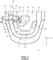
- Figure 1 shows a land vehicle 10 according to an embodiment of the invention.
- the land vehicle 10 is a rail vehicle, more preferably a tram or a streetcar.
- the land vehicle 10 is a train.
- the land vehicle 10 is a road vehicle.
- the land vehicle 10 is designed for moving along a main direction, substantially horizontal.
- an orthonormal basis (X, Y, Z), associated with the land vehicle 10 is considered.
- X represents the main direction, considered horizontal, and Z represents the vertical direction.
- the land vehicle 10 comprises a windshield 12, forming a front of the land vehicle, and a driving cabin 14, partly delimited by the windshield.
- the driving cabin 14 comprises : a floor 15 ; a control panel 16 ; a driver seat 18 ; and lateral structures 20.
- the control panel 16 is disposed at a front of the driving cabin 14.
- the control panel 16 is substantially C-shaped with a central panel 22 and lateral panels 24.
- the driver seat 18 is disposed behind the control panel 16, substantially aligned along X with the central panel 22.
- the driver seat 18 is attached to the floor 15.
- the driver seat 18 is able to rotate relative to the floor 15 around a vertical axis.
- the lateral structures 20 laterally delimit the driving cabin 14.
- the lateral structures 20 are disposed below lateral parts 26 of the windshield.
- An exit path 28 of the driving cabin 14 for the driver is formed between the driver seat 18 and at least one of the lateral structures 20.
- At least one of the lateral structures 20 includes a structural unit 30, said structural unit comprising a support structure 32 and a seat device 34.
- the structural unit 30 is substantially placed behind one of the lateral panels 24 of the control panel.
- the structural unit 30 also comprises : a maintaining element 36 ; a first 38 and a second 40 interlocking organs ; and a third 42 and a fourth 44 interlocking organs.
- the support structure 32 is fixed to the floor 15 and comprises an upper surface 46, a lateral surface 48 and a first edge 50.
- the upper surface 46 is substantially horizontal.
- the lateral surface 48 is substantially vertical and extends from the floor 15. The upper 46 and lateral 48 surfaces are joined by the first edge 50.
- the lateral surface 48 comprises a recess 52 disposed at a non-zero vertical distance from the first edge 50.
- the seat device 34 comprises a first 54 and a second 56 sitting elements.
- the seat device 34 also comprises a hinge 57.
- the first sitting element 54 is fixed to the upper surface 46 of the support structure and forms a substantially horizontal first sitting surface 58, partially delimited by the first edge 50 of the support structure 32.
- a height along Z of the lateral surface 48 of the support structure is selected according to the sitting position of a user on the first sitting surface 58.
- the second sitting element 56 is substantially flat and comprises a first face, forming a second sitting surface 60, and a second, opposed face.
- the second sitting element 56 also comprises a second 62, a third 63 and a fourth 64 edges, substantially linear, delimiting the second sitting surface 60, said second sitting surface 60 being substantially triangular.
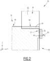
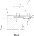
- the second sitting element 56 is pivotally assembled to the first edge 50 of the support structure 32. More precisely, the second sitting element 56 is rotatable relative to the support structure 32 between a folded configuration, shown on Figure 2 , and an unfolded configuration, shown on Figures 1 and 3 .
- the second sitting surface 60 is disposed substantially vertically, parallel to the lateral surface 48 of the support structure 32.
- the second sitting surface 60 is substantially horizontal and continuous with the first sitting surface 58, the first and second sitting surfaces forming a sitting area 68.
- the hinge 57 is assembled to the second edge 62 of the second sitting element 56 and to the first edge 50 of the support structure 32, so that the second sitting element 56 is pivotally assembled to the first edge 50.
- the third 63 and the fourth 64 edges of the second sitting element 56 form an angle ⁇ comprised between 80° and 120°, preferably comprised between 90° and 110°.
- both the third 63 and the fourth 64 edges are disposed above the floor 15.
- a user may place each of his/her legs above one of the third 63 and fourth 64 edges for an ergonomic sitting position.
- the maintaining element 36 is designed for maintaining the second sitting element 56 in the unfolded configuration.
- the maintaining element 36 is slidably assembled to the support structure 32 between a retracted position and a deployed position visible on Figure 3 .
- the maintaining element 36 comprises an arm 70 and sliding means 72.
- the arm 70 extends along a main axis 74 between a first end 76 and a second end.
- the maintaining element 36 also comprises a cavity 78 arranged in the support structure 32 and opening on the lateral surface 48.
- the sliding means 72 allow the arm 70 to slide in the cavity 78 along the main axis 74, between the retracted and deployed positions.
- the first end 76 of the arm comprises gripping means (not shown), such as a slot, to allow a user to extract the arm from the cavity.
- gripping means such as a slot
- the first end 76 of the arm 70 is received in the cavity 78. More precisely, in the retracted position, the first end 76 of the arm and the opening of the cavity 78 are covered by the second sitting element 56 in the folded configuration.
- the arm 70 bears a weight of the second sitting element 56 in the unfolded configuration.
- the second sitting element 56 also comprises a support block 80 fixed to its second face and forming a protrusion relative to said second face.
- the first end 76 of the arm 70 is in contact with the support block 80.
- the support block 80 is disposed in the recess 52 of the lateral surface 48 (not shown on the Figures). The support block 80 allows the placement of the maintaining element 36 at a suitable vertical distance from the upper surface 46 of the support structure 32.
- the first 38 and second 40 interlocking organs are situated respectively on the second sitting element 56 and on the maintaining element 36. Said first and second interlocking organs are able to cooperate for fixing the second sitting element 56 in the unfolded configuration to the maintaining element 36 in the deployed position. The security of a user seated in the sitting area 68, during movement of the land vehicle 10, is thus ensured.
- first 38 and second 40 interlocking organs are situated respectively on the support block 80 and on the first end 76 of the arm 70.
- first 38 and second 40 interlocking organs are two parts of a mechanical lock, actuatable by a user.
- the third 42 and the fourth 44 interlocking organs are situated respectively on the second sitting element 56 and on the lateral surface 48 of the support structure.
- the third and fourth interlocking organs are able to cooperate for fixing the second sitting element in the folded configuration to the lateral surface 48.
- the second sitting element 56 in the folded configuration is thus maintained during movement of the land vehicle 10, for a better security in the driving cabin 14.
- the third 42 and fourth 44 interlocking organs are two magnets, or a magnet and a ferromagnetic element.
- the magnetic strength between the two elements 42,44 is selected so that a user can unfold the second sitting element 56 by hand.
- the seat device 34 also comprises a backrest element 82, fixed to the support structure 32.
- a method for using the structural unit 30 described above will now be detailed.
- the second sitting element 56 of the structural unit 30 is in the folded configuration, so that circulation in the exit path 28 is not impaired.
- another user such as a co-driver or passenger, rotates the second sitting element 56 to the unfolded configuration, separating the third 42 and fourth 44 interlocking organs from each other.
- the user draws the arm 70 out of the cavity 78, until the first end 76 of the arm is in contact with the support block 80.
- the user then actuates the first 38 and second 40 interlocking organs, before settling on the sitting area 68.
- the sitting area 68 is configured so that the user's field of view includes the control panel 16. More preferably, the sitting area 68 is configured so that the user's face is oriented toward the control panel 16, at least toward the central panel 22 and/or the lateral panel 24 opposed to the structural unit 30. Such a configuration is attainable due to the triangular shape of the second sitting element 56, allowing the user to place his/her legs above one of the third 63 and fourth 64 edges. A median plane of the user in the sitting position is thus inclined relative to a transversal direction Y, of an angle preferably superior to 15°.
- the user disengages the first 38 and second 40 interlocking organs from each other; and pushes the arm 70 back into the cavity 78.
- the second sitting element 56 is then rotated so that the third 42 and the fourth 44 interlocking organs engage with each other.
- the opening of the cavity 78 and the first end 76 of the arm are then covered by the second sitting element 56.
- the exit path 28 of the driving cabin 14 is then liberated, allowing the driver to leave the driver seat 18 and to get out of the driving cabin 14.
Landscapes
- Engineering & Computer Science (AREA)
- Aviation & Aerospace Engineering (AREA)
- Transportation (AREA)
- Mechanical Engineering (AREA)
- Seats For Vehicles (AREA)
Abstract

Description
- The present invention relates to a structural unit for a land vehicle, comprising a seat device and a support structure, the support structure comprising an upper surface, substantially horizontal, and a lateral surface, extending substantially vertically, the upper and lateral surfaces being joined by a first edge of the support structure ; the seat device comprising a first and a second sitting elements, the first sitting element being fixed to the upper surface of the support structure and forming a substantially horizontal first sitting surface ; the second sitting element comprising a second sitting surface.
- In particular, the present invention relates to a structural unit comprising an additional seat for a driving cabin.
- It is known to provide such an additional seat to a driving cabin, as disclosed in document
DE102015208351 . As the available space in the driving cabin is usually scarce, it is known to provide the additional seat as a foldable seat. - Such an additional seat may be used by a co-driver, assisting the driver in the driving operations and/or being trained by the driver. As such, it is advantageous to provide an ergonomic additional seat, allowing a sufficient view of the control panels of the driving cabin, without blocking an exit path of the cabin.
- The present invention aims to solve the above-mentioned problems. For this purpose, the invention relates to a structural unit of the aforementioned type, wherein the second sitting element is pivotally assembled to the first edge of the support structure between a folded and an unfolded configurations, so that, in the folded configuration, the second sitting surface is substantially parallel to the lateral surface of the support structure; and in the unfolded configuration, the second sitting surface is substantially horizontal and continuous with the first sitting surface, the first and second sitting surfaces forming a sitting area.
- According to preferred embodiments, the structural unit may include one or more of the following features, considered alone or in any technically possible combination:
- the structural unit also comprises a maintaining element slidably assembled to the support structure between a retracted and a deployed positions, so that, in the deployed position, the maintaining element bears a weight of the second sitting element of the seat device in the unfolded configuration ;
- the maintaining element comprises : a cavity arranged in the support structure and opening on the lateral surface ; and an arm able to slide in the cavity between the retracted and the deployed positions, so that, in the deployed position, an end of the arm is in contact with the second sitting element;
- the structural unit also comprises a first and a second interlocking organs, situated respectively on the second sitting element of the seat device and on the maintaining element, said first and second interlocking organs being able to fix the second sitting element in the unfolded configuration to the maintaining element in the deployed position ;
- the structural unit also comprises a third and a fourth interlocking organs, situated respectively on the second sitting element of the seat device and on the lateral surface of the support structure, said third and fourth interlocking organs being able to fix the second sitting element in the folded configuration to the lateral surface ;
- the second sitting element comprises a second edge, substantially linear, and wherein the seat device comprises a hinge assembled to said second edge and to the first edge of the support structure, so that the second sitting element is pivotally assembled to the first edge ;
- the second sitting element comprises a third and a fourth edges, substantially linear and forming an angle comprised between 80° and 120° ;
- the seat device also comprises a backrest element, fixed to the support structure.
- The invention also relates to a land vehicle comprising a driving cabin, the driving cabin comprising a control panel and a driver seat, the driving cabin also comprising a structural unit as described above.
- According to a preferred embodiment, the structural unit is situated on a lateral structure of the driving cabin.
- The invention will be easier to understand in view of the following description, provided solely as an example, and with reference to the appended drawings, wherein :
-
Figure 1 is a schematic top view of a land vehicle comprising a structural unit according to an embodiment of the invention ; and -
Figure 2 andFigure 3 are cross-sectional views of the structural unit ofFigure 1 . -
Figure 1 shows aland vehicle 10 according to an embodiment of the invention. Preferably, theland vehicle 10 is a rail vehicle, more preferably a tram or a streetcar. Alternatively, theland vehicle 10 is a train. According to another embodiment, theland vehicle 10 is a road vehicle. - The
land vehicle 10 is designed for moving along a main direction, substantially horizontal. In the following description, an orthonormal basis (X, Y, Z), associated with theland vehicle 10, is considered. X represents the main direction, considered horizontal, and Z represents the vertical direction. - In the following description, the terms "front", "back", "behind", "lateral"... are understood relative to the main direction X.
- The
land vehicle 10 comprises awindshield 12, forming a front of the land vehicle, and a drivingcabin 14, partly delimited by the windshield. - The
driving cabin 14 comprises : afloor 15 ; acontrol panel 16 ; adriver seat 18 ; andlateral structures 20. - The
control panel 16 is disposed at a front of the drivingcabin 14. In the embodiment ofFigure 1 , thecontrol panel 16 is substantially C-shaped with acentral panel 22 andlateral panels 24. - The
driver seat 18 is disposed behind thecontrol panel 16, substantially aligned along X with thecentral panel 22. Preferably, thedriver seat 18 is attached to thefloor 15. For example, thedriver seat 18 is able to rotate relative to thefloor 15 around a vertical axis. - The
lateral structures 20 laterally delimit thedriving cabin 14. For example, thelateral structures 20 are disposed belowlateral parts 26 of the windshield. - An
exit path 28 of thedriving cabin 14 for the driver is formed between thedriver seat 18 and at least one of thelateral structures 20. - At least one of the
lateral structures 20 includes astructural unit 30, said structural unit comprising asupport structure 32 and aseat device 34. Thestructural unit 30 is substantially placed behind one of thelateral panels 24 of the control panel. - In the disclosed embodiment, the
structural unit 30 also comprises : a maintainingelement 36 ; a first 38 and a second 40 interlocking organs ; and a third 42 and a fourth 44 interlocking organs. - The
support structure 32 is fixed to thefloor 15 and comprises anupper surface 46, alateral surface 48 and afirst edge 50. Theupper surface 46 is substantially horizontal. Thelateral surface 48 is substantially vertical and extends from thefloor 15. The upper 46 and lateral 48 surfaces are joined by thefirst edge 50. - In the disclosed embodiment, as shown on
Figures 2 and3 , thelateral surface 48 comprises arecess 52 disposed at a non-zero vertical distance from thefirst edge 50. - The
seat device 34 comprises a first 54 and a second 56 sitting elements. In the disclosed embodiment, theseat device 34 also comprises ahinge 57. - The
first sitting element 54 is fixed to theupper surface 46 of the support structure and forms a substantially horizontalfirst sitting surface 58, partially delimited by thefirst edge 50 of thesupport structure 32. Preferably, a height along Z of thelateral surface 48 of the support structure is selected according to the sitting position of a user on thefirst sitting surface 58. - The
second sitting element 56 is substantially flat and comprises a first face, forming asecond sitting surface 60, and a second, opposed face. In the disclosed embodiment, thesecond sitting element 56 also comprises asecond 62, a third 63 and a fourth 64 edges, substantially linear, delimiting thesecond sitting surface 60, saidsecond sitting surface 60 being substantially triangular. - The
second sitting element 56 is pivotally assembled to thefirst edge 50 of thesupport structure 32. More precisely, thesecond sitting element 56 is rotatable relative to thesupport structure 32 between a folded configuration, shown onFigure 2 , and an unfolded configuration, shown onFigures 1 and3 . - In the folded configuration, the
second sitting surface 60 is disposed substantially vertically, parallel to thelateral surface 48 of thesupport structure 32. - In the unfolded configuration, the
second sitting surface 60 is substantially horizontal and continuous with thefirst sitting surface 58, the first and second sitting surfaces forming asitting area 68. - In the disclosed embodiment, the
hinge 57 is assembled to thesecond edge 62 of thesecond sitting element 56 and to thefirst edge 50 of thesupport structure 32, so that thesecond sitting element 56 is pivotally assembled to thefirst edge 50. - In the disclosed embodiment, the third 63 and the fourth 64 edges of the
second sitting element 56 form an angle α comprised between 80° and 120°, preferably comprised between 90° and 110°. In the unfolded configuration, both the third 63 and the fourth 64 edges are disposed above thefloor 15. As detailed below, a user may place each of his/her legs above one of the third 63 and fourth 64 edges for an ergonomic sitting position. - The maintaining
element 36 is designed for maintaining thesecond sitting element 56 in the unfolded configuration. - The maintaining
element 36 is slidably assembled to thesupport structure 32 between a retracted position and a deployed position visible onFigure 3 . - Preferably, the maintaining
element 36 comprises anarm 70 and sliding means 72. Thearm 70 extends along amain axis 74 between a first end 76 and a second end. - Preferably, the maintaining
element 36 also comprises acavity 78 arranged in thesupport structure 32 and opening on thelateral surface 48. The sliding means 72 allow thearm 70 to slide in thecavity 78 along themain axis 74, between the retracted and deployed positions. - Preferably, the first end 76 of the arm comprises gripping means (not shown), such as a slot, to allow a user to extract the arm from the cavity.
- In the retracted position of the maintaining
element 36, the first end 76 of thearm 70 is received in thecavity 78. More precisely, in the retracted position, the first end 76 of the arm and the opening of thecavity 78 are covered by the second sittingelement 56 in the folded configuration. - In the deployed position of the maintaining
element 36, thearm 70 bears a weight of the second sittingelement 56 in the unfolded configuration. - In the disclosed embodiment, the second sitting
element 56 also comprises asupport block 80 fixed to its second face and forming a protrusion relative to said second face. In the deployed position of the maintainingelement 36 and in the unfolded configuration of the second sittingelement 56, the first end 76 of thearm 70 is in contact with thesupport block 80. In the retracted position of the maintaining element and in the folded configuration of the second sittingelement 56, thesupport block 80 is disposed in therecess 52 of the lateral surface 48 (not shown on the Figures). Thesupport block 80 allows the placement of the maintainingelement 36 at a suitable vertical distance from theupper surface 46 of thesupport structure 32. - The first 38 and second 40 interlocking organs are situated respectively on the second sitting
element 56 and on the maintainingelement 36. Said first and second interlocking organs are able to cooperate for fixing the second sittingelement 56 in the unfolded configuration to the maintainingelement 36 in the deployed position. The security of a user seated in the sittingarea 68, during movement of theland vehicle 10, is thus ensured. - In the disclosed embodiment, the first 38 and second 40 interlocking organs are situated respectively on the
support block 80 and on the first end 76 of thearm 70. For example, the first 38 and second 40 interlocking organs are two parts of a mechanical lock, actuatable by a user. - The third 42 and the fourth 44 interlocking organs are situated respectively on the second sitting
element 56 and on thelateral surface 48 of the support structure. The third and fourth interlocking organs are able to cooperate for fixing the second sitting element in the folded configuration to thelateral surface 48. The second sittingelement 56 in the folded configuration is thus maintained during movement of theland vehicle 10, for a better security in the drivingcabin 14. - For example, the third 42 and fourth 44 interlocking organs are two magnets, or a magnet and a ferromagnetic element. The magnetic strength between the two
elements element 56 by hand. - In the disclosed embodiment, the
seat device 34 also comprises abackrest element 82, fixed to thesupport structure 32. - A method for using the
structural unit 30 described above will now be detailed. When a driver takes place into thedriver seat 18, the second sittingelement 56 of thestructural unit 30 is in the folded configuration, so that circulation in theexit path 28 is not impaired. When the driver is settled, another user, such as a co-driver or passenger, rotates the second sittingelement 56 to the unfolded configuration, separating the third 42 and fourth 44 interlocking organs from each other. The user then draws thearm 70 out of thecavity 78, until the first end 76 of the arm is in contact with thesupport block 80. The user then actuates the first 38 and second 40 interlocking organs, before settling on the sittingarea 68. - Preferably, the sitting
area 68 is configured so that the user's field of view includes thecontrol panel 16. More preferably, the sittingarea 68 is configured so that the user's face is oriented toward thecontrol panel 16, at least toward thecentral panel 22 and/or thelateral panel 24 opposed to thestructural unit 30. Such a configuration is attainable due to the triangular shape of the second sittingelement 56, allowing the user to place his/her legs above one of the third 63 and fourth 64 edges. A median plane of the user in the sitting position is thus inclined relative to a transversal direction Y, of an angle preferably superior to 15°. - After using the sitting
area 68, the user disengages the first 38 and second 40 interlocking organs from each other; and pushes thearm 70 back into thecavity 78. The second sittingelement 56 is then rotated so that the third 42 and the fourth 44 interlocking organs engage with each other. The opening of thecavity 78 and the first end 76 of the arm are then covered by the second sittingelement 56. - The
exit path 28 of the drivingcabin 14 is then liberated, allowing the driver to leave thedriver seat 18 and to get out of the drivingcabin 14.
Claims (10)
- Structural unit (30) for a land vehicle (10), comprising a seat device (34) and a support structure (32), the support structure (32) comprising an upper surface (46), substantially horizontal, and a lateral surface (48), extending substantially vertically, the upper and lateral surfaces being joined by a first edge (50) of the support structure (32) ;the seat device (34) comprising a first (54) and a second (56) sitting elements, the first sitting element (54) being fixed to the upper surface (46) of the support structure (32) and forming a substantially horizontal first sitting surface (58) ;the second sitting element (56) comprising a second sitting surface (60),the structural unit (30) being characterized in that the second sitting element (56) is pivotally assembled to the first edge (50) of the support structure (32) between a folded and an unfolded configurations,so that, in the folded configuration, the second sitting surface (60) is substantially parallel to the lateral surface (48) of the support structure (32); and in the unfolded configuration, the second sitting surface (60) is substantially horizontal and continuous with the first sitting surface (58), the first (58) and second (60) sitting surfaces forming a sitting area (68).
- Structural unit (30) according to claim 1, also comprising a maintaining element (36) slidably assembled to the support structure (32) between a retracted and a deployed positions, so that, in the deployed position, the maintaining element (36) bears a weight of the second sitting element (56) of the seat device (34) in the unfolded configuration.
- Structural unit (30) according to claim 2, wherein the maintaining element (36) comprises : a cavity (78) arranged in the support structure (32) and opening on the lateral surface (48) ; and an arm (70) able to slide in the cavity (78) between the retracted and the deployed positions, so that, in the deployed position, an end (76) of the arm (70) is in contact with the second sitting element (56).
- Structural unit (30) according to claim 2 or 3, also comprising a first (38) and a second (40) interlocking organs, situated respectively on the second sitting element (56) of the seat device (34) and on the maintaining element (36), said first and second interlocking organs being able to fix the second sitting element (56) in the unfolded configuration to the maintaining element (36) in the deployed position.
- Structural unit (30) according to one of the preceding claims, also comprising a third (42) and a fourth (44) interlocking organs, situated respectively on the second sitting element (56) of the seat device and on the lateral surface (48) of the support structure (32), said third and fourth interlocking organs being able to fix the second sitting element (56) in the folded configuration to the lateral surface (48).
- Structural unit (30) according to one of the preceding claims, wherein the second sitting element (56) comprises a second edge (62), substantially linear, and wherein the seat device (34) comprises a hinge (57) assembled to said second edge (62) and to the first edge (50) of the support structure (32), so that the second sitting element (56) is pivotally assembled to the first edge (50).
- Structural unit (30) according to one of the preceding claims, wherein the second sitting element (56) comprises a third (63) and a fourth (64) edges, substantially linear and forming an angle (α) comprised between 80° and 120°.
- Structural unit (30) according to one of the preceding claims, wherein the seat device (34) also comprises a backrest element (82), fixed to the support structure (32).
- Land vehicle (10) comprising a driving cabin (14), the driving cabin (14) comprising a control panel (16) and a driver seat (18), the driving cabin (14) also comprising a structural unit (30) according to one of the preceding claims.
- Land vehicle (10) according to claim 9, wherein the structural unit (30) is situated on a lateral structure (20) of the driving cabin (14).
Priority Applications (1)
| Application Number | Priority Date | Filing Date | Title |
|---|---|---|---|
| EP23305917.9A EP4474212B1 (en) | 2023-06-08 | 2023-06-08 | Structural unit for a land vehicle, with foldable seat |
Applications Claiming Priority (1)
| Application Number | Priority Date | Filing Date | Title |
|---|---|---|---|
| EP23305917.9A EP4474212B1 (en) | 2023-06-08 | 2023-06-08 | Structural unit for a land vehicle, with foldable seat |
Publications (2)
| Publication Number | Publication Date |
|---|---|
| EP4474212A1 true EP4474212A1 (en) | 2024-12-11 |
| EP4474212B1 EP4474212B1 (en) | 2026-03-18 |
Family
ID=87060371
Family Applications (1)
| Application Number | Title | Priority Date | Filing Date |
|---|---|---|---|
| EP23305917.9A Active EP4474212B1 (en) | 2023-06-08 | 2023-06-08 | Structural unit for a land vehicle, with foldable seat |
Country Status (1)
| Country | Link |
|---|---|
| EP (1) | EP4474212B1 (en) |
Citations (2)
| Publication number | Priority date | Publication date | Assignee | Title |
|---|---|---|---|---|
| FR2818208A1 (en) * | 2000-12-18 | 2002-06-21 | Peugeot Citroen Automobiles Sa | Arrangement of seats, for vehicle, has rear seat consisting of seat, which is located in housing formed on floor, and back, which is hinged to floor to fold forwards on to seat to provide extension to floor. |
| DE102015208351A1 (en) | 2015-05-06 | 2016-11-10 | Bombardier Transportation Gmbh | An assembly comprising a seat assembly and a support for the seat assembly for placement in a rail vehicle, method for transferring the seat assembly from a stowed position to a use position, and a rail vehicle having at least one assembly |
-
2023
- 2023-06-08 EP EP23305917.9A patent/EP4474212B1/en active Active
Patent Citations (2)
| Publication number | Priority date | Publication date | Assignee | Title |
|---|---|---|---|---|
| FR2818208A1 (en) * | 2000-12-18 | 2002-06-21 | Peugeot Citroen Automobiles Sa | Arrangement of seats, for vehicle, has rear seat consisting of seat, which is located in housing formed on floor, and back, which is hinged to floor to fold forwards on to seat to provide extension to floor. |
| DE102015208351A1 (en) | 2015-05-06 | 2016-11-10 | Bombardier Transportation Gmbh | An assembly comprising a seat assembly and a support for the seat assembly for placement in a rail vehicle, method for transferring the seat assembly from a stowed position to a use position, and a rail vehicle having at least one assembly |
Also Published As
| Publication number | Publication date |
|---|---|
| EP4474212B1 (en) | 2026-03-18 |
Similar Documents
| Publication | Publication Date | Title |
|---|---|---|
| EP2690016B1 (en) | Sliding flight attendant seat | |
| RU2340477C2 (en) | Method for vehicle interior space transformation and seat for this method realisation | |
| CN103223882B (en) | Vehicle crewstation seat assembly | |
| US7240950B2 (en) | Seat that is retractable into the floor | |
| RU2357877C2 (en) | Seat for lorry with overturn surface for seating | |
| US8485486B2 (en) | Mounting device for a retractable display | |
| US20080185893A1 (en) | Vehicle seat system | |
| US6474737B1 (en) | Variable configuration automobile vehicle seat | |
| US9463725B2 (en) | Comfort headrest | |
| CN103786884A (en) | Aircraft monument comprising an integrated cabin attendant seat and aircraft area | |
| CA2873758A1 (en) | Reconfigurable passenger restraint | |
| JP2016216032A (en) | Vehicle seat mounting device | |
| US10953778B2 (en) | Armrest and seat arrangement for a vehicle | |
| DE102008036253B4 (en) | Integrated child seat with special functions | |
| EP4474212B1 (en) | Structural unit for a land vehicle, with foldable seat | |
| EP0736412A1 (en) | Multi-position rear seat for a vehicle | |
| US8851568B2 (en) | Retractable passenger seat | |
| DE102014205457B4 (en) | Headrest for a vehicle seat | |
| EP1878609A2 (en) | Wheelchair accomodation in vehicles | |
| EP1574390B1 (en) | Vehicle, in particular a commercial vehicle, with a collapsible front passenger seat | |
| KR20210129968A (en) | Roof Lining having Muti-function Plate | |
| EP3514064A1 (en) | Aircraft passenger seat extended armrest | |
| WO2003055716A1 (en) | Motor vehicle seat, with a knee-rest element | |
| CN109532687A (en) | Accessory tray for vehicle | |
| EP3362022B1 (en) | Deflector plate device for a public transport vehicle |
Legal Events
| Date | Code | Title | Description |
|---|---|---|---|
| PUAI | Public reference made under article 153(3) epc to a published international application that has entered the european phase |
Free format text: ORIGINAL CODE: 0009012 |
|
| STAA | Information on the status of an ep patent application or granted ep patent |
Free format text: STATUS: THE APPLICATION HAS BEEN PUBLISHED |
|
| STAA | Information on the status of an ep patent application or granted ep patent |
Free format text: STATUS: REQUEST FOR EXAMINATION WAS MADE |
|
| AK | Designated contracting states |
Kind code of ref document: A1 Designated state(s): AL AT BE BG CH CY CZ DE DK EE ES FI FR GB GR HR HU IE IS IT LI LT LU LV MC ME MK MT NL NO PL PT RO RS SE SI SK SM TR |
|
| 17P | Request for examination filed |
Effective date: 20241122 |
|
| RBV | Designated contracting states (corrected) |
Designated state(s): AL AT BE BG CH CY CZ DE DK EE ES FI FR GB GR HR HU IE IS IT LI LT LU LV MC ME MK MT NL NO PL PT RO RS SE SI SK SM TR |
|
| GRAP | Despatch of communication of intention to grant a patent |
Free format text: ORIGINAL CODE: EPIDOSNIGR1 |
|
| STAA | Information on the status of an ep patent application or granted ep patent |
Free format text: STATUS: GRANT OF PATENT IS INTENDED |
|
| INTG | Intention to grant announced |
Effective date: 20251030 |
|
| GRAS | Grant fee paid |
Free format text: ORIGINAL CODE: EPIDOSNIGR3 |
|
| GRAA | (expected) grant |
Free format text: ORIGINAL CODE: 0009210 |
|
| STAA | Information on the status of an ep patent application or granted ep patent |
Free format text: STATUS: THE PATENT HAS BEEN GRANTED |
|
| AK | Designated contracting states |
Kind code of ref document: B1 Designated state(s): AL AT BE BG CH CY CZ DE DK EE ES FI FR GB GR HR HU IE IS IT LI LT LU LV MC ME MK MT NL NO PL PT RO RS SE SI SK SM TR |
|
| REG | Reference to a national code |
Ref country code: CH Ref legal event code: F10 Free format text: ST27 STATUS EVENT CODE: U-0-0-F10-F00 (AS PROVIDED BY THE NATIONAL OFFICE) Effective date: 20260318 Ref country code: GB Ref legal event code: FG4D |
|
| REG | Reference to a national code |
Ref country code: CH Ref legal event code: R17 Free format text: ST27 STATUS EVENT CODE: U-0-0-R10-R17 (AS PROVIDED BY THE NATIONAL OFFICE) Effective date: 20260320 |
|
| REG | Reference to a national code |
Ref country code: DE Ref legal event code: R096 Ref document number: 602023013686 Country of ref document: DE |
|
| REG | Reference to a national code |
Ref country code: IE Ref legal event code: FG4D |
|
| P01 | Opt-out of the competence of the unified patent court (upc) registered |
Free format text: CASE NUMBER: UPC_APP_0011070_4474212/2026 Effective date: 20260327 |