EP4474102A1 - A cutting or a cutting-splitting machine with a safety assembly for preventing incorrect use - Google Patents
A cutting or a cutting-splitting machine with a safety assembly for preventing incorrect use Download PDFInfo
- Publication number
- EP4474102A1 EP4474102A1 EP24180795.7A EP24180795A EP4474102A1 EP 4474102 A1 EP4474102 A1 EP 4474102A1 EP 24180795 A EP24180795 A EP 24180795A EP 4474102 A1 EP4474102 A1 EP 4474102A1
- Authority
- EP
- European Patent Office
- Prior art keywords
- cutting
- sensor
- rotations
- safety assembly
- machine
- Prior art date
- Legal status (The legal status is an assumption and is not a legal conclusion. Google has not performed a legal analysis and makes no representation as to the accuracy of the status listed.)
- Pending
Links
Images

Classifications
-
- B—PERFORMING OPERATIONS; TRANSPORTING
- B23—MACHINE TOOLS; METAL-WORKING NOT OTHERWISE PROVIDED FOR
- B23Q—DETAILS, COMPONENTS, OR ACCESSORIES FOR MACHINE TOOLS, e.g. ARRANGEMENTS FOR COPYING OR CONTROLLING; MACHINE TOOLS IN GENERAL CHARACTERISED BY THE CONSTRUCTION OF PARTICULAR DETAILS OR COMPONENTS; COMBINATIONS OR ASSOCIATIONS OF METAL-WORKING MACHINES, NOT DIRECTED TO A PARTICULAR RESULT
- B23Q17/00—Arrangements for observing, indicating or measuring on machine tools
- B23Q17/10—Arrangements for observing, indicating or measuring on machine tools for indicating or measuring cutting speed or number of revolutions
-
- B—PERFORMING OPERATIONS; TRANSPORTING
- B23—MACHINE TOOLS; METAL-WORKING NOT OTHERWISE PROVIDED FOR
- B23Q—DETAILS, COMPONENTS, OR ACCESSORIES FOR MACHINE TOOLS, e.g. ARRANGEMENTS FOR COPYING OR CONTROLLING; MACHINE TOOLS IN GENERAL CHARACTERISED BY THE CONSTRUCTION OF PARTICULAR DETAILS OR COMPONENTS; COMBINATIONS OR ASSOCIATIONS OF METAL-WORKING MACHINES, NOT DIRECTED TO A PARTICULAR RESULT
- B23Q11/00—Accessories fitted to machine tools for keeping tools or parts of the machine in good working condition or for cooling work; Safety devices specially combined with or arranged in, or specially adapted for use in connection with, machine tools
- B23Q11/0078—Safety devices protecting the operator, e.g. against accident or noise
- B23Q11/0092—Safety devices protecting the operator, e.g. against accident or noise actuating braking or stopping means
-
- B—PERFORMING OPERATIONS; TRANSPORTING
- B60—VEHICLES IN GENERAL
- B60K—ARRANGEMENT OR MOUNTING OF PROPULSION UNITS OR OF TRANSMISSIONS IN VEHICLES; ARRANGEMENT OR MOUNTING OF PLURAL DIVERSE PRIME-MOVERS IN VEHICLES; AUXILIARY DRIVES FOR VEHICLES; INSTRUMENTATION OR DASHBOARDS FOR VEHICLES; ARRANGEMENTS IN CONNECTION WITH COOLING, AIR INTAKE, GAS EXHAUST OR FUEL SUPPLY OF PROPULSION UNITS IN VEHICLES
- B60K17/00—Arrangement or mounting of transmissions in vehicles
- B60K17/28—Arrangement or mounting of transmissions in vehicles characterised by arrangement, location, or type of power take-off
-
- A—HUMAN NECESSITIES
- A01—AGRICULTURE; FORESTRY; ANIMAL HUSBANDRY; HUNTING; TRAPPING; FISHING
- A01B—SOIL WORKING IN AGRICULTURE OR FORESTRY; PARTS, DETAILS, OR ACCESSORIES OF AGRICULTURAL MACHINES OR IMPLEMENTS, IN GENERAL
- A01B71/00—Construction or arrangement of setting or adjusting mechanisms, of implement or tool drive or of power take-off; Means for protecting parts against dust, or the like; Adapting machine elements to or for agricultural purposes
- A01B71/06—Special adaptations of coupling means between power take-off and transmission shaft to the implement or machine
- A01B71/063—Special adaptations of coupling means between power take-off and transmission shaft to the implement or machine for enabling transmission coupling and connection between tractor and implements to be controlled from the driver's seat
Definitions
- the present invention belongs to the field of splitting and cutting-splitting machines, particularly to the field of safety devices for said machines.
- the invention relates to a cutting or a cutting-splitting machine with a safety assembly for preventing incorrect use.
- Wood is widely used for heating, but has to be suitably shaped and sized for use.
- wood trunks are cut into logs having a size and shape corresponding to fireplaces, furnaces, and stoves, so that no further cutting or splitting is necessary.
- Different wood processing devices are known, which cut and split trunks with minimal manual handling.
- Said device are for example cutting machines (circular leaf saws), cutting-splitting machines, which also comprise a leaf saw, wherein the operation of the machine may be with a tractor through a PTO shaft or with an electromotor or any other element, which ensures torque for rotation of the cutting means.
- a problem in exceeding the number of allowed rotations is particularly occurring in machines driven via the PTO shaft. Consequently, the rotation speed of the cutting means, such as the circular leaf, increases beyond allowed ranges, which represents a possibility for damaging the cutting means, other machine parts of the machine and/or user, which operates with the machine.
- One possibility is to inform the user about the ranges or maximal rotations in user guides or warning labels, however, this is not ensuring safety.
- the technical problem which is solved by the present invention, is the constructional design of safety assembly for preventing incorrect use of the cutting or the cutting-splitting machine and will in case of exceeding setting terminate operation of the machine or the cutting means.
- Patent application US2012024427A1 describes a device for processing wood comprising a motor for ensuring operation of cutting means, and a safety system arranged to sense dangerous situations, wherein said safety system comprises a controller, which can turn off the motor in case a dangerous situation is detected.
- the cutting means is a circular saw and its rotation is sensed with a system for detecting rotation, which receives discrete signs of rotation, and which is connected to the safety system, wherein signals are sent to the safety system for terminating operation of the reaction system once the cutting means stops rotating.
- Said rotation sensing is arranged to check whether the device is operating or not, wherein the operator or the user of the wood processing device is protected.
- the discrete signs of rotation may be electrical pulses, which occur in a particular number of cutting means rotation.
- the system for sensing rotation may comprise a Hall sensor arranged for detection of rotation by periodic rotation of a magnet installed on a shaft on which the cutting means is installed.
- the present invention differs from this solution in that the safety device is arranged to monitor correct operation of the machine and in case of incorrect operation turns off the machine.
- the invention is based on a splitting, cutting or cutting-splitting machine for preparation of wood comprising rotatable cutting means arranged to cut the logs.
- the technical problem of designing a safety assembly for preventing incorrect use of the cutting or cutting-splitting machine is solved as defined in the independent claim, while the preferred embodiments of the solution are defined in dependent claims.
- the cutting or the cutting-splitting machine according to the invention is equipped with a safety assembly for preventing incorrect use, which involves measurement the number of rotations on any rotatable part enabling cutting means rotation, and turning off the machine operation in case incorrect rotations have been sensed.
- the safety assembly comprises:
- the sensor may be a Hall sensor, an inductive sensor, a speed sensor or any other sensor arranged to detect or measure rotation speed and number of rotations. It may be installed on a PTO shaft, on a shaft on which the cutting means is installed, or on any intermediate element arranged to transfer torque from the PTO shaft to the cutting means.
- the safety assembly comprises the following: an arbitrary number of magnets are arbitrarily arranged on a carrying ring mounted on the shaft, so that it rotates together with the shaft.
- the ring is attached to the shaft with a screw.
- the Hall sensor is mounted, so that it can sense the magnets on the ring.
- the Hall sensor is mounted using a holder, usually on the housing of the drive. A cable or any other suitable wire connection connects the Hall sensor to the controller, so that data about sensed magnets are transferred to the controller, which consequently calculates the rotations and based on this number controls the machine.
- a possible upgrade of this system is that the machine is provided with any machine part, which is in case of incorrect rotations arranged to terminate torque transfer. This may be achieved via shutting off the PTO shaft, for example using any connection means to the tractor known to the skilled person, such as via tractor sockets or isobus connectors to the tractor.
- a second possibility is to enable shutting off with any other connection, which is arranged to simultaneously turn off rotation of the PTO shaft. Further possibilities are to shut off transfer of rotations in a mechanical, hydraulic, electric or combined manner, for example using different brakes, clutches, belt tensioning devices, chain tensioning devices, and similar components, which may terminate or interrupt torque transfer to the cutting means.
- the tensioning device is in a possible embodiment installed in any place, where the torque is transferred using a chain or belts tensioned by the said tensioning device.
- the clutch may be installed on any shaft transferring torque.
- the brake may be installed in any suitable manner to terminate operation of the cutting means in case of sensed incorrect operation. Such brakes and their installation are known. An embodiment as disclosed in patent SI 25765 is possible.
- FIG 1 shows the safety assembly 1, which comprises:
- Measurement of the number of rotations on any rotating part which enables rotation of the cutting means, is important for timely termination of machine operation in case incorrect number of sensed rotations is detected. This essentially decreases the possibility of cutting means damage, damage to other parts of the machine, and/or injuries of the user who operates the machine.
- Figure 2 shows a view of the safety assembly from the opposite side, wherein the magnets 4 are visible and their arrangement on the carrier ring 5 is shown.
- the safety assembly shown in figures 1 and 2 may be installed in a cutting or a cutting-splitting machine, in particular to the PTO shaft 7 as shown in the circular part of figure 3 .
Landscapes
- Engineering & Computer Science (AREA)
- Mechanical Engineering (AREA)
- Chemical & Material Sciences (AREA)
- Combustion & Propulsion (AREA)
- Transportation (AREA)
- Crushing And Pulverization Processes (AREA)
Abstract
The invention belongs to the field of splitting and cutting-splitting machines, particularly to the field of safety devices for said machines. The cutting or a cutting-splitting machine is provided with a safety assembly for preventing incorrect use, which comprises measurement the number of rotations on any rotatable part enabling cutting means rotation, and turning off the machine operation in case incorrect rotations have been sensed. The safety assembly comprises:
- a sensor configured to measure rotations, said sensor being installed on any rotating part,
- a control unit configured to receive information about sensed rotations from the sensor and further configured to trigger termination of machine operation in case sensed rotations are outside of a pre-set range.
- a sensor configured to measure rotations, said sensor being installed on any rotating part,
- a control unit configured to receive information about sensed rotations from the sensor and further configured to trigger termination of machine operation in case sensed rotations are outside of a pre-set range.
The sensor may be a Hall sensor, an inductive sensor, a speed sensor or any other sensor arranged to detect or measure rotation speed and the number of rotations. It may be installed on a PTO shaft, on a shaft on which the cutting means is installed, or on any intermediate element, which is arranged to transfer torque from the PTO shaft to the cutting means.
Description
- The present invention belongs to the field of splitting and cutting-splitting machines, particularly to the field of safety devices for said machines. The invention relates to a cutting or a cutting-splitting machine with a safety assembly for preventing incorrect use.
- Wood is widely used for heating, but has to be suitably shaped and sized for use. During log processing wood trunks are cut into logs having a size and shape corresponding to fireplaces, furnaces, and stoves, so that no further cutting or splitting is necessary. Different wood processing devices are known, which cut and split trunks with minimal manual handling. Said device are for example cutting machines (circular leaf saws), cutting-splitting machines, which also comprise a leaf saw, wherein the operation of the machine may be with a tractor through a PTO shaft or with an electromotor or any other element, which ensures torque for rotation of the cutting means.
- A problem in exceeding the number of allowed rotations is particularly occurring in machines driven via the PTO shaft. Consequently, the rotation speed of the cutting means, such as the circular leaf, increases beyond allowed ranges, which represents a possibility for damaging the cutting means, other machine parts of the machine and/or user, which operates with the machine. One possibility is to inform the user about the ranges or maximal rotations in user guides or warning labels, however, this is not ensuring safety.
- Therefore, the technical problem, which is solved by the present invention, is the constructional design of safety assembly for preventing incorrect use of the cutting or the cutting-splitting machine and will in case of exceeding setting terminate operation of the machine or the cutting means.
- Patent application
US2012024427A1 describes a device for processing wood comprising a motor for ensuring operation of cutting means, and a safety system arranged to sense dangerous situations, wherein said safety system comprises a controller, which can turn off the motor in case a dangerous situation is detected. According to a possible embodiment, the cutting means is a circular saw and its rotation is sensed with a system for detecting rotation, which receives discrete signs of rotation, and which is connected to the safety system, wherein signals are sent to the safety system for terminating operation of the reaction system once the cutting means stops rotating. Said rotation sensing is arranged to check whether the device is operating or not, wherein the operator or the user of the wood processing device is protected. The discrete signs of rotation may be electrical pulses, which occur in a particular number of cutting means rotation. The system for sensing rotation may comprise a Hall sensor arranged for detection of rotation by periodic rotation of a magnet installed on a shaft on which the cutting means is installed. - The present invention differs from this solution in that the safety device is arranged to monitor correct operation of the machine and in case of incorrect operation turns off the machine.
- The invention is based on a splitting, cutting or cutting-splitting machine for preparation of wood comprising rotatable cutting means arranged to cut the logs. The technical problem of designing a safety assembly for preventing incorrect use of the cutting or cutting-splitting machine is solved as defined in the independent claim, while the preferred embodiments of the solution are defined in dependent claims.
- The cutting or the cutting-splitting machine according to the invention is equipped with a safety assembly for preventing incorrect use, which involves measurement the number of rotations on any rotatable part enabling cutting means rotation, and turning off the machine operation in case incorrect rotations have been sensed. The safety assembly comprises:
- a sensor configured to measure rotations, said sensor being installed on any rotating part,
- a control unit configured to receive information about sensed rotations from the sensor and further configured to trigger termination of machine operation in case sensed rotations are outside of a pre-set range.
- The sensor may be a Hall sensor, an inductive sensor, a speed sensor or any other sensor arranged to detect or measure rotation speed and number of rotations. It may be installed on a PTO shaft, on a shaft on which the cutting means is installed, or on any intermediate element arranged to transfer torque from the PTO shaft to the cutting means.
- The preferred embodiment, wherein the Hall sensor is used, the safety assembly comprises the following: an arbitrary number of magnets are arbitrarily arranged on a carrying ring mounted on the shaft, so that it rotates together with the shaft. Preferably, the ring is attached to the shaft with a screw. In the vicinity of the carrying ring the Hall sensor is mounted, so that it can sense the magnets on the ring. The Hall sensor is mounted using a holder, usually on the housing of the drive. A cable or any other suitable wire connection connects the Hall sensor to the controller, so that data about sensed magnets are transferred to the controller, which consequently calculates the rotations and based on this number controls the machine.
- A possible upgrade of this system is that the machine is provided with any machine part, which is in case of incorrect rotations arranged to terminate torque transfer. This may be achieved via shutting off the PTO shaft, for example using any connection means to the tractor known to the skilled person, such as via tractor sockets or isobus connectors to the tractor. A second possibility is to enable shutting off with any other connection, which is arranged to simultaneously turn off rotation of the PTO shaft. Further possibilities are to shut off transfer of rotations in a mechanical, hydraulic, electric or combined manner, for example using different brakes, clutches, belt tensioning devices, chain tensioning devices, and similar components, which may terminate or interrupt torque transfer to the cutting means. The tensioning device is in a possible embodiment installed in any place, where the torque is transferred using a chain or belts tensioned by the said tensioning device. The clutch may be installed on any shaft transferring torque. The brake may be installed in any suitable manner to terminate operation of the cutting means in case of sensed incorrect operation. Such brakes and their installation are known. An embodiment as disclosed in patent
SI 25765 - In this case, even if the user sets the rotations on the PTO shaft too high (outside of the allowed range), the rotations are not transferred to other driven parts, such as the cutting means or hydraulic pump, as the drive connection will be interrupted.
- The invention will be described in further detail based on exemplary embodiment and figures, which show:
- Figure 1
- The safety assembly for measuring rotation
- Figure 2
- The safety assembly for measuring rotation from the opposite side, wherein a possible arrangement of magnets on the carrier ring is shown
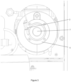
- Figure 3
- The cutting machine with the safety assembly, wherein the rotation sensor is installed on the PTO shaft
-
Figure 1 shows thesafety assembly 1, which comprises: - a
Hall sensor 2 for measuring rotation installed on aholder 3, which is arranged for installation on a housing of the machine drive near thedrive shaft 7, via which the torque is transferred to the cutting means of the machine, - a cable or a
wire connection 6 for connecting theHall sensor 2 with the control unit (not shown) via aconnector 8, -
magnets 4 installed on acarrier ring 5, which is with a screw 9 mounted on theshaft 7, so that it rotates together with theshaft 7, wherein saidmagnets 4 may be sensed by theHall sensor 2 to determine the rotation speed of the shaft, and - a control unit arranged to receive information about sensed rotations from the sensor and further configured to trigger termination of machine operation in case sensed rotations are outside of a pre-set range.
- Measurement of the number of rotations on any rotating part, which enables rotation of the cutting means, is important for timely termination of machine operation in case incorrect number of sensed rotations is detected. This essentially decreases the possibility of cutting means damage, damage to other parts of the machine, and/or injuries of the user who operates the machine.
-
Figure 2 shows a view of the safety assembly from the opposite side, wherein themagnets 4 are visible and their arrangement on thecarrier ring 5 is shown. - The safety assembly shown in
figures 1 and 2 may be installed in a cutting or a cutting-splitting machine, in particular to thePTO shaft 7 as shown in the circular part offigure 3 .
Claims (12)
- A cutting or a cutting-splitting machine with a safety assembly for preventing incorrect use, comprising a step of measurement of number of rotations on any rotatable part, which enables rotation of cutting means, and termination of machine operation in case of unsuitable number of sensed rotations, wherein said safety assembly comprises:- a sensor configured to measure rotations, said sensor being installed on any rotating part,- a control unit configured to receive information about sensed rotations from the sensor and further configured to trigger termination of machine operation in case sensed rotations are outside of a pre-set range.
- The cutting or a cutting-splitting machine with a safety assembly for preventing incorrect use according to claim 1, wherein the sensor is selected in the group comprising a Hall sensor (2), an inductive sensor, a speed sensor or any other sensor arranged to sense or measure speed of rotation and number of rotations.
- The cutting or a cutting-splitting machine with a safety assembly for preventing incorrect use according to claim 1 or claim 2, wherein the sensor is installed on the PTO shaft, on a shaft on which the cutting means is installed, or on any other intermediate element, which is arranged to transfer the torque from the PTO shaft to the cutting means.
- The cutting or a cutting-splitting machine with a safety assembly for preventing incorrect use according to claim 2 or claim 3, wherein the sensor is a Hall sensor (2).
- The cutting or a cutting-splitting machine with a safety assembly for preventing incorrect use according to the preceding claim, wherein the safety device comprises the following components:- the Hall sensor (2) for measuring rotations,- a cable or a wire connection (6) to connect the Hall sensor (2) to the control unit,- magnets (4) installed on a carrier ring (5) attached to the shaft (7), so as to rotate together with the shaft (7), wherein the Hall sensor (2) is arranged to sense said magnets (4) and thus determine the rotation speed of the shaft, and- the control unit configured to receive information about sensed rotations from the sensor and further configured to trigger termination of machine operation in case sensed rotations are outside of a pre-set range.
- The cutting or a cutting-splitting machine with a safety assembly for preventing incorrect use according to the preceding claim, wherein the Hall sensor is installed on a holder (3) arranged for installation on a frame of the machine drive near the drive shaft (7), through which torque is transferred to the cutting means of the machine.
- The cutting or a cutting-splitting machine with a safety assembly for preventing incorrect use according to any of the preceding claims, which further comprises any machine part arranged to terminate transfer of rotations in case of detected incorrect rotations.
- The cutting or a cutting-splitting machine with a safety assembly for preventing incorrect use according to the preceding claim, wherein the rotation transfer is achieved in a mechanical, hydraulic, electric or combined manner.
- The cutting or a cutting-splitting machine with a safety assembly for preventing incorrect use according to claim 8, wherein the rotation transfer is achieved by turning off the PTO shaft via any communication connection with a tractor.
- The cutting or a cutting-splitting machine with a safety assembly for preventing incorrect use according to claim 8, wherein the rotation transfer is achieved using clutches, belt tensioning devices, chain tensioning devices, and similar components, which may terminate or interrupt torque transfer to the cutting means.
- The cutting or a cutting-splitting machine with a safety assembly for preventing incorrect use according to claim 10, wherein the rotation transfer is achieved in any location, where torque is transferred using a chain or belts tensioned by a tensioning device.
- The cutting or a cutting-splitting machine with a safety assembly for preventing incorrect use according to claim 10, wherein the rotation transfer is achieved with a brake or a clutch mounted on any shaft arranged to transfer torque.
Applications Claiming Priority (1)
| Application Number | Priority Date | Filing Date | Title |
|---|---|---|---|
| SI202300091A SI26518A (en) | 2023-06-08 | 2023-06-08 | Cutting or sawing-splitting machine with a safety assembly to prevent improper use |
Publications (1)
| Publication Number | Publication Date |
|---|---|
| EP4474102A1 true EP4474102A1 (en) | 2024-12-11 |
Family
ID=91700083
Family Applications (1)
| Application Number | Title | Priority Date | Filing Date |
|---|---|---|---|
| EP24180795.7A Pending EP4474102A1 (en) | 2023-06-08 | 2024-06-07 | A cutting or a cutting-splitting machine with a safety assembly for preventing incorrect use |
Country Status (2)
| Country | Link |
|---|---|
| EP (1) | EP4474102A1 (en) |
| SI (1) | SI26518A (en) |
Citations (8)
| Publication number | Priority date | Publication date | Assignee | Title |
|---|---|---|---|---|
| DE4239530A1 (en) * | 1992-11-25 | 1994-05-26 | Kloeckner Humboldt Deutz Ag | Variable take-off drive for agricultural tractor - uses electronic control device regulating take off shaft rotation dependent on stored characteristic |
| EP1182006A2 (en) * | 2000-08-25 | 2002-02-27 | Heckert Werkzeugmaschinen GmbH | Rotational speed monitoring, in particular for the stationary state of a tool spindle |
| US20060128524A1 (en) * | 2004-12-09 | 2006-06-15 | Jochen Busch | Drive arrangement for an agricultural working machine |
| DE102007026517A1 (en) * | 2007-06-08 | 2008-04-24 | Siemens Ag | Fast-rotating processing machine e.g. grooving machine, for processing wood piece, has drive device exhibiting converter device, which is formed with device for sensor less safety relevant monitoring of number of revolutions |
| US20090031699A1 (en) * | 2007-07-31 | 2009-02-05 | Caterpillar Inc. | Drive line torque perturbation for pto mode shifting |
| US20120024427A1 (en) | 2007-12-31 | 2012-02-02 | Gass Stephen F | Detection systems for power equipment |
| GB2486730A (en) * | 2010-12-24 | 2012-06-27 | Valtra Oy Ab | A control system for a power takeoff (PTO) stub of an agricultural tractor |
| EP3456470A2 (en) * | 2017-09-18 | 2019-03-20 | DECKEL MAHO Pfronten GmbH | System for changing and inserting or placing tools on a machine tool and machine tool equipped with such a system |
-
2023
- 2023-06-08 SI SI202300091A patent/SI26518A/en active IP Right Grant
-
2024
- 2024-06-07 EP EP24180795.7A patent/EP4474102A1/en active Pending
Patent Citations (8)
| Publication number | Priority date | Publication date | Assignee | Title |
|---|---|---|---|---|
| DE4239530A1 (en) * | 1992-11-25 | 1994-05-26 | Kloeckner Humboldt Deutz Ag | Variable take-off drive for agricultural tractor - uses electronic control device regulating take off shaft rotation dependent on stored characteristic |
| EP1182006A2 (en) * | 2000-08-25 | 2002-02-27 | Heckert Werkzeugmaschinen GmbH | Rotational speed monitoring, in particular for the stationary state of a tool spindle |
| US20060128524A1 (en) * | 2004-12-09 | 2006-06-15 | Jochen Busch | Drive arrangement for an agricultural working machine |
| DE102007026517A1 (en) * | 2007-06-08 | 2008-04-24 | Siemens Ag | Fast-rotating processing machine e.g. grooving machine, for processing wood piece, has drive device exhibiting converter device, which is formed with device for sensor less safety relevant monitoring of number of revolutions |
| US20090031699A1 (en) * | 2007-07-31 | 2009-02-05 | Caterpillar Inc. | Drive line torque perturbation for pto mode shifting |
| US20120024427A1 (en) | 2007-12-31 | 2012-02-02 | Gass Stephen F | Detection systems for power equipment |
| GB2486730A (en) * | 2010-12-24 | 2012-06-27 | Valtra Oy Ab | A control system for a power takeoff (PTO) stub of an agricultural tractor |
| EP3456470A2 (en) * | 2017-09-18 | 2019-03-20 | DECKEL MAHO Pfronten GmbH | System for changing and inserting or placing tools on a machine tool and machine tool equipped with such a system |
Also Published As
| Publication number | Publication date |
|---|---|
| SI26518A (en) | 2024-12-31 |
Similar Documents
| Publication | Publication Date | Title |
|---|---|---|
| DK1599637T3 (en) | A SYSTEM INCLUDING A TOOL DETERMINATION MECHANISM AND A WORKING TOOL | |
| US11519764B2 (en) | Rotary encoder and method for determining malfunction of a rotary encoder | |
| US8087599B2 (en) | Anti-paper jam protection device for shredders | |
| EP1900484A3 (en) | Power tool anti-kickback system with rotational rate sensor | |
| CA2733366A1 (en) | Safety system in and method for the operation of a combustion device | |
| EP3620265B1 (en) | Tool system | |
| US20020084368A1 (en) | Safety systems for grinding machines | |
| CN109443294B (en) | Angle sensor test device and angle sensor test station | |
| EP1273395A2 (en) | Target torque detection at power wrenches having mechanical release clutch | |
| EP2969424A1 (en) | Guard detection system for a power tool | |
| KR101987466B1 (en) | Life time test apparatus of encoder | |
| US9050726B2 (en) | Activation control device for robotic auxiliary devices | |
| CN101479583A (en) | Overload protection system | |
| SI26518A (en) | Cutting or sawing-splitting machine with a safety assembly to prevent improper use | |
| US20210270277A1 (en) | Method for Detecting Belt Slippage in a Belt Driven Fan System | |
| CN118284495A (en) | Rotary power tool components for torque control | |
| US12235184B2 (en) | Rotary encoder and a method for monitoring operation of the rotary encoder | |
| JP2009196302A (en) | Twin screw kneading extruder and load torque calculation method in twin screw kneading extruder | |
| US12332139B2 (en) | Rotary encoder and a method for determining malfunction of a rotary encoder | |
| US8191399B2 (en) | Monitoring device and monitoring method for a drive device | |
| KR102525068B1 (en) | Monitoring system of multi-belt | |
| CN201858179U (en) | Power fan monitoring system and lottery machine with same | |
| EP3219181B1 (en) | Operating machine | |
| KR100902554B1 (en) | Overload Protector | |
| WO1996022175A3 (en) | Safety device for electrically driven hand tools, in particular circular and compass saws |
Legal Events
| Date | Code | Title | Description |
|---|---|---|---|
| PUAI | Public reference made under article 153(3) epc to a published international application that has entered the european phase |
Free format text: ORIGINAL CODE: 0009012 |
|
| STAA | Information on the status of an ep patent application or granted ep patent |
Free format text: STATUS: THE APPLICATION HAS BEEN PUBLISHED |
|
| AK | Designated contracting states |
Kind code of ref document: A1 Designated state(s): AL AT BE BG CH CY CZ DE DK EE ES FI FR GB GR HR HU IE IS IT LI LT LU LV MC ME MK MT NL NO PL PT RO RS SE SI SK SM TR |
|
| STAA | Information on the status of an ep patent application or granted ep patent |
Free format text: STATUS: REQUEST FOR EXAMINATION WAS MADE |
|
| 17P | Request for examination filed |
Effective date: 20250606 |