EP4474074A1 - Method of manufacturing a component - Google Patents
Method of manufacturing a component Download PDFInfo
- Publication number
- EP4474074A1 EP4474074A1 EP24175733.5A EP24175733A EP4474074A1 EP 4474074 A1 EP4474074 A1 EP 4474074A1 EP 24175733 A EP24175733 A EP 24175733A EP 4474074 A1 EP4474074 A1 EP 4474074A1
- Authority
- EP
- European Patent Office
- Prior art keywords
- mould
- unit
- initial
- angular orientation
- seed
- Prior art date
- Legal status (The legal status is an assumption and is not a legal conclusion. Google has not performed a legal analysis and makes no representation as to the accuracy of the status listed.)
- Granted
Links
Images





Classifications
-
- B—PERFORMING OPERATIONS; TRANSPORTING
- B22—CASTING; POWDER METALLURGY
- B22C—FOUNDRY MOULDING
- B22C7/00—Patterns; Manufacture thereof so far as not provided for in other classes
- B22C7/02—Lost patterns
-
- B—PERFORMING OPERATIONS; TRANSPORTING
- B22—CASTING; POWDER METALLURGY
- B22C—FOUNDRY MOULDING
- B22C9/00—Moulds or cores; Moulding processes
- B22C9/02—Sand moulds or like moulds for shaped castings
- B22C9/04—Use of lost patterns
-
- B—PERFORMING OPERATIONS; TRANSPORTING
- B22—CASTING; POWDER METALLURGY
- B22C—FOUNDRY MOULDING
- B22C9/00—Moulds or cores; Moulding processes
- B22C9/02—Sand moulds or like moulds for shaped castings
- B22C9/04—Use of lost patterns
- B22C9/043—Removing the consumable pattern
-
- B—PERFORMING OPERATIONS; TRANSPORTING
- B22—CASTING; POWDER METALLURGY
- B22C—FOUNDRY MOULDING
- B22C9/00—Moulds or cores; Moulding processes
- B22C9/22—Moulds for peculiarly-shaped castings
- B22C9/24—Moulds for peculiarly-shaped castings for hollow articles
-
- B—PERFORMING OPERATIONS; TRANSPORTING
- B22—CASTING; POWDER METALLURGY
- B22D—CASTING OF METALS; CASTING OF OTHER SUBSTANCES BY THE SAME PROCESSES OR DEVICES
- B22D25/00—Special casting characterised by the nature of the product
- B22D25/06—Special casting characterised by the nature of the product by its physical properties
-
- B—PERFORMING OPERATIONS; TRANSPORTING
- B22—CASTING; POWDER METALLURGY
- B22D—CASTING OF METALS; CASTING OF OTHER SUBSTANCES BY THE SAME PROCESSES OR DEVICES
- B22D27/00—Treating the metal in the mould while it is molten or ductile ; Pressure or vacuum casting
- B22D27/20—Measures not previously mentioned for influencing the grain structure or texture; Selection of compositions therefor
-
- B—PERFORMING OPERATIONS; TRANSPORTING
- B22—CASTING; POWDER METALLURGY
- B22D—CASTING OF METALS; CASTING OF OTHER SUBSTANCES BY THE SAME PROCESSES OR DEVICES
- B22D27/00—Treating the metal in the mould while it is molten or ductile ; Pressure or vacuum casting
- B22D27/04—Influencing the temperature of the metal, e.g. by heating or cooling the mould
- B22D27/045—Directionally solidified castings
Definitions
- the present disclosure relates to a gas turbine engine, and a method of manufacturing a component that may be associated with the gas turbine engine.
- Certain articles and components are preferably formed with known crystallography in order to achieve desired operational performance.
- a desired crystallography may allow the components to be more resistant to high temperature creep.
- a number of methods have been identified for forming single crystal components. Such methods generally utilise a seed crystal to initiate crystal formation in the component within a mould. What is generally required is a mechanism to ensure that the desired crystallography is achieved.
- conventional methods have disadvantages in attempting to successfully circumvent hazards with respect to stray grain nucleation in growth.
- stray grains in single crystal castings are detrimental and needs to be avoided, which requires a very tight specification to being adhered to.
- Such stray grains are typically located proximate to a surface of the cast component. Further, the stray grains in such regions invariably bear an orientation relationship with the primary single crystal grain and are not randomly nucleated.
- a method of manufacturing a component includes forming a mould assembly including a central sprue extending along a central axis and an initial mould unit including a wax pattern and a seed section connected to the wax pattern.
- the wax pattern is made of a wax material and the seed section is made of a plastic material.
- the initial mould unit extends along a unit axis parallel to the central axis.
- the initial mould unit is rotatable about the unit axis with respect to the central sprue.
- the method further includes providing a seed crystal including a primary growth direction.
- the method further includes determining an optimal angular orientation of the initial mould unit about the central axis relative to the central sprue if the primary growth direction of the seed crystal is disposed at a predetermined orientation with respect to the initial mould unit.
- the method further includes rotating the initial mould unit about the unit axis, such that the initial mould unit is disposed in the optimal angular orientation relative to the central sprue.
- the method further includes encasing the initial mould unit in a refractory material after disposing the initial mould unit in the optimal angular orientation relative to the central sprue.
- the method further includes removing the wax material and the plastic material to form a refractory mould unit extending along the unit axis.
- the refractory mould unit includes a component mould corresponding to the wax pattern and a seed holder corresponding to the seed section.
- the component mould includes a mould wall defining a mould cavity that is disposed in fluid communication with the seed holder and the central sprue.
- Each of the component mould and the seed holder is made of the refractory material.
- the refractory mould unit is disposed in the optimal angular orientation relative to the central sprue.
- the primary growth direction of the seed crystal is angled away from the mould wall, thereby forming a converging disposition with the mould wall in a first region of the mould wall facing the central sprue and a diverging disposition with the mould wall in a second region of the mould wall facing a mould heater.
- the method further includes receiving the seed crystal within the seed holder, such that the primary growth direction of the seed crystal forms the converging disposition with the mould wall in the first region of the mould wall and the diverging disposition with the mould wall in the second region of the mould wall.
- the method further includes filling, via the central sprue, the mould cavity with molten castable material to form the component as a single crystal structure.
- the primary growth direction of the seed crystal is angled away from the mould wall, thereby forming the converging disposition with the mould wall in the first region facing the central sprue, which may reduce a probability of formation of secondary grains.
- any deformation of the dendrites close to the liquidus isotherms leading to a secondary grain is stabilized because such bent/twisted dendrites constituting a secondary grain are easily overgrown by primary dendrites of the main grain, which reduces the probability of secondary grain formation and growth.
- the shape of the isotherms also stabilises the growth of the primary dendrites of the main grain over those of the secondary grains.
- the method of obtaining the optimal angular orientation of the initial mould unit for any blade geometry may minimise the formation and subsequent stabilisation of secondary grains, thereby reducing a possibility of non-conformance to the specifications of the component.
- determining the optimal angular orientation of the initial mould unit includes a) determining, using a thermal model, curvatures of a plurality of liquidus isotherms of the molten castable material as a function of time along the unit axis for a given angular orientation of the initial mould unit with respect to the central sprue.
- determining the optimal angular orientation of the initial mould unit further includes b) determining, using the thermal model, a disposition of the primary growth direction of the seed crystal for the given angular orientation if a normal to at least one liquidus isotherm from the plurality of liquidus isotherms is inclined to the unit axis by an angle greater than 15 degrees and if the at least one liquidus isotherm slopes upwards towards an upper end of the component mould. Furthermore, determining the optimal angular orientation of the initial mould unit further includes c) repeating steps a) and b) by varying the given angular orientation till the optimal angular orientation is obtained.
- the optimal angular orientation of the initial mould unit can be deduced which may reduce the probability of formation of secondary grains.
- the method further includes determining that the primary growth direction of the seed crystal is independent of an orientation of the initial mould unit.
- the method further includes removing the wax material and the plastic material to form the refractory mould unit extending along the unit axis without rotating the initial mould unit to the optimal angular orientation relative to the central sprue.
- the method further includes receiving the seed crystal within the seed holder, such that the primary growth direction of the seed holder is from 0 degree to 4 degrees with respect to the unit axis.
- the primary growth direction of the seed holder may be between 0 degree and 4 degrees with respect to the unit axis which may reduce the formation of secondary grains and reduce non-conformance.
- the method further includes positioning the initial mould unit on a carousel including the central sprue prior to rotating the initial mould unit about the unit axis. Specifically, the initial mould unit is positioned on the carousel such that the initial mould unit may be rotated to the optimal angular orientation.
- the refractory material is a ceramic slurry.
- the ceramic slurry is configured to coat the wax pattern and the seed section.
- the wax pattern and the seed section are formed as a single integral component.
- the wax pattern and the seed section may be rotated together to dispose the initial mould unit in the desired optimal angular orientation.
- the component is a blade of a gas turbine engine.
- the blade manufactured by the method of the first aspect may have reduced surface defects and may have improved conformance to the specifications of the blade.
- the blade may achieve desired operational performance due to conformance to the specifications.
- a component for a gas turbine engine manufactured according to the method of the first aspect.
- the component manufactured by the method of the first aspect may have reduced surface defects and may have improved conformance to the specifications of the component.
- the component may achieve desired operational performance due to conformance to the specifications
- Such a gas turbine engine may comprise an engine core comprising a turbine, a combustor, a compressor, and a core shaft connecting the turbine to the compressor.
- a gas turbine engine may comprise a fan (having fan blades) located upstream of the engine core.
- the gas turbine engine may comprise a gearbox that receives an input from the core shaft and outputs drive to the fan so as to drive the fan at a lower rotational speed than the core shaft.
- the input to the gearbox may be directly from the core shaft, or indirectly from the core shaft, for example via a spur shaft and/or gear.
- the core shaft may rigidly connect the turbine and the compressor, such that the turbine and compressor rotate at the same speed (with the fan rotating at a lower speed).
- the gearbox may be a reduction gearbox (in that the output to the fan is a lower rotational rate than the input from the core shaft). Any type of gearbox may be used.
- the gas turbine engine as described and/or claimed herein may have any suitable general architecture.
- the gas turbine engine may have any desired number of shafts that connect turbines and compressors, for example one, two or three shafts.
- the turbine connected to the core shaft may be a first turbine
- the compressor connected to the core shaft may be a first compressor
- the core shaft may be a first core shaft.
- the engine core may further comprise a second turbine, a second compressor, and a second core shaft connecting the second turbine to the second compressor.
- the second turbine, second compressor, and second core shaft may be arranged to rotate at a higher rotational speed than the first core shaft.
- the second compressor may be positioned axially downstream of the first compressor.
- the second compressor may be arranged to receive (for example directly receive, for example via a generally annular duct) flow from the first compressor.
- a combustor may be provided axially downstream of the fan and compressor(s).
- the combustor may be directly downstream of (for example at the exit of) the second compressor, where a second compressor is provided.
- the flow at the exit to the combustor may be provided to the inlet of the second turbine, where a second turbine is provided.
- the combustor may be provided upstream of the turbine(s).
- each compressor may comprise any number of stages, for example multiple stages.
- Each stage may comprise a row of rotor blades and a row of stator vanes, which may be variable stator vanes (in that their angle of incidence may be variable).
- the row of rotor blades and the row of stator vanes may be axially offset from each other.
- each turbine may comprise any number of stages, for example multiple stages.
- Each stage may comprise a row of rotor blades and a row of stator vanes.
- the row of rotor blades and the row of stator vanes may be axially offset from each other.
- Gas turbine engines in accordance with the present disclosure may have any desired bypass ratio, where the bypass ratio is defined as the ratio of the mass flow rate of the flow through the bypass duct to the mass flow rate of the flow through the core at cruise conditions.
- the bypass duct may be substantially annular.
- the bypass duct may be radially outside the engine core.
- the radially outer surface of the bypass duct may be defined by a nacelle and/or a fan case.
- Specific thrust of an engine may be defined as the net thrust of the engine divided by the total mass flow through the engine. At cruise conditions, the specific thrust of an engine described and/or claimed herein may be less than (or in the order of) any of the following: 110 Nkg-1s, 105 Nkg-1s, 100 Nkg-1s, 95 Nkg-1s, 90 Nkg-1s, 85 Nkg-1s or 80 Nkg-1s.
- the specific thrust may be in an inclusive range bounded by any two of the values in the previous sentence (i.e., the values may form upper or lower bounds), for example in the range of from 80 Nkg-1s to 100 Nkg-1s, or 85 Nkg-1s to 95 Nkg-1s.
- Such engines may be particularly efficient in comparison with conventional gas turbine engines.
- a fan blade and/or aerofoil portion of a fan blade described and/or claimed herein may be manufactured from any suitable material or combination of materials.
- at least a part of the fan blade and/or aerofoil may be manufactured at least in part from a composite, for example a metal matrix composite and/or an organic matrix composite, such as carbon fibre.
- the fan of a gas turbine as described and/or claimed herein may have any desired number of fan blades, for example 14, 16, 18, 20, 22, 24 or 26 fan blades.
- FIG. 1 illustrates a gas turbine engine 10 having a principal rotational axis 9.
- the engine 10 comprises an air intake 12 and a propulsive fan 23 that generates two airflows: a core airflow A and a bypass airflow B.
- the gas turbine engine 10 comprises an engine core 11 that receives the core airflow A.
- the engine core 11 comprises, in axial flow series, a low pressure compressor 14, a high pressure compressor 15, a combustion equipment 16, a high pressure turbine 17, a low pressure turbine 19, and a core exhaust nozzle 20.
- a nacelle 21 surrounds the gas turbine engine 10 and defines a bypass duct 22 and a bypass exhaust nozzle 18.
- the bypass airflow B flows through the bypass duct 22.
- the fan 23 is attached to and driven by the low pressure turbine 19 via a shaft 26 and an epicyclic gearbox 30.
- the core airflow A is accelerated and compressed by the low pressure compressor 14 and directed into the high pressure compressor 15 where further compression takes place.
- the compressed air exhausted from the high pressure compressor 15 is directed into the combustion equipment 16 where it is mixed with fuel and the mixture is combusted.
- the resultant hot combustion products then expand through, and thereby drive, the high pressure and low pressure turbines 17, 19 before being exhausted through the core exhaust nozzle 20 to provide some propulsive thrust.
- the high pressure turbine 17 drives the high pressure compressor 15 by a suitable interconnecting shaft 27.
- the fan 23 generally provides the majority of the propulsive thrust.
- the epicyclic gearbox 30 is a reduction gearbox.
- low pressure turbine and “low pressure compressor” as used herein may be taken to mean the lowest pressure turbine stages and lowest pressure compressor stages (i.e., not including the fan 23) respectively and/or the turbine and compressor stages that are connected together by the interconnecting shaft 26 with the lowest rotational speed in the engine 100 (i.e., not including the gearbox output shaft that drives the fan 23).
- the "low pressure turbine” and “low pressure compressor” referred to herein may alternatively be known as the “intermediate pressure turbine” and “intermediate pressure compressor”. Where such alternative nomenclature is used, the fan 23 may be referred to as a first, or lowest pressure, compression stage.
- gas turbine engines to which the present disclosure may be applied may have alternative configurations.
- such engines may have an alternative number of compressors and/or turbines and/or an alternative number of interconnecting shafts.
- the gas turbine engine shown in Figure 1 has a split flow nozzle 18, 20 meaning that the flow through the bypass duct 22 has its own nozzle 18 that is separate to and radially outside the core exhaust nozzle 20.
- this is not limiting, and any aspect of the present disclosure may also apply to engines in which the flow through the bypass duct 22 and the flow through the core 11 are mixed, or combined, before (or upstream of) a single nozzle, which may be referred to as a mixed flow nozzle.
- One or both nozzles may have a fixed or variable area.
- the described example relates to a turbofan engine, the disclosure may apply, for example, to any type of gas turbine engine, such as an open rotor (in which the fan stage is not surrounded by a nacelle) or turboprop engine, for example.
- the gas turbine engine 10 may not comprise a gearbox 30.
- the geometry of the gas turbine engine 10, and components thereof, is defined by a conventional axis system, comprising an axial direction (which is aligned with the rotational axis 9), a radial direction (in the bottom-to-top direction in Figure 1 ), and a circumferential direction (perpendicular to the page in the Figure 1 view).
- the axial, radial, and circumferential directions are mutually perpendicular.
- present disclosure is equally applicable to aero gas turbine engines, marine gas turbine engines, and land-based gas turbine engines.
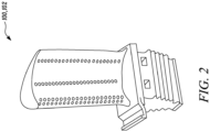
- Figure 2 shows a perspective view of a component 100 associated with the gas turbine engine 10 (see Figure 1 ).
- the component 100 is a blade 102 of the gas turbine engine 10.
- the blade 102 may be associated with any of the turbines 17, 19 (see Figure 1 ).
- the component 100 may include any other article, without any limitations.
- the component 100 is embodied as a single crystal component herein. Further, the component 100 may include a desired or predetermined crystallography.
- a system 400 (shown in Figure 4 ) is provided for forming components and articles which is independent of nucleation propensity for stray grains at and above a crystal seed melt-back level in comparison with prior methods of formation of single crystal component.
- Figure 3 is a photographic micro-structural cross-section illustrating dendritic growth of stray grains. Specifically, Figure 3 illustrates nucleation of stray grains that occur when the local solutal under-cooling exceeds the critical nucleation under-cooling and, therefore, is associated with the transient at a mould wall 300. Nucleation occurs at or behind primary dendrite tips 302 driven by under-cooling considerations.
- the dendrites begin to grow into a constitutionally under-cooled liquid ahead of the tips 302.
- the growth characteristics of the single crystal dendrites are dependent on the inclination of the off-axial dendrites in relation to the mould wall 300. This is due to the effects and implications of under-cooling associated with the solute pile-up in the vicinity of the tips 302 and the volume of liquid available, that is to say at the converging/diverging grooves at the mould wall 300.
- a region 306 where secondary grains may be formed is illustrated in Figure 3 .
- the system 400 includes a mould assembly 402 including a central sprue 404 extending along a central axis 406 and an initial mould unit 408. Further, the initial mould unit 408 is positioned on a carousel 410 of the system 400.
- the carousel 410 includes the central sprue 404.
- the initial mould unit 408 extends along a unit axis 412 parallel to the central axis 406. Further, the initial mould unit 408 is rotatable about the unit axis 412 with respect to the central sprue 404.
- the carousel 410 is configured to hold four initial mould units 408 (two of which are obstructed from view in Figure 4 ).
- the carousel 410 may hold any number of initial mould units 408 depending on a diameter of the carousel 410, without any limitations.
- the initial mould unit 408 includes a wax pattern 414 and a seed section 416 connected to the wax pattern 414. Accordingly, the wax pattern 414 and the seed section 416 may be together rotated about the unit axis 412 with respect to the central sprue 404.
- the wax pattern 414 is made of a wax material and the seed section 416 is made of a plastic material. Further, the wax pattern 414 and the seed section 416 are formed as a single integral component herein. Specifically, the wax pattern 414 may be formed along with the seed section 416 within a die, as the single integral component. In an example, the wax pattern 414 and the seed section 416 may be manufactured using an injection moulding process. A technique for manufacturing mould units wherein the wax pattern 414 and the seed section 416 are formed as a single integral component has been described in U.S. Patent Number 7,204,294 B2 assigned to Rolls Royce PLC and U.S. Patent Number 7,449,063 B2 assigned to Rolls Royce PLC, the contents of which are incorporated herein in their entirety.
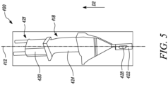
- the system 400 includes a refractory mould unit 418 extending along the unit axis 412.
- the refractory mould unit 418 includes a component mould 420 corresponding to the wax pattern 414 (see Figure 4 ) and a seed holder 422 corresponding to the seed section 416 (see Figure 4 ).
- the component mould 420 includes a mould wall 424 defining a mould cavity 426 (see Figure 6 ) that is disposed in fluid communication with the seed holder 422 and the central sprue 404 (see Figure 4 ).
- Each of the component mould 420 and the seed holder 422 is made of a refractory material.
- the refractory mould unit 418 is formed by encasing the initial mould unit 408 (see Figure 4 ) in the refractory material.
- the refractory material is a ceramic slurry.
- the ceramic slurry may include binding agents and mixtures of zircon (ZrSiO4), alumina (Al2O3), and silica (SiO2).
- ZrSiO4 zircon
- Al2O3 alumina
- silica SiO2
- the wax material and the plastic material are removed to form the refractory mould unit 418.
- the initial mould unit 408 is melted to remove the wax material and the plastic material.
- the mould wall 424 includes a first region 425 (shown in Figure 6 ) facing the central sprue 404 (see Figures 4 and 6 ).
- the first region 425 may be defined as a portion of the mould wall 424 that is in direct line of sight of the central sprue 404 and closest in proximity to the central sprue 404.
- the mould wall 424 also includes a second region 427 (shown in Figure 6 ). The second region 427 is distant from the central sprue 404.
- the refractory mould unit 418 includes an investment shell produced by coating the initial mould unit 408 with the refractory material.
- multiple coatings of the refractory material may be provided on the initial mould unit 408 until a desired thickness of the refractory mould unit 418 is obtained.
- the refractory mould unit 418 may be baked to build its strength.
- a first step in this direction may include subjecting the refractory mould unit 418 to a temperature just sufficient to melt out the wax material and the plastic material.
- a steam autoclave may be used to melt the wax material and the plastic material.
- the refractory mould unit 418 is subjected to higher temperatures. After preheating and degassing, the refractory mould unit 418 may be ready to receive a seed crystal 428 and a supply of molten castable material to form the component 100 (see Figure 2 ) as a single crystal structure.
- the seed crystal 428 is used to initiate crystal forming to manufacture the component 100.
- the seed crystal 428 includes the primary growth direction D1 (shown in Figure 6 ).
- the primary growth direction D1 is an axial direction.
- the seed crystal 428 also includes a secondary growth direction (not shown).
- the secondary growth direction is an azimuthal direction.
- the primary growth direction D1 and the secondary growth direction may be determined from two fundamental Euler angles.
- the seed crystal 428 is received within the seed holder 422. Further, the mould cavity 426 is filled with the molten castable material to form the component 100 as the single crystal structure.
- a mould heater 430 (shown in Figure 6 ) is adapted to heat the refractory mould unit 418.
- the mould heater 430 may include a furnace.
- the mould heater 430 is configured to face the second region 427 (shown in Figure 6 ) of the mould wall 424. More particularly, the second region 427 may be defined as a portion of the mould wall 424 that is in direct line of sight of the mould heater 430 and closest in proximity to the mould heater 430.
- a runner (not shown) of the system 400 may fluidly communicate the central sprue 404 with the mould cavity 426.
- the molten castable material may be directed towards the mould cavity 426 via the central sprue 404 and the runner.
- the molten castable material may be poured under vacuum conditions, at high temperatures.
- the refractory mould unit 418 may be removed mechanically, while any internal ceramic cores used to produce internal cooling passages may be removed by chemical means, for example, using a high-pressure autoclave.
- the system 400 may include other components (not shown herein), such as, a chill plate.
- the chill plate may be adapted to cool the seed crystal 428 and the bottom of the refractory mould unit 418 so as to assist in progressive solidification of the molten castable metal from the seed crystal 428 towards the opposite extremity of the refractory mould unit 418, i.e., in a direction D2.
- a temperature of the chill plate is preferably maintained such that the growth of dendrites begin at a lower end of the component mould 420, and the solidification front travels upward through the component mould 420 along the direction D2.
- an angular orientation of the wax pattern 414 in fluid communication with the seed portion 416 on the initial mould unit 408 about the central axis 406, and therefore a position of the refractory mould unit 418, is crucial in reducing a formation of secondary grains.
- the present disclosure is directed towards determination of an optimal angular orientation O1 of the wax pattern 414 in fluid communication with the seed portion 416 on the initial mould unit 408 about the central axis 406 relative to the central sprue 404 if the primary growth direction D1 of the seed crystal 428 is disposed at a predetermined orientation with respect to the initial mould unit 408.
- the predetermined orientation may be a preferred/fixed axial and azimuthal orientation.
- the optimal angular orientation O1 may correspond to an optimal position of the wax pattern 414 in fluid communication with the seed portion 416 on the initial mould unit 408 about the central axis 406 of the central sprue 404.
- the optimal angular orientation O1 is determined offline using a thermal model.
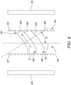
- the thermal model may be used to determine curvatures 602 of a plurality of liquidus isotherms 604 of the molten castable material as a function of time along the unit axis 412 for a given angular orientation of the initial mould unit 408 (see Figure 4 ) with respect to the central sprue 404 (see Figure 4 ). Further, an angle A1 defined between a normal 606 to the curvature 602 of the liquidus isotherm 604 and the unit axis 412 is determined.
- a disposition of the primary growth direction D1 of the seed crystal 428 (see Figure 5 ) for the given angular orientation is determined if the normal 606 to at least one liquidus isotherm 604 from the plurality of liquidus isotherms 604 is inclined to the unit axis 412 by the angle A1 greater than 15 degrees and if the at least one liquidus isotherm 604 slopes upwards towards an upper end 421 (see Figure 5 ) of the component mould 422 (see Figure 5 ).
- a number of instances where the normal 606 to at least one liquidus isotherm 604 from the plurality of liquidus isotherms 604 is inclined to the unit axis 412 by the angle A1 greater than 15 degrees is minimum and a number of instances where the at least one liquidus isotherm 604 slopes upwards towards the upper end 421 of the component mould 422 is minimum.
- the initial mould unit 408 is theoretically rotated to dispose the initial mould unit 408 at a second given angular orientation, and so on, until the optimal angular orientation O1 is obtained.
- the initial mould unit 408 is rotated about the unit axis 412, such that the initial mould unit 408 is disposed in the optimal angular orientation O1 relative to the central sprue 404.
- the refractory mould unit 418 is formed.
- the refractory mould unit 418 is also disposed in the optimal angular orientation O1 relative to the central sprue 404.
- the primary growth direction D1 of the seed crystal 428 is angled away from the mould wall 424, thereby forming a converging disposition with the mould wall 424 in the first region 425 of the mould wall 424 facing the central sprue 404 and a diverging disposition with the mould wall 424 in the second region 427 of the mould wall 424 facing the mould heater 430.
- the second region 427 is in direct line of sight of the mould heater 430 and experiences direct radiation
- the first region 425 experiences radiation shadowing which accounts for the shape of the liquidus isotherms 604.
- each mould unit 408 may be sequentially rotated so that the resulting liquidus isotherms 604 (as shown in Figure 6 ) are either flat, or are steep and curve upwards, so that the primary growth direction D1 (see Figure 6 ) of the seed crystal 428 forms the converging disposition with the mould wall 424 in the first region 425 of the mould wall 424. Moreover, when the seed crystal 428 is received within the seed holder 422, the primary growth direction D1 of the seed crystal 428 forms the converging disposition with the mould wall 424 in the first region 425 of the mould wall 424.
- the dendrites form the converging disposition with the mould wall 424 in the first region 425 of the mould wall 424 to prevent formation and stabilization of secondary grains.
- Figure 7 illustrates another embodiment of the present disclosure.
- a primary growth direction D1-1 of the seed crystal 428 (see Figure 5 ) is independent of an orientation of the initial mould unit 408 (see Figure 4 ).
- the embodiment illustrated in Figure 7 is applicable to components where the primary growth direction D1-1 of the seed crystal 428 is not fixed.
- the seed crystal 428 may be disposed within the seed holder 422 (see Figure 5 ), such that the primary growth direction D1-1 of the seed crystal 428 is from 0 degree to 4 degrees with respect to the unit axis 412.
- the seed crystal 428 is disposed in the seed holder 422 such that an angle A2 is defined between the primary growth direction D1-1 and the unit axis 412.
- a value of the angle A2 may be between 0 degree to 4 degrees.
- the seed crystal 428 may have any other primary growth direction, such as, a primary growth direction D1-2.
- the primary growth direction D1-2 may be inclined by 0 degree to 4 degrees with respect to the unit axis 412. Therefore, the seed crystal 428 may be disposed within the seed holder 422, such that the primary growth direction D1-1 of the seed crystal 428 lies within an imaginary cone defined around the unit axis 412 with a cone half angle equal to the angle A2.
- FIG 8 illustrates a flowchart for a method 800 of manufacturing the component 100.
- the mould assembly 402 is formed.
- the mould assembly 402 includes the central sprue 404 extending along the central axis 406 and the initial mould unit 408 including the wax pattern 414 and the seed section 416 connected to the wax pattern 414.
- the wax pattern 414 is made of the wax material and the seed section 416 is made of the plastic material.
- the initial mould unit 408 extends along the unit axis 412 parallel to the central axis 406.
- the initial mould unit 408 is rotatable about the unit axis 412 with respect to the central sprue 404.
- the wax pattern 414 and the seed section 416 are formed as the single integral component.
- the component 100 is the blade 102 of the gas turbine engine 10.
- the blade 102 manufactured by the method 800 of the first aspect may have reduced surface defects and may have improved conformance to the specifications of the blade 102.
- the blade 102 may achieve desired operational performance due to conformance to the specifications.
- the seed crystal 428 including the primary growth direction D1 is provided.
- the optimal angular orientation O1 of the initial mould unit 408 about the central axis 406 relative to the central sprue 404 is determined if the primary growth direction D1 of the seed crystal 428 is disposed at the predetermined orientation with respect to the initial mould unit 408.
- the curvatures 602 of the plurality of liquidus isotherms 604 of the molten castable material as a function of time are determined for the given angular orientation of the initial mould unit 408 with respect to the central sprue 404.
- the disposition of the primary growth direction D1 of the seed crystal 428 for the given angular orientation is determined if the normal 606 to at least one liquidus isotherm 604 from the plurality of liquidus isotherms 604 is inclined to the unit axis 412 by the angle A1 greater than 15 degrees and if the at least one liquidus isotherm 604 slopes upwards towards the upper end 421 of the component mould 422. Furthermore, the given angular orientation is varied and the curvatures 602 of the plurality of liquidus isotherms 604 of the molten castable material as well as the disposition of the primary growth direction D1 of the seed crystal 428 for the given angular orientation is determined till the optimal angular orientation O1 is obtained.
- the initial mould unit 408 is positioned on the carousel 410 including the central sprue 404 prior to rotating the initial mould unit 408 about the unit axis 412.
- the number of instances where the normal 606 to at least one liquidus isotherm 604 from the plurality of liquidus isotherms 604 is inclined to the unit axis 412 by the angle A1 greater than 15 degrees is minimum and the number of instances where the at least one liquidus isotherm 604 slopes upwards towards the upper end 421 of the component mould 422 is minimum.
- the optimal angular orientation O1 of the initial mould unit 408 can be deduced which may reduce the probability of formation of secondary grains.
- the initial mould unit 408 is rotated about the unit axis 412, such that the initial mould unit 408 is disposed in the optimal angular orientation O1 relative to the central sprue 404. Due to the positioning of the initial mould unit 408 in the optimal angular orientation O1, the primary growth direction D1 of the seed crystal 428 is angled away from the mould wall 424, thereby forming the converging disposition with the mould wall 424 in the first region 425 which may reduce a probability of formation of secondary grains.
- the method 800 of obtaining the optimal angular orientation O1 of the initial mould unit 408 for any blade geometry may minimise the formation and subsequent stabilisation of the secondary grains, thereby reducing a possibility of non-conformance to the specifications of the component 100.
- the initial mould unit 408 is encased in the refractory material after disposing the initial mould unit 408 in the optimal angular orientation O1 relative to the central sprue 404.
- the refractory material is the ceramic slurry.
- the refractory mould unit 418 includes the component mould 420 corresponding to the wax pattern 414 and the seed holder 422 corresponding to the seed section 416.
- the component mould 420 includes the mould wall 424 defining the mould cavity 426 that is disposed in fluid communication with the seed holder 422 and the central sprue 404.
- Each of the component mould 420 and the seed holder 422 is made of the refractory material.
- the refractory mould unit 418 is disposed in the optimal angular orientation O1 relative to the central sprue 404.
- the primary growth direction D1 of the seed crystal 428 is angled away from the mould wall 424, thereby forming the converging disposition with the mould wall 424 in the first region 425 of the mould wall 424 facing the central sprue 404 and the diverging disposition with the mould wall 424 in the second region 427 of the mould wall 424 facing the mould heater 430.
- the seed crystal 428 is received within the seed holder 422, such that the primary growth direction D1 of the seed crystal 428 forms the converging disposition with the mould wall 424 in the first region 425 of the mould wall 424 and the diverging disposition with the mould wall 424 in the second region 427 of the mould wall 424.
- the mould cavity 426 is filled with the molten castable material via the central sprue 404 to form the component 100 as the single crystal structure.
- the method 800 includes a step of determining if the primary growth direction D1-1 of the seed crystal 428 is independent of the orientation of the initial mould unit 408. Further, the method 800 includes a step of removing the wax material and the plastic material to form the refractory mould unit 418 extending along the unit axis 412 without rotating the initial mould unit 408 to the optimal angular orientation O1 relative to the central sprue 404. The method 800 further includes a step of receiving the seed crystal 428 within the seed holder 422, such that the primary growth direction D1-1 of the seed crystal 428 is from 0 degree to 4 degrees with respect to the unit axis 412.
- the primary growth direction D1-1 of the seed crystal 428 may be between 0 degree and 4 degrees with respect to the unit axis 412, which may reduce the formation of secondary grains and reduce non-conformance to the specifications of the component 100.
Landscapes
- Engineering & Computer Science (AREA)
- Mechanical Engineering (AREA)
- Crystals, And After-Treatments Of Crystals (AREA)
Abstract
Description
- The present disclosure relates to a gas turbine engine, and a method of manufacturing a component that may be associated with the gas turbine engine.
- Certain articles and components, such as aerofoil blades for gas turbine engines, are preferably formed with known crystallography in order to achieve desired operational performance. For example, a desired crystallography may allow the components to be more resistant to high temperature creep. A number of methods have been identified for forming single crystal components. Such methods generally utilise a seed crystal to initiate crystal formation in the component within a mould. What is generally required is a mechanism to ensure that the desired crystallography is achieved. However, conventional methods have disadvantages in attempting to successfully circumvent hazards with respect to stray grain nucleation in growth.
- The occurrence of stray grains in single crystal castings is detrimental and needs to be avoided, which requires a very tight specification to being adhered to. Such stray grains are typically located proximate to a surface of the cast component. Further, the stray grains in such regions invariably bear an orientation relationship with the primary single crystal grain and are not randomly nucleated.
- According to a first aspect, there is provided a method of manufacturing a component. The method includes forming a mould assembly including a central sprue extending along a central axis and an initial mould unit including a wax pattern and a seed section connected to the wax pattern. The wax pattern is made of a wax material and the seed section is made of a plastic material. The initial mould unit extends along a unit axis parallel to the central axis. The initial mould unit is rotatable about the unit axis with respect to the central sprue. The method further includes providing a seed crystal including a primary growth direction. The method further includes determining an optimal angular orientation of the initial mould unit about the central axis relative to the central sprue if the primary growth direction of the seed crystal is disposed at a predetermined orientation with respect to the initial mould unit. The method further includes rotating the initial mould unit about the unit axis, such that the initial mould unit is disposed in the optimal angular orientation relative to the central sprue. The method further includes encasing the initial mould unit in a refractory material after disposing the initial mould unit in the optimal angular orientation relative to the central sprue. The method further includes removing the wax material and the plastic material to form a refractory mould unit extending along the unit axis. The refractory mould unit includes a component mould corresponding to the wax pattern and a seed holder corresponding to the seed section. The component mould includes a mould wall defining a mould cavity that is disposed in fluid communication with the seed holder and the central sprue. Each of the component mould and the seed holder is made of the refractory material. The refractory mould unit is disposed in the optimal angular orientation relative to the central sprue. In the optimal angular orientation of the refractory mould unit, the primary growth direction of the seed crystal is angled away from the mould wall, thereby forming a converging disposition with the mould wall in a first region of the mould wall facing the central sprue and a diverging disposition with the mould wall in a second region of the mould wall facing a mould heater. The method further includes receiving the seed crystal within the seed holder, such that the primary growth direction of the seed crystal forms the converging disposition with the mould wall in the first region of the mould wall and the diverging disposition with the mould wall in the second region of the mould wall. The method further includes filling, via the central sprue, the mould cavity with molten castable material to form the component as a single crystal structure.
- Due to the positioning of the initial mould unit in the optimal angular orientation, the primary growth direction of the seed crystal is angled away from the mould wall, thereby forming the converging disposition with the mould wall in the first region facing the central sprue, which may reduce a probability of formation of secondary grains. In some examples, due to the converging disposition with the mould wall in the first region, any deformation of the dendrites close to the liquidus isotherms leading to a secondary grain is stabilized because such bent/twisted dendrites constituting a secondary grain are easily overgrown by primary dendrites of the main grain, which reduces the probability of secondary grain formation and growth. At the diverging mould wall, although deformation of secondary dendrites can also occur, the shape of the isotherms (downward sloping) also stabilises the growth of the primary dendrites of the main grain over those of the secondary grains. Thus, the method of obtaining the optimal angular orientation of the initial mould unit for any blade geometry may minimise the formation and subsequent stabilisation of secondary grains, thereby reducing a possibility of non-conformance to the specifications of the component.
- In some embodiments, determining the optimal angular orientation of the initial mould unit includes a) determining, using a thermal model, curvatures of a plurality of liquidus isotherms of the molten castable material as a function of time along the unit axis for a given angular orientation of the initial mould unit with respect to the central sprue. Further, determining the optimal angular orientation of the initial mould unit further includes b) determining, using the thermal model, a disposition of the primary growth direction of the seed crystal for the given angular orientation if a normal to at least one liquidus isotherm from the plurality of liquidus isotherms is inclined to the unit axis by an angle greater than 15 degrees and if the at least one liquidus isotherm slopes upwards towards an upper end of the component mould. Furthermore, determining the optimal angular orientation of the initial mould unit further includes c) repeating steps a) and b) by varying the given angular orientation till the optimal angular orientation is obtained. In the optimum orientation, a number of instances where the normal to at least one liquidus isotherm from the plurality of liquidus isotherms is inclined to the unit axis by the angle greater than 15 degrees is minimum and a number of instances where at least one liquidus isotherm slopes upwards towards the upper end of the component mould is minimum. Thus, from amongst a multitude of possible angular orientations obtained iteratively through theoretical rotation of the initial mould unit on the carousel and calculations of the curvatures of the liquidus isotherms using the thermal model, the optimal angular orientation of the initial mould unit can be deduced which may reduce the probability of formation of secondary grains.
- In some embodiments, the method further includes determining that the primary growth direction of the seed crystal is independent of an orientation of the initial mould unit. The method further includes removing the wax material and the plastic material to form the refractory mould unit extending along the unit axis without rotating the initial mould unit to the optimal angular orientation relative to the central sprue. The method further includes receiving the seed crystal within the seed holder, such that the primary growth direction of the seed holder is from 0 degree to 4 degrees with respect to the unit axis. Thus, when no preferred primary (axial) and secondary (azimuthal) orientation is required for the component, the primary growth direction of the seed holder may be between 0 degree and 4 degrees with respect to the unit axis which may reduce the formation of secondary grains and reduce non-conformance.
- In some embodiments, the method further includes positioning the initial mould unit on a carousel including the central sprue prior to rotating the initial mould unit about the unit axis. Specifically, the initial mould unit is positioned on the carousel such that the initial mould unit may be rotated to the optimal angular orientation.
- In some embodiments, the refractory material is a ceramic slurry. The ceramic slurry is configured to coat the wax pattern and the seed section.
- In some embodiments, the wax pattern and the seed section are formed as a single integral component. Thus, the wax pattern and the seed section may be rotated together to dispose the initial mould unit in the desired optimal angular orientation.
- In some embodiments, the component is a blade of a gas turbine engine. The blade manufactured by the method of the first aspect may have reduced surface defects and may have improved conformance to the specifications of the blade. Thus, the blade may achieve desired operational performance due to conformance to the specifications.
- According to a second aspect, there is provided a component for a gas turbine engine manufactured according to the method of the first aspect. The component manufactured by the method of the first aspect may have reduced surface defects and may have improved conformance to the specifications of the component. Thus, the component may achieve desired operational performance due to conformance to the specifications
- As noted elsewhere herein, the present disclosure may relate to a gas turbine engine. Such a gas turbine engine may comprise an engine core comprising a turbine, a combustor, a compressor, and a core shaft connecting the turbine to the compressor. Such a gas turbine engine may comprise a fan (having fan blades) located upstream of the engine core.
- Arrangements of the present disclosure may be particularly, although not exclusively, beneficial for fans that are driven via a gearbox. Accordingly, the gas turbine engine may comprise a gearbox that receives an input from the core shaft and outputs drive to the fan so as to drive the fan at a lower rotational speed than the core shaft. The input to the gearbox may be directly from the core shaft, or indirectly from the core shaft, for example via a spur shaft and/or gear. The core shaft may rigidly connect the turbine and the compressor, such that the turbine and compressor rotate at the same speed (with the fan rotating at a lower speed). The gearbox may be a reduction gearbox (in that the output to the fan is a lower rotational rate than the input from the core shaft). Any type of gearbox may be used.
- The gas turbine engine as described and/or claimed herein may have any suitable general architecture. For example, the gas turbine engine may have any desired number of shafts that connect turbines and compressors, for example one, two or three shafts. Purely by way of example, the turbine connected to the core shaft may be a first turbine, the compressor connected to the core shaft may be a first compressor, and the core shaft may be a first core shaft. The engine core may further comprise a second turbine, a second compressor, and a second core shaft connecting the second turbine to the second compressor. The second turbine, second compressor, and second core shaft may be arranged to rotate at a higher rotational speed than the first core shaft.
- In such an arrangement, the second compressor may be positioned axially downstream of the first compressor. The second compressor may be arranged to receive (for example directly receive, for example via a generally annular duct) flow from the first compressor.
- In any gas turbine engine as described and/or claimed herein, a combustor may be provided axially downstream of the fan and compressor(s). For example, the combustor may be directly downstream of (for example at the exit of) the second compressor, where a second compressor is provided. By way of further example, the flow at the exit to the combustor may be provided to the inlet of the second turbine, where a second turbine is provided. The combustor may be provided upstream of the turbine(s).
- The or each compressor (for example the first compressor and second compressor as described above) may comprise any number of stages, for example multiple stages. Each stage may comprise a row of rotor blades and a row of stator vanes, which may be variable stator vanes (in that their angle of incidence may be variable). The row of rotor blades and the row of stator vanes may be axially offset from each other.
- The or each turbine (for example the first turbine and second turbine as described above) may comprise any number of stages, for example multiple stages. Each stage may comprise a row of rotor blades and a row of stator vanes. The row of rotor blades and the row of stator vanes may be axially offset from each other.
- Gas turbine engines in accordance with the present disclosure may have any desired bypass ratio, where the bypass ratio is defined as the ratio of the mass flow rate of the flow through the bypass duct to the mass flow rate of the flow through the core at cruise conditions. The bypass duct may be substantially annular. The bypass duct may be radially outside the engine core. The radially outer surface of the bypass duct may be defined by a nacelle and/or a fan case.
- Specific thrust of an engine may be defined as the net thrust of the engine divided by the total mass flow through the engine. At cruise conditions, the specific thrust of an engine described and/or claimed herein may be less than (or in the order of) any of the following: 110 Nkg-1s, 105 Nkg-1s, 100 Nkg-1s, 95 Nkg-1s, 90 Nkg-1s, 85 Nkg-1s or 80 Nkg-1s. The specific thrust may be in an inclusive range bounded by any two of the values in the previous sentence (i.e., the values may form upper or lower bounds), for example in the range of from 80 Nkg-1s to 100 Nkg-1s, or 85 Nkg-1s to 95 Nkg-1s. Such engines may be particularly efficient in comparison with conventional gas turbine engines.
- A fan blade and/or aerofoil portion of a fan blade described and/or claimed herein may be manufactured from any suitable material or combination of materials. For example, at least a part of the fan blade and/or aerofoil may be manufactured at least in part from a composite, for example a metal matrix composite and/or an organic matrix composite, such as carbon fibre.
- The fan of a gas turbine as described and/or claimed herein may have any desired number of fan blades, for example 14, 16, 18, 20, 22, 24 or 26 fan blades.
- The skilled person will appreciate that except where mutually exclusive, a feature or parameter described in relation to any one of the above aspects may be applied to any other aspect. Furthermore, except where mutually exclusive, any feature or parameter described herein may be applied to any aspect and/or combined with any other feature or parameter described herein.
- Embodiments will now be described by way of example only, with reference to the Figures, in which:
-
Figure 1 is a sectional side view of a gas turbine engine, according to an embodiment of the present disclosure; -
Figure 2 is a schematic perspective view of a component associated with a turbine of the gas turbine engine ofFigure 1 , according to an embodiment of the present disclosure; -
Figure 3 illustrates dendritic crystal growth from an exemplary wall of a refractory mould, according to an embodiment of the present disclosure; -
Figure 4 is a schematic perspective view of an initial mould unit for manufacturing the component ofFigure 2 , according to an embodiment of the present disclosure; -
Figure 5 is a schematic perspective view of a refractory mould unit for manufacturing the component ofFigure 2 , according to an embodiment of the present disclosure; -
Figure 6 is a schematic view illustrating a relationship between a liquidus isotherm and a primary growth direction of a seed crystal, according to an embodiment of the present disclosure; -
Figure 7 is a schematic view illustrating a relationship between a unit axis for the refractory mould unit and a primary growth direction of a seed crystal, according to another embodiment of the present disclosure; and -
Figure 8 is a flowchart for a method for manufacturing the component, according to an embodiment of the present disclosure. - Aspects and embodiments of the present disclosure will now be discussed with reference to the accompanying Figures. Further aspects and embodiments will be apparent to those skilled in the art.
-
Figure 1 illustrates agas turbine engine 10 having a principalrotational axis 9. Theengine 10 comprises anair intake 12 and apropulsive fan 23 that generates two airflows: a core airflow A and a bypass airflow B. Thegas turbine engine 10 comprises anengine core 11 that receives the core airflow A. Theengine core 11 comprises, in axial flow series, alow pressure compressor 14, ahigh pressure compressor 15, acombustion equipment 16, ahigh pressure turbine 17, alow pressure turbine 19, and acore exhaust nozzle 20. Anacelle 21 surrounds thegas turbine engine 10 and defines abypass duct 22 and abypass exhaust nozzle 18. The bypass airflow B flows through thebypass duct 22. Thefan 23 is attached to and driven by thelow pressure turbine 19 via ashaft 26 and anepicyclic gearbox 30. - In use, the core airflow A is accelerated and compressed by the
low pressure compressor 14 and directed into thehigh pressure compressor 15 where further compression takes place. The compressed air exhausted from thehigh pressure compressor 15 is directed into thecombustion equipment 16 where it is mixed with fuel and the mixture is combusted. The resultant hot combustion products then expand through, and thereby drive, the high pressure andlow pressure turbines core exhaust nozzle 20 to provide some propulsive thrust. Thehigh pressure turbine 17 drives thehigh pressure compressor 15 by a suitable interconnectingshaft 27. Thefan 23 generally provides the majority of the propulsive thrust. Theepicyclic gearbox 30 is a reduction gearbox. - Note that the terms "low pressure turbine" and "low pressure compressor" as used herein may be taken to mean the lowest pressure turbine stages and lowest pressure compressor stages (i.e., not including the fan 23) respectively and/or the turbine and compressor stages that are connected together by the interconnecting
shaft 26 with the lowest rotational speed in the engine 100 (i.e., not including the gearbox output shaft that drives the fan 23). In some literature, the "low pressure turbine" and "low pressure compressor" referred to herein may alternatively be known as the "intermediate pressure turbine" and "intermediate pressure compressor". Where such alternative nomenclature is used, thefan 23 may be referred to as a first, or lowest pressure, compression stage. - Other gas turbine engines to which the present disclosure may be applied may have alternative configurations. For example, such engines may have an alternative number of compressors and/or turbines and/or an alternative number of interconnecting shafts. By way of further example, the gas turbine engine shown in
Figure 1 has asplit flow nozzle bypass duct 22 has itsown nozzle 18 that is separate to and radially outside thecore exhaust nozzle 20. However, this is not limiting, and any aspect of the present disclosure may also apply to engines in which the flow through thebypass duct 22 and the flow through the core 11 are mixed, or combined, before (or upstream of) a single nozzle, which may be referred to as a mixed flow nozzle. One or both nozzles (whether mixed or split flow) may have a fixed or variable area. Whilst the described example relates to a turbofan engine, the disclosure may apply, for example, to any type of gas turbine engine, such as an open rotor (in which the fan stage is not surrounded by a nacelle) or turboprop engine, for example. In some arrangements, thegas turbine engine 10 may not comprise agearbox 30. - The geometry of the
gas turbine engine 10, and components thereof, is defined by a conventional axis system, comprising an axial direction (which is aligned with the rotational axis 9), a radial direction (in the bottom-to-top direction inFigure 1 ), and a circumferential direction (perpendicular to the page in theFigure 1 view). The axial, radial, and circumferential directions are mutually perpendicular. - In addition, the present disclosure is equally applicable to aero gas turbine engines, marine gas turbine engines, and land-based gas turbine engines.
-
Figure 2 shows a perspective view of a component 100 associated with the gas turbine engine 10 (seeFigure 1 ). In the illustrated embodiment ofFigure 2 , the component 100 is a blade 102 of thegas turbine engine 10. The blade 102 may be associated with any of theturbines 17, 19 (seeFigure 1 ). In other examples, the component 100 may include any other article, without any limitations. The component 100 is embodied as a single crystal component herein. Further, the component 100 may include a desired or predetermined crystallography. - An objective with regard to producing components with a predetermined or desired crystallography is to ensure that initiation and propagation of stray grain growth is inhibited or limited. In accordance with certain aspects of the present disclosure, a system 400 (shown in
Figure 4 ) is provided for forming components and articles which is independent of nucleation propensity for stray grains at and above a crystal seed melt-back level in comparison with prior methods of formation of single crystal component. -
Figure 3 is a photographic micro-structural cross-section illustrating dendritic growth of stray grains. Specifically,Figure 3 illustrates nucleation of stray grains that occur when the local solutal under-cooling exceeds the critical nucleation under-cooling and, therefore, is associated with the transient at amould wall 300. Nucleation occurs at or behindprimary dendrite tips 302 driven by under-cooling considerations. - When considering the dendritic growth characteristics subsequent to nucleation, it will be noted that the dendrites begin to grow into a constitutionally under-cooled liquid ahead of the
tips 302. The growth characteristics of the single crystal dendrites are dependent on the inclination of the off-axial dendrites in relation to themould wall 300. This is due to the effects and implications of under-cooling associated with the solute pile-up in the vicinity of thetips 302 and the volume of liquid available, that is to say at the converging/diverging grooves at themould wall 300. - As shown in
Figure 3 , only in the case of a diverging disposition of a primary growth direction D1 (shown inFigure 6 ) of a seed crystal 428 (shown inFigure 5 ) with themould wall 300, there exists an extensive network ofsecondary arms 304 that can potentially act as sites where deformation accumulates and leads to bending of thesesecondary arms 304 at their roots. However, the most important aspect relates to stability of tertiary arms emanating from a bentsecondary arm 304, that can grow competitively. Only when the tertiary arms escape the solute field of the neighbouring dendrite network, can a tertiary arm grow stably and successively branch and also extend across the cross-section giving rise to a secondary grain of finite size that may cause defects and non-conformance in the final component, which is not desirable. Aregion 306 where secondary grains may be formed is illustrated inFigure 3 . - The
system 400 for manufacturing the component 100 that addresses the above mentioned shortcomings will now be explained in relation toFigures 4 to 7 . - Referring to
Figure 4 , thesystem 400 includes amould assembly 402 including acentral sprue 404 extending along acentral axis 406 and aninitial mould unit 408. Further, theinitial mould unit 408 is positioned on acarousel 410 of thesystem 400. Thecarousel 410 includes thecentral sprue 404. Theinitial mould unit 408 extends along aunit axis 412 parallel to thecentral axis 406. Further, theinitial mould unit 408 is rotatable about theunit axis 412 with respect to thecentral sprue 404. In the illustrated embodiment ofFigure 4 , thecarousel 410 is configured to hold four initial mould units 408 (two of which are obstructed from view inFigure 4 ). Alternatively, thecarousel 410 may hold any number ofinitial mould units 408 depending on a diameter of thecarousel 410, without any limitations. Theinitial mould unit 408 includes awax pattern 414 and aseed section 416 connected to thewax pattern 414. Accordingly, thewax pattern 414 and theseed section 416 may be together rotated about theunit axis 412 with respect to thecentral sprue 404. - Further, the
wax pattern 414 is made of a wax material and theseed section 416 is made of a plastic material. Further, thewax pattern 414 and theseed section 416 are formed as a single integral component herein. Specifically, thewax pattern 414 may be formed along with theseed section 416 within a die, as the single integral component. In an example, thewax pattern 414 and theseed section 416 may be manufactured using an injection moulding process. A technique for manufacturing mould units wherein thewax pattern 414 and theseed section 416 are formed as a single integral component has been described inU.S. Patent Number 7,204,294 B2 assigned to Rolls Royce PLC andU.S. Patent Number 7,449,063 B2 assigned to Rolls Royce PLC, the contents of which are incorporated herein in their entirety. - Referring now to
Figure 5 , thesystem 400 includes arefractory mould unit 418 extending along theunit axis 412. Therefractory mould unit 418 includes acomponent mould 420 corresponding to the wax pattern 414 (seeFigure 4 ) and a seed holder 422 corresponding to the seed section 416 (seeFigure 4 ). Thecomponent mould 420 includes amould wall 424 defining a mould cavity 426 (seeFigure 6 ) that is disposed in fluid communication with the seed holder 422 and the central sprue 404 (seeFigure 4 ). Each of thecomponent mould 420 and the seed holder 422 is made of a refractory material. Specifically, therefractory mould unit 418 is formed by encasing the initial mould unit 408 (seeFigure 4 ) in the refractory material. The refractory material is a ceramic slurry. In an example, the ceramic slurry may include binding agents and mixtures of zircon (ZrSiO4), alumina (Al2O3), and silica (SiO2). Further, the wax material and the plastic material are removed to form therefractory mould unit 418. In an example, theinitial mould unit 408 is melted to remove the wax material and the plastic material. Further, themould wall 424 includes a first region 425 (shown inFigure 6 ) facing the central sprue 404 (seeFigures 4 and6 ). More particularly, thefirst region 425 may be defined as a portion of themould wall 424 that is in direct line of sight of thecentral sprue 404 and closest in proximity to thecentral sprue 404. Themould wall 424 also includes a second region 427 (shown inFigure 6 ). Thesecond region 427 is distant from thecentral sprue 404. - Thus, the
refractory mould unit 418 includes an investment shell produced by coating theinitial mould unit 408 with the refractory material. In some examples, multiple coatings of the refractory material may be provided on theinitial mould unit 408 until a desired thickness of therefractory mould unit 418 is obtained. Further, therefractory mould unit 418 may be baked to build its strength. A first step in this direction may include subjecting therefractory mould unit 418 to a temperature just sufficient to melt out the wax material and the plastic material. In some examples, a steam autoclave may be used to melt the wax material and the plastic material. - Further, the
refractory mould unit 418 is subjected to higher temperatures. After preheating and degassing, therefractory mould unit 418 may be ready to receive a seed crystal 428 and a supply of molten castable material to form the component 100 (seeFigure 2 ) as a single crystal structure. The seed crystal 428 is used to initiate crystal forming to manufacture the component 100. The seed crystal 428 includes the primary growth direction D1 (shown inFigure 6 ). The primary growth direction D1 is an axial direction. The seed crystal 428 also includes a secondary growth direction (not shown). The secondary growth direction is an azimuthal direction. The primary growth direction D1 and the secondary growth direction may be determined from two fundamental Euler angles. - The seed crystal 428 is received within the seed holder 422. Further, the
mould cavity 426 is filled with the molten castable material to form the component 100 as the single crystal structure. Further, a mould heater 430 (shown inFigure 6 ) is adapted to heat therefractory mould unit 418. Themould heater 430 may include a furnace. Themould heater 430 is configured to face the second region 427 (shown inFigure 6 ) of themould wall 424. More particularly, thesecond region 427 may be defined as a portion of themould wall 424 that is in direct line of sight of themould heater 430 and closest in proximity to themould heater 430. A runner (not shown) of thesystem 400 may fluidly communicate thecentral sprue 404 with themould cavity 426. Thus, the molten castable material may be directed towards themould cavity 426 via thecentral sprue 404 and the runner. In an example, the molten castable material may be poured under vacuum conditions, at high temperatures. After solidification is complete, therefractory mould unit 418 may be removed mechanically, while any internal ceramic cores used to produce internal cooling passages may be removed by chemical means, for example, using a high-pressure autoclave. - It should be noted that the
system 400 may include other components (not shown herein), such as, a chill plate. The chill plate may be adapted to cool the seed crystal 428 and the bottom of therefractory mould unit 418 so as to assist in progressive solidification of the molten castable metal from the seed crystal 428 towards the opposite extremity of therefractory mould unit 418, i.e., in a direction D2. A temperature of the chill plate is preferably maintained such that the growth of dendrites begin at a lower end of thecomponent mould 420, and the solidification front travels upward through thecomponent mould 420 along the direction D2. - Referring to
Figures 4 and5 , it was observed that an angular orientation of thewax pattern 414 in fluid communication with theseed portion 416 on theinitial mould unit 408 about thecentral axis 406, and therefore a position of therefractory mould unit 418, is crucial in reducing a formation of secondary grains. Thus, the present disclosure is directed towards determination of an optimal angular orientation O1 of thewax pattern 414 in fluid communication with theseed portion 416 on theinitial mould unit 408 about thecentral axis 406 relative to thecentral sprue 404 if the primary growth direction D1 of the seed crystal 428 is disposed at a predetermined orientation with respect to theinitial mould unit 408. In an example, the predetermined orientation may be a preferred/fixed axial and azimuthal orientation. Further, the optimal angular orientation O1 may correspond to an optimal position of thewax pattern 414 in fluid communication with theseed portion 416 on theinitial mould unit 408 about thecentral axis 406 of thecentral sprue 404. The optimal angular orientation O1 is determined offline using a thermal model. - Referring now to
Figure 6 , in order to determine the optimal angular orientation O1 (seeFigure 4 ) of the initial mould unit 408 (seeFigure 4 ), the thermal model may be used to determinecurvatures 602 of a plurality ofliquidus isotherms 604 of the molten castable material as a function of time along theunit axis 412 for a given angular orientation of the initial mould unit 408 (seeFigure 4 ) with respect to the central sprue 404 (seeFigure 4 ). Further, an angle A1 defined between a normal 606 to thecurvature 602 of theliquidus isotherm 604 and theunit axis 412 is determined. - Furthermore, using the thermal model, a disposition of the primary growth direction D1 of the seed crystal 428 (see
Figure 5 ) for the given angular orientation is determined if the normal 606 to at least oneliquidus isotherm 604 from the plurality ofliquidus isotherms 604 is inclined to theunit axis 412 by the angle A1 greater than 15 degrees and if the at least oneliquidus isotherm 604 slopes upwards towards an upper end 421 (seeFigure 5 ) of the component mould 422 (seeFigure 5 ). Thus, based on the thermal model, if the normal 606 to theliquidus isotherms 604 deviates from theunit axis 412 by greater than 15 degrees frequently, it implies thatcurvatures 602 of the one ormore liquidus isotherms 604 are steep, then it is advisable that the dendrites converge on to themould wall 424, rather than diverge. This is from the perspective of mitigating the formation and subsequent stabilisation of the secondary grains. In the optimum orientation, a number of instances where the normal 606 to at least oneliquidus isotherm 604 from the plurality ofliquidus isotherms 604 is inclined to theunit axis 412 by the angle A1 greater than 15 degrees is minimum and a number of instances where the at least oneliquidus isotherm 604 slopes upwards towards theupper end 421 of the component mould 422 is minimum. Thus, if the primary growth direction D1 of the seed crystal 428 is not angled away from themould wall 424 or if the primary growth direction D1 of the seed crystal 428 forms a diverging disposition with themould wall 424, theinitial mould unit 408 is theoretically rotated to dispose theinitial mould unit 408 at a second given angular orientation, and so on, until the optimal angular orientation O1 is obtained. - Referring again to
Figures 4 and5 , theinitial mould unit 408 is rotated about theunit axis 412, such that theinitial mould unit 408 is disposed in the optimal angular orientation O1 relative to thecentral sprue 404. Once theinitial mould unit 408 is disposed at the optimal angular orientation O1, therefractory mould unit 418 is formed. Thus, therefractory mould unit 418 is also disposed in the optimal angular orientation O1 relative to thecentral sprue 404. Further, in the optimal angular orientation O1 of therefractory mould unit 418, the primary growth direction D1 of the seed crystal 428 is angled away from themould wall 424, thereby forming a converging disposition with themould wall 424 in thefirst region 425 of themould wall 424 facing thecentral sprue 404 and a diverging disposition with themould wall 424 in thesecond region 427 of themould wall 424 facing themould heater 430. It should be noted that thesecond region 427 is in direct line of sight of themould heater 430 and experiences direct radiation, whereas thefirst region 425 experiences radiation shadowing which accounts for the shape of theliquidus isotherms 604. - Further, each
mould unit 408 may be sequentially rotated so that the resulting liquidus isotherms 604 (as shown inFigure 6 ) are either flat, or are steep and curve upwards, so that the primary growth direction D1 (seeFigure 6 ) of the seed crystal 428 forms the converging disposition with themould wall 424 in thefirst region 425 of themould wall 424. Moreover, when the seed crystal 428 is received within the seed holder 422, the primary growth direction D1 of the seed crystal 428 forms the converging disposition with themould wall 424 in thefirst region 425 of themould wall 424. Thus, according to the present disclosure, it is imperative to ensure that when theliquidus isotherms 604 have steep upwards curvature, the dendrites form the converging disposition with themould wall 424 in thefirst region 425 of themould wall 424 to prevent formation and stabilization of secondary grains. -
Figure 7 illustrates another embodiment of the present disclosure. In this embodiment, a primary growth direction D1-1 of the seed crystal 428 (seeFigure 5 ) is independent of an orientation of the initial mould unit 408 (seeFigure 4 ). In other words, the embodiment illustrated inFigure 7 is applicable to components where the primary growth direction D1-1 of the seed crystal 428 is not fixed. In such embodiments, the seed crystal 428 may be disposed within the seed holder 422 (seeFigure 5 ), such that the primary growth direction D1-1 of the seed crystal 428 is from 0 degree to 4 degrees with respect to theunit axis 412. In other words, the seed crystal 428 is disposed in the seed holder 422 such that an angle A2 is defined between the primary growth direction D1-1 and theunit axis 412. Further, a value of the angle A2 may be between 0 degree to 4 degrees. It should be noted that, as the primary growth direction D1-1 is not fixed, the seed crystal 428 may have any other primary growth direction, such as, a primary growth direction D1-2. However, the primary growth direction D1-2 may be inclined by 0 degree to 4 degrees with respect to theunit axis 412. Therefore, the seed crystal 428 may be disposed within the seed holder 422, such that the primary growth direction D1-1 of the seed crystal 428 lies within an imaginary cone defined around theunit axis 412 with a cone half angle equal to the angle A2. -
Figure 8 illustrates a flowchart for amethod 800 of manufacturing the component 100. Referring toFigures 1 to 6 , andFigure 8 , atstep 802, themould assembly 402 is formed. Themould assembly 402 includes thecentral sprue 404 extending along thecentral axis 406 and theinitial mould unit 408 including thewax pattern 414 and theseed section 416 connected to thewax pattern 414. Thewax pattern 414 is made of the wax material and theseed section 416 is made of the plastic material. Theinitial mould unit 408 extends along theunit axis 412 parallel to thecentral axis 406. Theinitial mould unit 408 is rotatable about theunit axis 412 with respect to thecentral sprue 404. Thewax pattern 414 and theseed section 416 are formed as the single integral component. Further, the component 100 is the blade 102 of thegas turbine engine 10. The blade 102 manufactured by themethod 800 of the first aspect may have reduced surface defects and may have improved conformance to the specifications of the blade 102. Thus, the blade 102 may achieve desired operational performance due to conformance to the specifications. - At
step 804, the seed crystal 428 including the primary growth direction D1 is provided. Atstep 806, the optimal angular orientation O1 of theinitial mould unit 408 about thecentral axis 406 relative to thecentral sprue 404 is determined if the primary growth direction D1 of the seed crystal 428 is disposed at the predetermined orientation with respect to theinitial mould unit 408. For determining the optimal angular orientation O1 of theinitial mould unit 408, using the thermal model, thecurvatures 602 of the plurality ofliquidus isotherms 604 of the molten castable material as a function of time are determined for the given angular orientation of theinitial mould unit 408 with respect to thecentral sprue 404. Further, using the thermal model, the disposition of the primary growth direction D1 of the seed crystal 428 for the given angular orientation is determined if the normal 606 to at least oneliquidus isotherm 604 from the plurality ofliquidus isotherms 604 is inclined to theunit axis 412 by the angle A1 greater than 15 degrees and if the at least oneliquidus isotherm 604 slopes upwards towards theupper end 421 of the component mould 422. Furthermore, the given angular orientation is varied and thecurvatures 602 of the plurality ofliquidus isotherms 604 of the molten castable material as well as the disposition of the primary growth direction D1 of the seed crystal 428 for the given angular orientation is determined till the optimal angular orientation O1 is obtained. Further, theinitial mould unit 408 is positioned on thecarousel 410 including thecentral sprue 404 prior to rotating theinitial mould unit 408 about theunit axis 412. In the optimum orientation, the number of instances where the normal 606 to at least oneliquidus isotherm 604 from the plurality ofliquidus isotherms 604 is inclined to theunit axis 412 by the angle A1 greater than 15 degrees is minimum and the number of instances where the at least oneliquidus isotherm 604 slopes upwards towards theupper end 421 of the component mould 422 is minimum. Thus, from amongst a multitude of possible angular orientations obtained iteratively through theoretical rotation of theinitial mould unit 408 on thecarousel 410 and calculations of thecurvatures 602 of theliquidus isotherms 604 using the thermal model, the optimal angular orientation O1 of theinitial mould unit 408 can be deduced which may reduce the probability of formation of secondary grains. - At
step 808, theinitial mould unit 408 is rotated about theunit axis 412, such that theinitial mould unit 408 is disposed in the optimal angular orientation O1 relative to thecentral sprue 404. Due to the positioning of theinitial mould unit 408 in the optimal angular orientation O1, the primary growth direction D1 of the seed crystal 428 is angled away from themould wall 424, thereby forming the converging disposition with themould wall 424 in thefirst region 425 which may reduce a probability of formation of secondary grains. Thus, themethod 800 of obtaining the optimal angular orientation O1 of theinitial mould unit 408 for any blade geometry may minimise the formation and subsequent stabilisation of the secondary grains, thereby reducing a possibility of non-conformance to the specifications of the component 100. - At
step 810, theinitial mould unit 408 is encased in the refractory material after disposing theinitial mould unit 408 in the optimal angular orientation O1 relative to thecentral sprue 404. The refractory material is the ceramic slurry. - At
step 812, the wax material and the plastic material is removed to form therefractory mould unit 418 extending along theunit axis 412. Therefractory mould unit 418 includes thecomponent mould 420 corresponding to thewax pattern 414 and the seed holder 422 corresponding to theseed section 416. Thecomponent mould 420 includes themould wall 424 defining themould cavity 426 that is disposed in fluid communication with the seed holder 422 and thecentral sprue 404. Each of thecomponent mould 420 and the seed holder 422 is made of the refractory material. Therefractory mould unit 418 is disposed in the optimal angular orientation O1 relative to thecentral sprue 404. In the optimal angular orientation O1 of therefractory mould unit 418, the primary growth direction D1 of the seed crystal 428 is angled away from themould wall 424, thereby forming the converging disposition with themould wall 424 in thefirst region 425 of themould wall 424 facing thecentral sprue 404 and the diverging disposition with themould wall 424 in thesecond region 427 of themould wall 424 facing themould heater 430. - At
step 814, the seed crystal 428 is received within the seed holder 422, such that the primary growth direction D1 of the seed crystal 428 forms the converging disposition with themould wall 424 in thefirst region 425 of themould wall 424 and the diverging disposition with themould wall 424 in thesecond region 427 of themould wall 424. Atstep 816, themould cavity 426 is filled with the molten castable material via thecentral sprue 404 to form the component 100 as the single crystal structure. - Referring now to
Figures 4 ,5 ,7 , and8 , in some embodiments, themethod 800 includes a step of determining if the primary growth direction D1-1 of the seed crystal 428 is independent of the orientation of theinitial mould unit 408. Further, themethod 800 includes a step of removing the wax material and the plastic material to form therefractory mould unit 418 extending along theunit axis 412 without rotating theinitial mould unit 408 to the optimal angular orientation O1 relative to thecentral sprue 404. Themethod 800 further includes a step of receiving the seed crystal 428 within the seed holder 422, such that the primary growth direction D1-1 of the seed crystal 428 is from 0 degree to 4 degrees with respect to theunit axis 412. Thus, when no preferred axial orientation is required for the component 100, the primary growth direction D1-1 of the seed crystal 428 may be between 0 degree and 4 degrees with respect to theunit axis 412, which may reduce the formation of secondary grains and reduce non-conformance to the specifications of the component 100. - It will be understood that the invention is not limited to the embodiments above described and various modifications and improvements can be made without departing from the concepts described herein. Except where mutually exclusive, any of the features may be employed separately or in combination with any other features and the disclosure extends to and includes all combinations and sub-combinations of one or more features described herein.
Claims (7)
- A method (800) of manufacturing a component (100), the method (800) comprising the steps of:forming a mould assembly (402) comprising a central sprue (404) extending along a central axis (406) and an initial mould unit (408) comprising a wax pattern (414) and a seed section (416) connected to the wax pattern (414), the wax pattern (414) being made of a wax material and the seed section (416) being made of a plastic material, the initial mould unit (408) extending along a unit axis (412) parallel to the central axis (406), wherein the initial mould unit (408) is rotatable about the unit axis (412) with respect to the central sprue (404);providing a seed crystal (428) comprising a primary growth direction (D1);determining an optimal angular orientation (O1) of the initial mould unit (408) about the central axis (406) relative to the central sprue (404) if the primary growth direction (D1) of the seed crystal (428) is disposed at a predetermined orientation with respect to the initial mould unit (408);rotating the initial mould unit (408) about the unit axis (412), such that the initial mould unit (408) is disposed in the optimal angular orientation (O1) relative to the central sprue (404);encasing the initial mould unit (408) in a refractory material after disposing the initial mould unit (408) in the optimal angular orientation (O1) relative to the central sprue (404);removing the wax material and the plastic material to form a refractory mould unit (418) extending along the unit axis (412), the refractory mould unit (418) comprising a component mould (420) corresponding to the wax pattern (414) and a seed holder (422) corresponding to the seed section (416), the component mould (420) comprising a mould wall (424) defining a mould cavity (426) that is disposed in fluid communication with the seed holder (422) and the central sprue (404), wherein each of the component mould (420) and the seed holder (422) is made of the refractory material, wherein the refractory mould unit (418) is disposed in the optimal angular orientation (O1) relative to the central sprue (404), and wherein, in the optimal angular orientation (O1) of the refractory mould unit (418), the primary growth direction (D1) of the seed crystal (428) is angled away from the mould wall (424), thereby forming a converging disposition with the mould wall (424) in a first region (425) of the mould wall (424) facing the central sprue (404) and a diverging disposition with the mould wall (424) in a second region (427) of the mould wall (424) facing a mould heater (430);receiving the seed crystal (428) within the seed holder (422), such that the primary growth direction (D1) of the seed crystal (428) forms the converging disposition with the mould wall (424) in the first region (425) of the mould wall (424) and the diverging disposition with the mould wall (424) in the second region (427) of the mould wall (424); andfilling, via the central sprue (404), the mould cavity (426) with molten castable material to form the component (100) as a single crystal structure.
- The method of claim 1, wherein determining the optimal angular orientation (O1) of the initial mould unit (408) comprises the steps of:a) determining, using a thermal model, curvatures (602) of a plurality of liquidus isotherms (604) of the molten castable material as a function of time along the unit axis (412) for a given angular orientation of the initial mould unit (408) with respect to the central sprue (404);b) determining, using the thermal model, a disposition of the primary growth direction (D1) of the seed crystal (428) for the given angular orientation if a normal (606) to at least one liquidus isotherm (604) from the plurality of liquidus isotherms (604) is inclined to the unit axis (412) by an angle (A1) greater than 15 degrees and if the at least one liquidus isotherm (604) slopes upwards towards an upper end (421) of the component mould (422); andc) repeating steps a) and b) by varying the given angular orientation till the optimal angular orientation (O1) is obtained.
- The method of claim 1, further comprising:determining that the primary growth direction (D1-1) of the seed crystal (428) is independent of an orientation of the initial mould unit (408);removing the wax material and the plastic material to form the refractory mould unit (418) extending along the unit axis (412) without rotating the initial mould unit (408) to the optimal angular orientation (O1) relative to the central sprue (404); andreceiving the seed crystal (428) within the seed holder (422), such that the primary growth direction (D1-1) of the seed crystal (428) is from 0 degree to 4 degrees with respect to the unit axis (412).
- The method of any preceding claim, further comprising positioning the initial mould unit (408) on a carousel (410) comprising the central sprue (404) prior to rotating the initial mould unit (408) about the unit axis (412).
- The method of any preceding claim, wherein the refractory material is a ceramic slurry.
- The method of any preceding claim, wherein the wax pattern (414) and the seed section (416) are formed as a single integral component.
- The method of any preceding claim, wherein the component (100) is a blade (102) of a gas turbine engine (10).
Applications Claiming Priority (1)
| Application Number | Priority Date | Filing Date | Title |
|---|---|---|---|
| GBGB2308344.7A GB202308344D0 (en) | 2023-06-05 | 2023-06-05 | Method of manufacturing component |
Publications (2)
| Publication Number | Publication Date |
|---|---|
| EP4474074A1 true EP4474074A1 (en) | 2024-12-11 |
| EP4474074B1 EP4474074B1 (en) | 2026-01-21 |
Family
ID=87156969
Family Applications (1)
| Application Number | Title | Priority Date | Filing Date |
|---|---|---|---|
| EP24175733.5A Active EP4474074B1 (en) | 2023-06-05 | 2024-05-14 | Method of manufacturing a component |
Country Status (3)
| Country | Link |
|---|---|
| US (1) | US12186797B2 (en) |
| EP (1) | EP4474074B1 (en) |
| GB (1) | GB202308344D0 (en) |
Citations (5)
| Publication number | Priority date | Publication date | Assignee | Title |
|---|---|---|---|---|
| JPH11207451A (en) * | 1998-01-26 | 1999-08-03 | Mitsubishi Heavy Ind Ltd | Production of single crystal alloy blade |
| US6497272B1 (en) * | 1999-10-14 | 2002-12-24 | Howmet Research Corporation | Single crystal casting mold |
| US7204294B2 (en) | 2004-03-18 | 2007-04-17 | Rolls-Royce Plc | Casting method |
| US7449063B2 (en) | 2005-12-01 | 2008-11-11 | Rolls-Royce Plc | Method and mould for casting articles with a pre-determined crystalline orientation |
| CN104439077A (en) * | 2014-12-15 | 2015-03-25 | 东方电气集团东方汽轮机有限公司 | Wax tree structure for forming high-temperature alloy single-crystal turbine blade |
Family Cites Families (1)
| Publication number | Priority date | Publication date | Assignee | Title |
|---|---|---|---|---|
| GB201601898D0 (en) | 2016-02-03 | 2016-03-16 | Rolls Royce Plc | Apparatus for casting multiple components using a directional solidification process |
-
2023
- 2023-06-05 GB GBGB2308344.7A patent/GB202308344D0/en not_active Ceased
-
2024
- 2024-05-14 EP EP24175733.5A patent/EP4474074B1/en active Active
- 2024-05-17 US US18/667,726 patent/US12186797B2/en active Active
Patent Citations (5)
| Publication number | Priority date | Publication date | Assignee | Title |
|---|---|---|---|---|
| JPH11207451A (en) * | 1998-01-26 | 1999-08-03 | Mitsubishi Heavy Ind Ltd | Production of single crystal alloy blade |
| US6497272B1 (en) * | 1999-10-14 | 2002-12-24 | Howmet Research Corporation | Single crystal casting mold |
| US7204294B2 (en) | 2004-03-18 | 2007-04-17 | Rolls-Royce Plc | Casting method |
| US7449063B2 (en) | 2005-12-01 | 2008-11-11 | Rolls-Royce Plc | Method and mould for casting articles with a pre-determined crystalline orientation |
| CN104439077A (en) * | 2014-12-15 | 2015-03-25 | 东方电气集团东方汽轮机有限公司 | Wax tree structure for forming high-temperature alloy single-crystal turbine blade |
Non-Patent Citations (3)
| Title |
|---|
| LONG M ET AL: "A new experimental and simulation methodology for prediction of recrystallization in Ni-based single crystal superalloys during investment casting", JOURNAL OF MATERIALS PROCESSING TECHNOLOGY, ELSEVIER, NL, vol. 306, 13 May 2022 (2022-05-13), XP087093011, ISSN: 0924-0136, [retrieved on 20220513], DOI: 10.1016/J.JMATPROTEC.2022.117624 * |
| N. D'SOUZA: "Seeding of single-crystal superalloys-Role of constitutional undercooling and primary dendrite orientation on stray-grain nucleation and growth", METALLURGICAL AND MATERIALS TRANSACTIONS B, vol. 36, no. 5, 1 October 2005 (2005-10-01), US, pages 657 - 666, XP093168572, ISSN: 1073-5615, DOI: 10.1007/s11663-005-0056-6 * |
| YANG X L ET AL: "Microscale simulation of stray grain formation in investment cast turbine blades", MATERIALS SCIENCE, ELSEVIER, AMSTERDAM, NL, vol. 386, no. 1-2, 25 November 2004 (2004-11-25), pages 129 - 139, XP004604651, ISSN: 0921-5093, DOI: 10.1016/J.MSEA.2004.07.007 * |
Also Published As
| Publication number | Publication date |
|---|---|
| GB202308344D0 (en) | 2023-07-19 |
| EP4474074B1 (en) | 2026-01-21 |
| US20240399445A1 (en) | 2024-12-05 |
| US12186797B2 (en) | 2025-01-07 |
Similar Documents
| Publication | Publication Date | Title |
|---|---|---|
| US10449605B2 (en) | Method and apparatus for manufacturing a multi-alloy cast structure | |
| US11511336B2 (en) | Hybrid turbine blade for improved engine performance or architecture | |
| US11268387B2 (en) | Splayed tip features for gas turbine engine airfoil | |
| US4473336A (en) | Turbine blades | |
| JP2007218262A5 (en) | ||
| CA2629460A1 (en) | Shrouded single crystal dual alloy turbine disk | |
| CN118686700A (en) | High-speed shaft ratings for turbine engines | |
| EP4474074B1 (en) | Method of manufacturing a component | |
| EP3549694B1 (en) | Method and apparatus to prevent gap in cylindral seeds around an internal ceramic core | |
| US20030150534A1 (en) | Single crystal vane segment and method of manufacture | |
| US10954799B2 (en) | Gas turbine engine blade with variable density and wide chord tip | |
| US20250196222A1 (en) | System and method of casting a component | |
| EP3860781B1 (en) | Controlled grain microstructures in cast alloys | |
| US11913356B2 (en) | Method of making a single-crystal turbine blade | |
| US20250389190A1 (en) | Gas turbine engine | |
| US20260097459A1 (en) | System and method for repairing a damaged blade of a gas turbine engine |
Legal Events
| Date | Code | Title | Description |
|---|---|---|---|
| PUAI | Public reference made under article 153(3) epc to a published international application that has entered the european phase |
Free format text: ORIGINAL CODE: 0009012 |
|
| STAA | Information on the status of an ep patent application or granted ep patent |
Free format text: STATUS: THE APPLICATION HAS BEEN PUBLISHED |
|
| AK | Designated contracting states |
Kind code of ref document: A1 Designated state(s): AL AT BE BG CH CY CZ DE DK EE ES FI FR GB GR HR HU IE IS IT LI LT LU LV MC ME MK MT NL NO PL PT RO RS SE SI SK SM TR |
|
| STAA | Information on the status of an ep patent application or granted ep patent |
Free format text: STATUS: REQUEST FOR EXAMINATION WAS MADE |
|
| 17P | Request for examination filed |
Effective date: 20250611 |
|
| GRAP | Despatch of communication of intention to grant a patent |
Free format text: ORIGINAL CODE: EPIDOSNIGR1 |
|
| STAA | Information on the status of an ep patent application or granted ep patent |
Free format text: STATUS: GRANT OF PATENT IS INTENDED |
|
| RIC1 | Information provided on ipc code assigned before grant |
Ipc: B22C 7/02 20060101AFI20250917BHEP Ipc: B22C 9/04 20060101ALI20250917BHEP Ipc: B22C 9/24 20060101ALI20250917BHEP Ipc: B22D 27/04 20060101ALI20250917BHEP |
|
| INTG | Intention to grant announced |
Effective date: 20251021 |
|
| GRAS | Grant fee paid |
Free format text: ORIGINAL CODE: EPIDOSNIGR3 |
|
| P01 | Opt-out of the competence of the unified patent court (upc) registered |
Free format text: CASE NUMBER: UPC_APP_0011861_4474074/2025 Effective date: 20251031 |
|
| GRAA | (expected) grant |
Free format text: ORIGINAL CODE: 0009210 |
|
| STAA | Information on the status of an ep patent application or granted ep patent |
Free format text: STATUS: THE PATENT HAS BEEN GRANTED |
|
| AK | Designated contracting states |
Kind code of ref document: B1 Designated state(s): AL AT BE BG CH CY CZ DE DK EE ES FI FR GB GR HR HU IE IS IT LI LT LU LV MC ME MK MT NL NO PL PT RO RS SE SI SK SM TR |
|
| REG | Reference to a national code |
Ref country code: CH Ref legal event code: F10 Free format text: ST27 STATUS EVENT CODE: U-0-0-F10-F00 (AS PROVIDED BY THE NATIONAL OFFICE) Effective date: 20260121 |
|
| REG | Reference to a national code |
Ref country code: DE Ref legal event code: R096 Ref document number: 602024002143 Country of ref document: DE |
|
| REG | Reference to a national code |
Ref country code: IE Ref legal event code: FG4D |