EP4474057A1 - Modular chipper frame and chipper - Google Patents
Modular chipper frame and chipper Download PDFInfo
- Publication number
- EP4474057A1 EP4474057A1 EP24179753.9A EP24179753A EP4474057A1 EP 4474057 A1 EP4474057 A1 EP 4474057A1 EP 24179753 A EP24179753 A EP 24179753A EP 4474057 A1 EP4474057 A1 EP 4474057A1
- Authority
- EP
- European Patent Office
- Prior art keywords
- chipper
- rotor housing
- modular
- rotor
- motor
- Prior art date
- Legal status (The legal status is an assumption and is not a legal conclusion. Google has not performed a legal analysis and makes no representation as to the accuracy of the status listed.)
- Withdrawn
Links
Images


Classifications
-
- B—PERFORMING OPERATIONS; TRANSPORTING
- B02—CRUSHING, PULVERISING, OR DISINTEGRATING; PREPARATORY TREATMENT OF GRAIN FOR MILLING
- B02C—CRUSHING, PULVERISING, OR DISINTEGRATING IN GENERAL; MILLING GRAIN
- B02C18/00—Disintegrating by knives or other cutting or tearing members which chop material into fragments
- B02C18/06—Disintegrating by knives or other cutting or tearing members which chop material into fragments with rotating knives
- B02C18/16—Details
-
- B—PERFORMING OPERATIONS; TRANSPORTING
- B02—CRUSHING, PULVERISING, OR DISINTEGRATING; PREPARATORY TREATMENT OF GRAIN FOR MILLING
- B02C—CRUSHING, PULVERISING, OR DISINTEGRATING IN GENERAL; MILLING GRAIN
- B02C18/00—Disintegrating by knives or other cutting or tearing members which chop material into fragments
- B02C18/06—Disintegrating by knives or other cutting or tearing members which chop material into fragments with rotating knives
- B02C18/14—Disintegrating by knives or other cutting or tearing members which chop material into fragments with rotating knives within horizontal containers
-
- B—PERFORMING OPERATIONS; TRANSPORTING
- B02—CRUSHING, PULVERISING, OR DISINTEGRATING; PREPARATORY TREATMENT OF GRAIN FOR MILLING
- B02C—CRUSHING, PULVERISING, OR DISINTEGRATING IN GENERAL; MILLING GRAIN
- B02C18/00—Disintegrating by knives or other cutting or tearing members which chop material into fragments
- B02C18/06—Disintegrating by knives or other cutting or tearing members which chop material into fragments with rotating knives
- B02C18/16—Details
- B02C2018/162—Shape or inner surface of shredder-housings
-
- B—PERFORMING OPERATIONS; TRANSPORTING
- B02—CRUSHING, PULVERISING, OR DISINTEGRATING; PREPARATORY TREATMENT OF GRAIN FOR MILLING
- B02C—CRUSHING, PULVERISING, OR DISINTEGRATING IN GENERAL; MILLING GRAIN
- B02C2201/00—Codes relating to disintegrating devices adapted for specific materials
- B02C2201/06—Codes relating to disintegrating devices adapted for specific materials for garbage, waste or sewage
- B02C2201/066—Codes relating to disintegrating devices adapted for specific materials for garbage, waste or sewage for garden waste
Definitions
- the invention relates to construction of the modular frame of chipper and the chipper comprising the modular frame as a mobile device for shredding, chipping of woody mainly garden, forest and park waste.
- the invention belongs to the field of wood processing machinery, in particular for gardeners, arborists and landscape architects.
- Crushers/chippers known in the state of the art are designed and constructed for a single size of cutting device, wherein the cutting device housing is part of the welded construction of the entire frame of the chipper together with the motor holder.
- Manufacturers of such chippers include, for example, company JO BEAU or greenMech. This type of device is thus designed for a specific group of customers.
- the representative of chipper with a fixed welded frame is, for example, the chipper described in document US 5680998 A , where the chipping mechanism directly connected with the motor is mounted on the fixed welded frame of trailer.
- the disadvantage of these solutions is the impossibility of varying the individual essential components of the chipper, such as the chipping mechanism with different rotor lengths.
- the modular frame of chipper and the chipper itself with included modular frame according to the invention.
- Substance of construction of the modular frame of the chipper is that it is mountable, comprising two side beams which are at first location separable connected with the rotor housing by mounting elements and at the second location the side beams are separable connected with the base plate for anchoring the motor by mounting elements.
- the use of mounting elements such as bolts is generally known to one skilled in this art.
- the side beams can be connected at first face of the frame with the bumper that defines the front edge of the chipper.
- both the left and right side beams are formed by the longitudinal profile on which two inclined arms are fixed for attaching the rotor housing, which are equipped with the separable closure in the upper part.
- the chipper itself comprises the above described modular frame.
- the motor is mounted on the modular frame by means of the rotor-driven base plate.
- the rotor housing with the chip discharge spout and the hopper for wood waste is mounted on the modular frame.
- the chipper also has the handle, which performs the safety function of moving the operator away from the cutting device and also the function of the handle for handling the machine during repositioning.
- the rotor housing comprises the cutting device with at least two chopping knives mounted on the rotor and the fixed knife mounted on the rotor housing.
- the chipper comprising the modular frame is capable of different widths of rotor housing and base plate for anchoring the motor, i.e. it has a variable working width.
- the advantages of construction of the modular frame of the chipper and of the chipper itself comprising the modular frame according to the invention are apparent from its effects, by which it is indicated externally.
- the effects consist in the fact that the manufacturer, in order to satisfy a larger group of clients, offers the modular frame which is adaptable to different sizes of cutting device of the chipper.
- the whole chipper is thus very modular and many parts, which are designed and manufactured mainly for the left and right frame, can be reused by the manufacturer in different versions of the machine.
- it can make the production of several types of chippers more efficient and cheaper.
- Another advantage for the end user of the machine is also that with this type of prefabricated frame design, if the cutting device housing or any other part of the frame is damaged, there is no need to replace the whole frame (a large, expensive, welded part), but just replace the damaged part, which significantly improves serviceability and reduces operating costs.
- the modular chipper frame is mountable. It comprises two side beams 1, which at first location are separable connected with the rotor housing 2 by mounting elements 10, and at the second location the side beams 1 are separable connected with the base plate 3 by mounting elements 10 for anchoring the motor 4.
- Each side beam 1 is formed, in this specific case, by the longitudinal profile 11 on which two inclined arms 12 are fixed for mounting the rotor housing 2, which are provided at the top with the separable closure 13 as shown in Fig. 4 .
- the side beams 1 are connected by the bumper 17.
- the side beams 1 are connected via brackets 16 with the handle 6.
- a chipper comprising the modular frame as described in Example 1.
- the chipper further comprises the motor 4 mounted on the base plate 3 with the drive to the rotor 8, the rotor housing 2 with the chip discharge spout 14 and the hopper 5 for loading the wood mass to be chipped. It also has the handle 6.
- the rotor housing 2 comprises the cutting device, two chopping knives 7 of which are fixed on the rotor 8 and the fixed knife 9 is fixed against the rotor housing 2 which is covered by the lid 15 as shown in Figures 1 and 4 .
- the chipper has a variable working width derived from the width of the rotor housing 2 and the base plate 3 for anchoring the motor 4.
- the modular frame of the chipper and the chipper itself with the modular frame according to the invention can be used wherever wood or green waste suitable for such processing arises, in particular in gardens, parks, orchards, golf courses, but also in forests.
Landscapes
- Engineering & Computer Science (AREA)
- Food Science & Technology (AREA)
- Debarking, Splitting, And Disintegration Of Timber (AREA)
Abstract
The modular frame of the chipper is mountable, comprising two side beams (1) which are separable connected with the rotor housing (2) at first location by mounting elements (10) and at the second location the side beams (1) are separable connected with the base plate (3) for anchoring the motor (4) by mounting elements (10). Each side beam (1) is preferably formed by the longitudinal profile (11) on which two inclined arms (12) for attaching the rotor housing (2) are fixed, which are equipped with the separable closure (13) at the top.
The chipper comprises the modular frame and consists of the motor (4) mounted on the base plate (3) with the rotor drive (8), the rotor housing (2) with the discharge spout (14) and hopper (5) and the handle (6). The rotor housing (2) comprises the cutting device with at least two chopping knives (7) mounted on the rotor (8) and the fixed knife (9) mounted on the rotor housing (2). The rotor housing (2) and the base plate (3) for anchoring the motor (4) have a variable working width.
Description
- The invention relates to construction of the modular frame of chipper and the chipper comprising the modular frame as a mobile device for shredding, chipping of woody mainly garden, forest and park waste. The invention belongs to the field of wood processing machinery, in particular for gardeners, arborists and landscape architects.
- Crushers/chippers known in the state of the art are designed and constructed for a single size of cutting device, wherein the cutting device housing is part of the welded construction of the entire frame of the chipper together with the motor holder. Manufacturers of such chippers include, for example, company JO BEAU or greenMech. This type of device is thus designed for a specific group of customers. The representative of chipper with a fixed welded frame is, for example, the chipper described in document
US 5680998 A , where the chipping mechanism directly connected with the motor is mounted on the fixed welded frame of trailer. The disadvantage of these solutions is the impossibility of varying the individual essential components of the chipper, such as the chipping mechanism with different rotor lengths. - For the above mentioned reasons, the opportunity arose to design a frame for the chipper which would be modular in terms of possible type substitution as regards the working cutting width of the rotor or the replacement of worn individual components thereof, resulting in construction of the modular frame for the chipper and the chipper itself comprising the modular frame according to the invention.
- The above mentioned deficiencies of the chippers are eliminated by construction of the modular frame of chipper and the chipper itself with included modular frame according to the invention. Substance of construction of the modular frame of the chipper is that it is mountable, comprising two side beams which are at first location separable connected with the rotor housing by mounting elements and at the second location the side beams are separable connected with the base plate for anchoring the motor by mounting elements. The use of mounting elements such as bolts is generally known to one skilled in this art. For safety protection of the rotor housing and the chipper discharge spout, the side beams can be connected at first face of the frame with the bumper that defines the front edge of the chipper. On the second face, the side beams are connected by the handle bracket with the handle which makes the machine more compact in the transport position and performs the safety function in the working position by moving the operator away from the cutting device and at the same time allowing better handling of the machine. For this modular chipper frame solution, it is advantageous if both the left and right side beams are formed by the longitudinal profile on which two inclined arms are fixed for attaching the rotor housing, which are equipped with the separable closure in the upper part.
- Substance of the construction of the chipper itself is that it comprises the above described modular frame. The motor is mounted on the modular frame by means of the rotor-driven base plate. The rotor housing with the chip discharge spout and the hopper for wood waste is mounted on the modular frame. The chipper also has the handle, which performs the safety function of moving the operator away from the cutting device and also the function of the handle for handling the machine during repositioning. The rotor housing comprises the cutting device with at least two chopping knives mounted on the rotor and the fixed knife mounted on the rotor housing. The chipper comprising the modular frame is capable of different widths of rotor housing and base plate for anchoring the motor, i.e. it has a variable working width.
- The advantages of construction of the modular frame of the chipper and of the chipper itself comprising the modular frame according to the invention are apparent from its effects, by which it is indicated externally. The effects consist in the fact that the manufacturer, in order to satisfy a larger group of clients, offers the modular frame which is adaptable to different sizes of cutting device of the chipper. Thus, it does not have to produce many different complete machines, but only a certain group of parts. The whole chipper is thus very modular and many parts, which are designed and manufactured mainly for the left and right frame, can be reused by the manufacturer in different versions of the machine. Thus, it can make the production of several types of chippers more efficient and cheaper. Another advantage for the end user of the machine is also that with this type of prefabricated frame design, if the cutting device housing or any other part of the frame is damaged, there is no need to replace the whole frame (a large, expensive, welded part), but just replace the damaged part, which significantly improves serviceability and reduces operating costs.
- The modular frame of the chipper and the chipper itself incorporating the modular frame according to the invention will be further explained in the drawings, wherein:
-
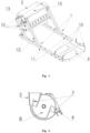
Fig. 1 shows the rotor housing and the base plate for anchoring the motor, which connect the left and right side beams of the frame of the chipper at the mounting points. -
Fig. 2 shows the rotor housing with the rotor and knives in an open side view. -
Fig. 3 shows the open inclined arms of the side beam for fitting of the rotor at its mounting. -
Fig. 4 shows the inclined arms of the side beam connected with the closure after the rotor has been mounted. -
Fig. 5 shows the chipper assembly with the essential components to be protected. - It is understood that the individual embodiments of the invention are presented for purposes of illustration and not as limitations of the solutions.
- In this example of the specific embodiment, the construction of the modular chipper frame according to the invention is described as illustrated in
Fig. 1 . The modular chipper frame is mountable. It comprises twoside beams 1, which at first location are separable connected with therotor housing 2 bymounting elements 10, and at the second location theside beams 1 are separable connected with thebase plate 3 bymounting elements 10 for anchoring themotor 4. Eachside beam 1 is formed, in this specific case, by thelongitudinal profile 11 on which twoinclined arms 12 are fixed for mounting therotor housing 2, which are provided at the top with theseparable closure 13 as shown inFig. 4 . On first face, theside beams 1 are connected by thebumper 17. On the second face, theside beams 1 are connected viabrackets 16 with thehandle 6. - In this example of the specific embodiment, the construction of the chipper itself is described with the modular frame according to the invention included as illustrated in
Fig. 5 . A chipper comprising the modular frame as described in Example 1. The chipper further comprises themotor 4 mounted on thebase plate 3 with the drive to therotor 8, therotor housing 2 with thechip discharge spout 14 and thehopper 5 for loading the wood mass to be chipped. It also has thehandle 6. Therotor housing 2 comprises the cutting device, twochopping knives 7 of which are fixed on therotor 8 and thefixed knife 9 is fixed against therotor housing 2 which is covered by thelid 15 as shown inFigures 1 and4 . The chipper has a variable working width derived from the width of therotor housing 2 and thebase plate 3 for anchoring themotor 4. - The modular frame of the chipper and the chipper itself with the modular frame according to the invention can be used wherever wood or green waste suitable for such processing arises, in particular in gardens, parks, orchards, golf courses, but also in forests.
-
- 1
- side beam
- 2
- rotor housing
- 3
- base plate
- 4
- motor
- 5
- hopper
- 6
- handle
- 7
- chopping knives
- 8
- rotor
- 9
- fixed knife
- 10
- mounting elements
- 11
- longitudinal profile
- 12
- inclined arms
- 13
- closure
- 14
- chip discharge spout
- 15
- rotor housing lid
- 16
- handle bracket
- 17
- bumper
Claims (6)
- A modular chipper frame, characterized in that, it is mountable, comprising two side beams (1) which are separable connected with a rotor housing (2) at first location by mounting elements (10) and at the second location the side beams (1) are separable connected with a base plate (3) by mounting elements (10) for anchoring a motor (4).
- The modular chipper frame according to claim 1, characterized in that, the side beams (1) are connected with a bumper 17 at a first face.
- The modular chipper frame according to any one of the previous claims, characterized in that, the side beams (1) are connected with a handle (6) via brackets (16) of the handle at a second face.
- The modular chipper frame according to any one of the previous claims, characterized in that each side beam (1) is formed by a longitudinal profile (11) on which two inclined arms (12), for attaching the rotor housing (2), are fixed, the said arms (12) are equipped with a separable closure (13) at the top.
- A chipper comprising the modular frame according to any one of the previous claims, characterized in that, it further comprises the motor (4), mounted on the base plate (3), with a rotor drive (8), the rotor housing (2) with an discharge spout (14), a hopper (5) and a handle (6), wherein the rotor housing (2) comprises a cutting device having at least two chopping knives (7) mounted on the rotor (8) and a fixed knife (9) which is mounted on the rotor housing (2).
- The chipper comprising the modular frame according to claim 5, characterized in that, the rotor housing (2) and the base plate (3) for anchoring the motor (4) have a variable working width.
Applications Claiming Priority (1)
| Application Number | Priority Date | Filing Date | Title |
|---|---|---|---|
| SK50038-2023A SK500382023A3 (en) | 2023-06-09 | 2023-06-09 | Modular wood chipper frame and wood chipper |
Publications (1)
| Publication Number | Publication Date |
|---|---|
| EP4474057A1 true EP4474057A1 (en) | 2024-12-11 |
Family
ID=92895822
Family Applications (1)
| Application Number | Title | Priority Date | Filing Date |
|---|---|---|---|
| EP24179753.9A Withdrawn EP4474057A1 (en) | 2023-06-09 | 2024-06-04 | Modular chipper frame and chipper |
Country Status (2)
| Country | Link |
|---|---|
| EP (1) | EP4474057A1 (en) |
| SK (1) | SK500382023A3 (en) |
Citations (7)
| Publication number | Priority date | Publication date | Assignee | Title |
|---|---|---|---|---|
| US5390865A (en) * | 1993-01-05 | 1995-02-21 | Vandermolen; Aldo | Processor for chipping and shredding vegetatation |
| US5680998A (en) | 1996-08-01 | 1997-10-28 | Altec Industries, Inc. | Brush chipping machine with in-line drive system |
| CN203400763U (en) * | 2013-08-13 | 2014-01-22 | 浙江鸿牛工贸有限公司 | Pulverizer for grass and trees |
| CN109433356A (en) * | 2018-10-24 | 2019-03-08 | 扶风永恒农牧机械制造有限责任公司 | A kind of double dynamical branch crushing machine |
| CN215903686U (en) * | 2021-02-05 | 2022-02-25 | 潍坊奥司特工贸有限公司 | Wood grinder |
| CN217594805U (en) * | 2022-07-08 | 2022-10-18 | 陈金海 | Branch and miscellaneous tree is smashed and is used branch chip machine |
| USD967867S1 (en) * | 2019-06-03 | 2022-10-25 | Yongkang Doright Industry & Trade Co., Ltd. | Wood chipper |
-
2023
- 2023-06-09 SK SK50038-2023A patent/SK500382023A3/en unknown
-
2024
- 2024-06-04 EP EP24179753.9A patent/EP4474057A1/en not_active Withdrawn
Patent Citations (7)
| Publication number | Priority date | Publication date | Assignee | Title |
|---|---|---|---|---|
| US5390865A (en) * | 1993-01-05 | 1995-02-21 | Vandermolen; Aldo | Processor for chipping and shredding vegetatation |
| US5680998A (en) | 1996-08-01 | 1997-10-28 | Altec Industries, Inc. | Brush chipping machine with in-line drive system |
| CN203400763U (en) * | 2013-08-13 | 2014-01-22 | 浙江鸿牛工贸有限公司 | Pulverizer for grass and trees |
| CN109433356A (en) * | 2018-10-24 | 2019-03-08 | 扶风永恒农牧机械制造有限责任公司 | A kind of double dynamical branch crushing machine |
| USD967867S1 (en) * | 2019-06-03 | 2022-10-25 | Yongkang Doright Industry & Trade Co., Ltd. | Wood chipper |
| CN215903686U (en) * | 2021-02-05 | 2022-02-25 | 潍坊奥司特工贸有限公司 | Wood grinder |
| CN217594805U (en) * | 2022-07-08 | 2022-10-18 | 陈金海 | Branch and miscellaneous tree is smashed and is used branch chip machine |
Also Published As
| Publication number | Publication date |
|---|---|
| SK500382023A3 (en) | 2024-12-18 |
Similar Documents
| Publication | Publication Date | Title |
|---|---|---|
| US6299082B1 (en) | Waste processing machine | |
| US6036125A (en) | Wood chipper | |
| EP3061581B1 (en) | Crusher | |
| US20100181399A1 (en) | Portable rotary chipper apparatus | |
| US20100294868A1 (en) | Chipper drum with integral blower | |
| US5474241A (en) | Portable apparatus for creating mulch | |
| FI102465B (en) | Appliance for atomizing wood | |
| US5649578A (en) | Wood pulverizer with improved hammers and anvils | |
| EP1724024B1 (en) | Pulverizer | |
| US3593930A (en) | Shredder | |
| EP4474057A1 (en) | Modular chipper frame and chipper | |
| AU3342293A (en) | Tumble grinder with screen portion | |
| US5265811A (en) | Mobile comminuting arrangement for organic waste materials | |
| CS254325B2 (en) | Device for plant material crushing | |
| ES2606775B1 (en) | FOOD SET FOR AGRICULTURAL REMAINING MACHINES | |
| WO2007125557A1 (en) | New knife/crushing unit for agricultural and industrial crushing machines | |
| JP2012191909A (en) | Waste straw shredder | |
| EP4474059A1 (en) | Chipper loading mechanism and chipper | |
| KR20190129442A (en) | Chip crusher | |
| EP1993346B1 (en) | Crushing element for agricultural, industrial and other types of machines | |
| EP0304870A2 (en) | Apparatus for processing material | |
| CN221536904U (en) | Split pin protection device, hammer set, cutter disc and crushing equipment | |
| US20230061196A1 (en) | Wood chipper and system and method for discharge | |
| CN219844142U (en) | Crushing knife set of straw crushing and returning machine | |
| CN219092325U (en) | A prevent axle wind for branch rubbing crusher |
Legal Events
| Date | Code | Title | Description |
|---|---|---|---|
| STAA | Information on the status of an ep patent application or granted ep patent |
Free format text: STATUS: UNKNOWN |
|
| PUAI | Public reference made under article 153(3) epc to a published international application that has entered the european phase |
Free format text: ORIGINAL CODE: 0009012 |
|
| STAA | Information on the status of an ep patent application or granted ep patent |
Free format text: STATUS: THE APPLICATION HAS BEEN PUBLISHED |
|
| AK | Designated contracting states |
Kind code of ref document: A1 Designated state(s): AL AT BE BG CH CY CZ DE DK EE ES FI FR GB GR HR HU IE IS IT LI LT LU LV MC ME MK MT NL NO PL PT RO RS SE SI SK SM TR |
|
| STAA | Information on the status of an ep patent application or granted ep patent |
Free format text: STATUS: THE APPLICATION IS DEEMED TO BE WITHDRAWN |
|
| 18D | Application deemed to be withdrawn |
Effective date: 20250612 |