EP4474053A2 - Integrated biocontainment cell sorter - Google Patents
Integrated biocontainment cell sorter Download PDFInfo
- Publication number
- EP4474053A2 EP4474053A2 EP24195215.9A EP24195215A EP4474053A2 EP 4474053 A2 EP4474053 A2 EP 4474053A2 EP 24195215 A EP24195215 A EP 24195215A EP 4474053 A2 EP4474053 A2 EP 4474053A2
- Authority
- EP
- European Patent Office
- Prior art keywords
- main cabinet
- air
- fan
- biocontainment
- integrated
- Prior art date
- Legal status (The legal status is an assumption and is not a legal conclusion. Google has not performed a legal analysis and makes no representation as to the accuracy of the status listed.)
- Pending
Links
Images


Classifications
-
- G—PHYSICS
- G01—MEASURING; TESTING
- G01N—INVESTIGATING OR ANALYSING MATERIALS BY DETERMINING THEIR CHEMICAL OR PHYSICAL PROPERTIES
- G01N15/00—Investigating characteristics of particles; Investigating permeability, pore-volume or surface-area of porous materials
- G01N15/10—Investigating individual particles
- G01N15/14—Optical investigation techniques, e.g. flow cytometry
- G01N15/1456—Optical investigation techniques, e.g. flow cytometry without spatial resolution of the texture or inner structure of the particle, e.g. processing of pulse signals
- G01N15/1459—Optical investigation techniques, e.g. flow cytometry without spatial resolution of the texture or inner structure of the particle, e.g. processing of pulse signals the analysis being performed on a sample stream
-
- G—PHYSICS
- G01—MEASURING; TESTING
- G01N—INVESTIGATING OR ANALYSING MATERIALS BY DETERMINING THEIR CHEMICAL OR PHYSICAL PROPERTIES
- G01N15/00—Investigating characteristics of particles; Investigating permeability, pore-volume or surface-area of porous materials
- G01N15/10—Investigating individual particles
- G01N15/14—Optical investigation techniques, e.g. flow cytometry
- G01N15/149—Optical investigation techniques, e.g. flow cytometry specially adapted for sorting particles, e.g. by their size or optical properties
- G01N15/1492—Optical investigation techniques, e.g. flow cytometry specially adapted for sorting particles, e.g. by their size or optical properties within droplets
-
- B—PERFORMING OPERATIONS; TRANSPORTING
- B01—PHYSICAL OR CHEMICAL PROCESSES OR APPARATUS IN GENERAL
- B01L—CHEMICAL OR PHYSICAL LABORATORY APPARATUS FOR GENERAL USE
- B01L1/00—Enclosures; Chambers
- B01L1/02—Air-pressure chambers; Air-locks therefor
- B01L1/025—Environmental chambers
-
- G—PHYSICS
- G01—MEASURING; TESTING
- G01N—INVESTIGATING OR ANALYSING MATERIALS BY DETERMINING THEIR CHEMICAL OR PHYSICAL PROPERTIES
- G01N1/00—Sampling; Preparing specimens for investigation
- G01N1/02—Devices for withdrawing samples
- G01N1/22—Devices for withdrawing samples in the gaseous state
-
- G—PHYSICS
- G01—MEASURING; TESTING
- G01N—INVESTIGATING OR ANALYSING MATERIALS BY DETERMINING THEIR CHEMICAL OR PHYSICAL PROPERTIES
- G01N15/00—Investigating characteristics of particles; Investigating permeability, pore-volume or surface-area of porous materials
- G01N15/01—Investigating characteristics of particles; Investigating permeability, pore-volume or surface-area of porous materials specially adapted for biological cells, e.g. blood cells
-
- G—PHYSICS
- G01—MEASURING; TESTING
- G01N—INVESTIGATING OR ANALYSING MATERIALS BY DETERMINING THEIR CHEMICAL OR PHYSICAL PROPERTIES
- G01N15/00—Investigating characteristics of particles; Investigating permeability, pore-volume or surface-area of porous materials
- G01N15/10—Investigating individual particles
- G01N15/14—Optical investigation techniques, e.g. flow cytometry
- G01N15/1404—Handling flow, e.g. hydrodynamic focusing
- G01N15/1409—Handling samples, e.g. injecting samples
-
- G—PHYSICS
- G01—MEASURING; TESTING
- G01N—INVESTIGATING OR ANALYSING MATERIALS BY DETERMINING THEIR CHEMICAL OR PHYSICAL PROPERTIES
- G01N15/00—Investigating characteristics of particles; Investigating permeability, pore-volume or surface-area of porous materials
- G01N15/10—Investigating individual particles
- G01N15/14—Optical investigation techniques, e.g. flow cytometry
- G01N15/1434—Optical arrangements
-
- B—PERFORMING OPERATIONS; TRANSPORTING
- B01—PHYSICAL OR CHEMICAL PROCESSES OR APPARATUS IN GENERAL
- B01L—CHEMICAL OR PHYSICAL LABORATORY APPARATUS FOR GENERAL USE
- B01L2200/00—Solutions for specific problems relating to chemical or physical laboratory apparatus
- B01L2200/14—Process control and prevention of errors
- B01L2200/141—Preventing contamination, tampering
-
- G—PHYSICS
- G01—MEASURING; TESTING
- G01N—INVESTIGATING OR ANALYSING MATERIALS BY DETERMINING THEIR CHEMICAL OR PHYSICAL PROPERTIES
- G01N15/00—Investigating characteristics of particles; Investigating permeability, pore-volume or surface-area of porous materials
- G01N15/10—Investigating individual particles
- G01N15/14—Optical investigation techniques, e.g. flow cytometry
- G01N15/149—Optical investigation techniques, e.g. flow cytometry specially adapted for sorting particles, e.g. by their size or optical properties
-
- G—PHYSICS
- G01—MEASURING; TESTING
- G01N—INVESTIGATING OR ANALYSING MATERIALS BY DETERMINING THEIR CHEMICAL OR PHYSICAL PROPERTIES
- G01N1/00—Sampling; Preparing specimens for investigation
- G01N1/02—Devices for withdrawing samples
- G01N1/22—Devices for withdrawing samples in the gaseous state
- G01N1/2202—Devices for withdrawing samples in the gaseous state involving separation of sample components during sampling
- G01N2001/222—Other features
- G01N2001/2223—Other features aerosol sampling devices
-
- G—PHYSICS
- G01—MEASURING; TESTING
- G01N—INVESTIGATING OR ANALYSING MATERIALS BY DETERMINING THEIR CHEMICAL OR PHYSICAL PROPERTIES
- G01N15/00—Investigating characteristics of particles; Investigating permeability, pore-volume or surface-area of porous materials
- G01N2015/0019—Means for transferring or separating particles prior to analysis, e.g. hoppers or particle conveyors
-
- G—PHYSICS
- G01—MEASURING; TESTING
- G01N—INVESTIGATING OR ANALYSING MATERIALS BY DETERMINING THEIR CHEMICAL OR PHYSICAL PROPERTIES
- G01N15/00—Investigating characteristics of particles; Investigating permeability, pore-volume or surface-area of porous materials
- G01N15/10—Investigating individual particles
- G01N2015/1006—Investigating individual particles for cytology
-
- G—PHYSICS
- G01—MEASURING; TESTING
- G01N—INVESTIGATING OR ANALYSING MATERIALS BY DETERMINING THEIR CHEMICAL OR PHYSICAL PROPERTIES
- G01N35/00—Automatic analysis not limited to methods or materials provided for in any single one of groups G01N1/00 - G01N33/00; Handling materials therefor
- G01N2035/00178—Special arrangements of analysers
- G01N2035/00277—Special precautions to avoid contamination (e.g. enclosures, glove- boxes, sealed sample carriers, disposal of contaminated material)
Definitions
- Cell sorter flow cytometers have become an important laboratory tool.
- Cell sorters are capable of identifying certain types of biological cells and separating those cells from other cells.
- Commercial uses of cell sorters have also been implemented in several industries. There are many other uses of cell sorters, such as identifying and isolating various types of cells for laboratory applications. As such, cell sorters have many different and varied uses and applications.
- An embodiment of the present invention my therefore comprise an integrated biocontainment cell sorter flow cytometer comprising: a main cabinet of the integrated biocontainment cell sorter that is not hermetically sealed; an input sample area disposed in the main cabinet; a moveable partition in the main cabinet that moves in an access opening of the main cabinet, the moveable partition covering a constant amount of area of the access opening as the moveable partition is moved in the access opening which leaves a constant amount of area of the access opening that is not covered by the moveable partition and is open, as the moveable partition is moved in the access opening; a first fan that draws air from the main cabinet to create a first low pressure in the main cabinet that is substantially constant as the moveable partition is moved in the access opening, which limits contaminated air in the main cabinet from escaping from the main cabinet; an aerosol management containment area that is not hermetically sealed, which is disposed in the main cabinet, the aerosol management containment area having openings that are connected to the main cabinet so that the aerosol management containment area is disposed in
- Another embodiment of the present invention may therefore comprise a method of containing cells in an integrated biocontainment cell sorter comprising: providing a main cabinet containment area that contains an input area for sample cells to be sorted; generating a first low pressure in the main cabinet using a first fan that draws air from the main cabinet and air from outside the cabinet; generating a second low pressure in an aerosol management containment area, disposed in the main cabinet, using a second fan that draws air from the main cabinet and the aerosol management containment area through openings in the aerosol management containment area to create the second low pressure in the aerosol management containment area that is lower than the first low pressure; enclosing input cell samples in the main cabinet that is not hermetically sealed; enclosing a nozzle, sort plates, collection media and any droplet stream, created by the nozzle, in an aerosol management containment area that is not hermetically sealed; locating optical excitation devices outside of the main cabinet and the aerosol management containment area for easy access for adjustment and maintenance of the optical excitation devices
- the present invention is also defined by the following numbered embodiments.
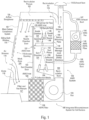
- FIG. 1 is a schematic diagram of one embodiment of an integrated biocontainment system 100.
- the system is comprised of a main cabinet containment system 101 and aerosol management system chambers 140, the AMS intake duct 138, AMS HEPA filter 141, AMS fan 144 and AMS exhaust duct 147, which are collectively referred to as the aerosol management system (AMS) 149.
- the aerosol management system (AMS) 149 is contained in or connected to the main cabinet containment system 101. Neither the main cabinet containment system 101 nor the aerosol management system (AMS) 149 are sealed systems.
- AMS aerosol management system
- Dangerous materials primarily exist as aerosols that contain sample cells.
- Sample cells are mixed with sheath fluid and passed through a nozzle 146.
- the nozzle creates a nozzle stream 153 ( Figure 2 ) that breaks up into a droplet stream 155 ( Figure 2 ). If the nozzle becomes clogged, an aerosol can be created that contains sample cells. Also, if the nozzle stream 153 or the droplet stream 155 hit a hard surface, aerosols can be created.
- the aerosols contain sample cells that should not be inhaled or ingested.
- the sample cells may be cancer cells.
- air drawn by the fan 122 first passes through the HEPA filter 120 to remove any dangerous materials such as sample cells. Consequently, the air drawn by the fan 122 is clean air and the fan is not contaminated.
- the fan 122 forces the clean air through the recirculation duct 108 under positive pressure, which also remains clean.
- the recirculation duct 108 and recirculation plenum do not have to be sealed, even though they are under positive pressure, since they contain clean air.
- Part of the air from the fan 122 is exhausted out of the exhaust vent 110, as illustrated by exhaust air 126. At the same time, some of the air from the fan 122 is recirculated, as illustrated by recirculation air 124.
- the recirculation duct 108 circulates clean air under positive pressure, and clean air is recirculated into the recirculation plenum 102 under positive pressure, while the remaining air is exhausted out of the exhaust vent 110.
- the recirculated air in the recirculation duct 108 and the recirculation plenum 102 is under positive pressure and as such may leak from these ducts to the outside air or to other parts of the integrated biocontainment system 100. Since the air under positive pressure is clean air, there are no problems with contamination, unlike many other containment systems.
- the recirculated air in the recirculation plenum 102 passes through an airflow straightener 128.
- the airflow straightener 128 is a device that has openings that cause the recirculated air to flow into the work area 104 as a substantially uniform, laminar air flow 130 with low turbulence. Low turbulence allows for maintenance of a uniform downward volume of air that prevents both contaminates from the inside of the cabinet from escaping the user access opening and prevents contaminates from the outside of the cabinet from depositing on the products present inside the cabinet.
- the aerosol management system chambers 140 have openings that connect to the main cabinet containment system 101, as also illustrated in Figure 1 .
- the aerosol management system (AMS) 149 has a separate AMS HEPA filter 141 and a separate AMS fan 144.
- AMS fan 144 draws air from the AMS intake duct 138, which is connected to the sort chamber 131. Since the aerosol management system chambers 140 are connected by openings to the main cabinet containment system 101, the aerosol management system chambers 140 are already at the first low pressure that is maintained in the main cabinet containment system 101.
- AMS fan 144 further lowers the pressure in the aerosol management system (AMS) 149 from the first low pressure of the work area 104 to a second low pressure that is lower than the first low pressure.
- the second low pressure in the aerosol management system chambers 140 will equalize with the first low pressure of the main cabinet containment system 101. So, as the pressures of the main cabinet containment system 101 and the aerosol management system chambers 140 equalize as a result of either the nozzle chamber door 136 or the sort chamber door 132 being opened, air initially flows from the main cabinet containment system 101 to the aerosol management system chambers 140 which prevents aerosols from escaping the aerosol management system chambers 140. However, once the pressures are equalized, there can be a migration of aerosols from the aerosol management system chambers 140 to the main cabinet containment system 101.
- the nozzle 146 is shut down and the AMS fan 144 is operated at an increased speed for a time to evacuate all aerosols from the aerosol management system chambers 140.
- the aerosol management system (AMS) 149 is not only a parallel containment system to the main cabinet containment system 101, the aerosol management system chambers 140 are connected by air inlets to the main cabinet containment system 101 to create a second lower pressure, which makes it doubly hard for dangerous materials located in the aerosol management system chambers 140 and the work area 104 to escape from the integrated biocontainment system 100.
- the aerosol management system chambers 140 are carefully constructed to enclose portions of the cell sorter that produce hazardous particles and not enclose portions of the cell sorter that do not produce hazardous particles, to minimize the size of the containment area and consequently minimize the size of the integrated biocontainment system 100 for cell sorters.
- the nozzle chamber 134 contains the nozzle 146 which is fed sample fluid 143 and sheath fluid 145.
- the nozzle 146 creates a nozzle stream 153 ( Figure 2 ) from the sample fluid 143 and sheath fluid 145 that passes through the interrogation point 148 and through an opening 152 in the optics mounting plate 150.
- the nozzle 146 is contained within the nozzle chamber 134 to prevent any dangerous aerosols from escaping the aerosol management system chambers 140.
- the optics mounting plate 150 separates the nozzle chamber 134 from the sort chamber 131. Opening 152 allows the interrogated droplet stream 155 ( Figure 2 ) to pass through the optics mounting plate 150 to the sort plates 154. Each droplet of the droplet stream 155 ( Figure 2 ) that is interrogated at interrogation point 148 is then separated by the sort plates 154.
- the deflected droplet streams 156 are then collected by the collection media 158. This is explained in more detail in U.S. Patent 8,557,587 issued on October 15, 2013 to Fox et al. , which is specifically incorporated herein, by reference, for all that it discloses and teaches.
- the main cabinet containment system 101 is primarily used to contain the sample input area 107 ( Figure 5 ) from the ambient air outside of the main cabinet containment system
- the main cabinet containment system 101 may therefore contain dangerous cells in the sample input area 107.
- the partition 114 which may comprise a transparent sliding sash window, allows an operator to easily access the sample input area and the sort chamber 131, through the sort chamber door 132 when the partition 114 is in an upper position in the access opening 115, as shown in Figure 1 , to insert and remove samples in the sample input area 107 ( Figure 5 ).
- the partition 114 can be moved to a lower position in the access opening 115 to allow direct access by an operator to the nozzle chamber 134, through nozzle chamber door 136.
- Fan 122 is sufficiently strong to maintain a low pressure in the work area 104 even though the access opening is only partially covered by the partition 114.
- the partition 114 can simply move up and down in the access opening 115. Accordingly, the amount of area that is closed or blocked off in the access opening 115 by the partition 114 and the amount of area that is open in the access opening 115, and is not closed or blocked off by partition 114, does not change no matter where the partition 114 is placed in the access opening 115. In other words, the same amount of open area of the access opening 115 is present no matter where the partition 114 is located in the access opening 115.
- a certain number of square inches of opening in the access opening 115 are present.
- the partition 114 is moved downwardly, the amount of open area in the access opening 115 has a constant size, i.e.
- the partition 114 has a constant size and the access opening 115 has a constant size.
- the amount of air that is transported by fan 122 can remain the same no matter where the partition 114 is located and still maintain a constant first low pressure in the work area 104.
- the fan 122 moves about 100 feet of air per minute through the user access opening 115 into the work area 104.
- the integrated biocontainment cell sorter system is based on the velocity of the air that moves through the cabinet. The velocity of the air must be fast enough in order to maintain containment since the integrated biocontainment cell sorter is not a sealed system.
- the air speed of the air that enters the grate 118 is measured to ensure proper velocity to maintain containment.
- the fan 122 is designed to operate so that the volume of air that passes through the grate 118 is sufficient to maintain the containment of hazardous materials in the main cabinet containment system 101.
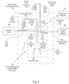
- FIG 2 is a schematic diagram illustrating portions of the aerosol management system (AMS) 149.
- Figure 2 specifically illustrates the portions of the cell sorter that are contained within the aerosol management system chambers 140.
- the nozzle 186, as well as the connecting tubing, are located in the nozzle chamber 134.
- the sort plates 176, collection tubes 182, 184 are located in the sort chamber 131. Opening 174 allows the droplet stream 155 to flow from the nozzle chamber 134 to the sort chamber 131 through the optics mounting plate 150 ( Figure 3 ).
- Figure 2 illustrates the primary components that are located within the nozzle chamber 134 and the sort chamber 131 that comprise the aerosol management system chambers
- the aerosol management system chambers 140 surround the sort plates, collection tubes 182, 184 and the deflected droplet streams 156.
- the nozzle chamber 134 and the sort chamber 131, as well as the opening 174 between these two chambers, comprise the aerosol management system chambers 140.
- the nozzle 186, the opening 174, the sort plates 176 and the collection tubes 182, 184 are the primary functional components that are contained within the aerosol management system chambers 140.
- the sample fluid container 172 which is placed in the sample input area 107 ( Figure 5 ) opens into the main cabinet containment system 101, and not in the aerosol management system chambers 140.
- the sheath fluid container 170, the excitation optics 162, the forward scatter detector 180 and the side scatter detector 178 are preferably all located outside of the main cabinet containment system 101.
- the side scatter light path 168 and the forward scatter light path 166 project light through an optical window, as illustrated in Figure 4 , to side scatter detector 178 and forward scatter detector 180, respectively.
- Other electronics and controllers, as well as lasers, are preferably located outside of the main cabinet containment system 101. For example, as disclosed in U.S.
- Patent 8,557,587 which is specifically incorporated herein by reference, for all that it discloses and teaches, timing and charge circuits, sort logic controllers, optical filters, detectors, acquisition electronics, and other electronic circuits and devices, collectively defined herein as cell sorter electronics and optical devices, are preferably all located outside of the main cabinet and the aerosol management containment area for easy access for maintenance and adjustment.
- the cell sorter electronics and optical devices are preferably located in areas that are easily accessed, and do not require access to contaminated areas within the main cabinet containment system 101 or the aerosol management system chambers 140. Consequently, the excitation optics 162, the side scatter detector 178 and the forward scatter detector 180 can preferably be easily accessed without accessing a biocontainment area.
- these devices need adjustment, and the accessibility of these devices, without the necessity of entering a dirty or biocontainment area, greatly increases the speed and maintenance of the system.
- the excitation optics 162 comprises the excitation lasers or other excitation optics such as LEDs, optically pumped plasma light generators, arc lamps or other excitation optics.
- the optics include the various mirrors, beam combiners, lenses, etc. Accordingly, the present invention, in accordance with one embodiment, may simply have the excitation optics 162 located outside of the main cabinet and the other portions, such as the side scatter detector 178, forward scatter detector 180, and other devices located inside of the main cabinet 101 and aerosol management system chambers 140.
- the optical detection devices such as side scatter detector 178 and forward scatter detector 180, may also be located outside of the main cabinet 101 along with the excitation optics 162, in accordance with another embodiment of the present invention, and as illustrated in Figure 2 .
- the fluidics such as the sheath fluid container 170, the various pumps associated with the sheath fluid, may also be located outside of either the aerosol management system chambers 140, or the main cabinet containment system 101, either individually or collectively.
- various combinations of equipment can be located outside of the main cabinet 101 and/or the aerosol management system chambers 140 to increase accessibility and increase the ease of maintenance of various systems and also reduce the size of the containment area.
- the volume of the main cabinet containment system 101 is greatly decreased.
- Many cell sorter systems are simply placed in a containment hood, which is very large and bulky.
- containment hoods are typically about nine feet high and can be six or seven feet wide.
- sample fluid container 172 By containing sample fluid container 172 in the input sample area 107, which is adjacent to the work area 104 of the main cabinet containment system 101, input fluids can be easily inserted and removed from the input sample area 107 since the sample fluid container 172 does not impose as much of a hazard as aerosols that can be created in the nozzle chamber 134 and the sort chamber 131.
- aerosol management system chambers 140 having openings to main cabinet containment system 101 provides additional safety for the operators since they are not subjected to any of the hazardous particles that are contained in the aerosols of the aerosol management system chambers 140.
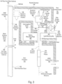
- FIG 3 is a schematic cutaway side view of the aerosol management system chambers 140.
- the nozzle chamber 134 contains the nozzle 186, which is illustrated in solid lines in the operating position. Sheath fluid 170 is provided through the nozzle 186, as well as the sample fluid 172.
- the nozzle 186 can also be moved to a cleaning position, as illustrated in dotted lines.
- the nozzle chamber door 198 can be opened so that the nozzle 186, in the cleaning position, is accessible through the nozzle chamber door 198. Nozzles, such as nozzle 186, can become clogged for various reasons, and a quick and easy access to the nozzle 186 is provided when the nozzle 186 is in the cleaning position.
- the negative pressure in the nozzle chamber 134 compared to the main work area 104, is equalized so that contaminated air can at that point in time migrate from the nozzle chamber 134 to the main work area 104.
- the droplet stream 155 from the nozzle 186 flows through an opening 152 and the optics mounting plate 150.
- the droplet stream 155 passes through an interrogation point 148 prior to the droplets separating from the stream.
- Laser beams interrogate the nozzle stream 153 at the interrogation point 148. Scattered and projected light from the interrogation point 148 is transmitted through the optical window 200 and past the light blocking bar 202 to a side scatter objective 204.
- Side scatter objective 204 collects the side scatter rays and transmits those rays through side scatter pin hole 206.
- Flexible seals 210, 212 and 214 provide a partial seal so that the droplet stream 155 does not transfer to the non-containment air 208.
- the droplet stream 155 passes through the sort plates 154 and is separated into deflected droplet streams 156.
- the AMS intake duct 138 is connected to the AMS HEPA filter 141 and the AMS fan 144, as illustrated in Figure 1 . Air from the sort chamber 131 is drawn through the AMS intake duct 138 to create a low pressure in both the sort chamber 131 and the nozzle chamber 134. Air from the main cabinet work area 104 passes through inlets 188 and 194.
- Airflow 190 from the main cabinet passes through inlet 188, while airflow 196 from the main cabinet passes through inlet 194.
- the sort chamber 131 has a sort chamber door 132 that can be opened to provide operator access to the sort plates 154 and collection tubes 182, 184 ( Figure 2 ) in the sort chamber 131. Again, because the sort chamber 131 has lower pressure than the main cabinet work area 104, opening of the sort chamber door 132 equalizes the pressure of the sort chamber and the main cabinet work area 104. To prevent hazardous aerosols from escaping the sort chamber 131 or nozzle chamber 134, both the sort chamber 131 and the nozzle chamber 134 must be evacuated using the AMS fan 144 ( Figure 1 ) prior to opening either the nozzle chamber door 198 or the sort chamber door 132. Once the aerosols are purged from the aerosol management chambers 140, the doors 198, 132 can be opened.
- Figure 4 is a front schematic view illustrating the nozzle chamber 134, the sort chamber 131 and various devices of the cell sorter that are located outside of the aerosol management system (AMS) 149 and the main cabinet containment system 101. As illustrated in Figure 4 , non-containment air 208 surrounds the nozzle chamber wall 213 of the nozzle chamber
- FIG. 5 is a perspective view of an embodiment of an implementation of the integrated biocontainment cell sorter 100.
- an exhaust vent 110 exhausts clean air out of the integrated biocontainment cell sorter 100.
- Clean air is provided to the recirculation plenum 102 by the recirculation duct 108.
- the filter and fan plenum 121 contain the filter and fan in a location that is in the back and the bottom of the integrated biocontainment cell sorter 100 so that other portions of the integrated biocontainment cell sorter 100 are easily accessible to an operator.
- Sliding sash window (partition) 114 moves with an angular vertical movement to provide an opening to the main cabinet containment system 101.
- the sample input area 107 is accessible by an operator.
- the nozzle chamber 134 and sample line are accessible.
- Grate 118 allows air from outside of the integrated biocontainment cell sorter 100 to be drawn into the main cabinet containment system 101 so that contaminated air does not pass out of the main cabinet containment system 101. By maintaining a lower pressure in the main cabinet containment system 101, contaminated air does not escape from the integrated biocontainment cell sorter 100.
- the integrated biocontainment cell sorter 100 provides containment only around the portions of the cell sorter that may create contaminated air.
- the integrated biocontainment cell sorter 100 has containment areas that are small and compact, have smaller fans and substantially smaller overall dimensions than cell sorters that are placed in large hoods or partially integrated biocontainment cell sorters.
- Partially integrated biocontainment cell sorters encapsulate numerous components of a cell sorter that do not require containment, and make it much more difficult to provide maintenance to specific areas of the cell sorter that do not require biocontainment.
- the smaller containment areas results in smaller fans and requires moving a reduced volume of air to maintain containment, thereby saving energy.
Landscapes
- Chemical & Material Sciences (AREA)
- Health & Medical Sciences (AREA)
- Life Sciences & Earth Sciences (AREA)
- Pathology (AREA)
- Analytical Chemistry (AREA)
- Biochemistry (AREA)
- General Health & Medical Sciences (AREA)
- General Physics & Mathematics (AREA)
- Immunology (AREA)
- Physics & Mathematics (AREA)
- Dispersion Chemistry (AREA)
- Biomedical Technology (AREA)
- Molecular Biology (AREA)
- Engineering & Computer Science (AREA)
- Chemical Kinetics & Catalysis (AREA)
- Clinical Laboratory Science (AREA)
- Apparatus Associated With Microorganisms And Enzymes (AREA)
- Sampling And Sample Adjustment (AREA)
- Devices For Use In Laboratory Experiments (AREA)
- Ventilation (AREA)
- Filtering Of Dispersed Particles In Gases (AREA)
Abstract
Description
- Cell sorter flow cytometers have become an important laboratory tool. Cell sorters are capable of identifying certain types of biological cells and separating those cells from other cells. Commercial uses of cell sorters have also been implemented in several industries. There are many other uses of cell sorters, such as identifying and isolating various types of cells for laboratory applications. As such, cell sorters have many different and varied uses and applications.
- An embodiment of the present invention my therefore comprise an integrated biocontainment cell sorter flow cytometer comprising: a main cabinet of the integrated biocontainment cell sorter that is not hermetically sealed; an input sample area disposed in the main cabinet; a moveable partition in the main cabinet that moves in an access opening of the main cabinet, the moveable partition covering a constant amount of area of the access opening as the moveable partition is moved in the access opening which leaves a constant amount of area of the access opening that is not covered by the moveable partition and is open, as the moveable partition is moved in the access opening; a first fan that draws air from the main cabinet to create a first low pressure in the main cabinet that is substantially constant as the moveable partition is moved in the access opening, which limits contaminated air in the main cabinet from escaping from the main cabinet; an aerosol management containment area that is not hermetically sealed, which is disposed in the main cabinet, the aerosol management containment area having openings that are connected to the main cabinet so that the aerosol management containment area is disposed in and subject to the first low pressure, the aerosol management containment area having a nozzle that creates a droplet stream containing sample cells, sort plates that separate the droplet stream into deflected stream and collection media, that collect the deflected streams; a second fan that draws air from the aerosol management containment area to create a second low pressure in the aerosol management containment area that is lower than the first low pressure which causes air from the main cabinet to flow from the main cabinet to the aerosol management containment area and limits contaminated air from flowing from the aerosol management containment area into the main cabinet; optical excitation devices located outside of the main cabinet and the aerosol management containment area to allow access to the optical excitement devices without accessing the main cabinet or the aerosol management containment area.
- Another embodiment of the present invention may therefore comprise a method of containing cells in an integrated biocontainment cell sorter comprising: providing a main cabinet containment area that contains an input area for sample cells to be sorted; generating a first low pressure in the main cabinet using a first fan that draws air from the main cabinet and air from outside the cabinet; generating a second low pressure in an aerosol management containment area, disposed in the main cabinet, using a second fan that draws air from the main cabinet and the aerosol management containment area through openings in the aerosol management containment area to create the second low pressure in the aerosol management containment area that is lower than the first low pressure; enclosing input cell samples in the main cabinet that is not hermetically sealed; enclosing a nozzle, sort plates, collection media and any droplet stream, created by the nozzle, in an aerosol management containment area that is not hermetically sealed; locating optical excitation devices outside of the main cabinet and the aerosol management containment area for easy access for adjustment and maintenance of the optical excitation devices.
- The present invention is also defined by the following numbered embodiments.
- 1. An integrated biocontainment cell sorter flow cytometer comprising:
- a main cabinet of said integrated biocontainment cell sorter that is not hermetically sealed;
- an input sample area disposed in said main cabinet;
- a moveable partition in said main cabinet that moves in an access opening of said main cabinet, said moveable partition covering a constant amount of area of said access opening as said moveable partition is moved in said access opening which leaves a constant amount of area of said access opening that is not covered by said moveable partition and is open, as said moveable partition is moved in said access opening;
- a first fan that draws air from said main cabinet to create a first low pressure in said main cabinet that is substantially constant as said moveable partition is moved in said access opening, which limits contaminated air in said main cabinet from escaping from said main cabinet;
- an aerosol management containment area that is not hermetically sealed, which is disposed in said main cabinet, said aerosol management containment area having openings that are connected to said main cabinet so that said aerosol management containment area is disposed in and subject to said first low pressure, said aerosol management containment area having a nozzle that creates a droplet stream containing sample cells, sort plates that separate said droplet stream into deflected stream and collection media, that collect said deflected streams;
- a second fan that draws air from said aerosol management containment area to create a second low pressure in said aerosol management containment area that is lower than said first low pressure which causes air from said main cabinet to flow from said main cabinet to said aerosol management containment area and limits contaminated air from flowing from said aerosol management containment area into said main cabinet;
- optical excitation devices located outside of said main cabinet and said aerosol management containment area to allow access to said optical excitement devices without accessing said main cabinet or said aerosol management containment area.
- 2. The integrated biocontainment cell sorter of embodiment 1 wherein:
said moveable partition is a slideable window. - 3. The integrated biocontainment cell sorter of embodiment 1 wherein said optical excitation devices comprise lasers and excitation optics.
- 4. The integrated biocontainment cell sorter of embodiment 3 wherein detector optics, optical filters, timing and charge circuits and sort logic controllers are located outside of said main cabinet.
- 5. The integrated biocontainment cell sorter of embodiment 3 wherein fluidics are located outside of said main cabinet.
- 6. The integrated biocontainment cell sorter of embodiment 5 wherein said fluidics comprise sheath fluid controllers and nozzle cleaning devices.
- 7. The integrated biocontainment sorter of embodiment 2 further comprising:
- a first HEPA filter located adjacent to a main work area of said main cabinet and upstream from said first fan so that said fan circulates clean air and is not contaminated;
- a second HEPA filter located adjacent to said aerosol management containment area and upstream from a second fan so that said second fan is not contaminated and removes air from said aerosol management containment area, which is cleaned by said second HEPA filter, and moves clean air to an exhaust vent.
- 8. A method of containing cells in an integrated biocontainment cell sorter comprising:
- providing a main cabinet containment area that contains an input area for sample cells to be sorted;
- generating a first low pressure in said main cabinet using a first fan that draws air from said main cabinet and air from outside said cabinet;
- generating a second low pressure in an aerosol management containment area, disposed in said main cabinet, using a second fan that draws air from said main cabinet and said aerosol management containment area through openings in said aerosol management containment area to create said second low pressure in said aerosol management containment area that is lower than said first low pressure;
- enclosing input cell samples in said main cabinet that is not hermetically sealed;
- enclosing a nozzle, sort plates, collection media and any droplet stream, created by said nozzle, in an aerosol management containment area that is not hermetically sealed;
- locating optical excitation devices outside of said main cabinet and said aerosol management containment area for easy access for adjustment and maintenance of said optical excitation devices.
- 9. The method of embodiment 8 wherein said method of locating optical excitation devices outside of said main cabinet comprises locating lasers and laser optics outside of said main cabinet.
- 10. The method of embodiment 8 further comprising:
locating detector optics, optical filters, timing and charge circuits, acquisition electronics and sort logic controllers outside of said main cabinet. - 11. The method of embodiment 8 further comprising:
locating fluidics outside of said main cabinet. - 12. The method of embodiment 11 wherein said method of locating said fluidics outside of said main cabinet comprises:
locating sheath fluid controllers and nozzle cleaning devices outside of said main cabinet. - 13. The method of embodiment 8 further comprising:
using a moveable partition in an access opening of said main cabinet that covers an area of said access opening so that a constant amount of area of said access opening is not covered by said moveable partition which remains constant as said moveable partition is moved in said access opening, which causes said first low pressure to remain constant as said moveable partition is moved in said access opening. - 14. The method of embodiment 13 wherein said moveable partition is transparent and moves to allow access to lower portions of said main cabinet when said moveable partition is in an upper position, and moves to allow access to upper portions of said main cabinet when said moveable partition is in a lower position.
- 15. The method of containing cells of embodiment 8 further comprising:
filtering said outside air and said air from said main cabinet upstream from said first fan so that said first fan is not contaminated and air under pressure from said first fan is clean air that can be circulated in said integrated biocontainment cell sorter without contamination. - 16. The method of containing cells of embodiment 8 further comprising:
filtering air drawn from said aerosol management containment area upstream from said second fan so that said second fan is not contaminated and clean air under pressure from said second fan is transmitted through said integrated biocontainment cell sorter and exhausted without contamination. -
-
Figure 1 is a schematic side cutaway view illustrating various parts of one embodiment of an integrated biocontainment cell sorter. -
Figure 2 is a schematic illustration of the Aerosol Management System (AMS) ofFigure 1 , including the nozzle chamber and sort chamber and various other parts of an embodiment of an integrated biocontainment cell sorter. -
Figure 3 is a more detailed side cutaway view illustrating the nozzle chamber and the sort chamber ofFigure 2 . -
Figure 4 is a detailed front view of an embodiment of an integrated biocontainment cell sorter showing the nozzle chamber and sort chamber ofFigures 2 and3 . -
Figure 5 is a perspective view of an implementation of the integrated biocontainment cell sorter that is illustrated inFigures 1-4 . -
Figure 1 is a schematic diagram of one embodiment of anintegrated biocontainment system 100. The system is comprised of a maincabinet containment system 101 and aerosolmanagement system chambers 140, theAMS intake duct 138, AMS HEPA filter 141,AMS fan 144 and AMS exhaust duct 147, which are collectively referred to as the aerosol management system (AMS) 149. The aerosol management system (AMS) 149 is contained in or connected to the maincabinet containment system 101. Neither the maincabinet containment system 101 nor the aerosol management system (AMS) 149 are sealed systems. Rather, they rely on movement of air byfan 122, in the maincabinet containment system 101, andAMS fan 144 in the aerosol management system (AMS) 149, to create low pressure, so that harmful and toxic materials are not spread outside of each of these containment systems. For example, a first low pressure is created in thework area 104 of the maincabinet containment system 101 as a result offan 122 extracting air from both thework area 104 and air from outside of the maincabinet containment system 101, which is shown by air streams 116. In this manner, a first low pressure is created in thework area 104 where potentially toxic or dangerous materials may exist. As long as thefan 122 is able to pull sufficient air through thework area 104, dangerous materials will not escape from thework area 104 to an area outside the maincabinet containment system 101. Dangerous materials primarily exist as aerosols that contain sample cells. Sample cells are mixed with sheath fluid and passed through anozzle 146. Normally, the nozzle creates a nozzle stream 153 (Figure 2 ) that breaks up into a droplet stream 155 (Figure 2 ). If the nozzle becomes clogged, an aerosol can be created that contains sample cells. Also, if thenozzle stream 153 or thedroplet stream 155 hit a hard surface, aerosols can be created. The aerosols contain sample cells that should not be inhaled or ingested. For example, the sample cells may be cancer cells. - As also shown in
Figure 1 , air drawn by thefan 122 first passes through theHEPA filter 120 to remove any dangerous materials such as sample cells. Consequently, the air drawn by thefan 122 is clean air and the fan is not contaminated. Thefan 122 forces the clean air through therecirculation duct 108 under positive pressure, which also remains clean. Therecirculation duct 108 and recirculation plenum do not have to be sealed, even though they are under positive pressure, since they contain clean air. Part of the air from thefan 122 is exhausted out of the exhaust vent 110, as illustrated byexhaust air 126. At the same time, some of the air from thefan 122 is recirculated, as illustrated byrecirculation air 124. Hence, therecirculation duct 108 circulates clean air under positive pressure, and clean air is recirculated into therecirculation plenum 102 under positive pressure, while the remaining air is exhausted out of the exhaust vent 110. The recirculated air in therecirculation duct 108 and therecirculation plenum 102 is under positive pressure and as such may leak from these ducts to the outside air or to other parts of theintegrated biocontainment system 100. Since the air under positive pressure is clean air, there are no problems with contamination, unlike many other containment systems. The recirculated air in therecirculation plenum 102 passes through anairflow straightener 128. Theairflow straightener 128 is a device that has openings that cause the recirculated air to flow into thework area 104 as a substantially uniform,laminar air flow 130 with low turbulence. Low turbulence allows for maintenance of a uniform downward volume of air that prevents both contaminates from the inside of the cabinet from escaping the user access opening and prevents contaminates from the outside of the cabinet from depositing on the products present inside the cabinet. - The aerosol
management system chambers 140 have openings that connect to the maincabinet containment system 101, as also illustrated inFigure 1 . The aerosol management system (AMS) 149 has a separate AMS HEPA filter 141 and aseparate AMS fan 144.AMS fan 144 draws air from theAMS intake duct 138, which is connected to thesort chamber 131. Since the aerosolmanagement system chambers 140 are connected by openings to the maincabinet containment system 101, the aerosolmanagement system chambers 140 are already at the first low pressure that is maintained in the maincabinet containment system 101.AMS fan 144 further lowers the pressure in the aerosol management system (AMS) 149 from the first low pressure of thework area 104 to a second low pressure that is lower than the first low pressure. When thenozzle chamber door 136 is opened, or thesort chamber door 132 is opened, the second low pressure in the aerosolmanagement system chambers 140 will equalize with the first low pressure of the maincabinet containment system 101. So, as the pressures of the maincabinet containment system 101 and the aerosolmanagement system chambers 140 equalize as a result of either thenozzle chamber door 136 or thesort chamber door 132 being opened, air initially flows from the maincabinet containment system 101 to the aerosolmanagement system chambers 140 which prevents aerosols from escaping the aerosolmanagement system chambers 140. However, once the pressures are equalized, there can be a migration of aerosols from the aerosolmanagement system chambers 140 to the maincabinet containment system 101. Consequently, prior to opening either thenozzle chamber door 136 or thesort chamber door 132, thenozzle 146 is shut down and theAMS fan 144 is operated at an increased speed for a time to evacuate all aerosols from the aerosolmanagement system chambers 140. During operation, with - the
nozzle chamber door 136 and thesort chamber door 132 closed, the second low pressure air in the aerosolmanagement system chambers 140 draws air from thework area 104 of the maincabinet containment system 101 atAMS inlet 135 andAMS inlet 137 andAMS inlet 160. In other words, air from the maincabinet containment system 101 in thework area 104, which is at a first low pressure, is drawn into the aerosolmanagement system chambers 140 since the second low pressure in the aerosolmanagement system chambers 140 is lower than the first low - pressure in the
work area 104 while thenozzle chamber door 136 and sortchamber door 132 are closed. Again, this is a result of theAMS fan 144 drawing air from the aerosolmanagement system chambers 140 through the AMS HEPA filter 141 viaAMS intake duct 138 to the outside environment. Clean air that has been filtered by the AMS HEPA filter 141 and drawn by theAMS fan 144 is exhausted through the AMS exhaust duct 147 to the exhaust vent 110. - Accordingly, the aerosol management system (AMS) 149 is not only a parallel containment system to the main
cabinet containment system 101, the aerosolmanagement system chambers 140 are connected by air inlets to the maincabinet containment system 101 to create a second lower pressure, which makes it doubly hard for dangerous materials located in the aerosolmanagement system chambers 140 and thework area 104 to escape from theintegrated biocontainment system 100. - As further illustrated in
Figure 1 , the aerosolmanagement system chambers 140 are carefully constructed to enclose portions of the cell sorter that produce hazardous particles and not enclose portions of the cell sorter that do not produce hazardous particles, to minimize the size of the containment area and consequently minimize the size of theintegrated biocontainment system 100 for cell sorters. As shown infigure 1 , thenozzle chamber 134 contains thenozzle 146 which is fedsample fluid 143 andsheath fluid 145. Thenozzle 146 creates a nozzle stream 153 (Figure 2 ) from thesample fluid 143 andsheath fluid 145 that passes through theinterrogation point 148 and through anopening 152 in theoptics mounting plate 150. Since thesample 143 may contain dangerous materials, e.g., dangerous cells that can be dispersed in aerosol form whennozzle 146 is clogged, thenozzle 146 is contained within thenozzle chamber 134 to prevent any dangerous aerosols from escaping the aerosolmanagement system chambers 140. Theoptics mounting plate 150 separates thenozzle chamber 134 from thesort chamber 131.Opening 152 allows the interrogated droplet stream 155 (Figure 2 ) to pass through theoptics mounting plate 150 to thesort plates 154. Each droplet of the droplet stream 155 (Figure 2 ) that is interrogated atinterrogation point 148 is then separated by thesort plates 154. The deflecteddroplet streams 156 are then collected by thecollection media 158. This is explained in more detail inU.S. Patent 8,557,587 issued on October 15, 2013 to Fox et al. , which is specifically incorporated herein, by reference, for all that it discloses and teaches. - The main
cabinet containment system 101 is primarily used to contain the sample input area 107 (Figure 5 ) from the ambient air outside of the main cabinet containment system - 101. The
sample input area 107 is located in the lower portion of the maincabinet containment system 101. The samples are placed in thesample input area 107 that is part of the work area - 104. The samples may comprise biohazardous material. They are first prepared in a protected area such as a large dedicated biosafety cabinet that is independent of the biocontainment cell sorter system disclosed herein. The cell samples are suspended in water and then capped to reduce the risk of contamination of the cell sample when removed from the large dedicated biosafety cabinet and transported to the integrated biocontainment cell sorter of the present invention. This reduces the risk of contamination from unwanted foreign material that these cell samples could be subjected to during transport to the integrated biocontainment cell sorter. Since the cells are suspended in water, there is a very low risk of accidental exposure to a user. Even when the cap on the sample media is removed, there is low risk of exposure to the user, since the cells are not in an aerosol form and are suspended in water. However, the user should wear safety glasses and gloves to reduce the risk of exposure from accidental splashing of the sample into the eyes or mouth. Once the user places the capped sample tubes in the
sample input area 107, the tubes can be uncapped in a clean environment in the sample input area, so that there is a very low likelihood of contamination of the sample. Tubes are then placed in the sample input holders so that a sorting process can commence. - The main
cabinet containment system 101, illustrated inFigure 1 , may therefore contain dangerous cells in thesample input area 107. Thepartition 114, which may comprise a transparent sliding sash window, allows an operator to easily access the sample input area and thesort chamber 131, through thesort chamber door 132 when thepartition 114 is in an upper position in the access opening 115, as shown inFigure 1 , to insert and remove samples in the sample input area 107 (Figure 5 ). Thepartition 114 can be moved to a lower position in the access opening 115 to allow direct access by an operator to thenozzle chamber 134, throughnozzle chamber door 136.Fan 122 is sufficiently strong to maintain a low pressure in thework area 104 even though the access opening is only partially covered by thepartition 114. Thepartition 114 can simply move up and down in theaccess opening 115. Accordingly, the amount of area that is closed or blocked off in the access opening 115 by thepartition 114 and the amount of area that is open in the access opening 115, and is not closed or blocked off bypartition 114, does not change no matter where thepartition 114 is placed in theaccess opening 115. In other words, the same amount of open area of the access opening 115 is present no matter where thepartition 114 is located in theaccess opening 115. When thepartition 114 is located in the up position, as illustrated inFigure 1 , a certain number of square inches of opening in the access opening 115 are present. When thepartition 114 is moved downwardly, the amount of open area in the access opening 115 has a constant size, i.e. the same number of square inches of opening, since thepartition 114 has a constant size and the access opening 115 has a constant size. In this manner, the amount of air that is transported byfan 122 can remain the same no matter where thepartition 114 is located and still maintain a constant first low pressure in thework area 104. In one embodiment, thefan 122 moves about 100 feet of air per minute through the user access opening 115 into thework area 104. Functionally, the integrated biocontainment cell sorter system is based on the velocity of the air that moves through the cabinet. The velocity of the air must be fast enough in order to maintain containment since the integrated biocontainment cell sorter is not a sealed system. In operation, the air speed of the air that enters thegrate 118 is measured to ensure proper velocity to maintain containment. Thefan 122 is designed to operate so that the volume of air that passes through thegrate 118 is sufficient to maintain the containment of hazardous materials in the maincabinet containment system 101. -
Figure 2 is a schematic diagram illustrating portions of the aerosol management system (AMS) 149.Figure 2 specifically illustrates the portions of the cell sorter that are contained within the aerosolmanagement system chambers 140. Thenozzle 186, as well as the connecting tubing, are located in thenozzle chamber 134. The sort plates 176,collection tubes sort chamber 131.Opening 174 allows thedroplet stream 155 to flow from thenozzle chamber 134 to thesort chamber 131 through the optics mounting plate 150 (Figure 3 ).Figure 2 illustrates the primary components that are located within thenozzle chamber 134 and thesort chamber 131 that comprise the aerosol management system chambers - 140.
Figure 2 also schematically illustrates the maincabinet containment system 101. As illustrated inFigure 2 , thenozzle 186 and the connecting hoses are located in the nozzle chamber - 134.
Sheath fluid container 170 contains sheath fluid that is transported to thenozzle 186 via thesheath fluid hose 171.Sheath fluid hose 171 passes through the walls of the maincabinet containment system 101 and the aerosolmanagement system chambers 140. Containment seals - between the
sheath fluid hose 171 and the walls of the maincabinet containment system 101 and the aerosolmanagement system chambers 140 walls are not containment seals that provide an airtight seal for thesheath fluid hose 171. Rather, a less expensive and easier to install seal can be used since both the maincabinet containment system 101 and the aerosolmanagement system chambers 140 have low pressures that cause airflow inwardly into the maincabinet containment system 101 and the aerosolmanagement system chambers 140. The same is true for thesample fluid hose 173. - As also illustrated in
Figure 2 , the aerosolmanagement system chambers 140 surround the sort plates,collection tubes nozzle chamber 134 and thesort chamber 131, as well as theopening 174 between these two chambers, comprise the aerosolmanagement system chambers 140. Thenozzle 186, theopening 174, the sort plates 176 and thecollection tubes management system chambers 140. Thesample fluid container 172, which is placed in the sample input area 107 (Figure 5 ) opens into the maincabinet containment system 101, and not in the aerosolmanagement system chambers 140. Thesheath fluid container 170, theexcitation optics 162, the forward scatter detector 180 and theside scatter detector 178 are preferably all located outside of the maincabinet containment system 101. The side scatterlight path 168 and the forward scatterlight path 166 project light through an optical window, as illustrated inFigure 4 , toside scatter detector 178 and forward scatter detector 180, respectively. Other electronics and controllers, as well as lasers, are preferably located outside of the maincabinet containment system 101. For example, as disclosed inU.S. Patent 8,557,587 , which is specifically incorporated herein by reference, for all that it discloses and teaches, timing and charge circuits, sort logic controllers, optical filters, detectors, acquisition electronics, and other electronic circuits and devices, collectively defined herein as cell sorter electronics and optical devices, are preferably all located outside of the main cabinet and the aerosol management containment area for easy access for maintenance and adjustment. In other words, the cell sorter electronics and optical devices are preferably located in areas that are easily accessed, and do not require access to contaminated areas within the maincabinet containment system 101 or the aerosolmanagement system chambers 140. Consequently, theexcitation optics 162, theside scatter detector 178 and the forward scatter detector 180 can preferably be easily accessed without accessing a biocontainment area. Typically, these devices need adjustment, and the accessibility of these devices, without the necessity of entering a dirty or biocontainment area, greatly increases the speed and maintenance of the system. - Of primary importance in easing the maintenance and reducing the size of a containment system is to have the
excitation optics 162 located outside of the maincabinet containment system 101 and the aerosol management system 149. Theexcitation optics 162 comprises the excitation lasers or other excitation optics such as LEDs, optically pumped plasma light generators, arc lamps or other excitation optics. The optics include the various mirrors, beam combiners, lenses, etc. Accordingly, the present invention, in accordance with one embodiment, may simply have theexcitation optics 162 located outside of the main cabinet and the other portions, such as theside scatter detector 178, forward scatter detector 180, and other devices located inside of themain cabinet 101 and aerosolmanagement system chambers 140. However, the optical detection devices, such asside scatter detector 178 and forward scatter detector 180, may also be located outside of themain cabinet 101 along with theexcitation optics 162, in accordance with another embodiment of the present invention, and as illustrated inFigure 2 . As a third embodiment of the present invention, the fluidics, such as thesheath fluid container 170, the various pumps associated with the sheath fluid, may also be located outside of either the aerosolmanagement system chambers 140, or the maincabinet containment system 101, either individually or collectively. In other words, various combinations of equipment can be located outside of themain cabinet 101 and/or the aerosolmanagement system chambers 140 to increase accessibility and increase the ease of maintenance of various systems and also reduce the size of the containment area. - Further, by creating an integrated system, which is specifically constructed so that only the nozzle and connecting hoses are in the
nozzle chamber 134 and the sort plates 176 andcollection tubes cabinet containment system 101 is greatly decreased. Many cell sorter systems are simply placed in a containment hood, which is very large and bulky. For example, containment hoods are typically about nine feet high and can be six or seven feet wide. By only enclosing specific components in the present invention, the containment area can be greatly reduced and the overall size of theintegrated biocontainment system 100 can also be greatly reduced. By containing samplefluid container 172 in theinput sample area 107, which is adjacent to thework area 104 of the maincabinet containment system 101, input fluids can be easily inserted and removed from theinput sample area 107 since thesample fluid container 172 does not impose as much of a hazard as aerosols that can be created in thenozzle chamber 134 and thesort chamber 131. In addition, the use of aerosolmanagement system chambers 140 having openings to maincabinet containment system 101 provides additional safety for the operators since they are not subjected to any of the hazardous particles that are contained in the aerosols of the aerosolmanagement system chambers 140. -
Figure 3 is a schematic cutaway side view of the aerosolmanagement system chambers 140. As illustrated inFigure 3 , thenozzle chamber 134 contains thenozzle 186, which is illustrated in solid lines in the operating position.Sheath fluid 170 is provided through thenozzle 186, as well as thesample fluid 172. Thenozzle 186 can also be moved to a cleaning position, as illustrated in dotted lines. Thenozzle chamber door 198 can be opened so that thenozzle 186, in the cleaning position, is accessible through thenozzle chamber door 198. Nozzles, such asnozzle 186, can become clogged for various reasons, and a quick and easy access to thenozzle 186 is provided when thenozzle 186 is in the cleaning position. Again, when thenozzle chamber door 198 is opened, the negative pressure in thenozzle chamber 134, compared to themain work area 104, is equalized so that contaminated air can at that point in time migrate from thenozzle chamber 134 to themain work area 104. Thedroplet stream 155 from thenozzle 186 flows through anopening 152 and theoptics mounting plate 150. Thedroplet stream 155 passes through aninterrogation point 148 prior to the droplets separating from the stream. Laser beams interrogate thenozzle stream 153 at theinterrogation point 148. Scattered and projected light from theinterrogation point 148 is transmitted through theoptical window 200 and past the light
blockingbar 202 to aside scatter objective 204.Side scatter objective 204 collects the side scatter rays and transmits those rays through sidescatter pin hole 206.Flexible seals droplet stream 155 does not transfer to thenon-containment air 208. Thedroplet stream 155 passes through thesort plates 154 and is separated into deflected droplet streams 156. TheAMS intake duct 138 is connected to the AMS HEPA filter 141 and theAMS fan 144, as illustrated inFigure 1 . Air from thesort chamber 131 is drawn through theAMS intake duct 138 to create a low pressure in both thesort chamber 131 and thenozzle chamber 134. Air from the maincabinet work area 104 passes throughinlets Airflow 190 from the main cabinet passes throughinlet 188, while airflow 196 from the main cabinet passes throughinlet 194. Thesort chamber 131 has asort chamber door 132 that can be opened to provide operator access to thesort plates 154 andcollection tubes 182, 184 (Figure 2 ) in thesort chamber 131. Again, because thesort chamber 131 has lower pressure than the maincabinet work area 104, opening of thesort chamber door 132 equalizes the pressure of the sort chamber and the maincabinet work area 104. To prevent hazardous aerosols from escaping thesort chamber 131 ornozzle chamber 134, both thesort chamber 131 and thenozzle chamber 134 must be evacuated using the AMS fan 144 (Figure 1 ) prior to opening either thenozzle chamber door 198 or thesort chamber door 132. Once the aerosols are purged from theaerosol management chambers 140, thedoors -
Figure 4 is a front schematic view illustrating thenozzle chamber 134, thesort chamber 131 and various devices of the cell sorter that are located outside of the aerosol management system (AMS) 149 and the maincabinet containment system 101. As illustrated inFigure 4 ,non-containment air 208 surrounds thenozzle chamber wall 213 of the nozzle chamber - 134. Laser 216 generates a laser beam along
light path 164 that passes through anoptical window 215. The laser intersects thenozzle stream 153 atinterrogation point 148. Light transmitted from theinterrogation point 148 passes throughoptical window 217 to alight blocking plate 218 and through theforward scatter objective 220. Theforward scatter objective 220 collects the light and transmits it through apinhole aperture 222 to the light detector 224. Thedroplet stream 155 passes through anopening 152 in theoptics mounting plate 150.Flexible seals sort chamber 131 to theoptics mounting plate 150. Thedroplet stream 155 passes through thesort plates 154 in thesort chamber 131 and is separated by the sort plates - 154 into deflected droplet streams 156. The
sort chamber wall 226 separates thesort chamber 131 from anon-containment air region 208. -
Figure 5 is a perspective view of an embodiment of an implementation of the integratedbiocontainment cell sorter 100. As illustrated inFigure 5 , an exhaust vent 110 exhausts clean air out of the integratedbiocontainment cell sorter 100. Clean air is provided to therecirculation plenum 102 by therecirculation duct 108. The filter andfan plenum 121 contain the filter and fan in a location that is in the back and the bottom of the integratedbiocontainment cell sorter 100 so that other portions of the integratedbiocontainment cell sorter 100 are easily accessible to an operator. Sliding sash window (partition) 114 moves with an angular vertical movement to provide an opening to the maincabinet containment system 101. When the slidingsash window 114 is in the upper position, as shown, thesample input area 107 is accessible by an operator. When the slidingsash window 114 is in a lower position, thenozzle chamber 134 and sample line are accessible.Grate 118 allows air from outside of the integratedbiocontainment cell sorter 100 to be drawn into the maincabinet containment system 101 so that contaminated air does not pass out of the maincabinet containment system 101. By maintaining a lower pressure in the maincabinet containment system 101, contaminated air does not escape from the integratedbiocontainment cell sorter 100. - Accordingly, the integrated
biocontainment cell sorter 100 provides containment only around the portions of the cell sorter that may create contaminated air. As such, the integratedbiocontainment cell sorter 100 has containment areas that are small and compact, have smaller fans and substantially smaller overall dimensions than cell sorters that are placed in large hoods or partially integrated biocontainment cell sorters. Partially integrated biocontainment cell sorters encapsulate numerous components of a cell sorter that do not require containment, and make it much more difficult to provide maintenance to specific areas of the cell sorter that do not require biocontainment. The smaller containment areas results in smaller fans and requires moving a reduced volume of air to maintain containment, thereby saving energy. - The foregoing description of the invention has been presented for purposes of illustration and description. It is not intended to be exhaustive or to limit the invention to the precise form disclosed, and other modifications and variations may be possible in light of the above teachings. The embodiment was chosen and described in order to best explain the principles of the invention and its practical application to thereby enable others skilled in the art
to best utilize the invention in various embodiments and various modifications as are suited to the particular use contemplated. It is intended that the appended claims be construed to include other alternative embodiments of the invention except insofar as limited by the prior art.
Claims (12)
- An integrated biocontainment system (100) comprising:a main cabinet containment system (101) comprising a work area (104);aerosol management system chambers (140);an aerosol management system (AMS, 149) comprising an AMS intake duct (138), an AMS HEPA filter (141), an AMS fan (144) and an AMS exhaust duct (147),
wherein the aerosol management system (AMS, 149) is contained in or connected to the main cabinet containment system (101);wherein neither the main cabinet containment system (101) nor the aerosol management system (AMS, 149) are sealed systems;a fan (122) configured to extract air from the work area (104) and air from the outside of the main cabinet containment system (101) to create a first low pressure in the work area (104);wherein the aerosol management system chambers (140) comprise openings that connect to the main cabinet containment system (101) such that the aerosol management system chambers (140) already at the first low pressure; andwherein the AMS fan (144) is configured to further lower the pressure in the aerosol management system (AMS, 149) from the first low pressure of the work area (104) to a second low pressure that is lower than the first low pressure. - The integrated biocontainment system (100) according to claim 1, further comprising a HEPA filter (120) upstream of the fan (122), such that air drawn by the fan (122) is clean air.
- The integrated biocontainment system (100) according to claim 2, wherein the fan (122) is configured to force the clean air through a recirculation duct (108) under positive pressure.
- The integrated biocontainment system (100) according to the preceding claim, further comprising a recirculation plenum (102) and an airflow straightener (128), wherein clean air is recirculated into the recirculation plenum (102) under positive pressure, and the recirculated air in the recirculation plenum (102) passes through the airflow straightener (128) into the work area (104).
- The integrated biocontainment system (100) according to the preceding claim, wherein the airflow straightener (128) comprises openings that cause the recirculated air to flow into the work area (104) as substantially uniform, laminar air flow (130) with low turbulence.
- The integrated biocontainment system (100) according to any of claims 2 to 5, further comprising an exhaust vent (110) is configured to exhaust part of the clean air from the fan (122).
- The integrated biocontainment system (100) according to the preceding claim and with the features of claim 3, wherein the exhaust vent is downstream of the recirculation duct (108).
- The integrated biocontainment system (100) according to any of the preceding claims, further comprising excitation optics (162) located outside of the main cabinet containment system (101) and the aerosol management system (AMS, 149).
- The integrated biocontainment system (100) according to the preceding claim, wherein a side scatter detector (178) and/or a forward scatter detector (180) are located outside of the main cabinet containment system (101) and aerosol management system chambers (140).
- A method, wherein the method comprisesproviding an integrated biocontainment system (100) according to claim 4 or according to any of claims 5 to 8, when dependent on claim 4,creating a first low pressure in the work area (104) of the main cabinet containment system (101) as a result of the fan (122) extracting air from both the work area (104) and air from outside of the main cabinet containment system (101);
wherein air drawn by the fan (122) first passes through the HEPA filter (120) and consequently, the air drawn by the fan (122) is clean air;forcing the clean air through the recirculation duct (108) under positive pressure; andrecirculating some of the air from the fan (122) into the recirculation plenum (102), and the recirculated air in the recirculation plenum (102) passing through the airflow straightener (128) into the work area (104). - The method according to the preceding claim, wherein the method further comprises
exhausting the remaining clean air forced through the recirculation duct (108) through an exhaust vent (110) of the integrated biocontainment cell sorter. - The method according to any of claims 10 and 11, wherein the method further comprises
Lowering the pressure in the AMS system (149) from the first low pressure of the work area (104) to a second low pressure that is lower than the first low pressure with the ASM fan (144).
Applications Claiming Priority (4)
| Application Number | Priority Date | Filing Date | Title |
|---|---|---|---|
| US201962866759P | 2019-06-26 | 2019-06-26 | |
| US16/910,538 US11307132B2 (en) | 2019-06-26 | 2020-06-24 | Integrated biocontainment cell sorter |
| EP20832026.7A EP3948223B1 (en) | 2019-06-26 | 2020-06-25 | Integrated biocontainment cell sorter |
| PCT/US2020/039493 WO2020264075A1 (en) | 2019-06-26 | 2020-06-25 | Integrated biocontainment cell sorter |
Related Parent Applications (1)
| Application Number | Title | Priority Date | Filing Date |
|---|---|---|---|
| EP20832026.7A Division EP3948223B1 (en) | 2019-06-26 | 2020-06-25 | Integrated biocontainment cell sorter |
Publications (2)
| Publication Number | Publication Date |
|---|---|
| EP4474053A2 true EP4474053A2 (en) | 2024-12-11 |
| EP4474053A3 EP4474053A3 (en) | 2025-02-19 |
Family
ID=74044413
Family Applications (2)
| Application Number | Title | Priority Date | Filing Date |
|---|---|---|---|
| EP24195215.9A Pending EP4474053A3 (en) | 2019-06-26 | 2020-06-25 | Integrated biocontainment cell sorter |
| EP20832026.7A Active EP3948223B1 (en) | 2019-06-26 | 2020-06-25 | Integrated biocontainment cell sorter |
Family Applications After (1)
| Application Number | Title | Priority Date | Filing Date |
|---|---|---|---|
| EP20832026.7A Active EP3948223B1 (en) | 2019-06-26 | 2020-06-25 | Integrated biocontainment cell sorter |
Country Status (6)
| Country | Link |
|---|---|
| US (3) | US11307132B2 (en) |
| EP (2) | EP4474053A3 (en) |
| JP (2) | JP7560496B2 (en) |
| KR (1) | KR102916295B1 (en) |
| CN (2) | CN120741309A (en) |
| WO (1) | WO2020264075A1 (en) |
Families Citing this family (8)
| Publication number | Priority date | Publication date | Assignee | Title |
|---|---|---|---|---|
| US11307132B2 (en) * | 2019-06-26 | 2022-04-19 | Life Technologies Corporation | Integrated biocontainment cell sorter |
| EP4234677A4 (en) * | 2020-10-26 | 2024-10-23 | Shimadzu Corporation | Analysis apparatus |
| US12285761B2 (en) * | 2021-02-05 | 2025-04-29 | Cytek Biosciences, Inc. | Integrated air filtering and conditioning of droplet chamber in a compact cell sorter |
| CN117120166A (en) * | 2021-02-05 | 2023-11-24 | 厦泰生物科技公司 | Integrated air filtration and conditioning of the droplet chamber in a compact cell sorter |
| EP4314765A4 (en) * | 2021-03-24 | 2024-10-16 | Becton, Dickinson and Company | FLOW CYTOMETER ADAPTER FOR SORTING IN A CLOSED SYSTEM AND METHOD OF USE THEREOF |
| US20250242347A1 (en) * | 2021-10-29 | 2025-07-31 | Sony Group Corporation | Microparticle sorting device and microparticle sorting kit |
| JP2025519064A (en) * | 2022-05-17 | 2025-06-24 | ベクトン・ディキンソン・アンド・カンパニー | Particle sorter nozzle and method of use thereof |
| US12325052B1 (en) | 2023-05-08 | 2025-06-10 | Labconco Corporation | Biosafety cabinet with divided plenum |
Citations (1)
| Publication number | Priority date | Publication date | Assignee | Title |
|---|---|---|---|---|
| US8557587B2 (en) | 2009-01-07 | 2013-10-15 | Xy, Llc | Self-tuning, biologically modeled sorter |
Family Cites Families (29)
| Publication number | Priority date | Publication date | Assignee | Title |
|---|---|---|---|---|
| BE793185A (en) * | 1971-12-23 | 1973-04-16 | Atomic Energy Commission | APPARATUS FOR QUICKLY ANALYZING AND SORTING PARTICLES SUCH AS BIOLOGICAL CELLS |
| US3895570A (en) * | 1973-09-27 | 1975-07-22 | Baker Company Inc | Air-insulated work station |
| US3963606A (en) * | 1974-06-03 | 1976-06-15 | Coulter Electronics, Inc. | Semi-automatic adjusting delay for an electronic particle separator |
| US4230031A (en) * | 1978-04-26 | 1980-10-28 | Coulter Electronics, Inc. | Biohazard containment apparatus and method |
| US4279345A (en) * | 1979-08-03 | 1981-07-21 | Allred John C | High speed particle sorter using a field emission electrode |
| US4685385A (en) * | 1984-12-20 | 1987-08-11 | Rich Colin W | Refinishing unit |
| GB9322983D0 (en) * | 1993-11-05 | 1994-01-05 | Secr Defence | Toxic work enclosure |
| US5641457A (en) * | 1995-04-25 | 1997-06-24 | Systemix | Sterile flow cytometer and sorter with mechanical isolation between flow chamber and sterile enclosure |
| US5711705A (en) * | 1995-05-25 | 1998-01-27 | Flanders Filters, Inc. | Isolation work station |
| JP2000167416A (en) * | 1998-11-30 | 2000-06-20 | Nomura Micro Sci Co Ltd | Draft device and draft device exhaust treatment method |
| US20020042148A1 (en) * | 2000-05-10 | 2002-04-11 | Simon Monard | Flow cytometer safety cabinet |
| US6698219B2 (en) * | 2001-11-30 | 2004-03-02 | National University Of Singapore | Energy-efficient variable-air-volume (VAV) system with zonal ventilation control |
| EP1468266A4 (en) * | 2002-01-22 | 2009-03-11 | Beckman Coulter Inc | Environmental containment system for a flow cytometer |
| JP6434248B2 (en) * | 2014-08-01 | 2018-12-05 | 日本エアーテック株式会社 | Safety cabinet |
| DE202005008763U1 (en) * | 2005-06-02 | 2006-10-19 | Universität Duisburg-Essen | Device for sorting microparticles, in particular biohazardous substances to be protected |
| CN2880289Y (en) * | 2006-02-28 | 2007-03-21 | 李小敏 | Turbine Negative Pressure Multiple Protection Zero Leakage Biological Safety Cabinet |
| US20100267321A1 (en) * | 2007-06-22 | 2010-10-21 | Institute Of Occupational Safety And Health, Council Of Labor Affairs, Executive Yuan | Air curtain-isolated biosafety cabinet |
| KR101030329B1 (en) | 2008-10-14 | 2011-04-20 | (주)에이치시티 | Particle measuring unit |
| JP5382852B2 (en) * | 2009-02-06 | 2014-01-08 | 株式会社オンチップ・バイオテクノロジーズ | Disposable chip type flow cell and flow cytometer using the same |
| JP2016510418A (en) | 2013-02-18 | 2016-04-07 | セラノス, インコーポレイテッド | System and method for multiplex analysis |
| US9446159B2 (en) * | 2013-10-03 | 2016-09-20 | Becton, Dickinson And Company | Flow cytometer biosafety hood and systems including the same |
| EP3134720B1 (en) * | 2014-04-21 | 2021-03-17 | Becton, Dickinson and Company | Slider tape sealing cartridge for adjustably sealing a flow cytometer sample manipulation chamber |
| CN104458544B (en) * | 2014-12-29 | 2017-04-05 | 中国科学院长春光学精密机械与物理研究所 | A kind of liquid fluid system of flow cytometer |
| JP6499054B2 (en) * | 2015-10-19 | 2019-04-10 | 株式会社日立産機システム | Open duct and safety cabinet |
| DE112017002897B4 (en) | 2016-06-10 | 2023-12-28 | Sony Corporation | Microparticle measuring device and method for measuring microparticles |
| JP6711713B2 (en) * | 2016-07-12 | 2020-06-17 | Phcホールディングス株式会社 | cabinet |
| US10989724B1 (en) * | 2016-07-29 | 2021-04-27 | Labrador Diagnostics Llc | Systems and methods for multi-analysis |
| US10895582B2 (en) | 2017-09-07 | 2021-01-19 | Sysmex Corporation | Sample preparing apparatus, sample preparing system, sample preparing method, and particle analyzer |
| US11307132B2 (en) * | 2019-06-26 | 2022-04-19 | Life Technologies Corporation | Integrated biocontainment cell sorter |
-
2020
- 2020-06-24 US US16/910,538 patent/US11307132B2/en active Active
- 2020-06-25 KR KR1020217041687A patent/KR102916295B1/en active Active
- 2020-06-25 EP EP24195215.9A patent/EP4474053A3/en active Pending
- 2020-06-25 EP EP20832026.7A patent/EP3948223B1/en active Active
- 2020-06-25 WO PCT/US2020/039493 patent/WO2020264075A1/en not_active Ceased
- 2020-06-25 JP JP2021576478A patent/JP7560496B2/en active Active
- 2020-06-25 CN CN202510910050.1A patent/CN120741309A/en active Pending
- 2020-06-25 CN CN202080046626.XA patent/CN114402189B/en active Active
-
2022
- 2022-03-11 US US17/692,234 patent/US11808689B2/en active Active
-
2023
- 2023-08-31 US US18/240,415 patent/US12313525B2/en active Active
-
2024
- 2024-09-19 JP JP2024162672A patent/JP2024166405A/en active Pending
Patent Citations (1)
| Publication number | Priority date | Publication date | Assignee | Title |
|---|---|---|---|---|
| US8557587B2 (en) | 2009-01-07 | 2013-10-15 | Xy, Llc | Self-tuning, biologically modeled sorter |
Also Published As
| Publication number | Publication date |
|---|---|
| EP3948223A4 (en) | 2023-02-08 |
| US11808689B2 (en) | 2023-11-07 |
| EP3948223C0 (en) | 2024-08-21 |
| US20220252502A1 (en) | 2022-08-11 |
| CN120741309A (en) | 2025-10-03 |
| US20200408667A1 (en) | 2020-12-31 |
| JP7560496B2 (en) | 2024-10-02 |
| EP3948223B1 (en) | 2024-08-21 |
| CN114402189B (en) | 2025-07-18 |
| JP2022538105A (en) | 2022-08-31 |
| KR102916295B1 (en) | 2026-01-21 |
| US20240060871A1 (en) | 2024-02-22 |
| WO2020264075A1 (en) | 2020-12-30 |
| US12313525B2 (en) | 2025-05-27 |
| US11307132B2 (en) | 2022-04-19 |
| EP4474053A3 (en) | 2025-02-19 |
| EP3948223A1 (en) | 2022-02-09 |
| JP2024166405A (en) | 2024-11-28 |
| CN114402189A (en) | 2022-04-26 |
| KR20220025732A (en) | 2022-03-03 |
Similar Documents
| Publication | Publication Date | Title |
|---|---|---|
| US12313525B2 (en) | Integrated biocontainment cell sorter | |
| JP4309202B2 (en) | Sorting block for liquid cell photometer for sorting and liquid collecting device | |
| US4098174A (en) | Total exhaust laminar flow biological fume hood safety cabinet and method | |
| JPS631543B2 (en) | ||
| US20150099262A1 (en) | Flow cytometer biosafety hood and systems including the same | |
| US4412849A (en) | Method and apparatus for control of gas-borne particulates | |
| US5380244A (en) | Safety cabinet | |
| US20240278240A1 (en) | Methods for cell sorters with pivotal scuppers | |
| US20090127167A1 (en) | Device and Method for Separation of Microparticles in Particular Biohazardous and Hazardous Materials | |
| JPH08219511A (en) | Small environment for dangerous processing tools | |
| EP1265707B1 (en) | Cabinets for handling toxic or sterile materials | |
| Clark | Safety cabinets, fume cupboards and other containment systems | |
| WO2001085088A1 (en) | Flow cytometer safety cabinet | |
| US20050022487A1 (en) | Biological safety cabinet | |
| CN206046058U (en) | A kind of durable Biohazard Safety Equipment | |
| CN117120166A (en) | Integrated air filtration and conditioning of the droplet chamber in a compact cell sorter | |
| Rayburn | Design and use of biological safety cabinets | |
| CN206046049U (en) | A kind of easy cleaning Biohazard Safety Equipment |
Legal Events
| Date | Code | Title | Description |
|---|---|---|---|
| PUAI | Public reference made under article 153(3) epc to a published international application that has entered the european phase |
Free format text: ORIGINAL CODE: 0009012 |
|
| STAA | Information on the status of an ep patent application or granted ep patent |
Free format text: STATUS: THE APPLICATION HAS BEEN PUBLISHED |
|
| AC | Divisional application: reference to earlier application |
Ref document number: 3948223 Country of ref document: EP Kind code of ref document: P |
|
| AK | Designated contracting states |
Kind code of ref document: A2 Designated state(s): AL AT BE BG CH CY CZ DE DK EE ES FI FR GB GR HR HU IE IS IT LI LT LU LV MC MK MT NL NO PL PT RO RS SE SI SK SM TR |
|
| REG | Reference to a national code |
Ref country code: DE Ref legal event code: R079 Free format text: PREVIOUS MAIN CLASS: B01L0001020000 Ipc: G01N0015140000 |
|
| PUAL | Search report despatched |
Free format text: ORIGINAL CODE: 0009013 |
|
| AK | Designated contracting states |
Kind code of ref document: A3 Designated state(s): AL AT BE BG CH CY CZ DE DK EE ES FI FR GB GR HR HU IE IS IT LI LT LU LV MC MK MT NL NO PL PT RO RS SE SI SK SM TR |
|
| RIC1 | Information provided on ipc code assigned before grant |
Ipc: G01N 35/00 20060101ALN20250116BHEP Ipc: B01L 1/02 20060101ALI20250116BHEP Ipc: G01N 15/14 20240101AFI20250116BHEP |
|
| STAA | Information on the status of an ep patent application or granted ep patent |
Free format text: STATUS: REQUEST FOR EXAMINATION WAS MADE |
|
| 17P | Request for examination filed |
Effective date: 20250813 |