EP4474032A1 - Wechsellastbetrieb einer methanolanlage - Google Patents
Wechsellastbetrieb einer methanolanlage Download PDFInfo
- Publication number
- EP4474032A1 EP4474032A1 EP23177928.1A EP23177928A EP4474032A1 EP 4474032 A1 EP4474032 A1 EP 4474032A1 EP 23177928 A EP23177928 A EP 23177928A EP 4474032 A1 EP4474032 A1 EP 4474032A1
- Authority
- EP
- European Patent Office
- Prior art keywords
- reactant
- gas stream
- feed gas
- methanol
- reactor arrangement
- Prior art date
- Legal status (The legal status is an assumption and is not a legal conclusion. Google has not performed a legal analysis and makes no representation as to the accuracy of the status listed.)
- Pending
Links
Images
Classifications
-
- C—CHEMISTRY; METALLURGY
- C07—ORGANIC CHEMISTRY
- C07C—ACYCLIC OR CARBOCYCLIC COMPOUNDS
- C07C29/00—Preparation of compounds having hydroxy or O-metal groups bound to a carbon atom not belonging to a six-membered aromatic ring
- C07C29/15—Preparation of compounds having hydroxy or O-metal groups bound to a carbon atom not belonging to a six-membered aromatic ring by reduction of oxides of carbon exclusively
- C07C29/151—Preparation of compounds having hydroxy or O-metal groups bound to a carbon atom not belonging to a six-membered aromatic ring by reduction of oxides of carbon exclusively with hydrogen or hydrogen-containing gases
-
- B—PERFORMING OPERATIONS; TRANSPORTING
- B01—PHYSICAL OR CHEMICAL PROCESSES OR APPARATUS IN GENERAL
- B01D—SEPARATION
- B01D5/00—Condensation of vapours; Recovering volatile solvents by condensation
- B01D5/0003—Condensation of vapours; Recovering volatile solvents by condensation by using heat-exchange surfaces for indirect contact between gases or vapours and the cooling medium
-
- B—PERFORMING OPERATIONS; TRANSPORTING
- B01—PHYSICAL OR CHEMICAL PROCESSES OR APPARATUS IN GENERAL
- B01J—CHEMICAL OR PHYSICAL PROCESSES, e.g. CATALYSIS OR COLLOID CHEMISTRY; THEIR RELEVANT APPARATUS
- B01J19/00—Chemical, physical or physico-chemical processes in general; Their relevant apparatus
- B01J19/0006—Controlling or regulating processes
Definitions
- the present invention relates to a method and a device for the synthesis of methanol, in particular in alternating load operation.
- Scheduled alternating load operation of the synthesis loop with a synthesis reactor arrangement is generally not planned.
- operation under very low partial load is not usual.
- Minimum loads in production operation are typically at least 50% to 70% of the plant capacity. Partial load can be planned for longer periods with reduced gas availability over several weeks or months in winter.
- Load changes and process adjustments between defined stationary states occur very slowly over hours to days in order to protect the equipment and catalysts of the methanol plant from damage.
- Common feed gas from industrial processes mainly contains hydrogen, carbon monoxide and carbon dioxide.
- the synthesis of methanol can basically be carried out with hydrogen, which is produced by an electrolyzer.
- the electrolyzer can be operated with renewable energies, among other things. This operation with renewable energies is faced with the challenge that hydrogen production is subject to fluctuations.
- the fluctuations in the amount of hydrogen produced from renewable energies depend, for example, on the available solar energy and the available wind energy. For example, solar energy drops at night or wind power drops during a summer lull. Typical load changes can take place within a few seconds to minutes. Changes in the load of the Electrolyzers are possible on a similar scale. However, load changes in fluctuating renewable energies and the electrolyzer are an order of magnitude faster than the load changes in the synthesis reactor arrangement. Furthermore, the permissible operating range of the synthesis reactor arrangement is more restricted than that of the electrolyzer and renewable energies.
- the synthesis reactor arrangement for the synthesis of methanol behaves sluggishly in this case.
- the synthesis loop with the synthesis reactor arrangement runs under almost constant pressure and temperature conditions, which means a uniform operating state for the apparatus, machines and the catalyst of the methanol plant.
- the pressure in the synthesis loop can be kept constant using a pressure-maintaining valve, which releases inert components and unreacted reactants as well as non-separated products as soon as the synthesis loop pressure exceeds a certain pressure.
- fluctuating operation i.e. when the reactants are not supplied at a constant level, it is challenging to maintain the operating pressure in the synthesis loop and to enable a high conversion of the reactants in the synthesis reactor arrangement.
- One way to increase the conversion of the reactants is to recirculate unreacted reactants in the synthesis loop (recycle).
- recycling can cause inert gas contained in the reactant gas streams to accumulate in the synthesis loop and stabilize the pressure in the synthesis loop. If the reactant gas streams contain a small amount of inert gas, this stabilization of the pressure can be too slow to follow the fluctuations of a second reactant stream and thus cannot be used or can only be used to a limited extent. This effect is also not usable if the proportion of inerts in the reactant streams is very low or even zero.
- the pressure in the synthesis loop drops without additional measures such as changing the recycle flow rate.
- the synthesis loop initially still contains reactant-rich recirculated recycle gas, which reacts in the reactor and forms methanol.
- the methanol is separated in the separator. This leads to the gas phase in the synthesis loop losing mass.
- the partial pressure of the gaseous reactants drops.
- the pressure of the constant volume of the synthesis loop also drops as a result.
- the pressure control valve cannot compensate for the pressure drop. prevent this, as this can only release increased pressure by opening the valve.
- the present invention is based on the object of enabling alternating load operation in the synthesis of methanol.
- a method for synthesizing methanol wherein a feed gas stream comprises at least a first reactant and a second reactant, which is fed to a synthesis reactor arrangement.
- methanol is produced using the first reactant and the second reactant.
- a production rate of the methanol is reduced at least temporarily by reducing a proportion of the first reactant in the feed gas stream.
- the first reactant and the second reactant can be mixed to form a feed gas stream.
- the feed gas stream is fed to the synthesis reactor arrangement.
- the first reactant and the second reactant can react to form methanol as a product and optionally to form one or more by-products.
- the first reactant and the second reactant are preferably gaseous.
- the synthesis reactor arrangement can consist of a reactor system of suitable reactors.
- the synthesis reactor arrangement preferably comprises one reactor, preferably several reactors connected in parallel or in series.
- the synthesis reactor arrangement can in particular be formed by a water-cooled and/or gas-cooled reactor.
- the mass flow in the gas phase in the synthesis reactor arrangement can decrease due to the stoichiometry of the methanol formation reaction. This means that the "number" of molecules in the gas phase decreases due to the reaction, which causes the pressure to drop. A reduced mass flow in the gas phase can cause the pressure in the synthesis loop to drop, unless the amount of substance lost from the gas phase is replenished with the feed gas entering the synthesis loop.
- the mass flow can be given, for example, in kmol per unit of time.
- the first reactant in the feed gas to the synthesis loop is preferably present in a lower proportion than the second reactant.
- a ratio of the first reactant to the second reactant in the range of one to three with a variance of 5% or one to two with a variance of 5% is preferred.
- the term proportion here means the molar fraction in mol% of the feed gas stream.
- a ratio of one to three with a variance of 5% is particularly preferred for carbon dioxide and hydrogen.
- a ratio of one to two with a variance of 5% is particularly preferred for carbon monoxide and hydrogen.
- the synthesis loop preferably comprises the synthesis reactor arrangement and all lines connecting the outlet of the synthesis reactor arrangement to the inlet of the synthesis reactor arrangement.
- the pressure in the synthesis loop can essentially be determined by the amount of substance in the gas phase, the temperature and the synthesis loop volume.
- the reduction in the mass flow in the gas phase can be caused by the reaction of the first reactant and the second reactant to form methanol in the synthesis reactor arrangement and the condensation and separation of the methanol.
- the pressure drop The efficiency of the synthesis loop can be higher the more product is formed and separated, unless the amount of material lost from the gas phase is replenished with the feed gas.
- the first reactant preferably has a higher solubility than the second reactant in a methanol-water mixture, so that the proportion of the first reactant in the gas phase can be further reduced by solubility in this methanol-water mixture.
- the condensation of the methanol formed in the synthesis reactor arrangement can take place in two steps.
- the product gas mixture at the outlet of the synthesis reactor arrangement is cooled via a heat exchanger in countercurrent operation.
- the gas flow at the inlet of the synthesis reactor arrangement is heated via the heat exchanger.
- the product gas mixture at the outlet of the synthesis reactor arrangement including partially condensed methanol and unreacted reactants, is cooled to the final temperature of the separator in one or more air- or water-cooled heat exchangers, whereby further methanol condenses.
- the reaction rate of the first reactant and the second reactant to form methanol can be determined in the synthesis reactor arrangement at constant temperature and constant catalyst quantity by the partial pressures of the first reactant and the second reactant. Furthermore, due to the equilibrium reaction, the reaction rate can also be determined by the partial pressure of the methanol and the partial pressure of one or more by-products.
- Alternating load operation refers to the operation of the synthesis reactor arrangement with a changing load, ie changing reactor inlet gas flow, in particular as a result of a changing reactant flow that is fed to the synthesis loop.
- the so-called load range for the reactant flow that is fed to the synthesis loop is preferably between 0% and 100% of the plant capacity at any time during the process, preferably between 20% and 100% of the plant capacity.
- a load of 100% is also referred to as full load.
- a load range below 100% is also referred to as partial load.
- the mass flow rate of the feed gas stream is reduced.
- the mass flow rate of the feed gas stream can decrease.
- the mass flow of the first reactant and/or the mass flow of the second reactant decreases.
- the synthesis reactor arrangement initially continues to convert the reactants as in the higher load range. However, with the reduced mass flow rate, a deficit of the first reactant and/or the second reactant can arise and thus a pressure drop in the partial pressures of the first reactant and/or the second reactant.
- the rate of methanol production is reduced, at least temporarily.
- This has the advantage that the partial pressure of the first reactant is reduced, which inhibits the reaction and reduces the rate of methanol production.
- This has the further advantage that the amount of substance in the gas phase is stabilized and the pressure in the synthesis loop does not drop or at least only drops slightly. Since the rate of methanol production is reduced, less of the first reactant and less of the second reactant is converted. Thus, due to the reduced reactant molar flow rate per unit of time, less methanol is formed, which means that the pressure in the synthesis reactor arrangement drops less sharply due to the stoichiometry of the methanol formation reaction. The deficit of the first or second reactant therefore contributes to stabilizing the pressure in the synthesis reactor arrangement.
- the first reactant makes up a smaller proportion in terms of the amount of substance in the feed gas flow into the synthesis loop and into the synthesis reactor arrangement than the second reactant. Inhibiting the reaction can therefore be achieved relatively easily by reducing the proportion of the first reactant.
- This has the advantage that a reduction in the amount of substance in relation to the total amount of reactants can be minimized, which results in a small partial pressure drop and thus has a smaller influence on the total pressure drop.
- the method described is particularly suitable for reacting to relatively rapid fluctuations in the feed gas flow. Slower fluctuations can also be reacted to in other ways. In order to achieve an advantage over a conventional method, it is therefore sufficient that in at least a first case of a reduction in the molar flow rate of the feed gas flow, the methanol production rate is at least temporarily reduced by reducing a proportion of the first reactant in the feed gas flow.
- the change in the supply of the first reactant can also be carried out before a load change is initiated, i.e. before the supply of a second reactant (H2 from electrolysis) changes.
- the ratio of the reactants in the feed gas flow when the molar flow rate of the feed gas flow is increased is generally not important for controlling the pressure in the synthesis loop.
- the ratio of the reactants in the feed gas flow is also irrelevant when the feed gas flow is constant. It is sufficient that in at least a first case of an (expected) reduction in a molar flow rate of the feed gas stream, a methanol production rate is at least temporarily reduced in order to compensate for the effects of the reduction in the molar flow rate of the feed gas stream in the short term.
- the pressure in the pipeline system can be influenced in other ways in addition to influencing the ratio of the reactants in the feed gas stream.
- all options that are also used in a conventional arrangement for synthesizing methanol come into consideration here. For example, excessive pressure can be released via a pressure relief valve, which can react comparatively quickly. The risk of excessive pressure is therefore qualitatively different from the risk of too little pressure.
- the proportion of the first reactant in the feed gas stream is reduced each time the molar flow rate of the feed gas stream is reduced. It is sufficient that the proportion of the first reactant in the feed gas stream is reduced at least in a first case of a reduction in the molar flow rate of the feed gas stream, i.e. at least once when carrying out the method. In particular in the case of a slow reduction in the molar flow rate of the feed gas stream, it may not be necessary to react with a reduction in the proportion of the first reactant in the feed gas stream.
- the proportion of the first reactant in the feed gas stream is reduced each times when the molar flow rate of the feed gas stream decreases faster than a pressure change limit and/or each time the molar flow rate of the feed gas stream decreases to a value below a pressure change limit.
- the proportion of the first reactant in the feed gas stream is reduced by adding a buffer gas to the feed gas stream.
- the reaction rate of the reactants to form methanol can be reduced by reducing the partial pressure of the reactants.
- the probability of the first reactant and the second reactant reacting to form methanol decreases with lower partial pressure.
- Adding a buffer gas to the feed gas stream at a defined total pressure reduces the proportion of reactants in the feed gas stream and thus their partial pressure.
- Reducing the production rate is beneficial because the first reactant and the second reactant react to form methanol and the reacted amount of substance is removed from the gas phase of the synthesis loop, thus promoting a drop in pressure. If less methanol is produced, less reactant is consumed.
- This embodiment preferably serves to reduce the partial pressure of the first reactant and the second reactant, to inhibit the reaction and to produce less methanol.
- a further advantage of this embodiment is that the buffer gas can stabilize a pressure drop by filling the missing amount of substance in the gas phase to maintain the pressure in the synthesis loop and stabilizing the total pressure in the synthesis loop.
- the proportion of the first reactant in the feed gas stream is reduced by reducing an amount of the first reactant in the feed gas stream relative to an amount of the second reactant in the feed gas stream.
- the amount of the second reactant fluctuates.
- a fluctuation means the change in the mass flow and/or the partial pressure of the second reactant over time.
- This embodiment preferably serves to reduce the rate of methanol production by reducing the partial pressure of the first reactant to such an extent that the reaction is inhibited.
- the mass flow rate of the second reactant can be increased.
- the reaction can be inhibited by a shortage of the first reactant, and the excess of the second reactant compensates for the shortage of the mass of the first reactant.
- the pressure in the synthesis loop can be stabilized in this way.
- the disadvantage of this possibility is that the second reactant is not readily available.
- the feed gas flow can be reduced, especially if the second reactant is temporarily less available.
- the molar flow rate of the first reactant is reduced before the second reactant drops due to fluctuation.
- the ever-decreasing first reactant reacts with the second reactant to form methanol, which reduces the proportion of the first reactant in the synthesis loop.
- the content of a second reactant in the synthesis loop increases. If less second reactant is available due to the fluctuation that occurs, the feed gas flow can be reduced and the pressure in the synthesis loop is stable due to the inhibited reaction.
- the proportion of the first reactant in the feed gas stream in the at least one first case can be reduced to such an extent that the first reactant is present in substoichiometric amounts in the synthesis loop.
- methanol is separated from an exit stream of the synthesis reactor arrangement and the remaining exit stream of the synthesis reactor arrangement is at least partially re-supplied as a recycle gas stream, wherein in the at least one first case a ratio of a molar flow rate of the recycle gas stream to a molar flow rate of the feed gas stream is increased.
- the ratio of the molar flow rate of the recycle gas stream to the molar flow rate of the feed gas stream is also called the recycle ratio.
- a recycle ratio of 2 to 200 is present.
- a recycle ratio of 3 to 30 is preferred.
- the mixed feed gas stream and recycle gas stream at the inlet of the synthesis reactor arrangement have a molar ratio of the first reactant to the second reactant in the range from 0.001 to 0.33, preferably in the range from 0.005 to 0.33.
- This embodiment preferably serves to increase the conversion of the reactants and to accumulate inert gases and unreacted reactants as buffers.
- the first reactant and the second reactant can be mixed in the inlet of the synthesis reactor arrangement and/or before the inlet of the synthesis reactor arrangement.
- Other streams such as the recycle gas stream and the buffer gas can be mixed into the feed gas stream in the inlet and/or before the inlet of the synthesis reactor arrangement.
- the mass flow rate of the feed gas stream is preferably increased.
- a production rate of methanol is at least temporarily increased by increasing the proportion of the first reactant in the feed gas stream.
- any increase in pressure in the synthesis loop is released by increasing the molar flow rate via a purge gas line.
- the outlet stream of the synthesis reactor arrangement is at least partially removed as purge gas. This allows the second reactant, which is present in excess of stoichiometric amounts in the synthesis loop, and/or the buffer gas to be removed from the synthesis loop.
- the partial pressure of the first reactant is increased with the new amount of first reactant fed into the loop and no longer inhibits the reaction.
- the increased molar flow rate of the feed gas stream then increases the rate of methanol production accordingly.
- This embodiment preferably serves to rapidly increase the production rate of methanol in the at least one second case and to prevent the total pressure in the synthesis reactor arrangement from increasing.
- the proportion of the first reactant in the feed gas stream is increased by increasing an amount of the first reactant in the feed gas stream relative to an amount of the second reactant in the feed gas stream.
- the second reactant may be present in the synthesis loop in excess of stoichiometric amounts.
- the methanol production rate may initially be too low. This may result in increasing pressure in the synthesis loop.
- the proportion of the first reactant in the feed gas flow is increased, at least temporarily. The partial pressure of the first reactant increases and no longer inhibits the methanol production rate.
- This increased proportion of the first reactant can react with the second reactant, which is present in excess of stoichiometric amounts, and increase the methanol production rate, so that the first reactant and the second reactant to form methanol. This has the effect that the excess mass flow is broken down by the increased feed gas flow through the reaction of the first reactant and the second reactant to form methanol.
- This embodiment preferably serves to increase the production rate of methanol in the at least one second case and not to allow the total pressure in the synthesis loop to rise.
- the first reactant is carbon dioxide or carbon monoxide.
- the second reactant is hydrogen
- the second reactant comes from water electrolysis using renewable energy.
- the feed gas stream preferably comprises 0 mol% to 35 mol% carbon dioxide and 65 mol% to 100 mol% hydrogen.
- the feed gas stream comprises 15 mol% to 30 mol% carbon dioxide and 70 mol% to 85 mol% hydrogen.
- the buffer gas contains one or more inert gases and/or methane and/or hydrogen.
- the inert gas is preferably argon.
- the inert gas is particularly preferably nitrogen. Several inert gases can also be mixed.
- the inert gas preferably contains a mixture of argon and/or nitrogen.
- a total pressure in the synthesis reactor arrangement fluctuates during the implementation of the process by not more than 40%, preferably not more than 20%, preferably not more than 10%.
- a desired total pressure is an operating pressure of the synthesis reactor arrangement that is independent of the load range. High pressure fluctuations increase the demands on the piping and equipment used, as these must be designed for pressure fluctuations.
- the described process is particularly useful when the synthesis of methanol is to be made possible in alternating load operation, especially when the feed gas flow is to be reduced. This can happen if the second reactant fluctuates. Instead of completely replacing the reduced reactant mass flow with a buffer gas, to prevent a drop in pressure, the reaction to methanol can be inhibited by reducing the first reactant mass flow. It is particularly advantageous to reduce the first reactant mass flow before the second reactant mass flow is reduced by fluctuation.
- a device for the synthesis of methanol which comprises a synthesis reactor arrangement, a first reactant gas source for a first reactant, a second reactant gas source for a second reactant and a control device, wherein the first reactant gas source and the second reactant gas source are connected to an inlet of the synthesis reactor arrangement, and wherein the control device is configured to operate the device using the described method.
- the first reactant gas source can preferably be a carbon dioxide separation process or a carbon dioxide line.
- the first reactant is preferably carbon dioxide and/or carbon monoxide.
- the second reactant gas source is preferably a water electrolysis process.
- the water electrolysis process is preferably operated with a supply of renewable energy, which can fluctuate.
- the second reactant is preferably hydrogen.
- the gas composition, the mass flow and the pressure are preferably measured at different points.
- the feed gas flow in particular, it is preferably examined which proportion of the first reactant, the second reactant and any residual components such as inert gases are present before entering the synthesis loop. Additional measuring points can be provided at the inlet of the synthesis reactor arrangement or at the outlet of the synthesis reactor arrangement. If a recycle gas flow is present, the gas composition, the mass flow and the pressure can be measured in the recycle line.
- the device further comprises a buffer gas source for a buffer gas, wherein the buffer gas source is connected to an inlet of the synthesis reactor arrangement.
- This embodiment preferably serves to reduce the proportion of the first reactant in the feed gas stream in the at least one first case by adding a buffer gas to the feed gas stream.
- the device further comprises a recycling line via which an outlet of the synthesis reactor arrangement is connected to an inlet of the synthesis reactor arrangement.
- the conversion of the reactants to methanol can be increased and inert gases and unreacted reactants can be accumulated as buffers.
- the device further comprises a purge gas line which branches off from the recycling line.
- an increased pressure in the synthesis loop can be controlled to be maintained or reduced within a defined range in response to a spontaneously increased feed gas flow.
- the use of a device designed as described has the advantage that alternating load operation is possible in the synthesis of methanol.
- the alternating load operation can occur by reducing and increasing the feed gas flow and can be based on a fluctuating second reactant.
- the reaction rate can be controlled and the total pressure in the synthesis loop can thus be controlled.
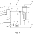
- Fig. 1 shows a schematic representation of a device 10 according to the invention for the synthesis of methanol, which comprises a synthesis reactor arrangement 1, a first reactant gas source 2 for a first reactant, a second reactant gas source 3 for a second Educt, a buffer gas source 6 for a buffer gas and a control device (not shown), wherein the first educt gas source 2, the second educt gas source 3 and the buffer gas source 6 are connected to an inlet 5 of the synthesis reactor arrangement 1.
- the first educt, the second educt and the buffer gas, if a buffer gas is introduced, are compressed via a first compressor 19.
- the first educt is carbon dioxide.
- the second educt is hydrogen, which comes from an electrolysis process using renewable energy.
- the device 10 further comprises a recycling line 7, via which an outlet 8 of the synthesis reactor arrangement 1 is connected to the inlet 5 of the synthesis reactor arrangement 1.
- the recycling line 7 comprises a heat exchanger 15, a synthesis air cooler 16, a final water cooler 17 and a separator 18.
- a synthesis loop 22 comprises the synthesis reactor arrangement 1, the recycling line 7 and a line from a mixing point 21 to the inlet 5 of the synthesis reactor arrangement 1.
- the synthesis reactor arrangement 1 produces methanol and water vapor from carbon dioxide and hydrogen.
- the condensation of the methanol formed in the synthesis reactor arrangement 1 takes place in two steps.
- the product gas mixture at the outlet of the synthesis reactor arrangement 1 is cooled via the heat exchanger 15 in countercurrent operation.
- the gas flow of the synthesis loop 22 is heated up.
- the synthesis loop flow contains the feed gas flow and the recycle gas flow.
- the product gas mixture at the outlet of the synthesis reactor arrangement 1 as well as the partially condensed methanol and the unreacted reactants are cooled to the final separation temperature in the synthesis air cooler 16 and the final water cooler 17.
- liquid methanol is separated from the gas flow.
- the methanol is discharged at a methanol outlet 12.
- a purge gas line 9 branches off from the recycle line 7.
- the recycle gas flow in the recycle line 7 is compressed to an operating pressure in a second compressor 20.
- the feed gas flow and the buffer gas flow are mixed with the recycle gas flow in the mixing point 21.
- a fresh water source 11 supplies water to a steam boiler 14. This produces water vapor 13 and hot water and/or saturated steam.
- the temperature the synthesis reactor arrangement 1 can be kept constant during the fluctuation of the feed gas flow, either by cooling the reaction heat and evaporation of water on the shell side of the synthesis reactor arrangement 1 or by heating in case of insufficient reaction waste heat by additional supply of saturated steam or hot water on the shell side from the steam boiler 14.
- the control device is designed to operate the device 10 with the following method for synthesizing methanol.
- a feed gas stream comprises carbon dioxide and hydrogen and is fed to the synthesis reactor arrangement 1, wherein methanol is produced in the synthesis reactor arrangement 1 with carbon dioxide and hydrogen, wherein in at least a first case of reducing a molar flow rate of the feed gas stream, a production rate of the methanol is temporarily reduced by reducing a proportion of the carbon dioxide in the feed gas stream.
- the proportion of carbon dioxide in the feed gas stream is reduced by adding a buffer gas made of nitrogen and hydrogen to the feed gas stream. Furthermore, in the at least one first case, the proportion of carbon dioxide in the feed gas stream is reduced by reducing an amount of carbon dioxide in the feed gas stream relative to an amount of hydrogen in the feed gas stream. The proportion of carbon dioxide in the feed gas stream is reduced such that the carbon dioxide in the feed gas stream is substoichiometric.
- the methanol from an exit stream of an outlet 8 of the synthesis reactor arrangement 1 is separated and the remaining exit stream of the synthesis reactor arrangement 1 is partially fed back as a recycle gas stream, and wherein in the at least one first case a ratio of a molar flow rate of the recycle gas stream to a molar flow rate of the feed gas stream is increased.
- the recycle ratio in the at least one first case is, for example, 20.
- the production rate of methanol is temporarily increased by the proportion of carbon dioxide in the feed gas stream is increased.
- the outlet stream of the synthesis reactor arrangement 1 is partially removed as purge gas.
- the proportion of carbon dioxide in the feed gas stream is increased by increasing an amount of carbon dioxide in the feed gas stream relative to an amount of hydrogen in the feed gas stream.
- the total pressure in the synthesis reactor arrangement 1 fluctuates by no more than 10% during the process.
Landscapes
- Chemical & Material Sciences (AREA)
- Organic Chemistry (AREA)
- Chemical Kinetics & Catalysis (AREA)
- Organic Low-Molecular-Weight Compounds And Preparation Thereof (AREA)
Abstract
Verfahren zur Synthese von Methanol, wobei ein Feedgasstrom umfassend zumindest ein erstes Edukt und ein zweites Edukt einer Synthesereaktoranordnung (1) zugeführt wird, wobei in der Synthesereaktoranordnung (1) mit dem ersten Edukt und dem zweiten Edukt Methanol erzeugt wird, wobei in zumindest einem ersten Fall einer Reduzierung einer Stoffmengenströmungsrate des Feedgasstroms eine Erzeugungsrate des Methanols zumindest zeitweise reduziert wird, indem ein Anteil des ersten Eduktes in dem Feedgasstrom reduziert wird. Ein erstes Edukt umfasst Kohlenstoffdioxid und/oder Kohlenstoffmonoxid und das zweite Edukt umfasst Wasserstoff.
Description
- Die vorliegende Erfindung betrifft ein Verfahren und eine Vorrichtung zur Synthese von Methanol, insbesondere im Wechsellastbetrieb.
- Konventionelle Anlagen zur Synthese von Methanol sind dahingehend ausgelegt, dass sie kontinuierlich bei einer konstanten Auslastung produzieren. Änderungen in der Auslastung sind im Normalbetrieb minimal. Dies wird durch die kontinuierliche Versorgung mit Feedgas ermöglicht. Lastwechsel und Prozessanpassungen zwischen definierten, stationären Zuständen erfolgen sehr langsam über Stunden bis Tage, um die Methanolanlage und den Katalysator zu schützen.
- Der planmäßige Wechsellastbetrieb des Syntheseloops mit einer Synthesereaktoranordnung ist grundsätzlich nicht vorgesehen. Insbesondere ist der Betrieb unter sehr geringer Teillast nicht üblich. Minimallasten im Produktionsbetrieb liegen typischerweise bei mindestens 50% bis 70% der Anlagenkapazität. Der Teillastfall kann für längere Zeiträume mit reduzierter Gasverfügbarkeit über mehrere Wochen oder Monate im Winter vorgesehen sein.
- Lastwechsel und Prozessanpassungen zwischen definierten stationären Zuständen erfolgen sehr langsam über Stunden bis Tage, um das Equipment und die Katalysatoren der Methanolanlage vor Beschädigung zu schützen.
- Gewöhnliches Feedgas aus Industrieprozessen enthält hauptsächlich Wasserstoff, Kohlenstoffmonoxid und Kohlenstoffdioxid.
- Die Synthese von Methanol kann grundsätzlich mit Wasserstoff durchgeführt werden, welcher von einem Elektrolyseur produziert wird. Der Elektrolyseur kann unter anderem mit erneuerbaren Energien betrieben werden. Dieser Betrieb mit erneuerbaren Energien ist vor die Herausforderung gestellt, dass die Wasserstoffproduktion mit Fluktuationen beaufschlagt ist. Die Fluktuationen der produzierten Wasserstoffmenge aus erneuerbaren Energien hängen beispielsweise von der verfügbaren Solarenergie und der verfügbaren Windenergie ab. Beispielsweise sinkt die Solarenergie in der Nacht ab oder die Windkraft sinkt während einer Sommerflaute. Typische Lastwechsel können sich hier innerhalb weniger Sekunden bis Minuten abspielen. Änderungen der Last des Elektrolyseurs sind in einer ähnlichen Größenordnung möglich. Lastwechsel bei fluktuierenden erneuerbaren Energien und des Elektrolyseurs sind jedoch um eine Größenordnung schneller als der Lastwechsel der Synthesereaktoranordnung. Des Weiteren ist der zulässige Betriebsbereich der Synthesereaktoranordnung stärker eingeschränkt als der des Elektrolyseurs und der erneuerbaren Energien. Die Synthesereaktoranordnung für die Synthese von Methanol verhält sich hierbei träge.
- Im stationären Dauerbetrieb läuft der Syntheseloop mit der Synthesereaktoranordnung unter annähernd konstanten Druck- und Temperaturbedingungen, was dementsprechend einen gleichmäßigen Betriebszustand für Apparate, Maschinen und den Katalysator der Methanolanlage bedeutet. Der Druck im Syntheseloop kann über ein Druckhalteventil konstant gehalten werden, welches Inertkomponenten und unreagierte Edukte sowie nicht abgeschiedene Produkte ablässt, sobald der Syntheseloopdruck einen bestimmten Druck übersteigt. Herausfordernd ist bei einem fluktuierenden Betrieb, also bei nicht konstanter Zufuhr der Edukte, den Betriebsdruck im Syntheseloop aufrechtzuhalten und einen hohen Umsatz der Edukte in der Synthesereaktoranordnung zu ermöglichen.
- Eine Möglichkeit den Umsatz der Edukte zu erhöhen ist es, unreagierte Edukte wieder im Syntheseloop rezirkulieren zu lassen (Recycle). Zudem kann durch den Recycle erreicht werden, dass sich in den Eduktgasströmen enthaltenes Inertgas im Syntheseloop akkumuliert und den Druck des Syntheseloops stabilisiert. Bei geringen Inertgasanteilen in den Eduktgasströmen kann diese Stabilisierung des Druckes zu langsam sein, um den Fluktuationen eines zweiten Eduktstromes zu folgen und somit nicht oder nur unzureichend nutzbar sein. Auch ist dieser Effekt nicht nutzbar, wenn der Anteil an Inerten in den Edukstömen sehr gering oder gar Null ist.
- Bei einem Wechsel von Volllast im Normalbetrieb in den Teillastbetrieb (Verringerung der Eduktgasströme) sinkt ohne zusätzliche Maßnahmen wie z.B. Veränderung des Recycle-Mengenstromes der Druck im Syntheseloop. Ursächlich ist hier, dass der Syntheseloop zunächst noch eduktreiches rezirkuliertes Recyclegas enthält, welches im Reaktor reagiert und Methanol bildet. Das Methanol wird im Abscheider abgeschieden. Dies führt dazu, dass die Gasphase im Syntheseloop an Stoffmenge verliert. Der Partialdruck der gasförmigen Edukte sinkt ab. Der Druck des konstanten Volumens des Syntheseloops sinkt folglich auch ab. Das Druckhalteventil kann den Druckabfall nicht verhindern, da dies nur einen erhöhten Druck durch Öffnung des Ventils ablassen kann.
- Sinkt der Feedgasstrom durch Fluktuationen bedingt durch beispielsweise einen Elektrolyseur, welcher mit erneuerbaren Energien betrieben wird, rapide innerhalb von Sekunden bis Minuten ab, kann der Druck im Methanolreaktor nicht schnell genug stabilisiert werden. Ein rapider Anstieg des Feedgasstroms kann hingegen über das Druckhalteventil stabilisiert werden, um einen Betriebsdruck für eine Teillast oder Volllast nicht zu überschreiten.
- Hiervon ausgehend liegt der vorliegenden Erfindung die Aufgabe zugrunde, einen Wechsellastbetrieb in der Synthese von Methanol zu ermöglichen.
- Diese Aufgabe wird gelöst mit dem Verfahren und der Vorrichtung gemäß den unabhängigen Ansprüchen. Weitere vorteilhafte Ausgestaltungen der Erfindung sind in den abhängig formulierten Ansprüchen angegeben. Die in den abhängig formulierten Ansprüchen einzeln aufgeführten Merkmale sind in technologisch sinnvoller Weise miteinander kombinierbar und können weitere Ausgestaltungen der Erfindung definieren. Darüber hinaus werden die in den Ansprüchen angegebenen Merkmale in der Beschreibung näher präzisiert und erläutert, wobei weitere bevorzugte Ausgestaltungen der Erfindung dargestellt werden.
- Erfindungsgemäß wird ein Verfahren zur Synthese von Methanol vorgestellt, wobei ein Feedgasstrom zumindest ein erstes Edukt und ein zweites Edukt umfasst, welches einer Synthesereaktoranordnung zugeführt wird. In der Synthesereaktoranordnung wird mit dem ersten Edukt und dem zweiten Edukt Methanol erzeugt. In zumindest einem ersten Fall einer Reduzierung einer Stoffmengenströmungsrate des Feedgasstroms wird eine Erzeugungsrate des Methanols zumindest zeitweise reduziert, indem ein Anteil des ersten Eduktes in dem Feedgasstrom reduziert wird.
- Das erste Edukt und das zweite Edukt können zu einem Feedgasstrom gemischt werden. Der Feedgasstrom wird der Synthesereaktoranordnung zugeführt. In der Synthesereaktoranordnung können das erste Edukt und das zweite Edukt zu Methanol als einem Produkt und optional zu einem oder mehreren Nebenprodukten reagieren.
- In der Synthesereaktoranordnung sind das erste Edukt und das zweite Edukt vorzugsweise gasförmig.
- Die Synthesereaktoranordnung kann aus einem Reaktorsystem geeigneter Reaktoren bestehen. Die Synthesereaktoranordnung umfasst vorzugsweise einen Reaktor, bevorzugt mehrere parallel oder in Serie geschaltete Reaktoren. Die Synthesereaktoranordnung kann insbesondere durch einen wassergekühlten und/oder gasgekühlten Reaktor gebildet sein.
- Der in der Gasphase in der Synthesereaktoranordnung befindliche Stoffmengenstrom kann aufgrund der Stöchiometrie der Methanolbildungsreaktion abnehmen. Das heißt die "Anzahl" der Moleküle in der Gasphase nimmt durch die Reaktion ab, wodurch der Druck sinkt. Durch einen verringerten Stoffmengenstrom in der Gasphase kann der Druck im Syntheseloop absinken, sofern nicht mit dem in den Syntheseloop eintretenden Feedgas die aus der Gasphase verlorene Stoffmenge wieder zugeführt wird.
- Der Stoffmengenstrom kann beispielsweise in kmol pro Zeiteinheit angegeben werden.
- Aufgrund der Stöchiometrie der Methanolbildungsreaktion ist das erste Edukt im Feedgas zum Syntheseloop vorzugsweise in einem niedrigeren Anteil vorhanden als das zweite Edukt. Bevorzugt ist ein Verhältnis vom ersten Edukt zum zweiten Edukt im Bereich von eins zu drei mit einer Varianz von 5% oder von eins zu zwei mit einer Varianz von 5%. Der Begriff Anteil meint hier den Stoffmengenanteil in mol% des Feedgasstroms. Ein Verhältnis von eins zu drei mit einer Varianz von 5% ist insbesondere bei Kohlendioxid und Wasserstoff bevorzugt. Ein Verhältnis von eins zu zwei mit einer Varianz von 5% ist insbesondere bei Kohlenmonoxid und Wasserstoff bevorzugt.
- Der Syntheseloop umfasst vorzugsweise die Synthesereaktoranordnung und alle Leitungen, die den Auslass der Synthesereaktoranordnung mit dem Einlass der Synthesereaktoranordnung verbinden.
- Der Druck im Syntheseloop kann im Wesentlichen durch die Stoffmenge in der Gasphase, die Temperatur und das Syntheseloopvolumen bestimmt werden. Die Verringerung des Stoffmengenstroms in der Gasphase kann durch Reaktion des ersten Edukts und des zweiten Edukts zum Methanol in der Synthesereaktoranordnung und die Kondensation und Abscheidung des Methanols bedingt werden. Der Druckabfall des Syntheseloops kann umso höher sein, je mehr Produkt gebildet wird und abgeschieden wird, sofern nicht mit dem Feedgas die aus der Gasphase verlorene Stoffmenge wieder zugeführt wird.
- Das erste Edukt weist vorzugsweise eine höhere Löslichkeit als das zweite Edukt in einem Methanol-Wasser-Gemisch auf, sodass der Anteil des ersten Edukts in der Gasphase durch eine Löslichkeit in diesem Methanol-Wasser-Gemisch noch weiter reduziert werden kann.
- Die Kondensation des in der Synthesereaktoranordnung gebildeten Methanols kann in zwei Schritten erfolgen. Im ersten Schritt wird das Produktgasgemisch am Auslass der Synthesereaktoranordnung über einen Wärmeübertrager im Gegenstrombetrieb gekühlt. Gleichzeitig wird der Gasstrom am Einlass der Synthesereaktoranordnung über den Wärmeübertrager aufgewärmt. Im zweiten Schritt wird in einem oder mehreren luft- oder wassergekühlten Wärmeübertragern das Produktgasgemisch am Auslass der Synthesereaktoranordnung, inklusive teilkondensierten Methanols und unreagierter Edukte, auf die finale Temperatur des Abscheiders gekühlt, wobei weiteres Methanol kondensiert.
- Die Reaktionsrate von dem ersten Edukt und dem zweiten Edukt zu Methanol kann in der Synthesereaktoranordnung bei konstanter Temperatur und konstanter Katalysatormenge durch die Partialdrücke des ersten Edukts und des zweiten Edukts bestimmt werden. Weiterhin kann aufgrund der Gleichgewichtsreaktion die Reaktionsrate auch durch den Partialdruck des Methanols und den Partialdruck eines oder mehrerer Nebenprodukte bestimmt werden.
- Ein Wechsellastbetrieb bezeichnet den Betrieb der Synthesereaktoranordnung mit wechselnder Last, d.h. wechselndem Reaktoreintrittsgasstrom, insbesondere infolge eines wechselnden Eduktstroms der dem Syntheseloop zugeführt wird. Der sogenannte Lastbereich für den Eduktstrom der dem Syntheseloop zugeführt wird liegt vorzugsweise zu jedem Zeitpunkt des Verfahrens zwischen 0% und 100% der Anlagenkapazität, bevorzugt zwischen 20% und 100% der Anlagenkapazität. Eine Last von 100% wird auch als Volllast bezeichnet. Ein Lastbereich unter 100% wird auch als Teillast bezeichnet.
- In zumindest einem ersten Fall wird die Stoffmengenströmungsrate des Feedgasstroms reduziert. Bei einem Lastwechsel von einem höheren Lastbereich in einen niedrigeren Lastbereich kann die Stoffmengenströmungsrate des Feedgasstroms abnehmen. Hierfür nimmt der Stoffmengenstrom des ersten Edukts und/oder der Stoffmengenstrom des zweiten Edukts ab.
- Aufgrund der Trägheit der im Syntheseloop befindlichen Gasmenge und Zusammensetzung setzt die Synthesereaktoranordnung die Edukte zunächst weiterhin wie im höheren Lastbereich um. Mit der reduzierten Stoffmengenströmungsrate kann jedoch ein Defizit des ersten Edukts und/oder des zweiten Edukts entstehen und damit ein Druckabfall der Partialdrücke des ersten Edukts und/oder des zweiten Edukts.
- Indem der Anteil des ersten Eduktes in dem Feedgasstrom reduziert wird, wird die Erzeugungsrate des Methanols zumindest zeitweise reduziert. Dies hat den Vorteil, dass der Partialdruck des ersten Edukts reduziert wird, wodurch die Reaktion gehemmt wird und die Erzeugungsrate von Methanol absinkt. Dies hat den weiteren Vorteil, dass die Stoffmenge in der Gasphase stabilisiert wird und der Druck im Syntheseloop nicht oder zumindest nur geringfügig abfällt. Da die Erzeugungsrate von Methanol reduziert wird, wird weniger vom ersten Edukt und weniger vom zweiten Edukt umgesetzt. Somit wird aufgrund der reduzierten Edukt-Stoffmengenströmungsrate pro Zeiteinheit weniger Methanol gebildet, wodurch der Druck in der Synthesereaktoranordnung aufgrund der Stöchiometrie der Methanolbildungsreaktion weniger stark abfällt. Das Defizit an erstem oder zweitem Edukt trägt dadurch zur Stabilisierung des Drucks in der Synthesereaktoranordnung bei.
- Das erste Edukt macht vorzugsweise bei stöchiometrischem Verhältnis der Edukte stoffmengenmäßig einen geringeren Anteil im Feedgasstrom in den Syntheseloop und in die Synthesereaktoranordnung aus, im Vergleich zum zweiten Edukt. Eine Hemmung der Reaktion kann daher vergleichsweise einfach mit einer Verringerung des Anteils des ersten Eduktes erreicht werden. Dies hat den Vorteil, dass eine Verringerung des Stoffmengenanteils in Bezug auf die gesamte Stoffmenge an Edukten minimiert werden kann, was einen geringen Partialdruckabfall nach sich zieht und damit einen geringeren Einfluss auf den Gesamtdruckabfall ausübt.
- Das beschriebene Verfahren ist vor allem dazu geeignet, auf vergleichsweise schnelle Schwankungen im Feedgasstrom zu reagieren. Auf langsamere Schwankungen kann auch auf andere Weise reagiert werden. Um gegenüber einem herkömmlichen Verfahren einen Vorteil zu erzielen, genügt es daher, dass in zumindest einem ersten Fall einer Reduzierung einer Stoffmengenströmungsrate des Feedgasstroms die Erzeugungsrate des Methanols zumindest zeitweise reduziert wird, indem ein Anteil des ersten Eduktes in dem Feedgasstrom reduziert wird. Dabei kann die Veränderung der Zufuhr am ersten Edukt auch schon durchgeführt werden, bevor ein Lastwechsel initiiert wird, d.h. bevor die Zufuhr an einem zweiten Edukt (H2 aus Elektrolyse) sich ändert. Auf das Verhältnis der Edukte im Feedgasstrom bei einer Vergrößerung der Stoffmengenströmungsrate des Feedgasstroms kommt es im Allgemeinen nicht an, um den Druck im Syntheseloop zu kontrollieren. Auch ist das Verhältnis der Edukte im Feedgasstrom bei konstantem Feedgasstrom unbeachtlich. Es genügt bereits, dass in zumindest einem ersten Fall einer (erwarteten) Reduzierung einer Stoffmengenströmungsrate des Feedgasstroms eine Erzeugungsrate des Methanols zumindest zeitweise reduziert wird, um die Auswirkungen der Verringerung der Stoffmengenströmungsrate des Feedgasstroms kurzfristig auszugleichen. Das liegt daran, dass der Druck in dem Rohrleitungssystem neben der Beeinflussung des Verhältnisses der Edukte im Feedgasstrom auch auf andere Arten beeinflusst werden kann. Hierzu kommen insbesondere alle Möglichkeiten in Betracht, welche auch bei einer herkömmlichen Anordnung zur Synthese von Methanol eingesetzt werden. Beispielsweise kann ein zu großer Druck über ein Überdruckventil abgelassen werden, welches vergleichsweise schnell reagieren kann. Die Gefahr eines zu großen Drucks unterscheidet sich also qualitativ von der Gefahr eines zu geringen Drucks.
- Auch ist es nicht erforderlich, dass der Anteil des ersten Eduktes in dem Feedgasstrom jedes Mal reduziert wird, wenn sich die Stoffmengenströmungsrate des Feedgasstroms verringert. Es genügt, dass der Anteil des ersten Eduktes in dem Feedgasstrom zumindest in einem ersten Falle einer Verringerung der Stoffmengenströmungsrate des Feedgasstroms verringert wird, also mindestens einmal bei der Durchführung des Verfahrens. Insbesondere im Falle einer langsamen Verringerung der Stoffmengenströmungsrate des Feedgasstroms mag es nicht erforderlich sein, mit einer Verringerung des Anteils des ersten Edukts in dem Feedgasstrom zu reagieren. Es ist jedoch bevorzugt, dass der Anteil des ersten Eduktes in dem Feedgasstrom jedes Mal reduziert wird, wenn sich die Stoffmengenströmungsrate des Feedgasstroms schneller als ein Druckveränderungs-Grenzwert verringert und/oder jedes Mal reduziert wird, wenn sich die Stoffmengenströmungsrate des Feedgasstroms auf einen Wert unterhalb eines Druck-Grenzwert verringert.
- In einer bevorzugten Ausführungsform wird in dem zumindest einen ersten Fall der Anteil des ersten Eduktes in dem Feedgasstrom reduziert, indem ein Puffergas zum Feedgasstrom hinzugefügt wird.
- Die Reaktionsrate der Edukte zu Methanol kann reduziert werden, indem der Partialdruck der Edukte reduziert wird. Die Wahrscheinlichkeit für die Reaktion vom ersten Edukt und zweiten Edukt zu Methanol nimmt mit niedrigerem Partialdruck ab. Hinzufügen von einem Puffergas zum Feedgasstrom bei einem definierten Gesamtdruck reduziert den Anteil der Edukte im Feedgasstrom und somit deren Partialdruck.
- Eine Reduzierung der Erzeugungsrate ist von Vorteil, da das erste Edukt und das zweite Edukt zu Methanol reagieren und die reagierte Stoffmenge der Gasphase des Syntheseloops entzogen wird und so einen Druckabfall begünstigt. Wenn nun weniger Methanol produziert wird, wird dementsprechend weniger Edukt verbraucht.
- Diese Ausführungsform dient vorzugsweise dazu, den Partialdruck des ersten Edukts und des zweiten Edukts zu reduzieren, die Reaktion zu hemmen und weniger Methanol herzustellen. Ein weiterer Vorteil dieser Ausführungsform ist, dass das Puffergas einen Druckabfall stabilisieren kann, indem das Puffergas zur Druckhaltung im Syntheseloop fehlende Stoffmenge der Gasphase auffüllen kann und der Gesamtdruck im Syntheseloop stabilisiert wird.
- In einer weiteren bevorzugten Ausführungsform wird in dem zumindest einen ersten Fall der Anteil des ersten Eduktes in dem Feedgasstrom reduziert, indem eine Menge des ersten Edukts in dem Feedgasstrom relativ zu einer Menge des zweiten Edukts in dem Feedgasstrom reduziert wird.
- Dies kann vorzugsweise erreicht werden, indem das zweite Edukt überstöchiometrisch dem Feedgasstrom hinzugefügt wird.
- Vorzugsweise fluktuiert die Menge des zweiten Edukts. Eine Fluktuation meint die Änderung des Stoffmengenstroms und/oder des Partialdrucks des zweiten Edukts über die Zeit.
- Diese Ausführungsform dient vorzugsweise dazu, die Erzeugungsrate des Methanols zu reduzieren, indem der Partialdruck des ersten Edukts so weit reduziert wird, dass die Reaktion gehemmt wird.
- In einer ersten Möglichkeit kann die Stoffmengenströmungsrate des zweiten Eduktes erhöht werden. So kann die Reaktion durch eine Verknappung an erstem Edukt gehemmt werden, und der Überschuss an zweitem Edukt gleicht die Verknappung der Stoffmenge an einem ersten Edukt aus. Der Druck im Syntheseloop kann so stabilisiert werden. Nachteil dieser Möglichkeit ist, dass das zweite Edukt nicht ohne weiteres zur Verfügung steht. Denn in dem zumindest einen ersten Fall kann der Feedgasstrom insbesondere dann reduziert werden, wenn das zweite Edukt zeitweise weniger zur Verfügung steht.
- In einer zweiten Möglichkeit wird die Stoffmengenströmungsrate des ersten Eduktes reduziert, bevor das zweite Edukt durch Fluktuation absinkt. Dies hat den Effekt, dass das zweite Edukt überstöchiometrisch im Feedgasstrom vorliegt. Durch Verringerung der Menge des ersten Edukts reagiert das immer weniger werdende erste Edukt mit dem zweiten Edukt zu Methanol, wodurch der Anteil des ersten Edukts im Syntheseloop sinkt. Hierdurch sinkt der Partialdruck des ersten Edukts ab und die Reaktion wird gehemmt. Zugleich reichert sich der Gehalt an einem zweiten Edukt im Syntheseloop an. Steht nun durch die eintretende Fluktuation weniger zweites Edukt zur Verfügung, dann kann der Feedgasstrom reduziert werden und der Druck im Syntheseloop ist aufgrund der gehemmten Reaktion stabil.
- Vorzugsweise kann der Anteil des ersten Eduktes in dem Feedgasstrom in dem zumindest einen ersten Fall so weit reduziert werden, dass das erste Edukt im Syntheseloop unterstöchiometrisch vorliegt.
- Den vorhergehenden Ausführungsformen ist gemein, dass in zumindest einem ersten Fall einer Reduzierung einer Stoffmengenströmungsrate des Feedgasstroms eine Erzeugungsrate des Methanols reduziert wird, indem der Anteil des ersten Edukts die Reaktion zu Methanol durch einen niedrigen Partialdruck hemmt.
- In einer weiteren bevorzugten Ausführungsform wird Methanol aus einem Austrittsstrom der Synthesereaktoranordnung abgeschieden und der verbleibende Austrittsstrom der Synthesereaktoranordnung als ein Recyclegasstrom zumindest teilweise erneut zugeführt, wobei in dem zumindest einen ersten Fall ein Verhältnis einer Stoffmengenströmungsrate des Recyclegasstroms zu einer Stoffmengenströmungsrate des Feedgasstroms erhöht wird.
- Das Verhältnis der Stoffmengenströmungsrate des Recyclegasstroms zu der Stoffmengenströmungsrate des Feedgasstroms wird auch Recycleverhältnis genannt.
- Vorzugsweise ist in dem zumindest einen ersten Fall ein Recycleverhältnis von 2 bis 200 vorhanden. Bevorzugt ist ein Recycleverhältnis von 3 bis 30.
- Vorzugsweise weisen der gemischte Feedgasstrom und Recyclegasstrom am Einlass der Synthesereaktoranordnung ein Stoffmengenverhältnis vom ersten Edukt zum zweiten Edukt im Bereich von 0,001 bis 0,33auf, bevorzugt im Bereich von 0,005 bis 0,33.
- Eine signifikante Erhöhung des Recycleverhältnisses und somit verstärkte Anreicherung nichtreagierter Komponenten ist im Allgemeinen nur im Teillastbereich möglich, da das maximale Recycleverhältnis durch die Obergrenze eines förderbaren Recyclegasstroms limitiert ist.
- Diese Ausführungsform dient vorzugsweise dazu, den Umsatz der Edukte zu erhöhen und Inertgase sowie unreagierte Edukte als Puffer zu akkumulieren.
- Das erste Edukt und das zweite Edukt können im Einlass der Synthesereaktoranordnung und/oder vor dem Einlass der Synthesereaktoranordnung gemischt werden. Weitere Ströme wie der Recyclegasstrom und das Puffergas können dem Feedgasstrom im Einlass und/oder vor dem Einlass der Synthesereaktoranordnung beigemischt werden.
- In zumindest einem zweiten Fall wird die Stoffmengenströmungsrate des Feedgasstroms vorzugsweise erhöht. Analog zum zumindest einen ersten Fall ist es nicht erforderlich, dass der Anteil des ersten Eduktes in dem Feedgasstrom jedes Mal erhöht wird, wenn sich die Stoffmengenströmungsrate des Feedgasstroms vergrößert. Es genügt, dass der Anteil des ersten Eduktes in dem Feedgasstrom in zumindest einem zweiten Falle einer Vergrößerung der Stoffmengenströmungsrate des Feedgasstroms vergrößert wird, also mindestens einmal bei der Durchführung des Verfahrens.
- In einer weiteren bevorzugten Ausführungsform wird in zumindest einem zweiten Fall einer Erhöhung einer Stoffmengenströmungsrate des Feedgasstroms eine Erzeugungsrate des Methanols zumindest zeitweise erhöht, indem der Anteil des ersten Eduktes in dem Feedgasstrom erhöht wird.
- Vorzugsweise wird ein etwaiger Druckanstieg im Syntheseloop durch die Erhöhung der Stoffmengenströmungsrate über eine Spülgasleitung abgelassen. Besonders bevorzugt wird der Austrittsstrom der Synthesereaktoranordnung als Spülgas zumindest teilweise entfernt. Dadurch kann das zweite Edukt, welches überstöchiometrisch im Syntheseloop vorhanden ist und/oder das Puffergas aus dem Syntheseloop entfernt werden. Der Partialdruck des ersten Edukts wird mit neu in den Loop eingespeister Menge an erstem Edukt erhöht und hemmt nicht mehr die Reaktion. Die erhöhte Stoffmengenströmungsrate des Feedgasstroms erhöht dann entsprechend die Erzeugungsrate des Methanols.
- Diese Ausführungsform dient vorzugsweise dazu, die Erzeugungsrate des Methanols in dem zumindest einen zweiten Fall zügig zu erhöhen und den Gesamtdruck in der Synthesereaktoranordnung nicht ansteigen zu lassen.
- In einer weiteren bevorzugten Ausführungsform wird in dem zumindest einen zweiten Fall der Anteil des ersten Eduktes in dem Feedgasstrom erhöht, indem eine Menge des ersten Edukts in dem Feedgasstrom relativ zu einer Menge des zweiten Edukts in dem Feedgasstrom erhöht wird.
- Durch den ersten Fall einer Reduzierung der Stoffmengenströmungsrate kann das zweite Edukt überstöchiometrisch im Syntheseloop vorhanden sein.
- Wenn der Feedgasstrom rapide zunimmt, kann die Erzeugungsrate des Methanols zunächst zu niedrig sein. Die Folge kann ein steigender Druck im Syntheseloop sein. Um die Erzeugungsrate des Methanols wieder zu erhöhen, wird der Anteil des ersten Eduktes im Feedgasstrom zumindest zeitweise erhöht. Der Partialdruck des ersten Edukts steigt und hemmt nicht mehr die Erzeugungsrate des Methanols. Dieser erhöhte Anteil des ersten Edukts kann mit dem überstöchiometrisch vorhandenen zweiten Edukt reagieren und die Erzeugungsrate des Methanols erhöhen, sodass das erste Edukt und das zweite Edukt zu Methanol reagieren. Dies hat den Effekt, dass der überschüssige Stoffmengenstrom durch den erhöhten Feedgasstrom durch die Reaktion von ersten Edukt und zweiten Edukt zu Methanol abgebaut wird.
- Diese Ausführungsform dient vorzugsweise dazu, die Erzeugungsrate des Methanols in dem zumindest einen zweiten Fall zu erhöhen und den Gesamtdruck im Syntheseloop nicht ansteigen zu lassen.
- Vorzugsweise ist das erste Edukt Kohlenstoffdioxid oder Kohlenstoffmonoxid.
- Vorzugsweise ist das zweite Edukt Wasserstoff.
- Besonders bevorzugt stammt das zweite Edukt aus einer Wasserelektrolyse mit erneuerbarer Energie.
- Der Feedgasstrom umfasst vorzugsweise 0 mol% bis 35 mol% Kohlenstoffdioxid und 65 mol% bis 100 mol% Wasserstoff. Bevorzugt umfasst der Feedgasstrom 15 mol% bis 30 mol% Kohlenstoffdioxid und 70 mol% bis 85 mol% Wasserstoff.
- In einer weiteren bevorzugten Ausführungsform enthält das Puffergas ein Inertgas oder mehrere Inertgase und/oder Methan und/oder Wasserstoff.
- Das Inertgas ist vorzugsweise Argon. Das Inertgas ist besonders bevorzugt Stickstoff. Es können auch mehre Inertgase gemischt werden. Das Inertgas beinhaltet vorzugsweise ein Gemisch aus Argon und/oder Stickstoff.
- In einer weiteren bevorzugten Ausführungsform fluktuiert ein Gesamtdruck in der Synthesereaktoranordnung während der Durchführung des Verfahrens um nicht mehr als 40 %, bevorzugt nicht mehr als 20 %, bevorzugt nicht mehr als 10%.
- Ein erwünschter Gesamtdruck ist ein vom Lastbereich unabhängiger Betriebsdruck der Synthesereaktoranordnung. Hohe Druckschwankungen erhöhen die Anforderungen an die verwendeten Rohrleitungen und Apparate, da diese für Druckschwankungen ausgelegt sein müssen.
- Das beschriebene Verfahren ist besonders dann sinnvoll, wenn die Synthese von Methanol im Wechsellastbetrieb ermöglicht werden soll, vor allem wenn der Feedgasstrom reduziert werden soll. Dieser Fall kann eintreten, wenn das zweite Edukt fluktuiert. Statt den reduzierten Edukt-Stoffmengenstrom durch ein Puffergas vollständig aufzufüllen, um einen Druckabfall zu verhindern, kann durch Reduzierung des ersten Edukts-Stoffmengenstroms die Reaktion zu Methanol gehemmt werden. Besonders vorteilhaft ist es, den ersten Edukt-Stoffmengenstrom zu reduzieren, bevor der zweite Edukt-Stoffmengenstrom durch Fluktuation reduziert wird.
- Als ein weiterer Aspekt der Erfindung wird eine Vorrichtung zur Synthese von Methanol vorgestellt, welche eine Synthesereaktoranordnung, eine erste Eduktgasquelle für ein erstes Edukt, eine zweite Eduktgasquelle für ein zweites Edukt und eine Steuereinrichtung umfasst, wobei die erste Eduktgasquelle und die zweite Eduktgasquelle mit einem Einlass der Synthesereaktoranordnung verbunden sind, und wobei die Steuereinrichtung dazu eingerichtet ist, die Vorrichtung mit dem beschriebenen Verfahren zu betreiben.
- Die erste Eduktgasquelle kann vorzugsweise ein Kohlenstoffdioxid-Abscheideprozess oder eine Kohlenstoffdioxidleitung sein. Das erste Edukt ist vorzugsweise Kohlenstoffdioxid und/oder Kohlenstoffmonoxid.
- Die zweite Eduktgasquelle ist vorzugsweise ein Wasserelektrolyseprozess. Der Wasserelektrolyseprozess wird vorzugsweise mit einer Versorgung von erneuerbarer Energie betrieben, welche fluktuieren kann. Das zweite Edukt ist vorzugsweise Wasserstoff.
- Für die Steuereinrichtung wird vorzugsweise die Gaszusammensetzung, der Stoffmengenstrom und der Druck an verschiedenen Stellen gemessen. Insbesondere im Feedgasstrom wird vorzugsweise untersucht, welcher Anteil des ersten Edukts, des zweiten Edukts und etwaiger Restkomponenten wie beispielsweise Inertgase vor Eintritt in den Syntheseloop vorliegen. Weitere Messstellen können am Einlass der Synthesereaktoranordnung oder am Auslass der Synthesereaktoranordnung vorgesehen sein. Falls ein Recyclegasstrom vorhanden ist, kann in der Recycleleitung die Gaszusammensetzung, der Mengenstrom und der Druck gemessen werden.
- In einer weiteren bevorzugten Ausführungsform weist die Vorrichtung weiterhin eine Puffergasquelle für ein Puffergas auf, wobei die Puffergasquelle mit einem Einlass der Synthesereaktoranordnung verbunden ist.
- Diese Ausführungsform dient vorzugsweise dazu, in dem zumindest einen ersten Fall den Anteil des ersten Eduktes in dem Feedgasstrom zu reduzieren, indem ein Puffergas zum Feedgasstrom hinzugefügt wird.
- In einer weiteren bevorzugten Ausführungsform umfasst die Vorrichtung weiterhin eine Recycleleitung, über welche ein Auslass der Synthesereaktoranordnung mit einem Einlass der Synthesereaktoranordnung verbunden ist.
- In dieser bevorzugten Ausführungsform kann der Umsatz der Edukte zu Methanol erhöht werden und Inertgase sowie unreagierte Edukte als Puffer akkumuliert werden.
- In einer weiteren bevorzugten Ausführungsform umfasst die Vorrichtung weiterhin eine Spülgasleitung, welche von der Recycleleitung abzweigt.
- In dieser bevorzugten Ausführungsform kann ein erhöhter Druck im Syntheseloop als Reaktion auf einen spontan angestiegenen Feedgasstrom kontrolliert in einem definierten Bereich gehalten bzw. gesenkt werden.
- Die Verwendung einer wie beschrieben ausgestalteten Vorrichtung hat den Vorteil, dass ein Wechsellastbetrieb in der Synthese von Methanol ermöglicht wird. Der Wechsellastbetrieb kann durch eine Reduzierung und Erhöhung des Feedgasstroms eintreten und auf einem fluktuierenden zweiten Edukt basieren. Durch eine Reduzierung und Erhöhung des Anteils des ersten Edukts im Feedgasstrom kann die Reaktionsrate gesteuert werden und dadurch kann der Gesamtdruck im Syntheseloop kontrolliert werden.
- Die Erfindung wird nachfolgend anhand der Figur näher erläutert. Die Figur zeigt ein besonders bevorzugtes Ausführungsbeispiel, auf welches die Erfindung jedoch nicht begrenzt ist. Die Figur und die darin dargestellten Größenverhältnisse sind nur schematisch. Es zeigen:
- Fig. 1:
- eine schematische Darstellung einer erfindungsgemäßen Vorrichtung zur Synthese von Methanol.
-
Fig. 1 zeigt eine schematische Darstellung einer erfindungsgemäßen Vorrichtung 10 zur Synthese von Methanol, welche eine Synthesereaktoranordnung 1, eine erste Eduktgasquelle 2 für ein erstes Edukt, eine zweite Eduktgasquelle 3 für ein zweites Edukt, eine Puffergasquelle 6 für ein Puffergas und eine nicht gezeigte Steuereinrichtung umfasst, wobei die erste Eduktgasquelle 2, die zweite Eduktgasquelle 3 und die Puffergasquelle 6 mit einem Einlass 5 der Synthesereaktoranordnung 1 verbunden sind. Das erste Edukt, das zweite Edukt und das Puffergas, sofern ein Puffergas eingebracht wird, werden über einen ersten Verdichter 19 verdichtet. Das erste Edukt ist Kohlenstoffdioxid. Das zweite Edukt ist Wasserstoff, welches aus einem Elektrolyseprozess mit erneuerbarer Energie stammt. - Die Vorrichtung 10 umfasst weiterhin eine Recycleleitung 7, über welche ein Auslass 8 der Synthesereaktoranordnung 1 mit dem Einlass 5 der Synthesereaktoranordnung 1 verbunden ist. Die Recyclingleitung 7 umfasst einen Wärmeübertrager 15, einen Syntheseluftkühler 16, einen finalen Wasserkühler 17 und einen Abscheider 18. Ein Syntheseloop 22 umfasst die Synthesereaktoranordnung 1, die Recycleleitung 7 sowie eine Leitung von einer Mischstelle 21 bis zum Einlass 5 der Synthesereaktoranordnung 1.
- Die Synthesereaktoranordnung 1 produziert Methanol und Wasserdampf aus Kohlenstoffdioxid und Wasserstoff. Die Kondensation des in der Synthesereaktoranordnung 1 gebildeten Methanols erfolgt in zwei Schritten. Im ersten Schritt wird das Produktgasgemisch am Auslass der Synthesereaktoranordnung 1 über den Wärmeübertrager 15 im Gegenstrombetrieb gekühlt. Gleichzeitig wird der Gasstrom des Syntheseloops 22 aufgewärmt. Der Syntheseloopstrom enthält den Feedgasstrom und den Recyclegasstrom. Im zweiten Schritt wird im Syntheseluftkühler 16 und im finalen Wasserkühler 17 das Produktgasgemisch am Auslass der Synthesereaktoranordnung 1 sowie das teilkondensierte Methanol und die unreagierten Edukte auf die finale Abscheidetemperatur gekühlt. Im Abscheider 18 wird flüssiges Methanol vom Gasstrom getrennt. Das Methanol wird an einem Methanolauslass 12 ausgegeben.
- Eine Spülgasleitung 9 zweigt von der Recycleleitung 7 ab. Der Recyclegasstrom in der Recycleleitung 7 wird in einem zweiten Verdichter 20 auf einen Betriebsdruck verdichtet. Der Feedgasstrom und der Puffergasstrom werden in der Mischstelle 21 mit dem Recyclegasstrom vermischt.
- Eine Frischwasserquelle 11 liefert Wasser an einen Dampfkessel 14. Dieser produziert Wasserdampf 13 und heißes Wasser und/oder gesättigten Dampf. Die Temperatur der Synthesereaktoranordnung 1 kann während der Fluktuation des Feedgasstroms konstant gehalten werden, entweder durch Kühlung der Reaktionswärme und Verdampfung von Wasser auf der Mantelseite der Synthesereaktoranordnung 1 oder durch Erwärmung bei unzureichender Reaktionsabwärme durch zusätzliche Zufuhr von gesättigtem Dampf oder heißem Wasser auf der Mantelseite aus dem Dampfkessel 14.
- Die Steuereinrichtung ist dazu eingerichtet, die Vorrichtung 10 mit dem folgenden Verfahren zur Synthese von Methanol zu betreiben.
- Ein Feedgasstrom umfasst Kohlenstoffdioxid und Wasserstoff und wird der Synthesereaktoranordnung 1 zugeführt, wobei in der Synthesereaktoranordnung 1 mit Kohlenstoffdioxid und Wasserstoff Methanol erzeugt wird, wobei in zumindest einem ersten Fall einer Reduzierung einer Stoffmengenströmungsrate des Feedgasstroms eine Erzeugungsrate des Methanols zeitweise reduziert wird, indem ein Anteil des Kohlenstoffdioxids in dem Feedgasstrom reduziert wird.
- In dem zumindest einen ersten Fall wird der Anteil des Kohlenstoffdioxids in dem Feedgasstrom reduziert, indem ein Puffergas aus Stickstoff und Wasserstoff zum Feedgasstrom hinzugefügt wird. Weiterhin wird in dem zumindest einen ersten Fall der Anteil des Kohlenstoffdioxids in dem Feedgasstrom reduziert, indem eine Menge des Kohlenstoffdioxids in dem Feedgasstrom relativ zu einer Menge des Wasserstoffs in dem Feedgasstrom reduziert wird. Dabei wird der Anteil des Kohlenstoffdioxids in dem Feedgasstrom so reduziert, dass das Kohlenstoffdioxid in dem Feedgasstrom unterstöchiometrisch vorliegt.
- Das Methanol aus einem Austrittsstrom eines Auslasses 8 der Synthesereaktoranordnung 1 wird abgeschieden und der verbleibende Austrittsstrom der Synthesereaktoranordnung 1 als ein Recyclegasstrom teilweise erneut zugeführt, und wobei in dem zumindest einen ersten Fall ein Verhältnis einer Stoffmengenströmungsrate des Recyclegasstroms zu einer Stoffmengenströmungsrate des Feedgasstroms erhöht wird. Das Recycleverhältnis beträgt in dem zumindest einen ersten Fall beispielsweise 20.
- In zumindest einem zweiten Fall einer Erhöhung einer Stoffmengenströmungsrate des Feedgasstroms wird die Erzeugungsrate des Methanols zeitweise erhöht, indem der Anteil des Kohlenstoffdioxids in dem Feedgasstrom erhöht wird. Hierfür wird der Austrittsstrom der Synthesereaktoranordnung 1 als Spülgas teilweise entfernt.
- Der Anteil des Kohlenstoffdioxids in dem Feedgasstrom wird erhöht, indem eine Menge des Kohlenstoffdioxids in dem Feedgasstrom relativ zu einer Menge des Wasserstoffs in dem Feedgasstrom erhöht wird.
- Der Gesamtdruck in der Synthesereaktoranordnung 1 fluktuiert während der Durchführung des Verfahrens um nicht mehr als 10 %.
-
- 1
- Synthesereaktoranordnung
- 2
- erste Eduktgasquelle
- 3
- zweite Eduktgasquelle
- 5
- Einlass des Synthesereaktoranordnung
- 6
- Puffergasquelle
- 7
- Recycleleitung
- 8
- Auslass des Synthesereaktoranordnung
- 9
- Spülgasleitung
- 10
- Vorrichtung
- 11
- Frischwasserquelle
- 12
- Methanolauslass
- 13
- Wasserdampf
- 14
- Dampfkessel
- 15
- Wärmeübertrager
- 16
- Syntheseluftkühler
- 17
- Wasserkühler
- 18
- Abscheider
- 19
- erster Verdichter
- 20
- zweiter Verdichter
- 21
- Mischstelle
- 22
- Syntheseloop
Claims (15)
- Verfahren zur Synthese von Methanol, wobei ein Feedgasstrom umfassend zumindest ein erstes Edukt und ein zweites Edukt einer Synthesereaktoranordnung (1) zugeführt wird, wobei in der Synthesereaktoranordnung (1) mit dem ersten Edukt und dem zweiten Edukt Methanol erzeugt wird, wobei in zumindest einem ersten Fall einer Reduzierung einer Stoffmengenströmungsrate des Feedgasstroms eine Erzeugungsrate des Methanols zumindest zeitweise reduziert wird, indem ein Anteil des ersten Eduktes in dem Feedgasstrom reduziert wird.
- Verfahren nach Anspruch 1, wobei in dem zumindest einen ersten Fall der Anteil des ersten Eduktes in dem Feedgasstrom reduziert wird, indem ein Puffergas zum Feedgasstrom hinzugefügt wird.
- Verfahren nach einem der vorhergehenden Ansprüche, wobei in dem zumindest einen ersten Fall der Anteil des ersten Eduktes in dem Feedgasstrom reduziert wird, indem eine Menge des ersten Edukts in dem Feedgasstrom relativ zu einer Menge des zweiten Edukts in dem Feedgasstrom reduziert wird.
- Verfahren nach einem der vorhergehenden Ansprüche, wobei in dem zumindest einen ersten Fall ein Anteil des ersten Eduktes in dem Feedgasstrom reduziert wird, sodass das erste Edukt in dem Feedgasstrom unterstöchiometrisch vorliegt.
- Verfahren nach einem der vorhergehenden Ansprüche, wobei Methanol aus einem Austrittsstrom der Synthesereaktoranordnung (1) abgeschieden wird und der verbleibende Austrittsstrom der Synthesereaktoranordnung (1) als ein Recyclegasstrom zumindest teilweise erneut zugeführt wird, und wobei in dem zumindest einen ersten Fall ein Verhältnis einer Stoffmengenströmungsrate des Recyclegasstroms zu einer Stoffmengenströmungsrate des Feedgasstroms erhöht wird.
- Verfahren nach einem der vorhergehenden Ansprüche, wobei in zumindest einem zweiten Fall einer Erhöhung einer Stoffmengenströmungsrate des Feedgasstroms eine Erzeugungsrate des Methanols zumindest zeitweise erhöht wird, indem der Anteil des ersten Eduktes in dem Feedgasstrom erhöht wird.
- Verfahren nach Anspruch 6, wobei in dem zumindest einen zweiten Fall der Anteil des ersten Eduktes in dem Feedgasstrom erhöht wird, indem eine Menge des ersten Edukts in dem Feedgasstrom relativ zu einer Menge des zweiten Edukts in dem Feedgasstrom erhöht wird.
- Verfahren nach einem der vorhergehenden Ansprüche, wobei das erste Edukt Kohlenstoffdioxid und/oder Kohlenstoffmonoxid ist.
- Verfahren nach einem der vorhergehenden Ansprüche, wobei das zweite Edukt Wasserstoff ist.
- Verfahren nach Anspruch 9, wobei das zweite Edukt aus einer Wasserelektrolyse mit erneuerbarer Energie stammt.
- Verfahren nach einem der Ansprüche 2 bis 10, wobei das Puffergas ein Inertgas oder mehrere Inertgase, und/oder Methan, und/oder Wasserstoff enthält.
- Verfahren nach einem der Ansprüche 1 bis 11, wobei ein Gesamtdruck in der Synthesereaktoranordnung (1) während der Durchführung des Verfahrens um nicht mehr als 40 %, bevorzugt nicht mehr als 20 %, bevorzugt nicht mehr als 10 % fluktuiert.
- Vorrichtung (10) zur Synthese von Methanol, umfassend eine Synthesereaktoranordnung (1), eine erste Eduktgasquelle (2) für ein erstes Edukt, eine zweite Eduktgasquelle (3) für ein zweites Edukt, und eine Steuereinrichtung, wobei die erste Eduktgasquelle (2) und die zweite Eduktgasquelle (3) mit einem Einlass (5) der Synthesereaktoranordnung (1) verbunden sind, und wobei die Steuereinrichtung dazu eingerichtet ist, die Vorrichtung mit einem Verfahren nach einem der Ansprüche 1 bis 12 zu betreiben.
- Vorrichtung (10) nach Anspruch 13, wobei die Vorrichtung (10) weiterhin eine Puffergasquelle (6) für ein Puffergas aufweist, wobei die Puffergasquelle (6) mit einem Einlass (5) der Synthesereaktoranordnung (1) verbunden ist.
- Vorrichtung (10) nach Anspruch 13 oder 14, wobei die Vorrichtung (10) weiterhin eine Recycleleitung (7) umfasst, über welche ein Auslass (8) der Synthesereaktoranordnung (1) mit einem Einlass (5) der Synthesereaktoranordnung (1) verbunden ist.
Priority Applications (3)
| Application Number | Priority Date | Filing Date | Title |
|---|---|---|---|
| EP23177928.1A EP4474032A1 (de) | 2023-06-07 | 2023-06-07 | Wechsellastbetrieb einer methanolanlage |
| PCT/EP2024/062648 WO2024251451A1 (en) | 2023-06-07 | 2024-05-07 | Alternating load operation of a methanol plant |
| CN202480035182.8A CN121194822A (zh) | 2023-06-07 | 2024-05-07 | 甲醇装置的交替负荷操作 |
Applications Claiming Priority (1)
| Application Number | Priority Date | Filing Date | Title |
|---|---|---|---|
| EP23177928.1A EP4474032A1 (de) | 2023-06-07 | 2023-06-07 | Wechsellastbetrieb einer methanolanlage |
Publications (1)
| Publication Number | Publication Date |
|---|---|
| EP4474032A1 true EP4474032A1 (de) | 2024-12-11 |
Family
ID=86732057
Family Applications (1)
| Application Number | Title | Priority Date | Filing Date |
|---|---|---|---|
| EP23177928.1A Pending EP4474032A1 (de) | 2023-06-07 | 2023-06-07 | Wechsellastbetrieb einer methanolanlage |
Country Status (3)
| Country | Link |
|---|---|
| EP (1) | EP4474032A1 (de) |
| CN (1) | CN121194822A (de) |
| WO (1) | WO2024251451A1 (de) |
Citations (3)
| Publication number | Priority date | Publication date | Assignee | Title |
|---|---|---|---|---|
| WO2017121978A1 (en) * | 2016-01-11 | 2017-07-20 | Johnson Matthey Public Limited Company | Methanol process |
| WO2017153304A1 (de) | 2016-03-08 | 2017-09-14 | Thyssenkrupp Industrial Solutions Ag | Verfahren sowie anlage zur herstellung eines produktgases unter wechselnden lastbedingungen |
| US20230137755A1 (en) * | 2020-05-18 | 2023-05-04 | Topsoe A/S | Method for the control of pressure in a loop for the preparation of ammonia or methanol |
-
2023
- 2023-06-07 EP EP23177928.1A patent/EP4474032A1/de active Pending
-
2024
- 2024-05-07 CN CN202480035182.8A patent/CN121194822A/zh active Pending
- 2024-05-07 WO PCT/EP2024/062648 patent/WO2024251451A1/en not_active Ceased
Patent Citations (3)
| Publication number | Priority date | Publication date | Assignee | Title |
|---|---|---|---|---|
| WO2017121978A1 (en) * | 2016-01-11 | 2017-07-20 | Johnson Matthey Public Limited Company | Methanol process |
| WO2017153304A1 (de) | 2016-03-08 | 2017-09-14 | Thyssenkrupp Industrial Solutions Ag | Verfahren sowie anlage zur herstellung eines produktgases unter wechselnden lastbedingungen |
| US20230137755A1 (en) * | 2020-05-18 | 2023-05-04 | Topsoe A/S | Method for the control of pressure in a loop for the preparation of ammonia or methanol |
Also Published As
| Publication number | Publication date |
|---|---|
| WO2024251451A1 (en) | 2024-12-12 |
| CN121194822A (zh) | 2025-12-23 |
Similar Documents
| Publication | Publication Date | Title |
|---|---|---|
| EP3426601B1 (de) | Verfahren sowie anlage zur herstellung eines produktgases unter wechselnden lastbedingungen | |
| DE69617878T2 (de) | Herstellung von Ammoniak mittels Reformierung mit angereicherter Luft und Stickstoffeinspritzung im Synthesekreislauf | |
| DE2756651C2 (de) | Anlage zur Erzeugung von Elektrizität durch eine elektrochemische Reaktion | |
| EP3205622A1 (de) | Verfahren zur synthese von methanol | |
| EP4324815A1 (de) | Verfahren und anlage zur herstellung von methanol und synthesegas | |
| EP3150549A1 (de) | Verfahren und anlage zur erzeugung von synthesegas mit variabler zusammensetzung | |
| EP3219697B1 (de) | Methanolsynthese aus synthesegasen mit wasserstoffmangel | |
| EP3782974A1 (de) | Verfahren und anlage zur herstellung von methanol aus synthesegasen mit hohem kohlendioxid-anteil | |
| EP4474032A1 (de) | Wechsellastbetrieb einer methanolanlage | |
| EP3816145B1 (de) | Verfahren und anlage zur herstellung von methanol aus wasserstoffreichem synthesegas | |
| EP2598618B1 (de) | Verfahren zur herstellung von synthetischem erdgas | |
| DE2430769A1 (de) | Verfahren zur durchfuehrung einer stark exothermen chemischen reaktion | |
| EP3802410B1 (de) | Verfahren und vorrichtung zur durchführung einer wassergas-shift-reaktion | |
| EP4396127A1 (de) | Anlage und verfahren zur kontinuierlichen herstellung von ammoniak unter verwendung von erneuerbaren energien | |
| EP4015496B1 (de) | Verfahren und anlage zum herstellen von methanol aus unterstöchiometrischem synthesegas | |
| EP3770140B1 (de) | Verfahren und anlage zur synthese von methanol | |
| WO2023156444A1 (de) | Elektrochemische und chemische synthese von ammoniak | |
| DE69801883T2 (de) | Sauerstoff- und stickstoffhinzufügung zur erhöhung der ausbeute der herstellung von ammonia | |
| BE1029985B1 (de) | Verfahren zur Ammoniaksynthese und Anlage zur Herstellung von Ammoniak | |
| LU103148B1 (de) | Verfahren und Anlage zur Synthese von Methanol | |
| EP4334242B1 (de) | Verfahren zur ammoniaksynthese und anlage zur herstellung von ammoniak | |
| WO2025195682A1 (de) | Verfahren zum betrieb einer ammoniaksynthese in teillast sowie teillastfähige ammoniaksynthese | |
| EP4474033A1 (de) | Synthese von methanol | |
| WO2025195683A1 (de) | Verfahren zum betrieb einer ammoniaksynthese in teillast sowie teillastfähige ammoniaksynthese | |
| DE102023115491A1 (de) | Verfahren und Anlage zur Synthese von Methanol |
Legal Events
| Date | Code | Title | Description |
|---|---|---|---|
| PUAI | Public reference made under article 153(3) epc to a published international application that has entered the european phase |
Free format text: ORIGINAL CODE: 0009012 |
|
| STAA | Information on the status of an ep patent application or granted ep patent |
Free format text: STATUS: THE APPLICATION HAS BEEN PUBLISHED |
|
| AK | Designated contracting states |
Kind code of ref document: A1 Designated state(s): AL AT BE BG CH CY CZ DE DK EE ES FI FR GB GR HR HU IE IS IT LI LT LU LV MC ME MK MT NL NO PL PT RO RS SE SI SK SM TR |
|
| STAA | Information on the status of an ep patent application or granted ep patent |
Free format text: STATUS: REQUEST FOR EXAMINATION WAS MADE |
|
| 17P | Request for examination filed |
Effective date: 20250611 |
|
| TPAC | Observations filed by third parties |
Free format text: ORIGINAL CODE: EPIDOSNTIPA |