EP4473986A1 - Infusion pump - Google Patents
Infusion pump Download PDFInfo
- Publication number
- EP4473986A1 EP4473986A1 EP23752875.7A EP23752875A EP4473986A1 EP 4473986 A1 EP4473986 A1 EP 4473986A1 EP 23752875 A EP23752875 A EP 23752875A EP 4473986 A1 EP4473986 A1 EP 4473986A1
- Authority
- EP
- European Patent Office
- Prior art keywords
- tube
- unit
- main body
- body unit
- infusion
- Prior art date
- Legal status (The legal status is an assumption and is not a legal conclusion. Google has not performed a legal analysis and makes no representation as to the accuracy of the status listed.)
- Pending
Links
Images




Classifications
-
- A—HUMAN NECESSITIES
- A61—MEDICAL OR VETERINARY SCIENCE; HYGIENE
- A61M—DEVICES FOR INTRODUCING MEDIA INTO, OR ONTO, THE BODY; DEVICES FOR TRANSDUCING BODY MEDIA OR FOR TAKING MEDIA FROM THE BODY; DEVICES FOR PRODUCING OR ENDING SLEEP OR STUPOR
- A61M39/00—Tubes, tube connectors, tube couplings, valves, access sites or the like, specially adapted for medical use
- A61M39/10—Tube connectors; Tube couplings
- A61M39/1011—Locking means for securing connection; Additional tamper safeties
-
- A—HUMAN NECESSITIES
- A61—MEDICAL OR VETERINARY SCIENCE; HYGIENE
- A61M—DEVICES FOR INTRODUCING MEDIA INTO, OR ONTO, THE BODY; DEVICES FOR TRANSDUCING BODY MEDIA OR FOR TAKING MEDIA FROM THE BODY; DEVICES FOR PRODUCING OR ENDING SLEEP OR STUPOR
- A61M39/00—Tubes, tube connectors, tube couplings, valves, access sites or the like, specially adapted for medical use
- A61M39/22—Valves or arrangement of valves
- A61M39/28—Clamping means for squeezing flexible tubes, e.g. roller clamps
-
- A—HUMAN NECESSITIES
- A61—MEDICAL OR VETERINARY SCIENCE; HYGIENE
- A61M—DEVICES FOR INTRODUCING MEDIA INTO, OR ONTO, THE BODY; DEVICES FOR TRANSDUCING BODY MEDIA OR FOR TAKING MEDIA FROM THE BODY; DEVICES FOR PRODUCING OR ENDING SLEEP OR STUPOR
- A61M5/00—Devices for bringing media into the body in a subcutaneous, intra-vascular or intramuscular way; Accessories therefor, e.g. filling or cleaning devices, arm-rests
- A61M5/14—Infusion devices, e.g. infusing by gravity; Blood infusion; Accessories therefor
- A61M5/1414—Hanging-up devices
- A61M5/1418—Clips, separators or the like for supporting tubes or leads
-
- A—HUMAN NECESSITIES
- A61—MEDICAL OR VETERINARY SCIENCE; HYGIENE
- A61M—DEVICES FOR INTRODUCING MEDIA INTO, OR ONTO, THE BODY; DEVICES FOR TRANSDUCING BODY MEDIA OR FOR TAKING MEDIA FROM THE BODY; DEVICES FOR PRODUCING OR ENDING SLEEP OR STUPOR
- A61M5/00—Devices for bringing media into the body in a subcutaneous, intra-vascular or intramuscular way; Accessories therefor, e.g. filling or cleaning devices, arm-rests
- A61M5/14—Infusion devices, e.g. infusing by gravity; Blood infusion; Accessories therefor
- A61M5/142—Pressure infusion, e.g. using pumps
-
- A—HUMAN NECESSITIES
- A61—MEDICAL OR VETERINARY SCIENCE; HYGIENE
- A61M—DEVICES FOR INTRODUCING MEDIA INTO, OR ONTO, THE BODY; DEVICES FOR TRANSDUCING BODY MEDIA OR FOR TAKING MEDIA FROM THE BODY; DEVICES FOR PRODUCING OR ENDING SLEEP OR STUPOR
- A61M5/00—Devices for bringing media into the body in a subcutaneous, intra-vascular or intramuscular way; Accessories therefor, e.g. filling or cleaning devices, arm-rests
- A61M5/14—Infusion devices, e.g. infusing by gravity; Blood infusion; Accessories therefor
- A61M5/142—Pressure infusion, e.g. using pumps
- A61M5/14212—Pumping with an aspiration and an expulsion action
- A61M5/14228—Pumping with an aspiration and an expulsion action with linear peristaltic action, i.e. comprising at least three pressurising members or a helical member
-
- A—HUMAN NECESSITIES
- A61—MEDICAL OR VETERINARY SCIENCE; HYGIENE
- A61M—DEVICES FOR INTRODUCING MEDIA INTO, OR ONTO, THE BODY; DEVICES FOR TRANSDUCING BODY MEDIA OR FOR TAKING MEDIA FROM THE BODY; DEVICES FOR PRODUCING OR ENDING SLEEP OR STUPOR
- A61M5/00—Devices for bringing media into the body in a subcutaneous, intra-vascular or intramuscular way; Accessories therefor, e.g. filling or cleaning devices, arm-rests
- A61M5/14—Infusion devices, e.g. infusing by gravity; Blood infusion; Accessories therefor
- A61M5/168—Means for controlling media flow to the body or for metering media to the body, e.g. drip meters, counters ; Monitoring media flow to the body
- A61M5/16831—Monitoring, detecting, signalling or eliminating infusion flow anomalies
- A61M2005/16863—Occlusion detection
-
- A—HUMAN NECESSITIES
- A61—MEDICAL OR VETERINARY SCIENCE; HYGIENE
- A61M—DEVICES FOR INTRODUCING MEDIA INTO, OR ONTO, THE BODY; DEVICES FOR TRANSDUCING BODY MEDIA OR FOR TAKING MEDIA FROM THE BODY; DEVICES FOR PRODUCING OR ENDING SLEEP OR STUPOR
- A61M39/00—Tubes, tube connectors, tube couplings, valves, access sites or the like, specially adapted for medical use
- A61M39/08—Tubes; Storage means specially adapted therefor
- A61M2039/087—Tools for handling tubes, e.g. crimping tool for connecting tubes to a connector
-
- A—HUMAN NECESSITIES
- A61—MEDICAL OR VETERINARY SCIENCE; HYGIENE
- A61M—DEVICES FOR INTRODUCING MEDIA INTO, OR ONTO, THE BODY; DEVICES FOR TRANSDUCING BODY MEDIA OR FOR TAKING MEDIA FROM THE BODY; DEVICES FOR PRODUCING OR ENDING SLEEP OR STUPOR
- A61M39/00—Tubes, tube connectors, tube couplings, valves, access sites or the like, specially adapted for medical use
- A61M39/10—Tube connectors; Tube couplings
- A61M39/1055—Rotating or swivel joints
-
- A—HUMAN NECESSITIES
- A61—MEDICAL OR VETERINARY SCIENCE; HYGIENE
- A61M—DEVICES FOR INTRODUCING MEDIA INTO, OR ONTO, THE BODY; DEVICES FOR TRANSDUCING BODY MEDIA OR FOR TAKING MEDIA FROM THE BODY; DEVICES FOR PRODUCING OR ENDING SLEEP OR STUPOR
- A61M5/00—Devices for bringing media into the body in a subcutaneous, intra-vascular or intramuscular way; Accessories therefor, e.g. filling or cleaning devices, arm-rests
- A61M5/14—Infusion devices, e.g. infusing by gravity; Blood infusion; Accessories therefor
- A61M5/1414—Hanging-up devices
- A61M5/1415—Stands, brackets or the like for supporting infusion accessories
-
- A—HUMAN NECESSITIES
- A61—MEDICAL OR VETERINARY SCIENCE; HYGIENE
- A61M—DEVICES FOR INTRODUCING MEDIA INTO, OR ONTO, THE BODY; DEVICES FOR TRANSDUCING BODY MEDIA OR FOR TAKING MEDIA FROM THE BODY; DEVICES FOR PRODUCING OR ENDING SLEEP OR STUPOR
- A61M5/00—Devices for bringing media into the body in a subcutaneous, intra-vascular or intramuscular way; Accessories therefor, e.g. filling or cleaning devices, arm-rests
- A61M5/36—Devices for bringing media into the body in a subcutaneous, intra-vascular or intramuscular way; Accessories therefor, e.g. filling or cleaning devices, arm-rests with means for eliminating or preventing injection or infusion of air into body
- A61M5/365—Air detectors
Definitions
- the present disclosure relates to an infusion pump.
- an infusion pump that includes an infusion tube guide part for fitting an infusion tube when the infusion tube is attached to the infusion pump.
- Patent Literature 1 JP 2012-196411 A
- An object of the present disclosure made in view of such circumstances is to provide an infusion pump that improves ease of attachment of an infusion tube on the infusion pump.
- An infusion pump includes: a main body unit including a tube attachment unit to which an infusion tube is attached substantially horizontally; and a door unit that is openable and closable with respect to the main body unit and covers the tube attachment unit in a state of being closed with respect to the main body unit, in which: the tube attachment unit includes an indwelling portion configured to place the infusion tube on an upper side in a height direction of the main body unit, and a first protruding portion that lies in a row with the indwelling portion, extends from the indwelling portion toward a lower side in the height direction of the main body unit, and includes a slope in which a degree of protrusion from the main body unit is larger at a position closer to the lower side in the height direction; the door unit includes a second protruding portion that protrudes toward the main body unit in a state where the door unit is closed with respect to the main body unit; and the second protruding portion is configured to lift the infusion tube to the upper
- the slope of the first protruding portion is curved in an arc shape such that the degree of protrusion from the main body unit is larger at a position closer to the lower side in the height direction.
- the indwelling portion is provided at a position that is on a side surface in a width direction of the main body unit and is not covered by the door unit, in a state where the door unit is closed with respect to the main body unit.
- the tube attachment unit includes a tube clamp part configured to clamp a part of the infusion tube to fix the infusion tube to the tube attachment unit, and the first protruding portion is provided at a position where the first protruding portion is enabled to come into contact with the infusion tube in a case where the infusion tube fixed by the tube clamp part is in a state of hanging down to the lower side in the height direction by an own weight of the infusion tube.
- an infusion pump that improves ease of attachment of an infusion tube to the infusion pump.
- Fig. 1 is a diagram illustrating an infusion line 200 formed by connecting an infusion container 201 containing a liquid such as a drug solution to an indwelling needle 202 indwelled in a state of puncturing a patient with a tube 203 as an infusion tube.
- the infusion container 201 side of the infusion line 200 may be referred to as a "flow path upstream side”.
- the indwelling needle 202 side of the infusion line 200 may be referred to as a "flow path downstream side”.
- a direction from the flow path upstream side to the flow path downstream side of the infusion line 200 may be referred to as a liquid delivery direction A.
- the infusion line 200 illustrated in Fig. 1 includes an infusion container 201 hung on a stand 250, a drip tube 204, an indwelling needle 202, and two tubes 203.
- the two tubes 203 of the infusion line 200 are a first tube 203a connecting the infusion container 201 to the drip tube 204, and a second tube 203b connecting the drip tube 204 to the indwelling needle 202.
- a drip probe as a number-of-drops abnormality detection apparatus 205 is attached to the drip tube 204 of the infusion line 200.
- an infusion pump 300 as a liquid delivery pump is attached to the second tube 203b of the infusion line 200.
- the infusion pump 300 is fixed to the stand 250. Further, a clamp 206 is attached to the second tube 203b of the infusion line 200 illustrated in Fig. 1 on the flow path downstream side from the infusion pump 300.
- the tubes are simply collectively referred to as the tubes 203.
- the infusion pump 300 is illustrated in a front view of the infusion pump 300.
- the left-right direction is also referred to as a "width direction” of the infusion pump 300
- the up-down direction is also referred to as a "height direction” of the infusion pump 300.
- the front-back direction is also referred to as a "depth direction" of the infusion pump 300.
- the infusion pump 300 illustrated in Figs. 2 to 4 is a liquid delivery pump used, for example, in an intensive care unit (ICU, CCU, NICU) or the like, and used to inject a liquid such as an anticancer agent, an anesthetic, a chemotherapeutic agent, a blood transfusion, or a nutrient for a patient for a relatively long time with an accuracy within ⁇ 10% (preferably an accuracy within ⁇ 3%) in a range of about 1 to 1200 mL/h (amount of injection per hour, that is, injection rate), 1 to 9999 mL (scheduled amount of injection).
- ICU intensive care unit
- CCU NICU
- a liquid delivery pump used, for example, in an intensive care unit (ICU, CCU, NICU) or the like, and used to inject a liquid such as an anticancer agent, an anesthetic, a chemotherapeutic agent, a blood transfusion, or a nutrient for a patient for a relatively
- the infusion pump 300 includes the main body unit 301 and the door unit 302 that can be opened and closed with respect to the main body unit 301.
- a main body cover 303 that is an exterior cover of the main body unit 301, and the door unit 302 described above are molded using a molding resin material having chemical resistance.
- a scheduled amount of injection (mL) of administration On the display unit 304, a scheduled amount of injection (mL) of administration, an integrated amount (mL) of administration, a charge history, an injection rate (mL/h), and the like are displayed.
- a warning message may be displayed on the display unit 304.
- the door unit 302 is attached to a front lower portion of the main body cover 303 so as to be rotatable about rotation axes of two hinges 302a and 302b.
- the door unit 302 is a plate-like lid extending long along the left-right direction in the front view of the infusion pump 300 in Figs. 3 and 4 .
- the door unit 302 is configured to be openable and closable with respect to the main body unit 301, and cover a tube attachment unit 306 provided in the front lower portion of the main body cover 303 in a state of being closed with respect to the main body unit 301.
- the main body unit 301 includes the tube attachment unit 306 to which the infusion tube 203 (the second tube 203b in the present embodiment) is attached substantially horizontally. As illustrated in Fig. 4 , the tube attachment unit 306 is provided along the left-right direction below the display unit 304 and the operation panel unit 305 in the front view of the infusion pump 300.
- substantially horizontal preferably means horizontal, but may include being inclined within a range of a predetermined angle with respect to a horizontal direction (a direction perpendicular to a direction in which gravity acts).
- the range of the predetermined angle is, for example, a range between -10 degrees and 10 degrees, but is not limited thereto.
- the tube attachment unit 306 defines a guide groove 306a to which the second tube 203b is attached.
- the guide groove 306a is continuously provided in the tube attachment unit 306 so as to extend in the left-right direction in the front view of the infusion pump 300, but may be intermittently provided.
- the second tube 203b is attached to the tube attachment unit 306 along the guide groove 306a.
- the tube attachment unit 306 includes an air bubble detection sensor 307, an upstream-side occlusion detection sensor 308a, a downstream-side occlusion detection sensor 308b, an upstream-side tube guide part 110, a downstream-side tube guide part 120, a liquid delivery drive part 312, and a tube clamp part 322.
- the tube pressing member 313 is arranged as a long rectangular planar protruding portion along the left-right direction of the infusion pump 300 in the front view (see Fig. 4 and the like), and is at a position facing the liquid delivery drive part 312.
- the engaging members 314 and 315 are respectively fitted into fitting portions 317 and 318 formed in the main body unit 301 by operation of a lever 316 interlocked with the engaging members 314 and 315. As a result, the door unit 302 can be closed and the tube attachment unit 306 of the main body unit 301 can be closed.
- the tube clamp part 322 is configured to clamp a part of the second tube 203b to fix the infusion tube to the tube attachment unit 306.
- Fig. 9 is a diagram illustrating the tube clamp part 322 of the infusion pump 300 illustrated in Fig. 4 .
- Fig. 9(a) is a cross-sectional view of the tube clamp part 322 taken along a line I-I' of Fig. 4 .
- Fig. 9(b) is a plan view of the tube clamp part 322 in a state where occlusion of the second tube 203b is released.
- Fig. 9(c) is a cross-sectional view of the tube clamp part 322 taken along the line I-I' of Fig. 4 in a state where the second tube 203b is occluded.
- a state where occlusion of the second tube 203b is released is also referred to as an occlusion release state of the second tube 203b
- a state where the second tube 203b is occluded is also referred to as an occlusion state of the second tube 203b.
- the tube clamp part 322 is detachable from the tube attachment unit 306. Specifically, as illustrated in Fig. 9(c) , the tube clamp part 322 is fixed to the tube attachment unit 306 by being inserted into the tube attachment unit 306 along an attachment/detachment direction illustrated in Fig. 9(c) in a state where a part of the second tube 203b is sandwiched between a pair of occlusion portions 323 and 324. In addition, the tube clamp part 322 is detachable from the tube attachment unit 306 by being pulled out along the attachment/detachment direction from the tube attachment unit 306 in a state where a part of the second tube 203b is sandwiched between the pair of occlusion portions 323 and 324. As a result, the tube clamp part 322 can be attached to or detached from the tube attachment unit 306 in a state where the tube clamp part 322 is attached to the second tube 203b in advance and the second tube 203b is occluded.
- the tube clamp part 322 includes a main base portion 325 in which one occlusion portion 323 is formed and a sub-base portion 326 in which the other occlusion portion 324 is formed, of the pair of occlusion portions 323 and 324 that sandwiches and occludes a part of the second tube 203b.
- the main base portion 325 and the sub-base portion 326 are integrally formed continuously via a first elastic support portion 327.
- the first elastic support portion 327 is elastically deformable. Then, in the natural state, the sub-base portion 326 is urged in a direction away from the main base portion 325 via the first elastic support portion 327.
- a distal end portion 329 is further formed continuously at an end portion of the sub-base portion 326 on an opposite side from a side continuous with the first elastic support portion 327 via a second elastic support portion 328 having an arc shape.
- the second elastic support portion 328 is elastically deformable. In the natural state, the distal end portion 329 is urged in a direction away from the occlusion portion 324 of the sub-base portion 326 via the second elastic support portion 328.
- the tube clamp part 322 includes locking portions 330, 331, 332, and 333 at end portions of the main base portion 325 and the distal end portion 329 on the opposite side from the side continuous with the first elastic support portion 327.
- the main base portion 325 includes the first locking portion 330 protruding in the attachment/detachment direction of the tube clamp part 322 and the second locking portion 331 protruding in a direction orthogonal to the attachment/detachment direction.
- the distal end portion 329 includes the third locking portion 332 protruding in the attachment/detachment direction and the fourth locking portion 333 protruding in the direction orthogonal to the attachment/detachment direction.
- the tube clamp part 322 can hold the second tube 203b in the occlusion release state without sandwiching the second tube 203b by the occlusion portions 323 and 324.
- external force F2 in the figure
- the first locking portion 330 and the third locking portion 332 are locked as illustrated in Fig. 9(c) .
- the tube clamp part 322 can sandwich the second tube 203b by the occlusion portions 323 and 324 and hold the second tube 203b in the occlusion state. Further, as illustrated in Fig. 9(c) , when external force (F3 in the figure) is applied in the attachment/detachment direction of the distal end portion 329, from a state where the first locking portion 330 and the third locking portion 332 are locked, locking of the first locking portion 330 and the third locking portion 332 is released, and the tube clamp part 322 returns to the state (occlusion release state) where the second locking portion 331 and the fourth locking portion 333 are locked as illustrated in Fig. 9(b) . As described above, the external force F2 or F3 is applied while the second tube 203b is held, whereby the tube clamp part 322 can repeat occluding the second tube 203b or releasing occlusion of the second tube 203b.
- Fig. 10 is a cross-sectional view of the infusion pump 300 taken along the line I-I' illustrated in Fig. 4 .
- the main body unit 301 includes a rotating arm member 340 having a rod shape extending from the front side to the back side of the main body unit 301.
- the rotating arm member 340 is urged toward the lower side in the height direction of the main body unit 301 by an urging member 342 provided on the back side of the main body unit 301 about a rotation shaft 341.
- the urging member 342 is, for example, a spring.
- the tube clamp part 322 is inserted into the tube attachment unit 306 from the front side of the main body unit 301 such that the sub-base portion 326 is in contact with the rotating arm member 340 from the lower side in the height direction of the main body unit 301.
- the tube clamp part 322 is in a state where the first locking portion 330 and the third locking portion 332 are locked as illustrated in Fig. 9(c) , and can hold the second tube 203b in the occlusion state.
- a pressing member 343 is provided inside the door unit 302, configured to come in contact with and press both the rotating arm member 340 and the distal end portion 329 of the tube clamp part 322 in a state where the door unit 302 is closed with respect to the main body unit 301.
- the pressing member 343 lifts the rotating arm member 340 to the upper side in the height direction of the main body unit 301, and presses the distal end portion 329 toward the back side of the main body unit 301, whereby the locking of the first locking portion 330 and the third locking portion 332 is released and the second locking portion 331 and the fourth locking portion 333 are in a state of being locked in the tube clamp part 322 as illustrated in Fig. 9(b) , and the second tube 203b can be held in the occlusion release state.
- the tube clamp part 322 is configured to hold the second tube 203b attached to the tube attachment unit 306 in the occlusion state in a state where the door unit 302 is opened with respect to the main body unit 301, and hold the second tube 203b in the occlusion release state in a state where the door unit 302 is closed with respect to the main body unit 301
- the infusion pump 300 can bring the second tube 203b into the occlusion state at the time of attachment/detachment of the second tube 203b to/from the infusion pump 300, and bring the second tube 203b into the occlusion release state at the time of liquid delivery by the infusion pump 300.
- the upstream-side tube guide part 110 is provided at the right end of the guide groove 306a of the tube attachment unit 306 in the front view of the infusion pump 300, and the downstream-side tube guide part 120 is provided at the left end of the guide groove 306a of the tube attachment unit 306 in the front view of the infusion pump 300. Then, the upstream-side tube guide part 110 can hold the second tube 203b by fitting the flow path upstream side of the second tube 203b of the infusion line 200 (see Fig. 1 ), and the downstream-side tube guide part 120 can hold the second tube 203b by fitting the flow path downstream side of the second tube 203b of the infusion line 200.
- the infusion pump 300 can hold the second tube 203b substantially horizontally along the guide groove 306a by the upstream-side tube guide part 110 and the downstream-side tube guide part 120.
- the second tube 203b attached substantially horizontally is arranged so as to face the air bubble detection sensor 307, the upstream-side occlusion detection sensor 308a, the liquid delivery drive part 312, the downstream-side occlusion detection sensor 308b, and the tube clamp part 322 in order from the right in the front view of Fig. 4 .
- the upstream-side tube guide part 110 and the upstream-side occlusion detection sensor 308a may be arranged at any positions in the guide groove 306a.
- FIG. 5 is a side view of the infusion pump 300 illustrated in Fig. 4 as viewed from the downstream side in the liquid delivery direction A.
- Fig. 6 is an enlarged perspective view of the downstream-side tube guide part 120 and the vicinity thereof of the infusion pump 300 illustrated in Fig. 4 .
- Fig. 7 is a side view of the infusion pump 300 illustrated in Fig. 3 as viewed from the downstream side in the liquid delivery direction A.
- the downstream-side tube guide part 120 includes an indwelling portion 121 and a first protruding portion 122.
- the indwelling portion 121 is configured to place the second tube 203b on the upper side in the height direction.
- the indwelling portion 121 is made to extend in the width direction of the infusion pump 300 so as to form a part of the guide groove 306a, and have a groove shape with an opening on the front side of the infusion pump 300.
- the indwelling portion 121 of the downstream-side tube guide part 120 can stably hold the second tube 203b fitted into the downstream-side tube guide part 120.
- the first protruding portion 122 is made to have a plate shape, and protrudes from the main body unit 301 to the front side below the indwelling portion 121 in the height direction of the main body unit 301.
- the first protruding portion 122 has a slope 122S that lies in a row with the indwelling portion 121, extends from the indwelling portion 121 toward the lower side in the height direction, and has a larger degree of protrusion from the main body unit 310 at a position closer to the lower side in the height direction of the main body unit 301.
- the second tube 203b is lifted to the upper side in the height direction along the slope 122S of the first protruding portion 122, whereby the second tube 203b can be attached to the indwelling portion 121. For this reason, the second tube 203b can be easily attached to the infusion pump 300.
- the slope 122S of the first protruding portion 122 is curved in an arc shape such that the degree of protrusion from the main body unit 310 increases at a position closer to the lower side in the height direction of the main body unit 301.
- the second tube 203b moves mainly in a tangential direction of the first protruding portion 122, so that resistance force such as frictional force is less likely to be applied from the first protruding portion 122 to the second tube 203b.
- the first protruding portion 122 is curved in an arc shape, an inclination of the first protruding portion 122 with respect to the height direction of the main body unit 310 is gentle at a position closer to a portion that lies in a row with the indwelling portion 121, and the second tube 203b placed on the indwelling portion 121 is less likely to be detached from the indwelling portion 121 by its own weight.
- the first protruding portion 122 does not have to be curved in an arc shape.
- the indwelling portion 121 is provided at a position on a side surface in the width direction of the main body unit 301, which is not covered by the door unit 302, in a state where the door unit 302 is closed with respect to the main body unit 301.
- the first protruding portion 122 is provided at a position where the first protruding portion 122 can come into contact with the second tube 203b in a case where the second tube 203b fixed by the tube clamp part 322 is in a state of hanging down to the lower side in the height direction of the main body unit 301 by its own weight. Specifically, the first protruding portion 122 comes in contact with a portion (a portion adjacent to the downstream side in the present embodiment) adjacent to the upstream side or the downstream side of a part of the second tube 203b clamped by the tube clamp part 322.
- a distance between the first protruding portion 122 and the tube clamp part 322 in the width direction of the infusion pump 300 may be set, for example, in a range of 9 mm to 15 mm.
- the downstream-side tube guide part 120 includes an upper protruding portion 123 in addition to the indwelling portion 121 and the first protruding portion 122.
- the upper protruding portion 123 is made to have a plate shape, and protrudes from the main body unit 301 toward the front side above the indwelling portion 121 in the height direction of the main body unit 301. Specifically, the upper protruding portion 123 lies in a row with the indwelling portion 121 and extends toward the upper side in the height direction from the indwelling portion 121.
- the upper protruding portion 123 includes a slope in which the degree of protrusion from the main body unit 310 increases at a position closer to the upper side in the height direction of the main body unit 301.
- the upper protruding portion 123 faces the first protruding portion 122 in the height direction of the main body unit 301.
- the door unit 302 includes a second protruding portion 130 that protrudes toward the main body unit 301 in a state where the door unit 302 is closed with respect to the main body unit 301.
- the second protruding portion 130 is made to have a plate shape, and is provided at an end portion on the downstream side in the liquid delivery direction A in the width direction of the door unit 302.
- the second protruding portion 130 is configured to lift the second tube 203b to the upper side in the height direction of the main body unit 301 along the slope 122S of the first protruding portion 122 and place the second tube 203b on the indwelling portion 121 when the door unit 302 is closed with respect to the main body unit 301.
- the second protruding portion 130 can lift the second tube 203b along the slope 122S of the first protruding portion 122 and place the second tube 203b on the indwelling portion 121.
- a distance between the first protruding portion 122 and the second protruding portion 130 in the width direction of the infusion pump 300 in a state where the door unit 302 is closed with respect to the main body unit 301 is a distance sufficiently shorter than the diameter of the second tube 203b attached to the infusion pump 300.
- the distance between the first protruding portion 122 and the second protruding portion 130 in the width direction of the infusion pump 300 in a state where the door unit 302 is closed with respect to the main body unit 301 may be set, for example, in a range of 0.3 mm to 1.5 mm.
- the second protruding portion 130 more stably lifts the second tube 203b along the slope 122S of the first protruding portion 122.
- the second protruding portion 130 constituting the door unit 302 covers the first protruding portion 122 from the outside in the width direction of the main body unit 301, whereby appearance of the infusion pump 300 is improved.
- the second protruding portion 130 may be located between the tube clamp part 322 and the first protruding portion 122 in the width direction of the main body unit 301 in a state where the door unit 302 is closed with respect to the main body unit 301.
- a portion where the degree of protrusion from the main body unit 301 increases protrudes to the front side of the main body unit 301 from the rotation axis of the hinges 302a and 302b provided at the front lower portion of the main body unit 301.
- the second protruding portion 130 rotating about the rotation axes of the hinges 302a and 302b easily lifts the second tube 203b along the slope 122S of the first protruding portion 122.
- the upstream-side tube guide part 110 includes an upper protruding portion 111 located above the guide groove 306a and a lower protruding portion 112 located below the guide groove 306a in the height direction of the main body unit 301.
- the upper protruding portion 111 and the lower protruding portion 112 face each other across the guide groove 306a in the height direction of the main body unit 301.
- the second tube 203b is fitted between the upper protruding portion 111 and the lower protruding portion 112, whereby the upstream-side tube guide part 110 holds the second tube 203b in the guide groove 306a.
- the upstream-side tube guide part 110 has a configuration different from that of the downstream-side tube guide part 120, but the upstream-side tube guide part 110 may also have a configuration similar to that of the downstream-side tube guide part 120.
- the air bubble detection sensor 307 is an apparatus that detects a bubble (air) contained in the liquid flowing in the second tube 203b.
- the air bubble detection sensor 307 includes a transmitter and a receiver facing each other across a groove portion constituting a part of the guide groove 306a.
- the transmitter and the receiver of the air bubble detection sensor 307 face each other in the groove width direction of the groove portion.
- the air bubble detection sensor 307 transmits a signal from the transmitter toward the second tube 203b accommodated in the groove portion, and applies the signal to the liquid flowing in the second tube 203b from the outside of the second tube 203b made of soft vinyl chloride, for example.
- the air bubble detection sensor 307 can detect the bubble contained in the liquid flowing in the second tube 203b on the basis of the difference between the signals received by the receiver.
- the air bubble detection sensor 307 is communicably connected to an acquisition unit 351 described later by wired communication or wireless communication. As a result, the air bubble detection sensor 307 can transmit, for example, information such as a signal received by the receiver to the acquisition unit 351 as bubble detection information.
- the upstream-side occlusion detection sensor 308a and the downstream-side occlusion detection sensor 308b are apparatuses that detect whether or not the second tube 203b attached to the infusion pump 300 is occluded. As illustrated in Fig. 4 , the upstream-side occlusion detection sensor 308a is arranged on the upstream side from the liquid delivery drive part 312 in the guide groove 306a of the tube attachment unit 306. Then, the downstream-side occlusion detection sensor 308b is arranged on the downstream side from the liquid delivery drive part 312 in the guide groove 306a of the tube attachment unit 306.
- the upstream-side occlusion detection sensor 308a and the downstream-side occlusion detection sensor 308b are made to have the same configuration.
- occlusion detection sensors 308 in a case where the upstream-side occlusion detection sensor 308a and the downstream-side occlusion detection sensor 308b are not distinguished from each other, they are simply collectively referred to as occlusion detection sensors 308.
- the occlusion detection sensor 308 includes, for example, a Hall element and a plunger that is movable with respect to the Hall element and includes a magnet.
- a detection surface exposed to a groove portion constituting a part of the guide groove 306a is provided at one end portion of the plunger.
- the occlusion detection sensor 308 can detect the pressure applied to the detection surface and detect whether or not the inside of the second tube 203b is occluded.
- the occlusion detection sensor 308 may be any apparatus capable of detecting the pressure applied to the detection surface, such as a strain gauge.
- the first pressing member 309a, the second pressing member 309b, and the third pressing member 309c on the door unit 302 side can press the second tube 203b against the air bubble detection sensor 307, the upstream-side occlusion detection sensor 308a, and the downstream-side occlusion detection sensor 308b, respectively.
- the air bubble detection sensor 307, the upstream-side occlusion detection sensor 308a, and the downstream-side occlusion detection sensor 308b can more accurately detect an abnormality of the second tube 203b in a state where the door unit 302 is closed with respect to the main body unit 301.
- the first pressing member 309a, the second pressing member 309b, and the third pressing member 309c are not particularly distinguished from each other, they are simply collectively referred to as pressing members 309.
- the infusion pump 300 includes the acquisition unit 351, a notification unit 352, and a control unit 353.
- Fig. 8 is a block diagram of the infusion pump 300.
- a configuration of the liquid delivery drive part 312 capable of delivering liquid in the second tube 203b is also illustrated.
- the liquid delivery drive part 312 includes a drive motor 312a, a cam structure 312b including a plurality of cams rotationally driven by the drive motor 312a, and a finger structure 312c including a plurality of fingers moved by the cams of the cam structure 312b. Then, the finger structure 312c of the liquid delivery drive part 312 is arranged in the tube attachment unit 306 (see Fig. 4 ) described above.
- the cam structure 312b includes a plurality of cams, for example, six cams 319a to 319f
- the finger structure 312c includes six fingers 320a to 320f corresponding to the six cams 319a to 319f.
- the six cams 319a to 319f are arranged with a phase difference from each other, and the cam structure 312b is connected to an output shaft 321 of the drive motor 312a.
- the liquid delivery drive part 312 sequentially drives the fingers from the upstream side toward the downstream side of the second tube 203b in the extending direction of the second tube 203b.
- the second tube 203b is sequentially pressed and closed from the upstream side toward the downstream side of the second tube 203b, and performs peristaltic movement.
- the liquid delivery drive part 312 can deliver the liquid in the second tube 203b from the upstream side toward the downstream side of the second tube 203b.
- the acquisition unit 351 includes one or more communication interfaces.
- the acquisition unit 351 is configured to be able to acquire various types of information from other components constituting the infusion pump 300 by wired communication or wireless communication.
- the acquisition unit 351 may be configured to be able to transmit information in addition to receiving the various types of information described above.
- the acquisition unit 351 may be able to transmit the received various types of information to an external apparatus such as a server.
- the acquisition unit 351 can acquire, from the occlusion detection sensors 308 (the upstream-side occlusion detection sensor 308a and the downstream-side occlusion detection sensor 308b), pressure information detected by the occlusion detection sensors 308.
- the pressure information detected by the occlusion detection sensor 308 is, for example, information such as an amount of change in magnetic flux detected by the Hall element of the occlusion detection sensor 308.
- the acquisition unit 351 can acquire the bubble detection information from the air bubble detection sensor 307.
- the bubble detection information is, for example, a signal itself received by a reception unit of the air bubble detection sensor 307.
- the acquisition unit 351 can acquire operation mode information on the infusion pump 300.
- the operation panel unit 305 (see Fig. 3 and the like) of the infusion pump 300 includes a plurality of operation buttons 305a, and the acquisition unit 351 acquires the operation mode information depending on information input from the operation panel unit 305. More specifically, when the fast delivery switch button or the start switch button is pressed by an operator, the acquisition unit 351 acquires, as the operation mode information, liquid delivery mode information for executing a liquid delivery mode in which the liquid delivery drive part 312 is driven to perform liquid delivery.
- the acquisition unit 351 acquires, as the operation mode information, liquid delivery stop mode information for executing a liquid delivery stop mode in which the liquid delivery drive part 312 is not driven and liquid delivery is not performed.
- the acquisition unit 351 can acquire opened/closed state information on the door unit 302 with respect to the main body unit 301 of the infusion pump 300. Specifically, when the engaging members 314 and 315 (see Fig. 4 ) of the door unit 302 are fitted into the fitting portions 317 and 318 (see Fig. 4 ) formed in the main body unit 301, respectively, the acquisition unit 351 acquires, as the opened/closed state information, closed state information indicating that the door unit 302 is in a closed state with respect to the main body unit 301. On the other hand, when the engaging members 314 and 315 (see Fig. 4 ) of the door unit 302 are not in a state of being fitted into the fitting portions 317 and 318 (see Fig. 4 ) formed in the main body unit 301, respectively, the acquisition unit 351 acquires, as the opened/closed state information, opened state information indicating that the door unit 302 is in a state of being opened with respect to the main body unit 301.
- the acquisition unit 351 can acquire information based on the operation of the infusion pump 300 itself by the operator, and can acquire information transmitted from components such as the air bubble detection sensor 307 and the occlusion detection sensor 308.
- the notification unit 352 includes one or more output apparatuses.
- the output apparatus included in the notification unit 352 is, for example, a display, a speaker, a vibrator, or the like.
- the notification unit 352 outputs an image, sound, vibration, or the like.
- the notification unit 352 notifies the outside of the information acquired by the acquisition unit 351 as perceptual identification information that can be identified by a human on the basis of a control command from the control unit 353 described later.
- the "perceptual identification information” includes any information perceivable by five human senses, such as an alarm by sound as auditory identification information, and display of a color change, turning on, turning off, blinking, or the like of light of an LED or the like as visual identification information.
- the control unit 353 performs instruction on operation timing or operation for each unit of the infusion pump 300, or the like.
- the control unit 353 includes a processor such as a CPU or an MPU. More specifically, the control unit 353 of the present embodiment includes a read only memory (ROM), a random access memory (RAM), a non-volatile memory, and a clock.
- the clock can correct a current time by a predetermined operation, and can execute acquisition of the current time, measurement of an elapsed time of a predetermined liquid delivery work, measurement of a reference time of speed control of liquid delivery, and the like.
- control unit 353 instructs a display unit driver to drive the display unit 304, and displays the scheduled amount of injection (mL) of administration described above, or various warning messages or the like on the display unit 304.
- control unit 353 controls the notification unit 352 on the basis of the various types of information acquired by the acquisition unit 351. For example, in a case where it is determined that an abnormality of the second tube 203b attached to the infusion pump 300 is detected on the basis of the information from the air bubble detection sensor 307 or the occlusion detection sensor 308 acquired by the acquisition unit 351, the control unit 353 controls the notification unit 352 to perform notification of the perceptual identification information. For example, the control unit 353 may display a warning message on the display unit 304 as the notification unit 352. Alternatively, the control unit 353 may cause a speaker as the notification unit 352 to output a warning sound.
- control unit 353 controls, for example, the liquid delivery drive part 312 on the basis of the various types of information acquired by the acquisition unit 351. For example, in a case where it is determined that an abnormality of the second tube 203b is detected on the basis of the information from the air bubble detection sensor 307 or the occlusion detection sensor 308 acquired by the acquisition unit 351, the control unit 353 may stop driving of the liquid delivery drive part 312 and end the liquid delivery mode in which liquid delivery is executed. As a result, improvement is achieved of safety of the infusion pump 300, and of usefulness of the technique for detecting an abnormality of the infusion tube 203 attached to the infusion pump 300.
- the infusion pump 300 includes the main body unit 301 including the tube attachment unit 306 to which the infusion tube 203 (the second tube 203b in the present embodiment) is attached substantially horizontally, and the door unit 302 that is openable and closable with respect to the main body unit 301 and covers the tube attachment unit 306 in a state of being closed with respect to the main body unit 301, in which: the tube attachment unit 306 includes the indwelling portion 121 configured to place the infusion tube 203 on the upper side in the height direction of the main body unit 301, and the first protruding portion 122 that lies in a row with the indwelling portion 121, extends from the indwelling portion 121 toward the lower side in the height direction of the main body unit 301, and includes the slope 122S in which the degree of protrusion from the main body unit 301 is larger at a position closer to the lower side in the height direction of the main body unit 301; the door unit 302 includes the second protrud
- the second protruding portion 130 can lift the infusion tube along the slope 122S of the first protruding portion 122 and place the infusion tube 203 on the indwelling portion 121.
Landscapes
- Health & Medical Sciences (AREA)
- Heart & Thoracic Surgery (AREA)
- Hematology (AREA)
- Engineering & Computer Science (AREA)
- Anesthesiology (AREA)
- Biomedical Technology (AREA)
- Life Sciences & Earth Sciences (AREA)
- Animal Behavior & Ethology (AREA)
- General Health & Medical Sciences (AREA)
- Public Health (AREA)
- Veterinary Medicine (AREA)
- Vascular Medicine (AREA)
- Pulmonology (AREA)
- Infusion, Injection, And Reservoir Apparatuses (AREA)
Abstract
Description
- The present disclosure relates to an infusion pump.
- Conventionally, a technique is known for improving ease of attachment of an infusion tube to an infusion pump, in the infusion pump for delivering a drug or the like to a patient. For example, in Patent Literature 1, an infusion pump is disclosed that includes an infusion tube guide part for fitting an infusion tube when the infusion tube is attached to the infusion pump.
- Patent Literature 1:
JP 2012-196411 A - However, in the infusion pump disclosed in Patent Literature 1, it is necessary for users to confirm that the infusion tube is fitted into the infusion tube guide part visually or in other ways. For that reason, further improvement is required of the ease of attachment of the infusion tube to the infusion pump.
- An object of the present disclosure made in view of such circumstances is to provide an infusion pump that improves ease of attachment of an infusion tube on the infusion pump.
- An infusion pump according to an embodiment of the present disclosure includes: a main body unit including a tube attachment unit to which an infusion tube is attached substantially horizontally; and a door unit that is openable and closable with respect to the main body unit and covers the tube attachment unit in a state of being closed with respect to the main body unit, in which: the tube attachment unit includes an indwelling portion configured to place the infusion tube on an upper side in a height direction of the main body unit, and a first protruding portion that lies in a row with the indwelling portion, extends from the indwelling portion toward a lower side in the height direction of the main body unit, and includes a slope in which a degree of protrusion from the main body unit is larger at a position closer to the lower side in the height direction; the door unit includes a second protruding portion that protrudes toward the main body unit in a state where the door unit is closed with respect to the main body unit; and the second protruding portion is configured to lift the infusion tube to the upper side in the height direction along the slope of the first protruding portion and place the infusion tube on the indwelling portion when the door unit is closed with respect to the main body unit.
- In the infusion pump according to the embodiment of the present disclosure, it is preferable that the slope of the first protruding portion is curved in an arc shape such that the degree of protrusion from the main body unit is larger at a position closer to the lower side in the height direction.
- In the infusion pump according to the embodiment of the present disclosure, it is preferable that the indwelling portion is provided at a position that is on a side surface in a width direction of the main body unit and is not covered by the door unit, in a state where the door unit is closed with respect to the main body unit.
- In the infusion pump according to the embodiment of the present disclosure, it is preferable that the tube attachment unit includes a tube clamp part configured to clamp a part of the infusion tube to fix the infusion tube to the tube attachment unit, and the first protruding portion is provided at a position where the first protruding portion is enabled to come into contact with the infusion tube in a case where the infusion tube fixed by the tube clamp part is in a state of hanging down to the lower side in the height direction by an own weight of the infusion tube.
- In the infusion pump according to the embodiment of the present disclosure, it is preferable that the tube clamp part is configured to hold the infusion tube in an occlusion state in a state where the door unit is opened with respect to the main body unit, and hold the infusion tube in an occlusion release state in a state where the door unit is closed with respect to the main body unit.
- In the infusion pump according to the embodiment of the present disclosure, it is preferable that the tube clamp part is detachable from the tube attachment unit.
- In the infusion pump according to the embodiment of the present disclosure, it is preferable that the second protruding portion is located on an opposite side from the tube clamp part with the first protruding portion interposed therebetween in the width direction of the main body unit in a state where the door unit is closed with respect to the main body unit.
- According to the present disclosure, it is possible to provide an infusion pump that improves ease of attachment of an infusion tube to the infusion pump.
-
-
Fig. 1 is a diagram illustrating an infusion line including an infusion pump as an embodiment of the present disclosure. -
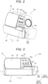
Fig. 2 is a perspective view of the infusion pump illustrated inFig. 1 . -
Fig. 3 is a front view of a state where a door unit of the infusion pump illustrated inFig. 1 is closed. -
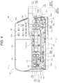
Fig. 4 is a front view of a state where the door unit of the infusion pump illustrated inFig. 1 is opened. -
Fig. 5 is a side view of the infusion pump illustrated inFig. 4 . -
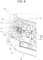
Fig. 6 is an enlarged perspective view of a downstream-side tube guide part and the vicinity thereof of the infusion pump illustrated inFig. 4 . -
Fig. 7 is a side view of the infusion pump illustrated inFig. 3 . -
Fig. 8 is a block diagram of the infusion pump illustrated inFig. 1 . -
Fig. 9 is a diagram illustrating a tube clamp part of the infusion pump illustrated inFig. 4 . -
Fig. 10 is a cross-sectional view of the infusion pump taken along a line I-I' illustrated inFig. 4 . - Hereinafter, an infusion pump according to an embodiment of the present disclosure will be described with reference to the drawings. In the drawings, common members and parts are denoted by the same reference signs. In the description of the present embodiment, the description of the common members and parts will be omitted or simplified as appropriate.
-
Fig. 1 is a diagram illustrating aninfusion line 200 formed by connecting aninfusion container 201 containing a liquid such as a drug solution to an indwellingneedle 202 indwelled in a state of puncturing a patient with atube 203 as an infusion tube. Hereinafter, theinfusion container 201 side of theinfusion line 200 may be referred to as a "flow path upstream side". In addition, the indwellingneedle 202 side of theinfusion line 200 may be referred to as a "flow path downstream side". Further, hereinafter, a direction from the flow path upstream side to the flow path downstream side of theinfusion line 200 may be referred to as a liquid delivery direction A. - More specifically, the
infusion line 200 illustrated inFig. 1 includes aninfusion container 201 hung on astand 250, adrip tube 204, anindwelling needle 202, and twotubes 203. The twotubes 203 of theinfusion line 200 are afirst tube 203a connecting theinfusion container 201 to thedrip tube 204, and asecond tube 203b connecting thedrip tube 204 to the indwellingneedle 202. InFig. 1 , a drip probe as a number-of-dropsabnormality detection apparatus 205 is attached to thedrip tube 204 of theinfusion line 200. In addition, inFig. 1 , aninfusion pump 300 as a liquid delivery pump is attached to thesecond tube 203b of theinfusion line 200. In addition, theinfusion pump 300 is fixed to thestand 250. Further, aclamp 206 is attached to thesecond tube 203b of theinfusion line 200 illustrated inFig. 1 on the flow path downstream side from theinfusion pump 300. In the following description, in a case where thefirst tube 203a and thesecond tube 203b are not particularly distinguished from each other, the tubes are simply collectively referred to as thetubes 203. - First, a schematic configuration will be described of the
infusion pump 300 with reference toFigs. 2, 3 , and4 .Fig. 2 is a perspective view of theinfusion pump 300.Fig. 3 is a front view of a state where adoor unit 302 of theinfusion pump 300 is closed with respect to amain body unit 301.Fig. 4 is a front view of a state where thedoor unit 302 of theinfusion pump 300 is opened with respect to themain body unit 301. InFigs. 2 to 4 , thesecond tube 203b ofFig. 1 held by theinfusion pump 300 is indicated by a two-dot chain line for convenience of description. InFigs. 3 and4 , theinfusion pump 300 is illustrated in a front view of theinfusion pump 300. InFigs. 3 and4 (front view of the infusion pump 300), the left-right direction is also referred to as a "width direction" of theinfusion pump 300, and the up-down direction is also referred to as a "height direction" of theinfusion pump 300. The front-back direction is also referred to as a "depth direction" of theinfusion pump 300. - The
infusion pump 300 illustrated inFigs. 2 to 4 is a liquid delivery pump used, for example, in an intensive care unit (ICU, CCU, NICU) or the like, and used to inject a liquid such as an anticancer agent, an anesthetic, a chemotherapeutic agent, a blood transfusion, or a nutrient for a patient for a relatively long time with an accuracy within ±10% (preferably an accuracy within ±3%) in a range of about 1 to 1200 mL/h (amount of injection per hour, that is, injection rate), 1 to 9999 mL (scheduled amount of injection). - The
infusion pump 300 includes themain body unit 301 and thedoor unit 302 that can be opened and closed with respect to themain body unit 301. Amain body cover 303 that is an exterior cover of themain body unit 301, and thedoor unit 302 described above are molded using a molding resin material having chemical resistance. - First, elements will be described arranged in the
main body cover 303 of themain body unit 301 of theinfusion pump 300. As illustrated inFigs. 2 to 4 , adisplay unit 304 and anoperation panel unit 305 are arranged on a front portion of themain body cover 303. Thedisplay unit 304 is an image display apparatus such as a color liquid crystal display apparatus. Thedisplay unit 304 is located on the left side of a front upper portion of themain body cover 303 and is arranged above thedoor unit 302. - On the
display unit 304, a scheduled amount of injection (mL) of administration, an integrated amount (mL) of administration, a charge history, an injection rate (mL/h), and the like are displayed. In addition, a warning message may be displayed on thedisplay unit 304. - The
operation panel unit 305 is arranged on the right side of the front upper portion of themain body cover 303. Anoperation button 305a is arranged on theoperation panel unit 305. Theoperation button 305a includes, for example, a power switch button, a fast delivery switch button, a start switch button, a stop switch button, and a menu selection button. - As illustrated in
Figs. 2 to 4 , thedoor unit 302 is attached to a front lower portion of themain body cover 303 so as to be rotatable about rotation axes of twohinges door unit 302 is a plate-like lid extending long along the left-right direction in the front view of theinfusion pump 300 inFigs. 3 and4 . Thedoor unit 302 is configured to be openable and closable with respect to themain body unit 301, and cover atube attachment unit 306 provided in the front lower portion of themain body cover 303 in a state of being closed with respect to themain body unit 301. As a result, theinfusion pump 300 can sandwich and hold thesecond tube 203b made of a flexible thermoplastic resin such as soft vinyl chloride, for example, between thetube attachment unit 306 and thedoor unit 302 in a state where thedoor unit 302 is closed with respect to the main body unit 301 (seeFigs. 2 and 3 ). - The
main body unit 301 includes thetube attachment unit 306 to which the infusion tube 203 (thesecond tube 203b in the present embodiment) is attached substantially horizontally. As illustrated inFig. 4 , thetube attachment unit 306 is provided along the left-right direction below thedisplay unit 304 and theoperation panel unit 305 in the front view of theinfusion pump 300. - In the present disclosure, "substantially horizontal" preferably means horizontal, but may include being inclined within a range of a predetermined angle with respect to a horizontal direction (a direction perpendicular to a direction in which gravity acts). The range of the predetermined angle is, for example, a range between -10 degrees and 10 degrees, but is not limited thereto.
- As illustrated in
Fig. 4 , thetube attachment unit 306 defines aguide groove 306a to which thesecond tube 203b is attached. In the present embodiment, theguide groove 306a is continuously provided in thetube attachment unit 306 so as to extend in the left-right direction in the front view of theinfusion pump 300, but may be intermittently provided. Thesecond tube 203b is attached to thetube attachment unit 306 along theguide groove 306a. Thetube attachment unit 306 includes an airbubble detection sensor 307, an upstream-sideocclusion detection sensor 308a, a downstream-sideocclusion detection sensor 308b, an upstream-sidetube guide part 110, a downstream-sidetube guide part 120, a liquiddelivery drive part 312, and atube clamp part 322. More specifically, in thetube attachment unit 306, the upstream-sidetube guide part 110, the airbubble detection sensor 307, the upstream-sideocclusion detection sensor 308a, the liquiddelivery drive part 312, the downstream-sideocclusion detection sensor 308b, thetube clamp part 322, and the downstream-sidetube guide part 120 are arranged in this order from the upstream side in the liquid delivery direction A along theguide groove 306a. Inside thedoor unit 302, atube pressing member 313 and engagingmembers - The
tube pressing member 313 is arranged as a long rectangular planar protruding portion along the left-right direction of theinfusion pump 300 in the front view (seeFig. 4 and the like), and is at a position facing the liquiddelivery drive part 312. The engagingmembers fitting portions main body unit 301 by operation of alever 316 interlocked with the engagingmembers door unit 302 can be closed and thetube attachment unit 306 of themain body unit 301 can be closed. - The
tube clamp part 322 is configured to clamp a part of thesecond tube 203b to fix the infusion tube to thetube attachment unit 306. - A configuration of the
tube clamp part 322 will be described in detail with reference toFig. 9. Fig. 9 is a diagram illustrating thetube clamp part 322 of theinfusion pump 300 illustrated inFig. 4 .Fig. 9(a) is a cross-sectional view of thetube clamp part 322 taken along a line I-I' ofFig. 4 .Fig. 9(b) is a plan view of thetube clamp part 322 in a state where occlusion of thesecond tube 203b is released.Fig. 9(c) is a cross-sectional view of thetube clamp part 322 taken along the line I-I' ofFig. 4 in a state where thesecond tube 203b is occluded. Hereinafter, a state where occlusion of thesecond tube 203b is released is also referred to as an occlusion release state of thesecond tube 203b, and a state where thesecond tube 203b is occluded is also referred to as an occlusion state of thesecond tube 203b. - The
tube clamp part 322 is detachable from thetube attachment unit 306. Specifically, as illustrated inFig. 9(c) , thetube clamp part 322 is fixed to thetube attachment unit 306 by being inserted into thetube attachment unit 306 along an attachment/detachment direction illustrated inFig. 9(c) in a state where a part of thesecond tube 203b is sandwiched between a pair ofocclusion portions tube clamp part 322 is detachable from thetube attachment unit 306 by being pulled out along the attachment/detachment direction from thetube attachment unit 306 in a state where a part of thesecond tube 203b is sandwiched between the pair ofocclusion portions tube clamp part 322 can be attached to or detached from thetube attachment unit 306 in a state where thetube clamp part 322 is attached to thesecond tube 203b in advance and thesecond tube 203b is occluded. - The
tube clamp part 322 includes amain base portion 325 in which oneocclusion portion 323 is formed and asub-base portion 326 in which theother occlusion portion 324 is formed, of the pair ofocclusion portions second tube 203b. Themain base portion 325 and thesub-base portion 326 are integrally formed continuously via a firstelastic support portion 327. The firstelastic support portion 327 is elastically deformable. Then, in the natural state, thesub-base portion 326 is urged in a direction away from themain base portion 325 via the firstelastic support portion 327. Adistal end portion 329 is further formed continuously at an end portion of thesub-base portion 326 on an opposite side from a side continuous with the firstelastic support portion 327 via a secondelastic support portion 328 having an arc shape. The secondelastic support portion 328 is elastically deformable. In the natural state, thedistal end portion 329 is urged in a direction away from theocclusion portion 324 of thesub-base portion 326 via the secondelastic support portion 328. Thetube clamp part 322 includes lockingportions main base portion 325 and thedistal end portion 329 on the opposite side from the side continuous with the firstelastic support portion 327. Specifically, themain base portion 325 includes thefirst locking portion 330 protruding in the attachment/detachment direction of thetube clamp part 322 and thesecond locking portion 331 protruding in a direction orthogonal to the attachment/detachment direction. Thedistal end portion 329 includes thethird locking portion 332 protruding in the attachment/detachment direction and thefourth locking portion 333 protruding in the direction orthogonal to the attachment/detachment direction. - As a result, as illustrated in
Fig. 9(a) , when external force (F1 in the figure) is applied so as to bring themain base portion 325 and thesub-base portion 326 close to each other so as to sandwich a part of thesecond tube 203b by theocclusion portions main base portion 325 and thedistal end portion 329 are separated from each other, thesecond locking portion 331 and thefourth locking portion 333 are locked as illustrated inFig. 9(b) . In a state where thesecond locking portion 331 and thefourth locking portion 333 are locked, thetube clamp part 322 can hold thesecond tube 203b in the occlusion release state without sandwiching thesecond tube 203b by theocclusion portions Fig. 9(b) , when external force (F2 in the figure) is further applied so as to bring themain base portion 325 and thesub-base portion 326 close to each other, from a state where thesecond locking portion 331 and thefourth locking portion 333 are locked, thefirst locking portion 330 and thethird locking portion 332 are locked as illustrated inFig. 9(c) . In a state where thefirst locking portion 330 and thethird locking portion 332 are locked, thetube clamp part 322 can sandwich thesecond tube 203b by theocclusion portions second tube 203b in the occlusion state. Further, as illustrated inFig. 9(c) , when external force (F3 in the figure) is applied in the attachment/detachment direction of thedistal end portion 329, from a state where thefirst locking portion 330 and thethird locking portion 332 are locked, locking of thefirst locking portion 330 and thethird locking portion 332 is released, and thetube clamp part 322 returns to the state (occlusion release state) where thesecond locking portion 331 and thefourth locking portion 333 are locked as illustrated inFig. 9(b) . As described above, the external force F2 or F3 is applied while thesecond tube 203b is held, whereby thetube clamp part 322 can repeat occluding thesecond tube 203b or releasing occlusion of thesecond tube 203b. - Next, with reference to
Fig. 10 , a detailed description will be given of deformation of thetube clamp part 322 accompanying opening and closing of thedoor unit 302 with respect to themain body unit 301.Fig. 10 is a cross-sectional view of theinfusion pump 300 taken along the line I-I' illustrated inFig. 4 . - The
main body unit 301 includes arotating arm member 340 having a rod shape extending from the front side to the back side of themain body unit 301. In the natural state, therotating arm member 340 is urged toward the lower side in the height direction of themain body unit 301 by an urgingmember 342 provided on the back side of themain body unit 301 about arotation shaft 341. The urgingmember 342 is, for example, a spring. In a state where thedoor unit 302 is opened with respect to themain body unit 301, thetube clamp part 322 is inserted into thetube attachment unit 306 from the front side of themain body unit 301 such that thesub-base portion 326 is in contact with therotating arm member 340 from the lower side in the height direction of themain body unit 301. As a result, since external force is applied from therotating arm member 340 to thetube clamp part 322 so that thesub-base portion 326 approaches themain base portion 325, thetube clamp part 322 is in a state where thefirst locking portion 330 and thethird locking portion 332 are locked as illustrated inFig. 9(c) , and can hold thesecond tube 203b in the occlusion state. - Referring again to
Fig. 10 , inside thedoor unit 302, a pressingmember 343 is provided configured to come in contact with and press both therotating arm member 340 and thedistal end portion 329 of thetube clamp part 322 in a state where thedoor unit 302 is closed with respect to themain body unit 301. As a result, when thedoor unit 302 is closed with respect to themain body unit 301, the pressingmember 343 lifts therotating arm member 340 to the upper side in the height direction of themain body unit 301, and presses thedistal end portion 329 toward the back side of themain body unit 301, whereby the locking of thefirst locking portion 330 and thethird locking portion 332 is released and thesecond locking portion 331 and thefourth locking portion 333 are in a state of being locked in thetube clamp part 322 as illustrated inFig. 9(b) , and thesecond tube 203b can be held in the occlusion release state. - As described above, the
tube clamp part 322 is configured to hold thesecond tube 203b attached to thetube attachment unit 306 in the occlusion state in a state where thedoor unit 302 is opened with respect to themain body unit 301, and hold thesecond tube 203b in the occlusion release state in a state where thedoor unit 302 is closed with respect to themain body unit 301 As a result, theinfusion pump 300 can bring thesecond tube 203b into the occlusion state at the time of attachment/detachment of thesecond tube 203b to/from theinfusion pump 300, and bring thesecond tube 203b into the occlusion release state at the time of liquid delivery by theinfusion pump 300. - As illustrated in
Fig. 4 , the upstream-sidetube guide part 110 is provided at the right end of theguide groove 306a of thetube attachment unit 306 in the front view of theinfusion pump 300, and the downstream-sidetube guide part 120 is provided at the left end of theguide groove 306a of thetube attachment unit 306 in the front view of theinfusion pump 300. Then, the upstream-sidetube guide part 110 can hold thesecond tube 203b by fitting the flow path upstream side of thesecond tube 203b of the infusion line 200 (seeFig. 1 ), and the downstream-sidetube guide part 120 can hold thesecond tube 203b by fitting the flow path downstream side of thesecond tube 203b of theinfusion line 200. That is, theinfusion pump 300 can hold thesecond tube 203b substantially horizontally along theguide groove 306a by the upstream-sidetube guide part 110 and the downstream-sidetube guide part 120. As described above, thesecond tube 203b attached substantially horizontally is arranged so as to face the airbubble detection sensor 307, the upstream-sideocclusion detection sensor 308a, the liquiddelivery drive part 312, the downstream-sideocclusion detection sensor 308b, and thetube clamp part 322 in order from the right in the front view ofFig. 4 . However, the upstream-sidetube guide part 110 and the upstream-sideocclusion detection sensor 308a may be arranged at any positions in theguide groove 306a. - A configuration of the downstream-side
tube guide part 120 will be described in detail with reference toFigs. 4 ,5 ,6 , and7 .Fig. 5 is a side view of theinfusion pump 300 illustrated inFig. 4 as viewed from the downstream side in the liquid delivery direction A.Fig. 6 is an enlarged perspective view of the downstream-sidetube guide part 120 and the vicinity thereof of theinfusion pump 300 illustrated inFig. 4 .Fig. 7 is a side view of theinfusion pump 300 illustrated inFig. 3 as viewed from the downstream side in the liquid delivery direction A. - As illustrated in
Figs. 5 and6 , the downstream-sidetube guide part 120 includes anindwelling portion 121 and a first protrudingportion 122. - The indwelling
portion 121 is configured to place thesecond tube 203b on the upper side in the height direction. The indwellingportion 121 is made to extend in the width direction of theinfusion pump 300 so as to form a part of theguide groove 306a, and have a groove shape with an opening on the front side of theinfusion pump 300. As a result, the indwellingportion 121 of the downstream-sidetube guide part 120 can stably hold thesecond tube 203b fitted into the downstream-sidetube guide part 120. - The first protruding
portion 122 is made to have a plate shape, and protrudes from themain body unit 301 to the front side below the indwellingportion 121 in the height direction of themain body unit 301. Specifically, the first protrudingportion 122 has aslope 122S that lies in a row with theindwelling portion 121, extends from the indwellingportion 121 toward the lower side in the height direction, and has a larger degree of protrusion from the main body unit 310 at a position closer to the lower side in the height direction of themain body unit 301. As a result, when a user of the infusion pump 300 places thesecond tube 203b on theindwelling portion 121 of the downstream-sidetube guide part 120, thesecond tube 203b is lifted to the upper side in the height direction along theslope 122S of the first protrudingportion 122, whereby thesecond tube 203b can be attached to theindwelling portion 121. For this reason, thesecond tube 203b can be easily attached to theinfusion pump 300. - More specifically, in the present embodiment, the
slope 122S of the first protrudingportion 122 is curved in an arc shape such that the degree of protrusion from the main body unit 310 increases at a position closer to the lower side in the height direction of themain body unit 301. As a result, when the user of theinfusion pump 300 pushes up thesecond tube 203b along theslope 122S of the first protrudingportion 122 and places thesecond tube 203b on theindwelling portion 121, thesecond tube 203b moves mainly in a tangential direction of the first protrudingportion 122, so that resistance force such as frictional force is less likely to be applied from the first protrudingportion 122 to thesecond tube 203b. In addition, since the first protrudingportion 122 is curved in an arc shape, an inclination of the first protrudingportion 122 with respect to the height direction of the main body unit 310 is gentle at a position closer to a portion that lies in a row with theindwelling portion 121, and thesecond tube 203b placed on theindwelling portion 121 is less likely to be detached from the indwellingportion 121 by its own weight. However, the first protrudingportion 122 does not have to be curved in an arc shape. - As illustrated in
Fig. 7 , the indwellingportion 121 is provided at a position on a side surface in the width direction of themain body unit 301, which is not covered by thedoor unit 302, in a state where thedoor unit 302 is closed with respect to themain body unit 301. As a result, it is possible to reduce a risk of occurrence of occlusion of thesecond tube 203b, underdose of the liquid flowing in thesecond tube 203b, or the like due to the fact that thesecond tube 203b is sandwiched between thedoor unit 302 and themain body unit 301 in a state where thedoor unit 302 is closed with respect to themain body unit 301. - Referring again to
Fig. 6 , the first protrudingportion 122 is provided at a position where the first protrudingportion 122 can come into contact with thesecond tube 203b in a case where thesecond tube 203b fixed by thetube clamp part 322 is in a state of hanging down to the lower side in the height direction of themain body unit 301 by its own weight. Specifically, the first protrudingportion 122 comes in contact with a portion (a portion adjacent to the downstream side in the present embodiment) adjacent to the upstream side or the downstream side of a part of thesecond tube 203b clamped by thetube clamp part 322. As a result, after the user of theinfusion pump 300 fixes thesecond tube 203b to thetube attachment unit 306 by thetube clamp part 322, thesecond tube 203b is easily fitted into the downstream-sidetube guide part 120 along theslope 122S of the first protrudingportion 122. A distance between the first protrudingportion 122 and thetube clamp part 322 in the width direction of theinfusion pump 300 may be set, for example, in a range of 9 mm to 15 mm. - The downstream-side
tube guide part 120 includes an upper protrudingportion 123 in addition to theindwelling portion 121 and the first protrudingportion 122. The upper protrudingportion 123 is made to have a plate shape, and protrudes from themain body unit 301 toward the front side above the indwellingportion 121 in the height direction of themain body unit 301. Specifically, the upper protrudingportion 123 lies in a row with theindwelling portion 121 and extends toward the upper side in the height direction from the indwellingportion 121. The upper protrudingportion 123 includes a slope in which the degree of protrusion from the main body unit 310 increases at a position closer to the upper side in the height direction of themain body unit 301. The upper protrudingportion 123 faces the first protrudingportion 122 in the height direction of themain body unit 301. - The
door unit 302 includes a second protrudingportion 130 that protrudes toward themain body unit 301 in a state where thedoor unit 302 is closed with respect to themain body unit 301. In the present embodiment, as illustrated inFigs. 5 and6 , the second protrudingportion 130 is made to have a plate shape, and is provided at an end portion on the downstream side in the liquid delivery direction A in the width direction of thedoor unit 302. The second protrudingportion 130 is configured to lift thesecond tube 203b to the upper side in the height direction of themain body unit 301 along theslope 122S of the first protrudingportion 122 and place thesecond tube 203b on theindwelling portion 121 when thedoor unit 302 is closed with respect to themain body unit 301. As a result, even in a case where thedoor unit 302 is closed with respect to themain body unit 301 in a state where thesecond tube 203b is not placed on theindwelling portion 121, the second protrudingportion 130 can lift thesecond tube 203b along theslope 122S of the first protrudingportion 122 and place thesecond tube 203b on theindwelling portion 121. For this reason, it is possible to reduce the risk of occurrence of occlusion of thesecond tube 203b, underdose of the liquid flowing in thesecond tube 203b, or the like due to the fact that thesecond tube 203b is sandwiched between thedoor unit 302 and themain body unit 301 when thedoor unit 302 is closed with respect to themain body unit 301. - As illustrated in
Fig. 4 , a distance between the first protrudingportion 122 and the second protrudingportion 130 in the width direction of theinfusion pump 300 in a state where thedoor unit 302 is closed with respect to themain body unit 301 is a distance sufficiently shorter than the diameter of thesecond tube 203b attached to theinfusion pump 300. As a result, when the second protrudingportion 130 lifts the first protrudingportion 122, thesecond tube 203b is less likely to be sandwiched between the first protrudingportion 122 and the second protrudingportion 130. The distance between the first protrudingportion 122 and the second protrudingportion 130 in the width direction of theinfusion pump 300 in a state where thedoor unit 302 is closed with respect to themain body unit 301 may be set, for example, in a range of 0.3 mm to 1.5 mm. - In addition, as illustrated in
Fig. 4 , in a state where thedoor unit 302 is closed with respect to themain body unit 301, the second protrudingportion 130 is located on the opposite side from thetube clamp part 322 with the first protrudingportion 122 interposed therebetween in the width direction of themain body unit 301. That is, the first protrudingportion 122 is located between the second protrudingportion 130 and thetube clamp part 322 in the width direction of themain body unit 301 in a state where thedoor unit 302 is closed with respect to themain body unit 301. As a result, in a case where thesecond tube 203b is in a state of being fixed by thetube clamp part 322 and hanging down to the lower side in the height direction by its own weight, the second protrudingportion 130 more stably lifts thesecond tube 203b along theslope 122S of the first protrudingportion 122. In addition, the second protrudingportion 130 constituting thedoor unit 302 covers the first protrudingportion 122 from the outside in the width direction of themain body unit 301, whereby appearance of theinfusion pump 300 is improved. However, the second protrudingportion 130 may be located between thetube clamp part 322 and the first protrudingportion 122 in the width direction of themain body unit 301 in a state where thedoor unit 302 is closed with respect to themain body unit 301. - As illustrated in
Fig. 5 , in the first protrudingportion 122 of the downstream-sidetube guide part 120, a portion where the degree of protrusion from themain body unit 301 increases protrudes to the front side of themain body unit 301 from the rotation axis of thehinges main body unit 301. As a result, when thedoor unit 302 is closed with respect to themain body unit 301, the second protrudingportion 130 rotating about the rotation axes of thehinges second tube 203b along theslope 122S of the first protrudingportion 122. - Referring to
Fig. 4 , the upstream-sidetube guide part 110 includes an upper protrudingportion 111 located above theguide groove 306a and a lower protrudingportion 112 located below theguide groove 306a in the height direction of themain body unit 301. The upper protrudingportion 111 and the lower protrudingportion 112 face each other across theguide groove 306a in the height direction of themain body unit 301. As a result, thesecond tube 203b is fitted between the upper protrudingportion 111 and the lower protrudingportion 112, whereby the upstream-sidetube guide part 110 holds thesecond tube 203b in theguide groove 306a. In the present embodiment, the upstream-sidetube guide part 110 has a configuration different from that of the downstream-sidetube guide part 120, but the upstream-sidetube guide part 110 may also have a configuration similar to that of the downstream-sidetube guide part 120. - The air
bubble detection sensor 307 is an apparatus that detects a bubble (air) contained in the liquid flowing in thesecond tube 203b. - The air
bubble detection sensor 307 includes a transmitter and a receiver facing each other across a groove portion constituting a part of theguide groove 306a. In the present embodiment, the transmitter and the receiver of the airbubble detection sensor 307 face each other in the groove width direction of the groove portion. The airbubble detection sensor 307 transmits a signal from the transmitter toward thesecond tube 203b accommodated in the groove portion, and applies the signal to the liquid flowing in thesecond tube 203b from the outside of thesecond tube 203b made of soft vinyl chloride, for example. At this time, since a transmittance of the signal in the liquid is different from a transmittance of the signal in the bubble, even in a case where the same signals are transmitted from the transmitter, a difference occurs between the signals received by the receiver depending on whether the bubble is included in the liquid flowing through thesecond tube 203b. The signal transmitted from the transmitter is, for example, an ultrasonic wave, but is not limited thereto. As described above, the airbubble detection sensor 307 can detect the bubble contained in the liquid flowing in thesecond tube 203b on the basis of the difference between the signals received by the receiver. The airbubble detection sensor 307 is communicably connected to anacquisition unit 351 described later by wired communication or wireless communication. As a result, the airbubble detection sensor 307 can transmit, for example, information such as a signal received by the receiver to theacquisition unit 351 as bubble detection information. - The upstream-side
occlusion detection sensor 308a and the downstream-sideocclusion detection sensor 308b are apparatuses that detect whether or not thesecond tube 203b attached to theinfusion pump 300 is occluded. As illustrated inFig. 4 , the upstream-sideocclusion detection sensor 308a is arranged on the upstream side from the liquiddelivery drive part 312 in theguide groove 306a of thetube attachment unit 306. Then, the downstream-sideocclusion detection sensor 308b is arranged on the downstream side from the liquiddelivery drive part 312 in theguide groove 306a of thetube attachment unit 306. In the present embodiment, the upstream-sideocclusion detection sensor 308a and the downstream-sideocclusion detection sensor 308b are made to have the same configuration. In the following description, in a case where the upstream-sideocclusion detection sensor 308a and the downstream-sideocclusion detection sensor 308b are not distinguished from each other, they are simply collectively referred to asocclusion detection sensors 308. - The
occlusion detection sensor 308 includes, for example, a Hall element and a plunger that is movable with respect to the Hall element and includes a magnet. A detection surface exposed to a groove portion constituting a part of theguide groove 306a is provided at one end portion of the plunger. When the inside of thesecond tube 203b attached to theguide groove 306a of thetube attachment unit 306 is occluded, the diameter of thesecond tube 203b changes, and a pressure applied from thesecond tube 203b to the detection surface changes. In theocclusion detection sensor 308, the magnet moves relative to the Hall element following the pressure applied from thesecond tube 203b to the detection surface, so that the Hall element detects a change in magnetic flux. As a result, theocclusion detection sensor 308 can detect the pressure applied to the detection surface and detect whether or not the inside of thesecond tube 203b is occluded. However, theocclusion detection sensor 308 may be any apparatus capable of detecting the pressure applied to the detection surface, such as a strain gauge. - Referring again to
Fig. 4 , on the inner surface side of thedoor unit 302, a first pressingmember 309a, a secondpressing member 309b, and a thirdpressing member 309c are provided at positions facing the airbubble detection sensor 307, the upstream-sideocclusion detection sensor 308a, and the downstream-sideocclusion detection sensor 308b, respectively, in a state where thedoor unit 302 is closed with respect to themain body unit 301. When thedoor unit 302 is closed as illustrated inFig. 3 after thesecond tube 203b is attached to thetube attachment unit 306 as illustrated inFig. 4 , the first pressingmember 309a, the second pressingmember 309b, and the thirdpressing member 309c on thedoor unit 302 side can press thesecond tube 203b against the airbubble detection sensor 307, the upstream-sideocclusion detection sensor 308a, and the downstream-sideocclusion detection sensor 308b, respectively. For this reason, even in a case where a plurality of types of thesecond tubes 203b having slight variations in outer diameter due to manufacturing tolerances or the like are attached to theinfusion pump 300, the airbubble detection sensor 307, the upstream-sideocclusion detection sensor 308a, and the downstream-sideocclusion detection sensor 308b can more accurately detect an abnormality of thesecond tube 203b in a state where thedoor unit 302 is closed with respect to themain body unit 301. In the following description, in a case where the first pressingmember 309a, the second pressingmember 309b, and the thirdpressing member 309c are not particularly distinguished from each other, they are simply collectively referred to as pressing members 309. - As illustrated in
Fig. 8 , theinfusion pump 300 includes theacquisition unit 351, anotification unit 352, and acontrol unit 353.Fig. 8 is a block diagram of theinfusion pump 300. InFig. 8 , for convenience of description, a configuration of the liquiddelivery drive part 312 capable of delivering liquid in thesecond tube 203b is also illustrated. - The liquid
delivery drive part 312 includes adrive motor 312a, acam structure 312b including a plurality of cams rotationally driven by thedrive motor 312a, and afinger structure 312c including a plurality of fingers moved by the cams of thecam structure 312b. Then, thefinger structure 312c of the liquiddelivery drive part 312 is arranged in the tube attachment unit 306 (seeFig. 4 ) described above. Thecam structure 312b includes a plurality of cams, for example, sixcams 319a to 319f, and thefinger structure 312c includes sixfingers 320a to 320f corresponding to the sixcams 319a to 319f. The sixcams 319a to 319f are arranged with a phase difference from each other, and thecam structure 312b is connected to anoutput shaft 321 of thedrive motor 312a. The liquiddelivery drive part 312 sequentially drives the fingers from the upstream side toward the downstream side of thesecond tube 203b in the extending direction of thesecond tube 203b. As a result, thesecond tube 203b is sequentially pressed and closed from the upstream side toward the downstream side of thesecond tube 203b, and performs peristaltic movement. For that reason, the liquiddelivery drive part 312 can deliver the liquid in thesecond tube 203b from the upstream side toward the downstream side of thesecond tube 203b. - The
acquisition unit 351 includes one or more communication interfaces. Theacquisition unit 351 is configured to be able to acquire various types of information from other components constituting theinfusion pump 300 by wired communication or wireless communication. However, theacquisition unit 351 may be configured to be able to transmit information in addition to receiving the various types of information described above. For example, theacquisition unit 351 may be able to transmit the received various types of information to an external apparatus such as a server. - For example, the
acquisition unit 351 can acquire, from the occlusion detection sensors 308 (the upstream-sideocclusion detection sensor 308a and the downstream-sideocclusion detection sensor 308b), pressure information detected by theocclusion detection sensors 308. The pressure information detected by theocclusion detection sensor 308 is, for example, information such as an amount of change in magnetic flux detected by the Hall element of theocclusion detection sensor 308. - In addition, for example, the
acquisition unit 351 can acquire the bubble detection information from the airbubble detection sensor 307. The bubble detection information is, for example, a signal itself received by a reception unit of the airbubble detection sensor 307. - In addition, for example, the
acquisition unit 351 can acquire operation mode information on theinfusion pump 300. Specifically, the operation panel unit 305 (seeFig. 3 and the like) of theinfusion pump 300 includes a plurality ofoperation buttons 305a, and theacquisition unit 351 acquires the operation mode information depending on information input from theoperation panel unit 305. More specifically, when the fast delivery switch button or the start switch button is pressed by an operator, theacquisition unit 351 acquires, as the operation mode information, liquid delivery mode information for executing a liquid delivery mode in which the liquiddelivery drive part 312 is driven to perform liquid delivery. In addition, when the stop switch button is pressed by the operator in a state where theinfusion pump 300 is in the liquid delivery mode, theacquisition unit 351 acquires, as the operation mode information, liquid delivery stop mode information for executing a liquid delivery stop mode in which the liquiddelivery drive part 312 is not driven and liquid delivery is not performed. - In addition, for example, the
acquisition unit 351 can acquire opened/closed state information on thedoor unit 302 with respect to themain body unit 301 of theinfusion pump 300. Specifically, when the engagingmembers 314 and 315 (seeFig. 4 ) of thedoor unit 302 are fitted into thefitting portions 317 and 318 (seeFig. 4 ) formed in themain body unit 301, respectively, theacquisition unit 351 acquires, as the opened/closed state information, closed state information indicating that thedoor unit 302 is in a closed state with respect to themain body unit 301. On the other hand, when the engagingmembers 314 and 315 (seeFig. 4 ) of thedoor unit 302 are not in a state of being fitted into thefitting portions 317 and 318 (seeFig. 4 ) formed in themain body unit 301, respectively, theacquisition unit 351 acquires, as the opened/closed state information, opened state information indicating that thedoor unit 302 is in a state of being opened with respect to themain body unit 301. - As described above, the
acquisition unit 351 can acquire information based on the operation of theinfusion pump 300 itself by the operator, and can acquire information transmitted from components such as the airbubble detection sensor 307 and theocclusion detection sensor 308. - In addition, the
acquisition unit 351 in the present embodiment acquires the bubble detection information from the airbubble detection sensor 307, the pressure information from theocclusion detection sensor 308, the operation mode information on theinfusion pump 300, and the opened/closed state information on thedoor unit 302 described above, but may be made to have a configuration capable of acquiring only some of the various types of information described above, or may be made to have a configuration capable of acquiring other information in addition to the various types of information described above. - The
notification unit 352 includes one or more output apparatuses. The output apparatus included in thenotification unit 352 is, for example, a display, a speaker, a vibrator, or the like. Thenotification unit 352 outputs an image, sound, vibration, or the like. - In the present embodiment, the
notification unit 352 notifies the outside of the information acquired by theacquisition unit 351 as perceptual identification information that can be identified by a human on the basis of a control command from thecontrol unit 353 described later. In the present disclosure, the "perceptual identification information" includes any information perceivable by five human senses, such as an alarm by sound as auditory identification information, and display of a color change, turning on, turning off, blinking, or the like of light of an LED or the like as visual identification information. - The
control unit 353 performs instruction on operation timing or operation for each unit of theinfusion pump 300, or the like. Thecontrol unit 353 includes a processor such as a CPU or an MPU. More specifically, thecontrol unit 353 of the present embodiment includes a read only memory (ROM), a random access memory (RAM), a non-volatile memory, and a clock. The clock can correct a current time by a predetermined operation, and can execute acquisition of the current time, measurement of an elapsed time of a predetermined liquid delivery work, measurement of a reference time of speed control of liquid delivery, and the like. - In addition, the
control unit 353 is connected to a power switch button and a switch. The switch switches between a power converter unit and a rechargeable battery such as a lithium ion battery, to supply power to thecontrol unit 353 from either the power converter unit or the rechargeable battery. The power converter unit is connected to a commercial AC power supply via an outlet. - In addition, the
control unit 353 instructs a display unit driver to drive thedisplay unit 304, and displays the scheduled amount of injection (mL) of administration described above, or various warning messages or the like on thedisplay unit 304. - In addition, the
control unit 353 controls thenotification unit 352 on the basis of the various types of information acquired by theacquisition unit 351. For example, in a case where it is determined that an abnormality of thesecond tube 203b attached to theinfusion pump 300 is detected on the basis of the information from the airbubble detection sensor 307 or theocclusion detection sensor 308 acquired by theacquisition unit 351, thecontrol unit 353 controls thenotification unit 352 to perform notification of the perceptual identification information. For example, thecontrol unit 353 may display a warning message on thedisplay unit 304 as thenotification unit 352. Alternatively, thecontrol unit 353 may cause a speaker as thenotification unit 352 to output a warning sound. As a result, it is possible to urge a user of theinfusion pump 300 to take measures, and improvement is achieved of safety of theinfusion pump 300, and of usefulness of a technique for detecting an abnormality of theinfusion tube 203 attached to theinfusion pump 300. - In addition, the
control unit 353 controls, for example, the liquiddelivery drive part 312 on the basis of the various types of information acquired by theacquisition unit 351. For example, in a case where it is determined that an abnormality of thesecond tube 203b is detected on the basis of the information from the airbubble detection sensor 307 or theocclusion detection sensor 308 acquired by theacquisition unit 351, thecontrol unit 353 may stop driving of the liquiddelivery drive part 312 and end the liquid delivery mode in which liquid delivery is executed. As a result, improvement is achieved of safety of theinfusion pump 300, and of usefulness of the technique for detecting an abnormality of theinfusion tube 203 attached to theinfusion pump 300. - As described above, the infusion pump 300 according to the present embodiment includes the main body unit 301 including the tube attachment unit 306 to which the infusion tube 203 (the second tube 203b in the present embodiment) is attached substantially horizontally, and the door unit 302 that is openable and closable with respect to the main body unit 301 and covers the tube attachment unit 306 in a state of being closed with respect to the main body unit 301, in which: the tube attachment unit 306 includes the indwelling portion 121 configured to place the infusion tube 203 on the upper side in the height direction of the main body unit 301, and the first protruding portion 122 that lies in a row with the indwelling portion 121, extends from the indwelling portion 121 toward the lower side in the height direction of the main body unit 301, and includes the slope 122S in which the degree of protrusion from the main body unit 301 is larger at a position closer to the lower side in the height direction of the main body unit 301; the door unit 302 includes the second protruding portion 130 protruding toward the main body unit 301 in a state where the door unit 302 is closed with respect to the main body unit 301; and the second protruding portion 130 is configured to lift the infusion tube 203 to the upper side in the height direction of the main body unit 301 along the slope 122S of the first protruding portion 122 and place the infusion tube 203 on the indwelling portion 121 when the door unit 302 is closed with respect to the main body unit 301.
- With the
infusion pump 300 having such a configuration, even in a case where thedoor unit 302 is closed with respect to themain body unit 301 in a state where theinfusion tube 203 is not placed on theindwelling portion 121, the second protrudingportion 130 can lift the infusion tube along theslope 122S of the first protrudingportion 122 and place theinfusion tube 203 on theindwelling portion 121. For this reason, it is possible to reduce a risk of occurrence of occlusion of theinfusion tube 203, underdose of the liquid flowing in theinfusion tube 203, or the like due to the fact that theinfusion tube 203 is sandwiched between thedoor unit 302 and themain body unit 301 when thedoor unit 302 is closed with respect to themain body unit 301. Thus, with theinfusion pump 300 according to the present embodiment, it is possible to improve ease of attachment of theinfusion tube 203 on theinfusion pump 300. - Although the present disclosure has been described with reference to the drawings and examples, it should be noted that those skilled in the art can make various modifications and corrections on the basis of the present disclosure. Thus, it should be noted that these modifications and corrections fall within the scope of the present disclosure. For example, functions and the like included in means, steps, and the like can be rearranged so as not to be logically inconsistent, and a plurality of means, steps, and the like can be combined into one, or divided.
- The present disclosure relates to an infusion pump.
-
- 110 Upstream-side tube guide part
- 111 Upper protruding portion
- 112 Lower protruding portion
- 120 Downstream-side tube guide part
- 121 Indwelling portion
- 122 First protruding portion
- 122S Slope
- 123 Upper protruding portion
- 130 Second protruding portion
- 200 Infusion line
- 201 Infusion container
- 202 Indwelling needle
- 203 Tube (infusion tube)
- 203a First tube
- 203b Second tube
- 204 Drip tube
- 205 Number-of-drops abnormality detection apparatus
- 206 Clamp
- 250 Stand
- 300 Infusion pump
- 301 Main body unit
- 302 Door unit
- 302a, 302b Hinge
- 303 Main body cover
- 304 Display unit
- 305 Operation panel unit
- 305a Operation button
- 306 Tube attachment unit
- 306a Guide groove
- 307 Air bubble detection sensor
- 308 Occlusion sensor
- 308a Upstream-side occlusion sensor
- 308b Downstream-side occlusion sensor
- 309 Pressing member
- 309a First pressing member
- 309b Second pressing member
- 309c Third pressing member
- 312 Liquid delivery drive part
- 312a Drive motor
- 312b Cam structure
- 312c Finger structure
- 313 Tube pressing member
- 314, 315 Engaging member
- 316 Lever
- 317, 318 Fitting portion
- 319a to 319f Cam
- 320a to 320f Finger
- 321 Output shaft
- 322 Tube clamp part
- 323, 324 Occlusion portion
- 325 Main base portion
- 326 Sub-base portion
- 327 First elastic support portion
- 328 Second elastic support portion
- 329 Distal end part
- 330 First locking portion
- 331 Second locking portion
- 332 Third locking portion
- 333 Fourth locking portion
- 340 Rotating arm member
- 341 Rotation shaft
- 342 Urging member
- 343 Pressing member
- 351 Acquisition unit
- 352 Notification unit
- 353 Control unit
- A Liquid delivery direction
- I-I' Cut surface
- F1, F2, F3 External force
-
FIG. 3 - HEIGHT DIRECTION
- WIDTH DIRECTION
-
FIG. 4 - HEIGHT DIRECTION
- WIDTH DIRECTION
-
FIG. 5 - HEIGHT DIRECTION
-
FIG. 7 - HEIGHT DIRECTION
-
FIG. 8 - 351 ACQUISITION UNIT
- 352 NOTIFICATION UNIT
- 353 CONTROL UNIT
-
FIG. 9 - ATTACHMENT/DETACHMENT DIRECTION
-
FIG. 10 - HEIGHT DIRECTION
- ATTACHMENT/DETACHMENT DIRECTION
Claims (7)
- An infusion pump comprising:a main body unit including a tube attachment unit to which an infusion tube is attached substantially horizontally; anda door unit that is openable and closable with respect to the main body unit and covers the tube attachment unit in a state of being closed with respect to the main body unit, whereinthe tube attachment unit includesan indwelling portion configured to place the infusion tube on an upper side in a height direction of the main body unit, anda first protruding portion that lies in a row with the indwelling portion, extends from the indwelling portion toward a lower side in the height direction of the main body unit, and includes a slope in which a degree of protrusion from the main body unit is larger at a position closer to the lower side in the height direction,the door unit includes a second protruding portion that protrudes toward the main body unit in a state where the door unit is closed with respect to the main body unit, andthe second protruding portion is configured to lift the infusion tube to the upper side in the height direction along the slope of the first protruding portion and place the infusion tube on the indwelling portion when the door unit is closed with respect to the main body unit.
- The infusion pump according to claim 1, wherein the slope of the first protruding portion is curved in an arc shape such that the degree of protrusion from the main body unit is larger at a position closer to the lower side in the height direction.
- The infusion pump according to claim 1 or 2, wherein the indwelling portion is provided at a position that is on a side surface in a width direction of the main body unit and is not covered by the door unit, in a state where the door unit is closed with respect to the main body unit.
- The infusion pump according to any one of claims 1 to 3, whereinthe tube attachment unit includes a tube clamp part configured to clamp a part of the infusion tube to fix the infusion tube to the tube attachment unit, andthe first protruding portion is provided at a position where the first protruding portion is enabled to come into contact with the infusion tube in a case where the infusion tube fixed by the tube clamp part is in a state of hanging down to the lower side in the height direction by an own weight of the infusion tube.
- The infusion pump according to claim 4, wherein the tube clamp part is configured to hold the infusion tube in an occlusion state in a state where the door unit is opened with respect to the main body unit, and hold the infusion tube in an occlusion release state in a state where the door unit is closed with respect to the main body unit.
- The infusion pump according to claim 4 or 5, wherein the tube clamp part is detachable from the tube attachment unit.
- The infusion pump according to any one of claims 4 to 6, wherein the second protruding portion is located on an opposite side from the tube clamp part with the first protruding portion interposed therebetween in the width direction of the main body unit in a state where the door unit is closed with respect to the main body unit.
Applications Claiming Priority (2)
| Application Number | Priority Date | Filing Date | Title |
|---|---|---|---|
| JP2022020838 | 2022-02-14 | ||
| PCT/JP2023/004057 WO2023153411A1 (en) | 2022-02-14 | 2023-02-07 | Infusion pump |
Publications (2)
| Publication Number | Publication Date |
|---|---|
| EP4473986A1 true EP4473986A1 (en) | 2024-12-11 |
| EP4473986A4 EP4473986A4 (en) | 2025-01-22 |
Family
ID=87564398
Family Applications (1)
| Application Number | Title | Priority Date | Filing Date |
|---|---|---|---|
| EP23752875.7A Pending EP4473986A4 (en) | 2022-02-14 | 2023-02-07 | INFUSION PUMP |
Country Status (5)
| Country | Link |
|---|---|
| US (1) | US20240374812A1 (en) |
| EP (1) | EP4473986A4 (en) |
| JP (1) | JPWO2023153411A1 (en) |
| CN (1) | CN118019554A (en) |
| WO (1) | WO2023153411A1 (en) |
Family Cites Families (9)
| Publication number | Priority date | Publication date | Assignee | Title |
|---|---|---|---|---|
| DE29724578U1 (en) * | 1997-04-18 | 2002-03-28 | Société des Produits Nestlé S.A., Vevey | Peristaltic pump |
| JP3939852B2 (en) * | 1998-03-31 | 2007-07-04 | 日機装株式会社 | Infusion device |
| JP4369139B2 (en) * | 2002-06-17 | 2009-11-18 | テルモ株式会社 | Clamp and infusion device using the same |
| JP2011212112A (en) * | 2010-03-31 | 2011-10-27 | Terumo Corp | Infusion pump |
| US20140371707A1 (en) * | 2011-01-26 | 2014-12-18 | Sean Y. Sullivan | Method and device for insertion of tubing into irrigation and infusion fluid pumps |
| JP5740187B2 (en) | 2011-03-23 | 2015-06-24 | テルモ株式会社 | Infusion pump |
| JP6114258B2 (en) * | 2012-03-26 | 2017-04-12 | テルモ株式会社 | Infusion pump |
| WO2020153036A1 (en) * | 2019-01-22 | 2020-07-30 | テルモ株式会社 | Liquid delivery pump |
| CN211751512U (en) * | 2019-11-15 | 2020-10-27 | 深圳迈瑞科技有限公司 | Infusion pump |
-
2023
- 2023-02-07 WO PCT/JP2023/004057 patent/WO2023153411A1/en not_active Ceased
- 2023-02-07 EP EP23752875.7A patent/EP4473986A4/en active Pending
- 2023-02-07 JP JP2023580274A patent/JPWO2023153411A1/ja active Pending
- 2023-02-07 CN CN202380013629.7A patent/CN118019554A/en active Pending
-
2024
- 2024-07-23 US US18/780,934 patent/US20240374812A1/en active Pending
Also Published As
| Publication number | Publication date |
|---|---|
| EP4473986A4 (en) | 2025-01-22 |
| WO2023153411A1 (en) | 2023-08-17 |
| US20240374812A1 (en) | 2024-11-14 |
| CN118019554A (en) | 2024-05-10 |
| JPWO2023153411A1 (en) | 2023-08-17 |
Similar Documents
| Publication | Publication Date | Title |
|---|---|---|
| EP2700424B1 (en) | Infusion pump | |
| CN104582752B (en) | Infusion pump | |
| JP6207516B2 (en) | Infusion pump | |
| JP6023200B2 (en) | Infusion pump | |
| US9616170B2 (en) | Infusion pump | |
| JP2016500013A (en) | Fluid supply system and method | |
| JPWO2014118944A1 (en) | Infusion pump comprising an infusion probe and an infusion probe | |
| JP5996843B2 (en) | Infusion pump | |
| WO2014049656A1 (en) | Infusion pump | |
| JP5805415B2 (en) | Infusion pump | |
| JP2012029915A (en) | Infusion pump | |
| US20240366861A1 (en) | Infusion Pump | |
| JP5740187B2 (en) | Infusion pump | |
| US20240374812A1 (en) | Infusion Pump | |
| WO2014045324A1 (en) | Medical pump | |
| JP2005013413A (en) | Transfusion apparatus | |
| JP6276823B2 (en) | Infusion pump | |
| JP3124022U (en) | Infusion device | |
| WO2013125576A1 (en) | Medical pump | |
| JP2012200422A (en) | Infusion pump | |
| WO2012132350A1 (en) | Infusion pump | |
| WO2014030184A1 (en) | Infusion pump | |
| WO2023149342A1 (en) | Air bubble detection device and infusion pump | |
| WO2014045328A1 (en) | Infusion pump | |
| EP4659775A1 (en) | Tube void determination device and liquid delivery pump |
Legal Events
| Date | Code | Title | Description |
|---|---|---|---|
| STAA | Information on the status of an ep patent application or granted ep patent |
Free format text: STATUS: THE INTERNATIONAL PUBLICATION HAS BEEN MADE |
|
| PUAI | Public reference made under article 153(3) epc to a published international application that has entered the european phase |
Free format text: ORIGINAL CODE: 0009012 |
|
| STAA | Information on the status of an ep patent application or granted ep patent |
Free format text: STATUS: REQUEST FOR EXAMINATION WAS MADE |
|
| 17P | Request for examination filed |
Effective date: 20240902 |
|
| AK | Designated contracting states |
Kind code of ref document: A1 Designated state(s): AL AT BE BG CH CY CZ DE DK EE ES FI FR GB GR HR HU IE IS IT LI LT LU LV MC ME MK MT NL NO PL PT RO RS SE SI SK SM TR |
|
| A4 | Supplementary search report drawn up and despatched |
Effective date: 20250102 |
|
| RIC1 | Information provided on ipc code assigned before grant |
Ipc: A61M 39/08 20060101ALN20241218BHEP Ipc: A61M 5/168 20060101ALN20241218BHEP Ipc: A61M 5/36 20060101ALN20241218BHEP Ipc: A61M 5/14 20060101ALN20241218BHEP Ipc: A61M 39/28 20060101ALI20241218BHEP Ipc: A61M 39/10 20060101ALI20241218BHEP Ipc: A61M 5/142 20060101AFI20241218BHEP |
|
| DAV | Request for validation of the european patent (deleted) | ||
| DAX | Request for extension of the european patent (deleted) |