EP4473901A1 - Auslösung der erfassung medizinischer daten unter verwendung von ppg- und bcg-signalen - Google Patents
Auslösung der erfassung medizinischer daten unter verwendung von ppg- und bcg-signalen Download PDFInfo
- Publication number
- EP4473901A1 EP4473901A1 EP23185979.4A EP23185979A EP4473901A1 EP 4473901 A1 EP4473901 A1 EP 4473901A1 EP 23185979 A EP23185979 A EP 23185979A EP 4473901 A1 EP4473901 A1 EP 4473901A1
- Authority
- EP
- European Patent Office
- Prior art keywords
- ppg
- bcg
- signal
- regions
- candidate
- Prior art date
- Legal status (The legal status is an assumption and is not a legal conclusion. Google has not performed a legal analysis and makes no representation as to the accuracy of the status listed.)
- Withdrawn
Links
Images


Classifications
-
- A—HUMAN NECESSITIES
- A61—MEDICAL OR VETERINARY SCIENCE; HYGIENE
- A61B—DIAGNOSIS; SURGERY; IDENTIFICATION
- A61B5/00—Measuring for diagnostic purposes; Identification of persons
- A61B5/103—Measuring devices for testing the shape, pattern, colour, size or movement of the body or parts thereof, for diagnostic purposes
- A61B5/11—Measuring movement of the entire body or parts thereof, e.g. head or hand tremor or mobility of a limb
- A61B5/1102—Ballistocardiography
-
- A—HUMAN NECESSITIES
- A61—MEDICAL OR VETERINARY SCIENCE; HYGIENE
- A61B—DIAGNOSIS; SURGERY; IDENTIFICATION
- A61B5/00—Measuring for diagnostic purposes; Identification of persons
- A61B5/02—Detecting, measuring or recording for evaluating the cardiovascular system, e.g. pulse, heart rate, blood pressure or blood flow
- A61B5/0205—Simultaneously evaluating both cardiovascular conditions and different types of body conditions, e.g. heart and respiratory condition
-
- A—HUMAN NECESSITIES
- A61—MEDICAL OR VETERINARY SCIENCE; HYGIENE
- A61B—DIAGNOSIS; SURGERY; IDENTIFICATION
- A61B5/00—Measuring for diagnostic purposes; Identification of persons
- A61B5/02—Detecting, measuring or recording for evaluating the cardiovascular system, e.g. pulse, heart rate, blood pressure or blood flow
- A61B5/024—Measuring pulse rate or heart rate
- A61B5/02416—Measuring pulse rate or heart rate using photoplethysmograph signals, e.g. generated by infrared radiation
-
- A—HUMAN NECESSITIES
- A61—MEDICAL OR VETERINARY SCIENCE; HYGIENE
- A61B—DIAGNOSIS; SURGERY; IDENTIFICATION
- A61B5/00—Measuring for diagnostic purposes; Identification of persons
- A61B5/103—Measuring devices for testing the shape, pattern, colour, size or movement of the body or parts thereof, for diagnostic purposes
- A61B5/11—Measuring movement of the entire body or parts thereof, e.g. head or hand tremor or mobility of a limb
- A61B5/1126—Measuring movement of the entire body or parts thereof, e.g. head or hand tremor or mobility of a limb using a particular sensing technique
- A61B5/1128—Measuring movement of the entire body or parts thereof, e.g. head or hand tremor or mobility of a limb using a particular sensing technique using image analysis
-
- A—HUMAN NECESSITIES
- A61—MEDICAL OR VETERINARY SCIENCE; HYGIENE
- A61B—DIAGNOSIS; SURGERY; IDENTIFICATION
- A61B5/00—Measuring for diagnostic purposes; Identification of persons
- A61B5/72—Signal processing specially adapted for physiological signals or for diagnostic purposes
- A61B5/7271—Specific aspects of physiological measurement analysis
- A61B5/7285—Specific aspects of physiological measurement analysis for synchronizing or triggering a physiological measurement or image acquisition with a physiological event or waveform, e.g. an ECG signal
- A61B5/7292—Prospective gating, i.e. predicting the occurrence of a physiological event for use as a synchronisation signal
-
- G—PHYSICS
- G01—MEASURING; TESTING
- G01R—MEASURING ELECTRIC VARIABLES; MEASURING MAGNETIC VARIABLES
- G01R33/00—Arrangements or instruments for measuring magnetic variables
- G01R33/20—Arrangements or instruments for measuring magnetic variables involving magnetic resonance
- G01R33/44—Arrangements or instruments for measuring magnetic variables involving magnetic resonance using nuclear magnetic resonance [NMR]
- G01R33/48—NMR imaging systems
- G01R33/54—Signal processing systems, e.g. using pulse sequences ; Generation or control of pulse sequences; Operator console
- G01R33/56—Image enhancement or correction, e.g. subtraction or averaging techniques, e.g. improvement of signal-to-noise ratio and resolution
- G01R33/567—Image enhancement or correction, e.g. subtraction or averaging techniques, e.g. improvement of signal-to-noise ratio and resolution gated by physiological signals, i.e. synchronization of acquired MR data with periodical motion of an object of interest, e.g. monitoring or triggering system for cardiac or respiratory gating
- G01R33/5673—Gating or triggering based on a physiological signal other than an MR signal, e.g. ECG gating or motion monitoring using optical systems for monitoring the motion of a fiducial marker
-
- A—HUMAN NECESSITIES
- A61—MEDICAL OR VETERINARY SCIENCE; HYGIENE
- A61B—DIAGNOSIS; SURGERY; IDENTIFICATION
- A61B5/00—Measuring for diagnostic purposes; Identification of persons
- A61B5/05—Detecting, measuring or recording for diagnosis by means of electric currents or magnetic fields; Measuring using microwaves or radio waves
- A61B5/055—Detecting, measuring or recording for diagnosis by means of electric currents or magnetic fields; Measuring using microwaves or radio waves involving electronic [EMR] or nuclear [NMR] magnetic resonance, e.g. magnetic resonance imaging
Definitions
- the invention relates to camera-based photoplethysmography systems, in particular to a determination of a trigger time for triggering the acquisition of medical data.
- ECG electrocardiogram
- the invention provides for a system, a computer program, and a method in the independent claims. Embodiments are given in the dependent claims.
- Embodiments provide a remote camera-based triggering system for a medical data acquisition system (e.g., magnetic resonance imaging (MRI) system or computerized tomography (CT) system).
- the system has means for separating ballistocardiogram (BCG) signal from photoplethysmogram (PPG) signal.
- BCG ballistocardiogram
- PPG photoplethysmogram
- PPG photoplethysmogram
- PPG photoplethysmogram
- the relation e.g., time offset
- the time offset may enable a seamless transition between trigger creation based on PPG signal or BCG signal.
- the invention provides for a system.
- the system may, for example, be a medical system.
- the system comprises: a memory storing machine executable instructions; and a computational system, wherein execution of the machine executable instructions causes the computational system to: receive video frames of a video which have been acquired from a subject; determine a PPG, signal and a BCG signal from the video frames; determine first markers in the PPG signal; determine second markers in the BCG signal; use a selected first marker of the first markers and/or a selected second marker of the second markers to define a trigger time for acquiring medical data from the subject.
- the medical data may, for example, be acquired from an organ e.g., heart, of the subject.
- the medical data may, for example, be MR data or CT data.
- the video frames may be acquired by an optical imaging system.
- the optical imaging system may be any imaging device capable of acquiring a sequence of images, and preferably is one or more digital video cameras that output digital video frames with a time stamp annotating each frame.
- the image acquired by the optical imaging system may be a video frame.
- the optical imaging system may be remote from the subject. This may enable to measure vital sign information remotely e.g., without having to attach a sensor to the subject.
- the optical imaging system may be configured to acquire the video frames from an imaging zone of the subject.
- the imaging zone may, for example, be the face of the subject.
- the video frames comprise a sequence of frames acquired at successive equally spaced points in time.
- the video frames may be acquired at a given frame rate.
- the frame rate refers to the number of frames per second.
- the optical imaging system may be configured to store and transmit the video frames.
- the PPG signal and the BCG signal may be extracted from the received video frames.
- first markers may be determined in the PPG signal.
- the first markers may be referred to as PPG markers.
- Second markers may be determined in the BCG signal.
- the second markers may be referred to as BCG markers.
- the determined BCG markers may be specific data points in a time window of the BCG signal.
- the time window may, for example, represent one cardiac cycle of the subject.
- the BCG marker may, for example, be any one of: a peak point, an onset point or an offset point.
- the determined PPG markers may be specific data points in a time window of the PPG signal.
- the time window may, for example, represent one cardiac cycle of the subject.
- the PPG marker may, for example, be any one of: a peak point, an onset point or an offset point.
- the amount of first markers and second markers may, thus, be determined according to the time window length.
- the BCG marker may, for example, be created or determined by filtering and transforming the BCG signal.
- the filtering and transforming may, for example, comprise taking the derivative of the BCG signal and detecting the position of a peak point, an onset point, an offset point or a zero-crossing point and providing one of the points as the BCG marker.
- the PPG marker may, for example, be created or determined by filtering and transforming the PPG signal.
- the filtering and transforming may, for example, comprise taking the derivative of the PPG signal and detecting the position of a peak point, an onset point, an offset point or a zero-crossing point and providing one of the points as the PPG marker.
- the BCG markers which are determined in the BCG signal may, for example, comprise a same type or different types of points e.g., the BCG markers may comprise one or more peak points, one or more onset points etc.
- the PPG markers which are determined in the PPG signal may, for example, comprise a same type or different types of points e.g., the PPG markers may comprise one or more peak points, one or more onset points etc.
- One or more BCG markers may be selected from the BCG markers.
- One or more PPG markers may be selected from the PPG markers.
- the number of selected PPG markers may be one selected PPG marker and the number of selected BCG markers may be one selected BCG marker; however, it is not limited to.
- the selected BCG marker may represent a specific point of the cardiac cycle of the subject e.g., the selected BCG marker may represent the beginning of the diastole period or systole period.
- the selection of the BCG marker(s) may be performed using a first selection criterion.
- the first selection criterion may require a maximum number of selected BCG markers e.g., the maximum number may be one.
- the first selection criterion may require that the selected BCG marker is a predefined fiducial point e.g., the selected BCG marker may be a peak point.
- the selection of the PPG marker(s) may be performed using a second selection criterion.
- the second selection criterion may require a maximum number of selected PPG markers e.g., the maximum number may be one.
- the second selection criterion may require that the selected PPG marker is a predefined fiducial point e.g., the selected PPG marker may be a zero-crossing point.
- the selected one or more BCG markers may be used to determine the trigger time for acquiring the medical data from the subject.
- the trigger time may be equal to the time associated with the selected BCG marker.
- selected one or more PPG markers may be used to determine the trigger time for acquiring the medical data from the subject.
- the selected one or more BCG markers and the selected one or more PPG markers may be used to determine the trigger time for acquiring the medical data from the subject.
- the trigger time may be the selected BCG marker plus a given time range "tau", where the time range tau may be calibrated for a specific cardiac phase of the subject or the time range tau may be a user defined time range.
- a table may be provided per scan type, wherein the table comprises for a given BCG marker and a given Inter-Beat-Interval (IBI), the distance (in time) between the BCG marker and the pre-pulse trigger and/or data acquisition window.
- IBI Inter-Beat-Interval
- the table may be used to extract the distance associated with the selected BCG marker and the IBI of the subject, and the extracted distance may be used as the trigger time.
- the extracted distance may be a waiting period for acquiring data after the point of time of the selected BCG marker, wherein the waiting period may be the time the medical system has to wait to shoot the pre-pulse and the acquisition.
- the present subject matter may enable a reliable acquisition of medical data based on accurately determined trigger times using remote camera-based measurements.
- the present subject matter may thus provide an improved alternative of the ECG-based triggering.
- the camera-based measurements may comprise both PPG and BCG information.
- the BCG information can be used for triggering the acquisition of the medical data.
- the PPG information can be used for triggering acquisitions by extracting well-defined markers (e.g., per cardiac cycle).
- the PPG information may lack information on the state of the target organ (the heart).
- the BCG information may be used in combination with PPG for triggering; because BCG contains information on the state of the target organ as it reflects the contraction of the muscles of the heart.
- statistical models may be used in combination with the PPG information to define the trigger time.
- the trigger time may be determined using the selected PPG marker.
- the PPG marker may be associated with a specific point of the cardiac cycle of the subject using a temporal offset. This may further improve the triggering based on PPG markers compared to using the PPG marker only.
- the temporal offset may be used in combination with the selected PPG marker in order to determine the trigger time.
- the selected PPG marker may be shifted by the temporal offset to obtain the trigger time.
- the temporal offset may, for example, be a pulse transit time (PTT) but it is not limited to, because the temporal offset between PPG and BCG signal may be more general as any marker could be target.
- the PTT may be defined as an offset between a marker (indicative for the arrival of the blood bolus) in the PPG signals obtained from different sites of the body.
- the present subject matter may provide alternative offset determination techniques to provide the temporal offset. These offset determination techniques may enable to measure the temporal offset or predict the temporal offset. In case the temporal offset cannot be determined with one offset determination technique, the other offset determination technique may instated be used to determine the temporal offset. For example, in case the measurement of the temporal offset using BCG and PPG signals fails, the temporal offset may be predicted e.g., using a statistical model.
- the temporal offset may be determined one time and then reused for determining the trigger time multiple times. This may save resources that would otherwise be required by a repeated determination of the offset while still providing reliable trigger times.
- the temporal offset may be regularly updated or determined. For example, the temporal offset may be determined each time the PPG marker is selected from a given set of video frames. This may provide an accurate triggering of acquisition of medical data.
- BCG markers and PPG markers are compared to identify unique pairs of BCG marker and PPG marker which, each pair covering a time interval, wherein are the time interval is smaller than one cardiac cycle of the subject.
- the temporal offset may be determined using the time intervals of the identified pairs.
- a pair of BCG marker and PPG marker may be unique if it does not share any marker with any other identified pair of BCG marker and PPG marker.
- the time intervals may be combined to obtain the temporal offset.
- the temporal offset may, for example, be the average of the time intervals.
- the temporal offset may be used in combination with the selected PPG marker in order to determine the trigger time.
- the time of the selected PPG marker may be shifted by the temporal offset.
- the resulting shifted PPG marker may further be shifted by the time range tau or by the extracted distance associated with the identified BCG marker, the identified BCG marker which has a distance to the PPG marker equal to the temporal offset or equal to one of the time intervals.
- the PPG signal and the BCG signal may be segmented into cardiac cycles of the subject.
- Representative cycle waveforms may be generated from the segmented PPG signal and the segmented BCG signal respectively.
- the generated representative cycle waveforms may be used to determine or identify at least one pair of BCG and PPG markers, wherein the temporal offset may be determined using the determined pair of BCG and PPG markers.
- the temporal offset may be the time interval covered by (or between) the pair of BCG and PPG markers.
- the representative cycle waveform computation for both PPG and BCG may deploy the same segmentation for cycle construction.
- a graph extending over one cardiac cycle containing a PPG waveform may be obtained from the extracted PPG signal, wherein the identified PPG marker may be any peak point of the PPG waveform.
- a graph extending over one cardiac cycle containing a BCG waveform may be obtained from the extracted PPG signal, wherein the identified BCG marker may be any zero-crossing point of the BCG waveform.
- This example may result in a pair of identified BCG and PPG markers.
- a time difference between the pair of the identified BCG marker and PPG marker may be computed. This example may be repeated for other cardiac cycles. This may result in multiple time differences of the respective pairs of BCG and PPG markers.
- the temporal offset may, for example, be the average of the time differences.
- the BCG waveforms of multiple cardiac cycles of the extracted BCG signal are averaged to obtain one averaged BCG waveform that represents one cardiac cycle
- the PPG waveforms of multiple cardiac cycles of the extracted PPG signal are averaged to obtain one averaged PPG waveform that represents one cardiac cycle.
- the BCG marker may be identified (e.g., as any peak point) in the averaged BCG waveform and the PPG marker may be identified (e.g., as any zero-crossing point) in the averaged PPG waveform.
- the time difference between the identified pair of BCG and PPG markers may be the temporal offset. This example may have the advantage that the marker positions are better determined because the signal is less noisy after the average waveform determination.
- the example offset determination techniques may be performed as part of the method for determining the trigger time i.e., using the BCG and PPG signals obtained from the (currently) received video frames.
- the example offset determination techniques may be performed as part of a calibration process which may be done before the present method of determining the trigger time is executed e.g., by using BCG and PPG signals which are previously obtained from the subject.
- the temporal offset may be estimated or predicted estimate from population statistics. This may enable to obtain the trigger time using the selected PPG marker only and by deploying coarse offset estimate from population statistics. In this case, the trigger time may, for example, be obtained as the result of shifting the selected PPG marker by the temporal offset.
- the present subject matter may provide accurate triggering of medical data acquisition.
- the medical data acquisition may comprise MRI data acquisition or CT data acquisition.
- the present subject matter may further improve the accuracy of the acquisition triggering by using improved techniques to extract and separate the BCG signal from the PPG signal using the video frames.
- Embodiments may enable the extraction of information in either stream combined with mutual information cross-over of specific signal features.
- the video frame may be a digital image.
- the image may have a spatial resolution.
- the spatial resolution may refer to the number of pixels composing the image.
- region as used herein may refer to a group of adjacent pixels.
- the present subject matter may provide in the video frames first regions which are candidate sources of PPG information.
- the first regions may, for example, be identified in each frame of the received video frames.
- the first regions may be predefined. In this case, their identification may be performed by mapping their definitions to the frames.
- the first regions may be defined (dynamically) during the identification step. For example, a number M of frames may be received.
- Each i -th frame F i of the received M frames may comprise first regions PPG 1 F i ... PPG Ni F i , where the subscript Ni is the number of first regions in the frame F i , where the index i refers to the i -th frame and which is a number between 1 and the total number M of received frames.
- a subset of frames of the received frames may comprise a number of first regions which is smaller than the maximum number of first regions N PPG .
- the identified maximum number of first regions N PPG may be used to determine the PPG signal.
- the PPG signal may be determined by processing frame by frame as follows.
- the PPG signal may comprise one signal value S PPG i per frame F i , e.g., the PPG signal may comprise M signal values: S PPG 1 , ... S PPG M .
- the individual signal values S PPG i may be obtained using different advantageous techniques.
- the PPG signal S PPG may thus be
- the present subject matter may further provide in the received video frames second regions which are candidate sources of BCG information.
- the second regions may, for example, be identified in each frame of received video frames.
- each i -th frame F i of the received M frames may comprise second regions BGG 1 F i ... BCG Li F i , where the subscript Li is the number of second regions in the frame F i , where the index i refers to the i -th frame and which is a number between 1 and the total number M of received frames.
- a subset of frames of the received frames may comprise a number of second regions which is smaller than the maximum number of second regions N BCG .
- the identified maximum number of second regions N BCG may be used to determine N BCG candidate BCG signals, one per second region.
- the N BCG candidate BCG signals may be referred to as S BCG 1 , S BCG 2 ... . S BCG N BCG .
- each candidate BCG signal may be determined by processing frame by frame the received frames as follows. For each k -th second region BCG k , and for each i -th frame F i , one signal value S BGG k F i may be obtained from the second region BGG k F i in the frame by averaging the pixel values in the second region BGG k F i .
- the candidate BCG signal S BCG k for the k -th second region BCG k may comprise the values: S BGG k F 1 , S BGG k F 2 ... S BGG k F M .
- the associated signal value may be set to zero or may be interpolated from the remaining signal values.
- a BCG signal may be built using the selected second regions.
- another alternative method based on clustering may be used to determine the BCG signal S BCG .
- the present subject matter may thus use a remote camera-based PPG and BCG measurement to identify BCG and PPG regions.
- the BCG signals are small, the corresponding regions may be correctly identified according to the present subject matter. This correct region identification may lead to accurate BCG signals.
- the BCG signal may be used in combination with the PPG signal to provide accurate identification of the temporal offset.
- the BCG signals may be used to do triggering and to calibrate (personalize) the PPG triggering by measuring the temporal offset as well.
- the present subject matter may enable accurate and continuous monitoring of the state of the heart as required in for example MRI and CT triggering applications.
- the present subject matter may achieve two objectives at once: a hassle-free measurement (for patient and personnel, e.g., simplifying the workflow) and a proper cardiac gating which may be characterized by a strong coupling to specific features in the ECG cycle, in particular to the R-peak, useable in both prospective and retrospective scanning modes.
- the PPG signal S PPG may be determined as follows.
- the identified maximum number N PPG of first regions may be used to determine N PPG candidate PPG signals, one per first region.
- the N PPG candidate PPG signals may be referred to as S PPG 1 , S PPG 2 ... . S PPG N PPG respectively.
- each candidate PPG signal may be determined by processing frame by frame the received frames as follows. For each k -th first region PPG k , and for each i -th frame F i , one signal value S PPG k F i .
- the candidate PPG signal S PPG k for the k -th first region PPG k may comprise the M values: S PPG k F 1 , S PPG k F 2 ... . S PPG k F M , one per frame.
- the associated signal value may be set to zero or may be estimated e.g., using interpolation from the remaining signal values.
- the candidate PPG signals and the candidate BCG signals may be clustered to obtain one cluster that represents BCG signals and another cluster that represents PPG signals. The clustering may further result in a third cluster which represents other signals different from both the BCG and PPG signals.
- the N PPG + N BCG signals S BCG 1 , S BCG 2 ... S BCG N BCG and S PPG1 , S PPG 2 ... S PPG N PPG may be clustered.
- the signals of the BCG cluster may be combined for obtaining the BCG signal S BCG.
- the signals of the PPG cluster may be combined for obtaining the PPG signal S PPG .
- the combination may, for example, be performed by averaging.
- the clustering may enable to (re-)cluster the candidate BCG and PPG signals to correct for potential improper identifications of the first and second regions.
- the clustering operation may be performed with the aim to remove BCG information which erroneously was identified and used in the construction of the PPG signal. This example may thus further improve the accuracy of the PPT detection.
- the PPG signal S PPG may be determined as follow.
- S PPG N PPG may be selected based on their similarity with the BCG signal S BCG . This may be equivalent to select subset of first regions from the first regions since the candidate PPG signals are associated with the first regions respectively.
- a number N PPG similarity values sim 1 , ..., sim N PPG may, for example, be defined.
- sim 1 similarity ( S BCG , S PGG 1 )
- sim 2 similarity ( S BCG , S PGG 2 )
- sim N PPG similarity S BCG S PGG N PPG .
- the selected first regions may be referred to as PPG 1 ... PGG N PPG sel , where N PPG sel is the number of selected first regions which may be smaller than or equal to the number of identified first regions N PG , N PPG sel ⁇ N PPG .
- the PPG signal may be obtained by combining the selected candidate PPG signals.
- This example may be advantageous because the similarity measure may enable to refine the list of candidate PPG signals to correct for potential improper identifications of the first regions.
- the received video frames are acquired during a breath-hold period of the subject.
- This example may be advantageous because the PPG and in particular BCG signals are most pronounced during breath-holds. Therefore, these periods may enable an efficient identification of BCG regions and PPG regions.
- each frame of the frames comprises the first regions
- determining of the first PPG signal using the first regions comprises: combining pixel values in the first regions of each frame for obtaining one PPG signal value per frame of the frames.
- each frame of the frames comprises the selected second regions, wherein determining the BCG signal using the selected second regions comprises: combining pixel values in the selected second regions of each frame for obtaining one BCG signal value per frame of the frames.
- comparing the set of candidate BCG signals with the first PPG signal comprises correlating the set of candidate BCG signals with the first PPG signal, wherein the similarity values are the correlation values respectively.
- the correlation may provide an accurate similarity metric in particular as the BCG and PPG signals are time domain signals.
- comparing the set of candidate BCG signals with the first PPG signal comprises determining the similarity of the set of candidate BCG signals with the first PPG signal.
- other similarity metrics may be used.
- One example may be to add a term to the correlation function that enhances the correlation if the relative phase of PPG and BCG is in the expected range derived from a typical PTT.
- the assumed or typical PTT range may be derived from prior information such as patient size and weight.
- the correlation function may be defined as max(xcorr( S BBG , S BCG )), where xcorr is the cross-correlation of both signals. The location of this maximum in the cross-correlation defines the relative phase between both signals.
- the enhanced correlation function may be defined as max(xcorr( S PPG , S BCG )[tau - r, tau + r]) where tau is the expective relative phase and r the radius of search (parameter).
- a third correlation function may be defined as: exp(-
- the medical system further comprises a magnetic resonance imaging system
- the memory further contains pulse sequence commands configured to control the magnetic resonance imaging system to acquire k-space data according to the magnetic resonance imaging protocol, wherein execution of the machine executable instructions further causes the computational system to use the PTT to acquire k-space data from the subject by controlling the magnetic resonance imaging system.
- the first regions may be identified by: identifying a working area of skin pixels; creating candidate regions in the working area; correcting signals in each candidate region from external interferences and motion artefacts; selecting the first regions from the candidate regions using the corrected signals.
- the identification of the working area comprises detecting a face area of the subject.
- the invention in another aspect relates to a method comprising: receiving video frames of a video which have been acquired from a subject; determining a photoplethysmogram, PPG, signal and a ballistocardiogram, BCG, signal from the video frames; identifying first markers in the PPG signal; identifying second markers in the BCG signal; defining a trigger time for acquiring medical data from the subject using a selected first marker and/or selected second marker.
- aspects of the present invention may be embodied as an apparatus, method or computer program product. Accordingly, aspects of the present invention may take the form of an entirely hardware embodiment, an entirely software embodiment (including firmware, resident software, micro-code, etc.) or an embodiment combining software and hardware aspects that may all generally be referred to herein as a "circuit,” “module” or “system.” Furthermore, aspects of the present invention may take the form of a computer program product embodied in one or more computer readable medium(s) having computer executable code embodied thereon.
- the computer readable medium may be a computer readable signal medium or a computer readable storage medium.
- a ⁇ computer-readable storage medium' as used herein encompasses any tangible storage medium which may store instructions which are executable by a processor or computational system of a computing device.
- the computer-readable storage medium may be referred to as a computer-readable non-transitory storage medium.
- the computer-readable storage medium may also be referred to as a tangible computer readable medium.
- a computer-readable storage medium may also be able to store data which is able to be accessed by the computational system of the computing device.
- Examples of computer-readable storage media include, but are not limited to: a floppy disk, a magnetic hard disk drive, a solid-state hard disk, flash memory, a USB thumb drive, Random Access Memory (RAM), Read Only Memory (ROM), an optical disk, a magneto-optical disk, and the register file of the computational system.
- Examples of optical disks include Compact Disks (CD) and Digital Versatile Disks (DVD), for example CD-ROM, CD-RW, CD-R, DVD-ROM, DVD-RW, or DVD-R disks.
- the term computer readable-storage medium also refers to various types of recording media capable of being accessed by the computer device via a network or communication link.
- data may be retrieved over a modem, over the internet, or over a local area network.
- Computer executable code embodied on a computer readable medium may be transmitted using any appropriate medium, including but not limited to wireless, wire line, optical fiber cable, RF, etc., or any suitable combination of the foregoing.
- a computer readable signal medium may include a propagated data signal with computer executable code embodied therein, for example, in baseband or as part of a carrier wave. Such a propagated signal may take any of a variety of forms, including, but not limited to, electro-magnetic, optical, or any suitable combination thereof.
- a computer readable signal medium may be any computer readable medium that is not a computer readable storage medium and that can communicate, propagate, or transport a program for use by or in connection with an instruction execution system, apparatus, or device.
- ⁇ Computer memory' or 'memory' is an example of a computer-readable storage medium.
- Computer memory is any memory which is directly accessible to a computational system.
- ⁇ Computer storage' or 'storage' is a further example of a computer-readable storage medium.
- Computer storage is any non-volatile computer-readable storage medium. In some embodiments computer storage may also be computer memory or vice versa.
- a ⁇ computational system' as used herein encompasses an electronic component which is able to execute a program or machine executable instruction or computer executable code.
- References to the computational system comprising the example of "a computational system” should be interpreted as possibly containing more than one computational system or processing core.
- the computational system may for instance be a multi-core processor.
- a computational system may also refer to a collection of computational systems within a single computer system or distributed amongst multiple computer systems.
- the term computational system should also be interpreted to possibly refer to a collection or network of computing devices each comprising a processor or computational systems.
- the machine executable code or instructions may be executed by multiple computational systems or processors that may be within the same computing device or which may even be distributed across multiple computing devices.
- Machine executable instructions or computer executable code may comprise instructions or a program which causes a processor or other computational system to perform an aspect of the present invention.
- Computer executable code for carrying out operations for aspects of the present invention may be written in any combination of one or more programming languages, including an object-oriented programming language such as Java, Smalltalk, C++ or the like and conventional procedural programming languages, such as the "C" programming language or similar programming languages and compiled into machine executable instructions.
- the computer executable code may be in the form of a high-level language or in a pre-compiled form and be used in conjunction with an interpreter which generates the machine executable instructions on the fly.
- the machine executable instructions or computer executable code may be in the form of programming for programmable logic gate arrays.
- the computer executable code may execute entirely on the user's computer, partly on the user's computer, as a stand-alone software package, partly on the user's computer and partly on a remote computer or entirely on the remote computer or server.
- the remote computer may be connected to the user's computer through any type of network, including a local area network (LAN) or a wide area network (WAN), or the connection may be made to an external computer (for example, through the Internet using an Internet Service Provider).
- These computer program instructions may be provided to a computational system of a general-purpose computer, special purpose computer, or other programmable data processing apparatus to produce a machine, such that the instructions, which execute via the computational system of the computer or other programmable data processing apparatus, create means for implementing the functions/acts specified in the flowchart and/or block diagram block or blocks.
- machine executable instructions or computer program instructions may also be stored in a computer readable medium that can direct a computer, other programmable data processing apparatus, or other devices to function in a particular manner, such that the instructions stored in the computer readable medium produce an article of manufacture including instructions which implement the function/act specified in the flowchart and/or block diagram block or blocks.
- the machine executable instructions or computer program instructions may also be loaded onto a computer, other programmable data processing apparatus, or other devices to cause a series of operational steps to be performed on the computer, other programmable apparatus or other devices to produce a computer implemented process such that the instructions which execute on the computer or other programmable apparatus provide processes for implementing the functions/acts specified in the flowchart and/or block diagram block or blocks.
- a ⁇ user interface' as used herein is an interface which allows a user or operator to interact with a computer or computer system.
- a ⁇ user interface' may also be referred to as a ⁇ human interface device.
- a user interface may provide information or data to the operator and/or receive information or data from the operator.
- a user interface may enable input from an operator to be received by the computer and may provide output to the user from the computer.
- the user interface may allow an operator to control or manipulate a computer and the interface may allow the computer to indicate the effects of the operator's control or manipulation.
- the display of data or information on a display or a graphical user interface is an example of providing information to an operator.
- the receiving of data through a keyboard, mouse, trackball, touchpad, pointing stick, graphics tablet, joystick, gamepad, webcam, headset, pedals, wired glove, remote control, and accelerometer are all examples of user interface components which enable the receiving of information or data from an operator.
- a ⁇ hardware interface' as used herein encompasses an interface which enables the computational system of a computer system to interact with and/or control an external computing device and/or apparatus.
- a hardware interface may allow a computational system to send control signals or instructions to an external computing device and/or apparatus.
- a hardware interface may also enable a computational system to exchange data with an external computing device and/or apparatus. Examples of a hardware interface include, but are not limited to: a universal serial bus, IEEE 1394 port, parallel port, IEEE 1284 port, serial port, RS-232 port, IEEE-488 port, Bluetooth connection, Wireless local area network connection, TCP/IP connection, Ethernet connection, control voltage interface, MIDI interface, analog input interface, and digital input interface.
- K-space data is defined herein as being the recorded measurements of radio frequency signals emitted by atomic spins using the antenna of a Magnetic resonance apparatus during a magnetic resonance imaging scan.
- Magnetic resonance data is an example of tomographic medical image data.
- a Magnetic Resonance image or MR image is defined herein as being the reconstructed two- or three-dimensional visualization of anatomic data contained within the k-space data. This visualization can be performed using a computer.
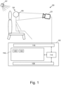
- Fig. 1 shows an example of a medical system 100.
- a camera 101 is focused on an imaging zone 105 of the subject 104.
- the camera 101 is connected to a hardware interface 116 of a computer system 102.
- the camera 101 may be configured to acquire video data from the imaging zone 105, to store the video data and transmit the video data to the computer system 102.
- the video data may, for example, be transmitted as a stream.
- the computer system 102 may control the acquisition of the video data by the camera 101.
- a light source 107 is provided in order to illuminate the subject 104 and in particular the imaging zone 105.
- the computer system 102 is provided with a processor 114.
- the computer system 102 is intended to represent one or more computers or computer systems.
- the processor 114 is intended to represent one or more computational systems or computational cores.
- the computer system 102 is further shown as containing the hardware interface 116 which is connected to the processor 114. If other components of the medical system 100 are present or included such as a magnetic resonance imaging system, then the hardware interface 116 could be used to exchange data and commands with these other components.
- the computer system 102 is further shown as comprising an optional user interface 108 which may provide various means for relaying data and receiving data and commands from an operator.
- the computer system 102 is further shown as comprising a memory 110 that is connected to the processor 114.
- the memory 110 is intended to represent various types of memory which may be accessible to the processor 114.
- the memory 110 is shown as containing machine-executable instructions 120.
- the machine-executable instructions 120 are instructions which enable the processor 114 to perform various control, data processing, and image processing tasks.
- the memory 110 is further shown as containing videos 122 acquired by the camera 101.
- the present subject matter may use the medical system 100 to perform a method such as the method of Fig. 2 in order to determine PTT of the subject 104.
- Video frames of a video which have been acquired from a subject 104 may be received in step 201.
- a PPG signal and a BCG signal may be derived or determined in step 203 from the received video frames.
- First markers may be determined or identified in step 205 in the PPG signal.
- Second markers may be determined or identified in step 207 in the BCG signal.
- a selected first marker of the first markers and/or a selected second marker of the second markers may be used in step 209 to define a trigger time for acquiring medical data from the subject.
- the method of Fig. 2 may be performed for acquisition of MRI data from the subject 104 using the determined trigger time. In one example implementation, named offline implementation, the method of Fig. 2 may be performed for measuring vital sign information of the subject 104.
- Fig. 3 is a flowchart of a method for determining a PPG signal and BCG signal in accordance with an example of the present subject matter.
- the method described in Fig. 3 may be implemented in the system illustrated in Fig. 1 , but is not limited to this implementation.
- the method may, for example, be performed by the medical system 100 or by another system that is configured to connect to the medical system 100.
- the method of Fig. 3 may provide an example implementation for obtaining the PPG signal and the BCG signal in Fig. 2 .
- Video frames of a video which have been acquired from a subject 104 may be received in step 301.
- First regions which are candidate sources of PPG information may be identified in the frames in step 303.
- a candidate PPG signal may be determined in step 305 for each first region of the first regions. This may result in a set of candidate PPG signals.
- Second regions which are candidate sources of BCG information may be identified in the frames in step 307. The second regions are provided such that they are different from the first regions.
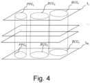
- Fig. 4 illustrate an example distribution of the identified first and second regions. It may be determined in step 309 for each second region a candidate BCG signal. This may result in a set of candidate BCG signals.
- a clustering of the candidate PPG signals and the candidate BCG signals may be performed in step 311 in order to obtain a cluster (BCG cluster) of signals representing BCG and another cluster (PPG cluster) of signals representing PPG. This may further result in a third cluster which represent signals different from both the BCG signals and PPG signals.
- the signals of the BCG cluster may be combined in step 313 for obtaining of the BCG signal.
- the signals of the PPG cluster may be combined in step 315 for obtaining the PPG signal.
- the combination may, for example, be the average.
- Fig. 4 depicts a series of M frames (or images) I 1 ...I M of a received video.
- the series of frames I 1 ...I M may be the frames received in step 201.
- Fig. 4 depicts a first region (PPG region) and two second regions (BCG regions) PPG 1 , BCG 1 and BCG 2 .
- PPG region first region
- BCG regions second regions
- the regions reappear in each frame of the frames.
- Each region has its own set of pixels.
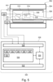
- Fig. 5 shows a further example of a medical instrument 500.
- the medical instrument 500 comprises a magnetic resonance imaging system 502.
- the magnetic resonance imaging system 502 comprises a magnet 504.
- the magnet 504 is a superconducting cylindrical type magnet with a bore 506 through it.
- the use of different types of magnets is also possible; for instance, it is also possible to use both a split cylindrical magnet and a so-called open magnet.
- a split cylindrical magnet is similar to a standard cylindrical magnet, except that the cryostat has been split into two sections to allow access to the iso-plane of the magnet, such magnets may for instance be used in conjunction with charged particle beam therapy.
- An open magnet has two magnet sections, one above the other with a space in-between that is large enough to receive a subject: the arrangement of the two sections area similar to that of a Helmholtz coil. Open magnets are popular, because the subject is less confined. Inside the cryostat of the cylindrical magnet there is a collection of superconducting coils. Within the bore 506 of the cylindrical magnet 504 there is an imaging volume 508 where the magnetic field is strong and uniform enough to perform magnetic resonance imaging. A region of interest 509 is shown within the imaging volume 508. A subject 518 is shown as being supported by a subject support 520 such that at least a portion of the subject 518 is within the imaging volume 508 and the region of interest 509.
- the magnetic field gradient coils 510 are used for acquisition of magnetic resonance data to spatially encode magnetic spins within the imaging volume 508 of the magnet 504.
- the magnetic field gradient coils 510 connected to a magnetic field gradient coil power supply 512.
- the magnetic field gradient coils 510 are intended to be representative.
- magnetic field gradient coils 510 contain three separate sets of coils for spatially encoding in three orthogonal spatial directions.
- a magnetic field gradient power supply supplies current to the magnetic field gradient coils.
- the current supplied to the magnetic field gradient coils 510 is controlled as a function of time and may be ramped or pulsed.
- a radio-frequency coil or surface coil 514 Adjacent to the imaging volume 508 is a radio-frequency coil or surface coil 514 for manipulating the orientations of magnetic spins within the imaging volume 508 and for receiving radio transmissions from spins also within the imaging volume 508.
- the radio frequency antenna may contain multiple coil elements.
- the radio frequency antenna may also be referred to as a channel or antenna.
- the radio-frequency coil 514 is connected to a radio frequency transceiver 516.
- the radio-frequency coil 514 and radio frequency transceiver 516 may be replaced by separate transmit and receive coils and a separate transmitter and receiver. It is understood that the radio-frequency coil 514 and the radio frequency transceiver 516 are representative.
- the radio-frequency coil 514 is intended to also represent a dedicated transmit antenna and a dedicated receive antenna.
- the transceiver 516 may also represent a separate transmitter and receivers.
- the radio-frequency coil 514 may also have multiple receive/transmit elements and the radio frequency transceiver 516 may have multiple receive/transmit channels. For example, if a parallel imaging technique such as SENSE is performed, the radio-frequency coil 514 will have multiple coil elements.
- a camera 501 can be seen as being mounted on the flange of the magnet 504. The face of the subject is imaged by the camera 501.
- the transceiver 516, the gradient controller 512, and camera 501 are shown as being connected to a hardware interface 528 of a computer system 526.
- the computer system further comprises a processor 530 that is in communication with the hardware system 528, a memory 534, and a user interface 532.
- the memory 534 may be any combination of memory which is accessible to the processor 530. This may include such things as main memory, cached memory, and also non-volatile memory such as flash RAM, hard drives, or other storage devices. In some examples the memory 530 may be considered to be a non-transitory computer-readable medium.
- the computer memory 534 is shown as containing machine-executable instructions 540.
- the machine-executable instructions contain commands or instructions which enable the processor 530 to control the operation and function of the magnetic resonance imaging system 502.
- the computer memory 534 is shown as further containing pulse sequence commands 542.
- the pulse sequence commands 542 are either instructions or data which may be converted into instructions which enable the processor 530 to control the magnetic resonance imaging system 502 to acquire magnetic resonance data.
- Fig. 6 is a flowchart of a method for determining a PPG signal in accordance with an example of the present subject matter.
- the method described in Fig. 6 may be implemented in the system illustrated in Fig. 1 , but is not limited to this implementation.
- the method may, for example, be performed by the medical system 100 or by another system that is configured to connect to the medical system 100.
- the method of Fig. 6 may provide an example implementation for obtaining the PPG signal in Fig. 2 .
- a PPG signal may be constructed from the video sequence.
- a first instance of the PPG signal is made.
- the time domain signals from average over patches of the image are correlated with the constructed PPG signal.
- Patches that contain BCG information are thus identified by the correlation.
- This is shown in Fig. 11 where an image 1100 is shown with a superimposed heat map of the correlation coefficients of the PPG signal and the time domain signals.
- the vertical bar indicates normalized values of the amplitude of the signal.
- the vertical bar indicates that the correlation areas are on the face and also on the chest. Patches 1101, 1103 and 1105 may be blacked-out regions which are added for restraining the identification of the subject.
Landscapes
- Health & Medical Sciences (AREA)
- Life Sciences & Earth Sciences (AREA)
- Engineering & Computer Science (AREA)
- Physics & Mathematics (AREA)
- Physiology (AREA)
- Biophysics (AREA)
- General Health & Medical Sciences (AREA)
- Cardiology (AREA)
- Animal Behavior & Ethology (AREA)
- Public Health (AREA)
- Veterinary Medicine (AREA)
- Surgery (AREA)
- Pathology (AREA)
- Molecular Biology (AREA)
- Medical Informatics (AREA)
- Heart & Thoracic Surgery (AREA)
- Biomedical Technology (AREA)
- Pulmonology (AREA)
- Signal Processing (AREA)
- Computer Vision & Pattern Recognition (AREA)
- Oral & Maxillofacial Surgery (AREA)
- Dentistry (AREA)
- Nuclear Medicine, Radiotherapy & Molecular Imaging (AREA)
- Radiology & Medical Imaging (AREA)
- General Physics & Mathematics (AREA)
- High Energy & Nuclear Physics (AREA)
- Condensed Matter Physics & Semiconductors (AREA)
- Power Engineering (AREA)
- Psychiatry (AREA)
- Artificial Intelligence (AREA)
- Magnetic Resonance Imaging Apparatus (AREA)
Priority Applications (2)
| Application Number | Priority Date | Filing Date | Title |
|---|---|---|---|
| CN202480037816.3A CN121263128A (zh) | 2023-06-07 | 2024-06-05 | 使用ppg和bcg信号来触发医学数据采集 |
| PCT/EP2024/065411 WO2024251779A1 (en) | 2023-06-07 | 2024-06-05 | Triggering medical data acquisition using ppg and bcg signals |
Applications Claiming Priority (1)
| Application Number | Priority Date | Filing Date | Title |
|---|---|---|---|
| CN2023098754 | 2023-06-07 |
Publications (1)
| Publication Number | Publication Date |
|---|---|
| EP4473901A1 true EP4473901A1 (de) | 2024-12-11 |
Family
ID=87418872
Family Applications (1)
| Application Number | Title | Priority Date | Filing Date |
|---|---|---|---|
| EP23185979.4A Withdrawn EP4473901A1 (de) | 2023-06-07 | 2023-07-18 | Auslösung der erfassung medizinischer daten unter verwendung von ppg- und bcg-signalen |
Country Status (1)
| Country | Link |
|---|---|
| EP (1) | EP4473901A1 (de) |
Citations (3)
| Publication number | Priority date | Publication date | Assignee | Title |
|---|---|---|---|---|
| US20160331239A1 (en) * | 2014-02-03 | 2016-11-17 | The Board Of Trustees Of The Leland Stanford Junior University | Contact-free physiological monitoring during simultaneous magnetic resonance imaging |
| US20170055934A1 (en) * | 2015-08-24 | 2017-03-02 | Siemens Healthcare Gmbh | Method and system for determining a trigger signal |
| US20200046300A1 (en) * | 2017-03-17 | 2020-02-13 | Koninklijke Philips N.V. | Cardiac motion signal derived from optical images |
-
2023
- 2023-07-18 EP EP23185979.4A patent/EP4473901A1/de not_active Withdrawn
Patent Citations (3)
| Publication number | Priority date | Publication date | Assignee | Title |
|---|---|---|---|---|
| US20160331239A1 (en) * | 2014-02-03 | 2016-11-17 | The Board Of Trustees Of The Leland Stanford Junior University | Contact-free physiological monitoring during simultaneous magnetic resonance imaging |
| US20170055934A1 (en) * | 2015-08-24 | 2017-03-02 | Siemens Healthcare Gmbh | Method and system for determining a trigger signal |
| US20200046300A1 (en) * | 2017-03-17 | 2020-02-13 | Koninklijke Philips N.V. | Cardiac motion signal derived from optical images |
Non-Patent Citations (2)
| Title |
|---|
| SPICHER NICOLAI ET AL: "Initial evaluation of prospective cardiac triggering using photoplethysmography signals recorded with a video camera compared to pulse oximetry and electrocardiography at 7T MRI", BIOMEDICAL ENGINEERING ONLINE, vol. 15, no. 1, 1 December 2016 (2016-12-01), XP055870617, Retrieved from the Internet <URL:https://www.researchgate.net/publication/310780429_Initial_evaluation_of_prospective_cardiac_triggering_using_photoplethysmography_signals_recorded_with_a_video_camera_compared_to_pulse_oximetry_and_electrocardiography_at_7T_MRI/fulltext/596e5619a6fdcc2416901294/Initial-evaluation-of-prospective-car> DOI: 10.1186/s12938-016-0245-3 * |
| WANG WENJIN ET AL: "Fundamentals of Camera-PPG Based Magnetic Resonance Imaging", IEEE JOURNAL OF BIOMEDICAL AND HEALTH INFORMATICS, IEEE, PISCATAWAY, NJ, USA, vol. 26, no. 9, 17 December 2021 (2021-12-17), pages 4378 - 4389, XP011919507, ISSN: 2168-2194, [retrieved on 20211220], DOI: 10.1109/JBHI.2021.3136603 * |
Similar Documents
| Publication | Publication Date | Title |
|---|---|---|
| US12042306B2 (en) | Cardiac motion signal derived from optical images | |
| EP3254130B1 (de) | Automatische gruppierung von magnetresonanzbildern | |
| US11751818B2 (en) | Method and system for creating a roadmap for a medical workflow | |
| JP2019530486A (ja) | 動き補正された圧縮検知磁気共鳴イメージング | |
| EP3913387A1 (de) | Bewegungsschätzung und -korrektur in der magnetresonanzbildgebung | |
| CN112204411A (zh) | Cest磁共振成像中的运动检测 | |
| EP4473901A1 (de) | Auslösung der erfassung medizinischer daten unter verwendung von ppg- und bcg-signalen | |
| EP3785227B1 (de) | Automatisierte objektüberwachung für medizinische bildgebung | |
| EP3769103B1 (de) | Selbstnavigation in der dreidimensionalen magnetresonanzbildgebung | |
| WO2024251779A1 (en) | Triggering medical data acquisition using ppg and bcg signals | |
| JP2026507438A (ja) | Ppg信号を模倣するフリッカの識別及び軽減 | |
| CN110114685B (zh) | 使用最大似然重建的对心脏的t1映射 | |
| EP4390433A1 (de) | Kardiovaskuläre magnetresonanzbildgebung unter verwendung von fern-fotoplethysmografie | |
| US20250228466A1 (en) | Making anatomical measurements using magnetic resonance imaging | |
| EP4303605A1 (de) | Aufnahme von mehrfach-magnetresonanzbildern mit mehrfachkontrasten bei der mehr-echo-gradientenecho-magnetresonanztomografie | |
| EP3543724A1 (de) | (3-n)-dimensionale bestimmung der elektrischen leitfähigkeit |
Legal Events
| Date | Code | Title | Description |
|---|---|---|---|
| PUAI | Public reference made under article 153(3) epc to a published international application that has entered the european phase |
Free format text: ORIGINAL CODE: 0009012 |
|
| STAA | Information on the status of an ep patent application or granted ep patent |
Free format text: STATUS: THE APPLICATION HAS BEEN PUBLISHED |
|
| AK | Designated contracting states |
Kind code of ref document: A1 Designated state(s): AL AT BE BG CH CY CZ DE DK EE ES FI FR GB GR HR HU IE IS IT LI LT LU LV MC ME MK MT NL NO PL PT RO RS SE SI SK SM TR |
|
| STAA | Information on the status of an ep patent application or granted ep patent |
Free format text: STATUS: THE APPLICATION IS DEEMED TO BE WITHDRAWN |
|
| 18D | Application deemed to be withdrawn |
Effective date: 20250612 |