EP4473851A1 - Aerosol generation device - Google Patents
Aerosol generation device Download PDFInfo
- Publication number
- EP4473851A1 EP4473851A1 EP23773857.0A EP23773857A EP4473851A1 EP 4473851 A1 EP4473851 A1 EP 4473851A1 EP 23773857 A EP23773857 A EP 23773857A EP 4473851 A1 EP4473851 A1 EP 4473851A1
- Authority
- EP
- European Patent Office
- Prior art keywords
- electrode
- generation device
- plasma generator
- aerosol
- aerosol generation
- Prior art date
- Legal status (The legal status is an assumption and is not a legal conclusion. Google has not performed a legal analysis and makes no representation as to the accuracy of the status listed.)
- Pending
Links
Images






Classifications
-
- A—HUMAN NECESSITIES
- A24—TOBACCO; CIGARS; CIGARETTES; SIMULATED SMOKING DEVICES; SMOKERS' REQUISITES
- A24F—SMOKERS' REQUISITES; MATCH BOXES; SIMULATED SMOKING DEVICES
- A24F40/00—Electrically operated smoking devices; Component parts thereof; Manufacture thereof; Maintenance or testing thereof; Charging means specially adapted therefor
- A24F40/40—Constructional details, e.g. connection of cartridges and battery parts
- A24F40/46—Shape or structure of electric heating means
-
- H—ELECTRICITY
- H05—ELECTRIC TECHNIQUES NOT OTHERWISE PROVIDED FOR
- H05H—PLASMA TECHNIQUE; PRODUCTION OF ACCELERATED ELECTRICALLY-CHARGED PARTICLES OR OF NEUTRONS; PRODUCTION OR ACCELERATION OF NEUTRAL MOLECULAR OR ATOMIC BEAMS
- H05H1/00—Generating plasma; Handling plasma
- H05H1/24—Generating plasma
- H05H1/2406—Generating plasma using dielectric barrier discharges, i.e. with a dielectric interposed between the electrodes
- H05H1/2425—Generating plasma using dielectric barrier discharges, i.e. with a dielectric interposed between the electrodes the electrodes being flush with the dielectric
-
- H—ELECTRICITY
- H05—ELECTRIC TECHNIQUES NOT OTHERWISE PROVIDED FOR
- H05H—PLASMA TECHNIQUE; PRODUCTION OF ACCELERATED ELECTRICALLY-CHARGED PARTICLES OR OF NEUTRONS; PRODUCTION OR ACCELERATION OF NEUTRAL MOLECULAR OR ATOMIC BEAMS
- H05H1/00—Generating plasma; Handling plasma
- H05H1/24—Generating plasma
- H05H1/2406—Generating plasma using dielectric barrier discharges, i.e. with a dielectric interposed between the electrodes
- H05H1/2431—Generating plasma using dielectric barrier discharges, i.e. with a dielectric interposed between the electrodes using cylindrical electrodes, e.g. rotary drums
-
- A—HUMAN NECESSITIES
- A24—TOBACCO; CIGARS; CIGARETTES; SIMULATED SMOKING DEVICES; SMOKERS' REQUISITES
- A24F—SMOKERS' REQUISITES; MATCH BOXES; SIMULATED SMOKING DEVICES
- A24F40/00—Electrically operated smoking devices; Component parts thereof; Manufacture thereof; Maintenance or testing thereof; Charging means specially adapted therefor
- A24F40/20—Devices using solid inhalable precursors
-
- A—HUMAN NECESSITIES
- A24—TOBACCO; CIGARS; CIGARETTES; SIMULATED SMOKING DEVICES; SMOKERS' REQUISITES
- A24F—SMOKERS' REQUISITES; MATCH BOXES; SIMULATED SMOKING DEVICES
- A24F40/00—Electrically operated smoking devices; Component parts thereof; Manufacture thereof; Maintenance or testing thereof; Charging means specially adapted therefor
- A24F40/40—Constructional details, e.g. connection of cartridges and battery parts
-
- A—HUMAN NECESSITIES
- A24—TOBACCO; CIGARS; CIGARETTES; SIMULATED SMOKING DEVICES; SMOKERS' REQUISITES
- A24F—SMOKERS' REQUISITES; MATCH BOXES; SIMULATED SMOKING DEVICES
- A24F40/00—Electrically operated smoking devices; Component parts thereof; Manufacture thereof; Maintenance or testing thereof; Charging means specially adapted therefor
- A24F40/40—Constructional details, e.g. connection of cartridges and battery parts
- A24F40/48—Fluid transfer means, e.g. pumps
- A24F40/485—Valves; Apertures
-
- A—HUMAN NECESSITIES
- A24—TOBACCO; CIGARS; CIGARETTES; SIMULATED SMOKING DEVICES; SMOKERS' REQUISITES
- A24F—SMOKERS' REQUISITES; MATCH BOXES; SIMULATED SMOKING DEVICES
- A24F40/00—Electrically operated smoking devices; Component parts thereof; Manufacture thereof; Maintenance or testing thereof; Charging means specially adapted therefor
- A24F40/50—Control or monitoring
- A24F40/57—Temperature control
Definitions
- Tobacco products (such as cigarettes and cigars) are used by burning tobacco to produce tobacco smoke. Attempts are made to replace these tobacco-burning products by manufacturing products that release compounds without burning.
- an example of this type of products is a heating device that releases compounds by heating rather than burning materials.
- the materials may be an aerosol-generating product including tobacco or other non-tobacco products, where these non-tobacco products may or may not include nicotine.
- an existing heating device usually heats the aerosol-generating product by using a resistance heating element or an electromagnetic induction heating element.
- An embodiment of this application provides an aerosol generation device, configured to heat an aerosol-generating product to generate an aerosol, including:
- a plasma generator configured to generate plasma to heat the aerosol-generating product through the plasma.
- the plasma is constructed to be generated by applying a breakdown voltage to a gas to break the gas down.
- the gas includes at least one of air, helium, and neon.
- an electron number density of the plasma generated by the plasma generator is 10 10 /cm 3 -10 13 /cm 3 .
- the plasma generated by the plasma generator further includes two or more of oxygen atoms, excited-state nitrogen molecules, ozone molecules, hydroxyl groups, oxygen ions, nitrogen ions, and nitrogen oxide molecules.
- the plasma generator is based on atmospheric-pressure glow discharge.
- the plasma generated by the plasma generator is non-equilibrium plasma.
- the plasma generator is provided based on dielectric barrier discharge.
- the plasma generator is provided based on micro hollow cathode discharge.
- the plasma generator is configured with:
- the inlet and the outlet are staggered relative to each other in an axial direction of the plasma generator.
- no obstacle that blocks the plasma exists between the outlet and the aerosol-generating product.
- the plasma generator includes a first electrode and a second electrode that are spaced apart, to form a breakdown field between the first electrode and the second electrode to break the gas down to generate the plasma.
- the breakdown field is 10-50 kV/cm.
- the first electrode and the second electrode are arranged substantially in parallel.
- the first electrode and/or the second electrode are/is in a shape of a sheet or plate or ring or tube.
- the first electrode and/or the second electrode are/is rigid.
- the first electrode and/or the second electrode are/is thin.
- the first electrode and/or the second electrode have/has a length, a width, and a thickness; and the thickness of the first electrode and/or the second electrode is less than the length and the width.
- the first electrode and/or the second electrode have/has a thickness of 0.05-0.5 mm.
- the first electrode and/or the second electrode have/has the same shape or size.
- the first electrode and/or the second electrode have/has resistivity of about 1 ⁇ 10 -5 -1 ⁇ 10 -9 ⁇ m.
- the first electrode and/or the second electrode include/includes copper, gold, silver, platinum, or an alloy thereof.
- the breakdown field is intermittent or pulsed.
- the plasma generator further includes: a dielectric, at least partially located between the first electrode and the second electrode, for inhibiting discharge-to-arc transition between the first electrode and the second electrode.
- the dielectric is arranged to be a coating or film layer formed on a surface of the first electrode and/or the second electrode.
- a dielectric constant of the dielectric is greater than 5.
- the dielectric includes at least one of aluminum oxide, zirconium oxide, ceramic, glass, quartz, and an organic polymer.
- the plasma generator has a fluid channel running through the plasma generator; and the fluid channel at least partially extends in the dielectric; or the fluid channel is at least partially formed between the dielectric and the first electrode; or the fluid channel is at least partially formed between the dielectric and the second electrode.
- one of the first electrode and the second electrode is located inside the dielectric, and the other is located outside the dielectric.
- the aerosol generation device further includes: a substrate, arranged to emit heat by receiving at least partial plasma from the plasma generator, to heat the aerosol-generating product.
- the substrate at least partially defines a cavity for receiving the aerosol-generating product.
- the substrate includes a metal or an alloy.
- thermal conductivity of the substrate is greater than 40 W/mK.
- the substrate is arranged to be not in contact with the plasma generator; and/or the substrate is arranged to be in contact with the aerosol-generating product.
- the plasma generator is arranged to at least partially surround the substrate.
- the substrate is provided with a hole, and at least partial plasma from the plasma generator is outputted to the aerosol-generating product through the hole.
- the plasma generator is provided with a high-voltage pulse power supply.
- the aerosol generation device further includes:
- a direct-current voltage, an alternating-current voltage, a radio-frequency voltage, or the like is provided to the plasma generator, and then an electric field is generated through the excitation by the direct-current voltage, the alternating-current voltage, the radio-frequency voltage, or the like, to break a gas down to generate plasma.
- the plasma generator is excited by a direct-current voltage, an alternating-current voltage, or a radio-frequency voltage to generate an electric field to break a gas down to generate plasma.
- frequency of the impulse voltage is 1-100 kHz.
- a voltage amplitude of the impulse voltage is 1-9 kV.
- an impulse width of the impulse voltage is 10-600 ns.
- the impulse voltage is obtained by boosting an output voltage of the cell at least twice.
- the circuit board includes:
- the plasma generator is constructed to extend substantially in a longitudinal direction of the aerosol generation device.
- the plasma generator is constructed to be substantially perpendicular to a longitudinal direction of the aerosol generation device.
- the aerosol generation device further includes:
- the aerosol generation device further includes:
- the aerosol generation device further includes:
- the plasma generator has a fluid channel running through the plasma generator.
- the fluid channel substantially extends straight.
- the fluid channel is constructed to run through the plasma generator in an axial direction.
- the fluid channel has an inner diameter of 0.1-0.9 mm.
- the plasma generator further includes: a first conducting element and a second conducting element for supplying power to the plasma generator, where
- the first conducting element is further arranged to at least partially provide support to the first electrode; and/or the second conducting element is further arranged to at least partially provide support to the second electrode.
- the first conducting element and/or the second conducting element are/is constructed to be in a shape of a ring or tube.
- the first conducting element and the second conducting element are arranged coaxially.
- the first electrode and/or the first conducting element are/is located in the second conducting element.
- the plasma generator further includes:
- the plasma generator further includes: an outer cover, at least partially defining an outer surface of the plasma generator, and making the surface of the plasma generator electrically insulated.
- the outer cover is further arranged to accommodate and hold the first electrode and the second electrode.
- the plasma generator further includes:
- the plasma generator is constructed to output the plasma in a longitudinal direction of the plasma generator.
- the aerosol generation device further includes:
- the plasma generator includes at least: a first plasma generator and a second plasma generator, configured to independently output the plasma to different parts of the aerosol-generating product, to independently heat the different parts of the aerosol-generating product.
- the first plasma generator and the second plasma generator are configured to heat the different parts of the aerosol-generating product one after the other.
- the plasma generator includes at least: a first plasma generator and a second plasma generator, configured to heat different parts of the aerosol-generating product according to different preset temperatures, to heat the different parts of the aerosol-generating product to the different temperatures.
- the plasma generator includes at least:
- the mechanical isolator is insulated and is configured to provide insulation between the adjacent first plasma generator and second plasma generator.
- the mechanical isolator is in a shape of a ring or tube.
- the aerosol generation device further includes:
- Another embodiment of this application further provides an aerosol generation device, configured to heat an aerosol-generating product to generate an aerosol, including:
- the substrate at least partially defines a cavity for receiving the aerosol-generating product.
- Another embodiment of this application further provides an aerosol generation device, configured to heat an aerosol-generating product to generate an aerosol, including: a first plasma generator and a second plasma generator that are spaced apart in a longitudinal direction, configured to output plasma to different parts of the aerosol-generating product one after the other, to sequentially heat the different parts of the aerosol-generating product.
- an aerosol generation device configured to heat an aerosol-generating product to generate an aerosol, including: a first plasma generator and a second plasma generator that are spaced apart in a longitudinal direction, configured to output plasma to different parts of the aerosol-generating product one after the other, to sequentially heat the different parts of the aerosol-generating product.
- Another embodiment of this application further provides an aerosol generation device, configured to heat an aerosol-generating product to generate an aerosol, including:
- the plasma generator provides the plasma to the aerosol-generating product to heat the aerosol-generating product.
- the capillary element includes a porous body, a porous fiber, a capillary tube, and the like.
- Another embodiment of this application further provides an aerosol generation device, configured to heat an aerosol-generating product to generate an aerosol, including an outer shell, where the outer shell is configured with:
- the plasma generator is spaced apart from the cavity in a longitudinal direction of the outer shell, and is constructed to output the plasma in the longitudinal direction of the outer shell to the aerosol-generating product received in the cavity.
- the air channel extends straight.
- the air channel has an extended length of 10-30 mm; or a distance between the plasma generator and the cavity is 10-30 mm.
- a spacing distance between the first electrode and the second electrode is 10-2000 ⁇ m.
- the first electrode and the second electrode are substantially planar and are arranged perpendicular to the longitudinal direction of the outer shell.
- the first electrode and/or the second electrode have/has a thickness of 0.05-0.5 mm.
- a dielectric constant of the dielectric is greater than 5.
- one of the first electrode and the second electrode is located inside the dielectric, and the other is located outside the dielectric.
- the first conducting element is further arranged to at least partially provide support to the first electrode; and/or the second conducting element is further arranged to at least partially provide support to the second electrode.
- the first conducting element and/or the second conducting element are/is constructed to be in a shape of a ring or tube.
- the first conducting element and the second conducting element are arranged coaxially.
- the first electrode and/or the first conducting element are/is located in the second conducting element.
- the outlet and the inlet of the plasma generator are provided opposite to each other in the longitudinal direction.
- the plasma generator further includes a fluid channel extending between the inlet and the outlet; and the fluid channel is at least partially located between the first electrode and the second electrode.
- the plasma generator further includes: an outer cover, at least partially defining an outer surface of the plasma generator, and making the surface of the plasma generator electrically insulated.
- the outer cover is further arranged to accommodate and hold the first electrode and the second electrode.
- the plasma generator further includes:
- the aerosol generation device further includes:
- the inlet includes one or more holes formed on one of the first electrode and the second electrode; and/or the outlet includes one or more holes formed on the other of the first electrode and the second electrode.
- the power supply component is configured to provide an impulse voltage; and the first electrode and the second electrode are configured to form a breakdown field when excited by the impulse voltage, to break a gas down to generate the plasma.
- the plasma generator may be further excited by a direct-current voltage, an alternating-current voltage, a radio-frequency voltage, or the like to generate an electric field to break a gas down to generate plasma.
- the power supply component includes:
- Another embodiment of this application further provides a plasma generator for an aerosol generation device, including:
- Another embodiment of this application further provides an aerosol generation device, configured to heat an aerosol-generating product to generate an aerosol, including:
- An embodiment of the present invention provides an aerosol generation device that heats but not burns an aerosol-generating product 1000, for example, a cigarette, to volatilize or release at least one of components of the aerosol-generating product 1000 to form an aerosol for inhalation.
- the aerosol-generating product 1000 is preferably made of a tobacco-containing material that releases a volatile compound from a substrate when being heated, or may be made of a non-tobacco material suitable for releasing smoke through electrical heating after being heated.
- the aerosol-generating product 1000 preferably uses a solid substrate, which may include one or more of powders, particles, fragmented strips, strips, or flakes of one or more of vanilla leaves, tobacco leaves, homogeneous tobacco, and expanded tobacco.
- the solid substrate may include additional tobacco or non-tobacco volatile aroma compounds to be released when the substrate is heated.
- an aerosol generation device generates plasma and heats the aerosol-generating product 1000 using the plasma.
- FIG. 1 and FIG. 2 A configuration of an aerosol generation device according to an embodiment of the present invention may be shown in FIG. 1 and FIG. 2 .
- the overall shape of the device is roughly configured into a flat cylinder shape, and an external member of the aerosol generation device 100 includes: a housing 10, having a hollow structure inside, to form an assembly space for a component with a necessary function, for example, plasma generation, where the housing 10 has a proximal end 110 and a distal end 120 opposite to each other in a length direction.
- the proximal end 110 is provided with an opening 111, and the aerosol-generating product 1000 may be received in the housing 10 through the opening 111 to be heated or removed from the housing 10.
- the distal end 120 is provided with an air inlet 121, where the air inlet 121 is provided to supply outside air into the housing 10 during inhalation; and a charging interface 122, such as a USB type-C interface or a pin interface, for charging the aerosol generation device after being connected to an external power supply or an adapter.
- a charging interface 122 such as a USB type-C interface or a pin interface
- the aerosol generation device 100 further includes:
- the aerosol generation device 100 further includes: a plasma generator 20, configured to generate plasma and heat, using the plasma, the aerosol-generating product 1000 received in the cavity 170.
- the physical term "plasma” is a mixture of electrons, ions, atoms, and atomic groups generated through the ionization of gas molecules when an applied voltage reaches a breakdown voltage.
- the plasma generator 20 is a generator that generates plasma by applying a breakdown voltage on a gas to discharge to break the gas down.
- the physical term “breakdown” indicates that a dielectric loses its dielectric property and becomes a conductor under the action of a sufficiently strong electric field; and a voltage that "breaks down” the dielectric is the "breakdown voltage”.
- the "plasma” may be divided based on particle temperatures into equilibrium plasma (where an electron temperature is essentially equal to an ion temperature) and non-equilibrium plasma (where an electron temperature is much higher than an ion temperature).
- the plasma generated by the plasma generator 20 is non-equilibrium plasma.
- the physical term "non-equilibrium plasma” is low-temperature plasma with a low degree of ionization, where the electron temperature is much higher than the ion temperature.
- the plasma generator 20 is based on atmospheric-pressure glow discharge (APGD).
- APGD atmospheric-pressure glow discharge
- the plasma generator 20 based on atmospheric-pressure glow discharge operates in an open environment with an operating gas of air at atmospheric pressure.
- the plasma generator 20 is a generator that generates plasma by discharging to break air down.
- the plasma generator 20 includes:
- the plasma can be directly emitted or outputted or applied to the aerosol-generating product 1000.
- one part of the plasma can directly transfer thermal energy from the plasma gas to the aerosol-generating product 1000 for heating; and the other part of the plasma enables active particles (electrons, ions, free radicals, and the like) to undergo a series of physicochemical reactions with the aerosol-generating product 1000 to heat the aerosol-generating product 1000.
- airflow channels are formed in the aerosol generation device 100 between the air inlet 121 and the opening 111, to jointly define an airflow path from the air inlet 121 to the opening 111 or the cavity 170 through the plasma generator 20.
- at least some of the airflow channels run through the plasma generator 20.
- at least some of the airflow channels are located in the plasma generator 20.
- the plasma generator 20 is at least partially exposed to the airflow channels.
- the aerosol generation device 100 further includes: a gas source 30, configured to provide the plasma generator 20 with a gas that can generate plasma by discharge breakdown.
- the gas stored in the gas source 30 and provided to the plasma generator 20 is helium, neon, or the like that is more stable than plasma generated by air breakdown.
- the gas source 30 provides the gas to the plasma generator 20 through the air channel 150 along an arrow R12.
- FIG. 2 is a schematic diagram of the plasma generator 20 according to an embodiment.
- the plasma generator 20 includes: a first electrode 21 and a second electrode 22 that are spaced apart, to form an electric field therebetween for discharging to break down air or the gas from the gas source 30.
- a breakdown field formed between the first electrode 21 and the second electrode 22 is about 10-50 kV/cm; more preferably, the breakdown field formed between the first electrode 21 and the second electrode 22 is about 20-40 kV/cm; and more preferably, the breakdown field formed between the first electrode 21 and the second electrode 22 is 28-32 kV/cm.
- the plasma generator 20 is based on micro hollow cathode discharge (MHCD) excited by high-voltage pulses; and in use, the high-voltage pulses are provided to the plasma generator 20, specifically to the first electrode 21 and the second electrode 22, for the plasma generator 20 to generate a pulsed electric field to generate plasma.
- MHCD micro hollow cathode discharge
- the first electrode 21 and the second electrode 22 are arranged substantially in parallel; and a spacing distance between the first electrode 21 and the second electrode 22 is greater than 10 ⁇ m and less than 2000 ⁇ m. More preferably, the spacing distance between the first electrode 21 and the second electrode 22 is 500-1500 ⁇ m; and more preferably, the spacing distance between the first electrode 21 and the second electrode 22 is 800-1200. The spacing distance between the first electrode 21 and the second electrode 22 cannot be less than 5 ⁇ m.
- the first electrode 21 and/or the second electrode 22 are/is a plate electrode, a coaxially arranged ring electrode, or the like.
- the first electrode 21 and/or the second electrode 22 are/is thin. Further, the first electrode 21 and/or the second electrode 22 are/is in a shape of a thin sheet or plate. Alternatively, the first electrode 21 and/or the second electrode 22 have/has a length, a width, and a thickness; and the thickness of the first electrode 21 and/or the second electrode 22 is less than the length and the width.
- the first electrode 21 and/or the second electrode 22 have/has a thickness of about 0.05-0.5 mm; and more preferably, the first electrode 21 and/or the second electrode 22 have/has a thickness of about 0.1-0.3 mm.
- a distance between the first electrode 21 and/or the second electrode 22 is 0.1-0.8 mm; more preferably, the distance between the first electrode 21 and/or the second electrode 22 is 0.2-0.6 mm; and more preferably, the distance between the first electrode 21 and/or the second electrode 22 is 0.4-0.5 mm.
- first electrode 21 and/or the second electrode 22 are/is round or rectangular or curved or bowed or ring-shaped.
- the first electrode 21 and/or the second electrode 22 are/is rigid.
- the material term “rigidity” is opposed to “flexibility”. Usually, the "rigidity” is the property of a material or object to be hard and not easily deformed, and is usually measured by using a physical parameter such as stiffness or modulus of elasticity.
- the first electrode 21 and/or the second electrode 22 are/is arranged in parallel.
- the first electrode 21 and/or the second electrode 22 may have the same shape or size.
- first electrode 21 and/or the second electrode 22 are/is usually made of a low-resistivity material such as copper, gold, silver, platinum, or an alloy thereof.
- the first electrode 21 and/or the second electrode 22 have/has resistivity of about 1 ⁇ 10 -5 -1 ⁇ 10 -9 ⁇ m.
- the first electrode 21 and the second electrode 22 in the plasma generator 20 are respectively connected to the circuit board 140 through wires.
- an electrically insulating dielectric is deposited, sprayed, or formed on a surface of the first electrode 21 facing the second electrode 22 and/or a surface of the second electrode 22 facing the first electrode 21.
- the plasma generator 20 further includes: at least one electrically insulating dielectric 23, which facilitates inhibiting discharge-to-arc transition, and maintaining discharge stability and uniformity.
- the dielectric is made of a material with a dielectric constant much greater than that of air.
- the dielectric may be selected from at least one of aluminum oxide, zirconium oxide, ceramic, glass, quartz, and an organic polymer such as polytetrafluoroethylene (PTFE) with the dielectric constant greater than or even much greater than that of air.
- PTFE polytetrafluoroethylene
- a dielectric constant of the dielectric is greater than 5; and more preferably, the dielectric constant of the dielectric is greater than 10.
- the dielectric 23 is also in a shape of a thin sheet or plate.
- the dielectric 23 has a thickness of about 0.1-0.8 mm; more preferably, the dielectric 23 has a thickness of about 0.2-0.6 mm; and more preferably, the dielectric 23 has a thickness of about 0.4-0.5 mm.
- the plasma generator 20 in this embodiment includes: a fluid channel 24 extending between the inlet 210 and the outlet 220, for air to enter and for outputting plasma.
- the fluid channel 24 extends straight; and the fluid channel 24 is perpendicular to a thickness direction of the plasma generator 20.
- the inlet 210 is formed on the first electrode 21; and the outlet 220 is formed on the second electrode 22.
- the fluid channel 24 has an inner diameter of about 0.1-0.9 mm.
- the fluid channel 24 has an inner diameter of about 0.2-0.8 mm.
- the fluid channel 24 has an inner diameter of about 0.4-0.6 mm.
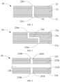
- FIG. 3 is a schematic diagram of the plasma generator 20 according to another embodiment.
- the plasma generator 20 includes:
- the fluid channel 24a at least partially extends parallel to the first electrode 21a and/or the second electrode 22a. In addition, the fluid channel 24a at least partially extends in the dielectric 23a.
- FIG. 4 is a schematic diagram of the plasma generator 20 according to another embodiment.
- the plasma generator 20 includes:
- a distance space 25b is kept between the first dielectric or coating 231b and the second dielectric or coating 232b.
- the distance space 25b is sealed in a circumferential direction.
- the plasma generator 20 further includes: an inlet 210b provided on the first electrode 21b and an outlet 220b provided on the second electrode 22b; and a fluid channel 241b extending from the inlet 210b to the distance space 25b and a fluid channel 242b extending from the distance space 25b to the outlet 220b.
- FIG. 5 is a schematic diagram of the plasma generator 20 according to another varying embodiment.
- the plasma generator 20 includes:
- FIG. 6 is a schematic diagram of the plasma generator 20 according to another varying embodiment.
- the plasma generator 20 includes:
- FIG. 7 is a schematic diagram of the plasma generator 20 according to another varying embodiment.
- the plasma generator 20 includes: a first electrode 21e and a second electrode 22e that extend in a longitudinal direction, where the first electrode 21e is in a shape of a tube surrounding the second electrode 22e; and the second electrode 22e is in a shape of a column extending in the longitudinal direction, or the like.
- the first electrode 21e and the second electrode 22e are spaced apart; and a ring-shaped dielectric 23e surrounding the second electrode 22e exists between the first electrode 21e and the second electrode 22e.
- a fluid channel 24e is defined and formed between the dielectric 23e and the first electrode 21e or between the dielectric 23e and the second electrode 22e; and the fluid channel 24e has an inlet 210e and an outlet 220e that are opposite to each other in the longitudinal direction.
- FIG. 8 is a schematic diagram of the plasma generator 20 according to another varying embodiment.
- the plasma generator 20 includes:
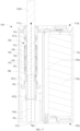
- FIG. 9 is a schematic diagram of the aerosol generation device 100 according to another specific embodiment.
- the aerosol generation device 100 includes:
- a heating structure of the aerosol generation device 100 in FIG. 9 includes:
- outside air enters from the air inlet 121 along an arrow R11 in FIG. 9 to the plasma generator 20, and forms plasma through discharge breakdown. Then, the plasma is transferred or outputted along an arrow R2 to the aerosol-generating product 1000 for heating.
- the plasma generator 20 outputs the plasma in the longitudinal direction.
- FIG. 10 to FIG. 14 are schematic diagrams of the assembly and disassembly of components of the plasma generator 20 in FIG. 9 .
- the plasma generator 20 substantially extends in the longitudinal direction of the aerosol generation device 100, and is constructed to be in a longitudinally extending cylindrical shape.
- An external member of the plasma generator 20 includes: an outer cover 28 and an end cap 29, defining an outer surface of the plasma generator 20, and configured to encapsulate functional components of the plasma generator 20 inside, where the outer cover 28 is located at an upper end of the plasma generator 20 in the longitudinal direction, and the end cap 29 is located at a lower end.
- the outer cover 28 is substantially of a tubular or cylindrical structure, and includes a section 281 and a section 282 that are arranged sequentially from the upper end to the lower end.
- a length of the section 281 is less than a length of the section 282, and an outer diameter of the section 281 is less than an outer diameter of the section 282, so that the section 281 and the section 282 form a step located on an outer surface of the outer cover 28. In assembly, the step is configured to reach into and against the lower support 42 for assembly and stopping.
- the end cap 29 includes a section 291 and a section 292.
- An outer diameter of the section 291 is less than that of the section 292.
- the section 291 extends into the section 282 of the outer cover 28, and the section 292 abuts against the lower end of the outer cover 28 for stopping.
- the outer cover 28 and the end cap 29 are made of insulating ceramic or an organic polymer such as polytetrafluoroethylene, for electrical insulation and thermal insulation.
- the outer cover 28 of the plasma generator 20 further includes:
- the end part 2310 is arranged between the first electrode 21 and the second electrode 22, to inhibit discharge-to-arc transition between the first electrode 21 and the second electrode 22; and A lower end of the peripheral part 2320 abuts against the section 291 of the end cap 29 for stopping.
- the outer cover 28 of the plasma generator 20 further includes:
- the first conducting element 26 and/or the second conducting element 27 are/is made of a low-resistivity conductor material respectively for facilitating power supply to the first electrode 21 and the second electrode 22.
- the plasma generator 20 further includes:
- an impulse voltage can be provided to the first electrode 21 and the second electrode 22 through the first conducting lead 251 and the second conducting lead 252, so that an electric field that breaks down the air or gas to generate plasma is generated between the first electrode 21 and the second electrode 22.
- a direct-current voltage, an alternating-current voltage, or a radio-frequency voltage can be provided to the first electrode 21 and the second electrode 22 through the first conducting lead 251 and the second conducting lead 252, so that an electric field that breaks down the air or gas to generate plasma is generated between the first electrode 21 and the second electrode 22.
- a notch 284 is provided at the lower end of the outer cover 28.
- the first conducting lead 251 passes through the notch 284 into the outer cover 28 to be connected to the first conducting element 26; and the second conducting lead 252 extends through the notch 284 into the outer cover 28 to be connected to the second conducting element 27.
- the section 281 of the outer cover 28 has the inner diameter of the section 282, so that a step is formed therebetween on an inner wall of the outer cover 28; and a surface of the second electrode 22 facing away from the second conducting element 27 abuts against the step on the inner wall of the outer cover 28.
- the first electrode 21, the second electrode 22, the dielectric 23, the first conducting element 26, and the second conducting element 27 are all located in the section 282 of the outer cover 28, and are avoided from the section 281 of the outer cover 28.
- the design of the fluid channel of the plasma generator 20 includes the following parts arranged sequentially in the longitudinal direction of the plasma generator 20:
- the foregoing parts are connected sequentially to form the fluid channel of the plasma generator 20, for air to enter between the first electrode 21 and the second electrode 22 to generate plasma through discharge breakdown, and then the plasma is transferred or outputted.
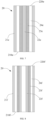
- FIG. 15 is a schematic diagram of a first electrode 21g with one hole 210g and a second electrode 22g with one hole 220g according to another embodiment.
- FIG. 16 is a schematic diagram of a first electrode 21h with multiple holes 210h and a second electrode 22h with multiple holes 220h according to another embodiment.
- the hole 210 on the first electrode 21, the hole 2311 on the end part 2310 of the dielectric 23, and the hole 220 on the second electrode 22 are aligned in the longitudinal direction of the plasma generator 20.
- the foregoing holes are at least partially staggered, for example, as shown in FIG. 16 , the holes 210h on the first electrode 21h and the holes 220h on the second electrode 22h that are at least partially staggered.
- the first electrode 21 and the second electrode 22 are round.
- the first electrode 21 and the second electrode 22 are in a rectangular, polygonal, or regular or non-regular geometrical shape.
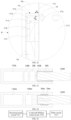
- FIG. 17 is a schematic diagram of the aerosol generation device 100 according to another specific embodiment.
- the aerosol generation device 100 includes:
- a heating structure of the aerosol generation device 100 in FIG. 17 includes: a plasma heating mechanism 60j, constructed to be in a shape of a tube or cylinder extending in the longitudinal direction of the outer shell 10j. A cavity extending in the longitudinal direction is defined in the plasma heating mechanism 60j, to accommodate and receive the aerosol-generating product 1000.
- the plasma heating mechanism 60j surrounds the aerosol-generating product 1000 and emits or transfers plasma from the periphery to the aerosol-generating product 1000 for heating.
- a sealing element 411j such as a silicone ring or a silicone sleeve is located between the upper support 41j and the plasma heating mechanism 60j for sealing therebetween;
- an air channel 150j in the support wall 43j and a hole in the lower support 42j define and form an airflow channel extending from the air inlet 121j to the plasma heating mechanism 60j.
- the plasma heating mechanism 60j specifically includes the following components:
- the first plasma generator 61j, the second plasma generator 62j, and the third plasma generator 63j sequentially start heating, that is, start heating one after the other.
- the first plasma generator 61j, the second plasma generator 62j, and the third plasma generator 63j respectively heat different parts of the aerosol-generating product 1000 according to different target or preset temperatures, to heat the different parts of the aerosol-generating product 1000 to the different temperatures.
- the plasma heating mechanism 60j further includes: at least one mechanical isolator, disposed between two adjacent plasma generators.
- the at least one mechanical isolator is arranged to provide support to the adjacent plasma generators.
- the at least one mechanical isolator is arranged to keep a distance between the adjacent plasma generators.
- the at least one mechanical isolator is an insulator or an insulating material, and then is further arranged for providing insulation between the adjacent plasma generators in the longitudinal direction.
- the plasma heating mechanism 60j includes a mechanical isolator 64j and a mechanical isolator 65j that are spaced apart sequentially in the longitudinal direction.
- the mechanical isolator 64j is arranged between the first plasma generator 61j and the second plasma generator 62j in the longitudinal direction.
- the mechanical isolator 65j is arranged between the second plasma generator 62j and the third plasma generator 63j in the longitudinal direction.
- the mechanical isolator 64j and the mechanical isolator 65j are in a shape of a ring or tube.
- the plasma heating mechanism 60j further includes: an outer cover 66j and an end cap 68j, defining an outer surface of the plasma heating mechanism 60j, and surrounding, accommodating, and holding the plasma generator and the mechanical isolator.
- the outer cover 66j and the end cap 68j wrap the plasma generator from the outside, and provide external electrical insulation and thermal insulation.
- the outer cover 66j and the end cap 68j are preferably made of an insulating organic polymer, such as polycarbonate, polytetrafluoroethylene, or polypropylene.
- the outer cover 66j includes an endwall 661j at an upper end and a peripheral wall 662j extending from the endwall 661j. In assembly, the peripheral wall 662j abuts against the end cap 68j for stopping. The endwall 661j of the outer cover 66j blocks and fastens the plasma generator from the upper end.
- the plasma generator 61j/62j/63j is in a ring shape.
- a structure of the first plasma generator 61j includes:
- a first conducting lead 616j is connected to the first conducting element 614j by soldering or the like, and is then connected to the circuit board 140j; and a second conducting lead 617j is connected to the second conducting element 615j by soldering or the like, and is then connected to the circuit board 140j.
- an impulse voltage can be provided to the first electrode 611j and the second electrode 612j through the first conducting lead 616j and the second conducting lead 617j, so that an electric field that breaks down the air or gas to generate plasma is generated between the first electrode 611j and the second electrode 612j.
- the outer cover 66j and/or the end cap 68j are/is provided with a notch or window or hole or the like, for the first conducting lead 616j and the second conducting lead 617j to extend from the outer cover 66j and/or the end cap 68j to the outside, to facilitate connection to the circuit board 140j.
- the substrate 67j is not in contact with the first plasma generator 61j/62j/63j.
- a gap d3 is kept between the substrate 67j and the first plasma generator 61j, and the gap d3 is less than 1 mm, about 0.3-0.8 mm.
- the first plasma generator 61j is kept insulated from the substrate 67j through the gap d3.
- the gap d3 between the first plasma generator 61j and the substrate 67j is filled with air as an operating gas for discharge breakdown by the first plasma generator 61j.
- the size of the gap d3 is substantially close to that of a gap d4 between the first electrode 611j and the second electrode 612j.
- the size of the gap d3 is about 0.6-1.5 times that of the gap d4.
- the substrate 67j is provided with a radially through hole 672j/673j/674j, for at least partial plasma generated by the plasma generator 61j/62j/63j to passes through the hole 672j/673j/674j to be directly provided to the aerosol-generating product 1000 in the cavity 671j for heating.
- the hole 672j is opposite to or aligned with the gap d4 between the first electrode 611j and the second electrode 612j in the radial direction, which facilitates increasing plasma transfer efficiency.
- the substrate that blocks or obscures plasma on plasma transfer and emission paths between the plasma generator and the aerosol-generating product 1000.
- the substrate is preferably made of a metal or an alloy with high thermal conductivity, such as silver, copper, aluminum, or an alloy thereof.
- the plasma generator emits and provides plasma to the substrate to heat the substrate, and then the heated substrate heats the aerosol-generating product 1000 in contact with the substrate to generate an aerosol.
- the substrate 67j for indirectly heating the aerosol-generating product 1000 has thermal conductivity greater than 40 W/mK, such as stainless steel with thermal conductivity of 58.6-41.9 W/mK, an aluminum alloy with thermal conductivity of 121-151 W/mK, and brass or pure copper with thermal conductivity greater than 100 W/mK.
- the hole 672j/673j/674j of the substrate 67j can be further provided for plasma to pass through and then directly heat the aerosol-generating product.
- the plasma can partially be directly outputted to the aerosol-generating product 1000 for direct heating, and partially be outputted to the substrate 67j to indirectly heat the aerosol-generating product 1000, which is conducive to heat homogenization.
- the substrate 67j is constructed to be in a shape of a tube without a hole on a tube wall, so that an outer surface of the substrate 67j is closed in a length direction, and then the outer surface of the substrate 67j receives the plasma emitted by the plasma generator 61j/62j/63j to emit heat and then receives the aerosol-generating product 1000 inside.
- the plasma generator heats the substrate to indirectly heat aerosol-generating product 1000; and the substrate may be in any shape or of any structure.
- the aerosol generation device further includes: a heating element, to heat the aerosol-generating product outside the plasma generator.
- FIG. 23 is a schematic diagram of an aerosol generation device according to an embodiment.
- the aerosol generation device includes:
- the aerosol generation device further includes a channel 160k between the plasma generator 20k and the aerosol-generating product 1000 in the longitudinal direction, to transfer plasma.
- the heating element 80k is a resistance heating element based on Joule heating, or an electromagnetic induction heating element that emits heat by being penetrated by a varying magnetic field, or an infrared heating element that heats the aerosol-generating product 1000 by radiating an infrared ray, or a microwave emitting element that heats the aerosol-generating product 1000 by emitting microwaves.
- FIG. 24 is a schematic diagram of an aerosol generation device according to another varying embodiment.
- the aerosol generation device includes:
- FIG. 29 is a schematic diagram of a plasma generator 20n according to another varying embodiment.
- the plasma generator 20n includes:
- Each second electrode 22n corresponds to a part of the first electrode 21n in a longitudinal direction.
- the first electrode 21n is connected to a positive output end of the circuit board 140 through a wire
- each of the multiple or several second electrodes 22n is connected to a negative end of the circuit board 140 through a wire.
- an impulse voltage is provided to the electrodes
- multiple or several breakdown fields are formed between the first electrode and the second electrodes, to break down air to generate plasma.
- a direct-current voltage, an alternating-current voltage, a radio-frequency voltage, or the like is provided to the plasma generator 20n, for the plasma generator 20n to generate an electric field to break the air or gas down to generate plasma.
- the first electrode 21n and/or the second electrode 22n are/is provided with holes to form inlets for air to enter or outlets for outputting plasma.
- the multiple or several second electrodes 22n are connected in sequence.
- the multiple or several second electrodes 22n are arranged in a matrix or array.
- a dielectric is provided between the first electrode 21n and the second electrode 22n, and/or a dielectric coating is formed on surfaces of the first electrode 21n and the second electrode 22n.
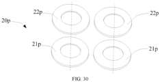
- FIG. 30 is a schematic diagram of a plasma generator 20p according to another varying embodiment.
- the plasma generator 20p includes:
- One of the multiple first electrodes 21p corresponds to one of the multiple second electrodes 22p, to form multiple electrode pairs that form breakdown fields.
- the multiple first electrodes 21p and the multiple second electrodes 22p may be arranged in an array or in a matrix, or arranged dispersedly.
- one of the first electrodes can correspond to one or more of the second electrodes, to form one or more electrode pairs; or one of the second electrodes corresponds to one or more of the first electrodes, to form one or more electrode pairs.
- the circuit board 140 controls the plasma generator 20 to provide a high-frequency and high-voltage impulse voltage to the first electrode 21 and the second electrode 22, for the plasma generator 20 to generate non-equilibrium plasma through atmospheric-pressure glow discharge.
- frequency of the impulse voltage provided to the first electrode 21 and the second electrode 22 is 1-100 kHz; preferably, the frequency of the impulse voltage is 5-50 kHz; and more preferably, the frequency of the impulse voltage is 10-20 kHz.
- a voltage amplitude of the impulse voltage provided to the first electrode 21 and the second electrode 22 is 1-9 kV; preferably, the voltage amplitude of the impulse voltage is 2-7 kV; and more preferably, the voltage amplitude of the impulse voltage is 3-5 kV.
- an impulse width of the impulse voltage provided to the first electrode 21 and the second electrode 22 is 10-600 ns; preferably, the impulse width of the impulse voltage is 50-500 ns; and more preferably, the impulse width of the impulse voltage is 100-200 ns.
- the amplitude of the impulse voltage is about 3 kV
- the frequency is about 80 kHz
- the impulse width is about 200 ns.
- the plasma generator 20 when the impulse voltage is provided to the plasma generator 20 in the embodiment shown in FIG. 9 , the plasma generator 20 generates plasma generated through dielectric barrier discharge (DBD) in air at atmospheric pressure. Further, electrons e in the plasma are measured by using a Langmuir probe, which are about 10 10 /(cm 3 )-10 13 /(cm 3 ); and in more specific detections, the electrons e are about 10 11 /(cm 3 )-10 12 /(cm 3 ). In addition, other active groups in the plasma are further measured by spectroscopy. From spectroscopy results, active ions contained in the plasma mainly include oxygen atoms O, excited-state nitrogen molecules N 2 , ozone molecules O 3 , hydroxyl groups OH, oxygen ions, nitrogen ions, and nitrogen oxide molecules NOx.
- DBD dielectric barrier discharge
- FIG. 25 is a block diagram of circuits of the circuit board 140 according to an embodiment
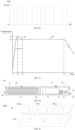
- FIG. 26 is a schematic diagram of an impulse voltage provided by the circuit board 140 to the first electrode 21 and the second electrode 22.
- the circuit board 140 shown in FIG. 25 includes the following circuits:
- An inverting boost circuit 1411 performs a first inverting boost on a direct-current voltage outputted by the cell 130.
- the voltage outputted by the cell 130 is 3.7-9.0 V; and the inverting boost circuit 1411 can process the voltage outputted by the cell 130 to form an alternating current with an amplitude tens of times greater.
- the inverting boost circuit 1411 may be a commonly used series or parallel LC oscillation circuit, or a purchased inverting boost IC, such as an inverting boost IC with a model of MAX774ESA+T from "Hengnuo core technology”, an inverting boost IC with a model of SN74HCT14N from “Ruixin Bochuang electronics”, or an inverting boost IC with a model of SN74LVC1G38DCKR from "Dejie Xincheng technology”, or another IC that can achieve the same inverting boost function.
- an inverting boost IC with a model of MAX774ESA+T from "Hengnuo core technology” an inverting boost IC with a model of SN74HCT14N from “Ruixin Bochuang electronics”
- an inverting boost IC with a model of SN74LVC1G38DCKR from "Dejie Xincheng technology”
- another IC that can achieve the same
- a Cockcroft-Walton boost circuit 1412 is configured to perform a further boost on an alternating voltage outputted by the inverting boost circuit 1411, with a boost factor adjustable in the range of tens to hundreds of times, so that the amplitude of the output voltage meets the requirement for the plasma generator 20 to generate an electric field that breaks air down.
- the electrical term "Cockcroft-Walton boost circuit” is a voltage doubling circuit commonly used in the electrical field, and can perform a doubling boost and AC/DC conversion.
- a filter circuit 1413 filters an output voltage with an amplitude on the order of kilovolts after boosting by the Cockcroft-Walton boost circuit 1412, to obtain the high-frequency and high-voltage impulse voltage that meets the foregoing requirement shown in FIG. 26 to be provided to the plasma generator 20.
- the filter circuit 1413 may include a high-order filter, or a similar filter circuit, or the like.
- the circuit board 140 controls the amplitude and frequency of the high-frequency and high-voltage impulse voltage provided to the plasma generator 20 to be variable.
- the circuit board 140 provides high-voltage pulses to the plasma generator 20, for the plasma generator 20 to pulsedly or intermittently generate a breakdown field, and to pulsedly or intermittently discharge to break a gas down, to generate plasma, so that the aerosol-generating product 1000 can be stably heated or cooled.
- FIG. 27 is a schematic diagram of a heating curve of the aerosol-generating product 1000 within predetermined time according to an embodiment.
- the circuit board 140 controls the impulse voltage provided to the plasma generator 20 based on a required target temperature.
- the heating curve is within predetermined time, and the predetermined time is set based on the amount of aerosols that can be generated by the aerosol-generating product 1000, and the smoking duration (for example, 4 min) acceptable to users.
- the heating curve in FIG. 27 includes the following heating process:
- First stage S1 quickly heating from room temperature to a first preset temperature T1 within time t1 for preheating.
- Second stage S2 cooling down from the first preset temperature T1 to a second preset temperature T2 within time t2.
- Third stage S3 maintaining the heating temperature substantially at the preset temperature T2 until time t3, for the aerosol-generating product 1000 to be stably heated at the second preset temperature T2 to generate an aerosol for inhalation; and stopping providing power to a heater 30 after inhalation to naturally cool down the heater 30.
- the circuit board 140 controls the amplitude of the impulse voltage provided to the plasma generator 20 to be greater in the first stage S1 than in the second stage S2 and/or the third stage S3.
- the circuit board 140 controls the amplitude of the impulse voltage provided to the plasma generator 20 to be substantially constant, while the frequency and/or impulse width are/is variable within predetermined time.
- the circuit board 140 controls the frequency and/or impulse width of the impulse voltage provided to the plasma generator 20 to be substantially constant, while the amplitude of the impulse voltage is variable, so that the heating temperature of the aerosol-generating product 1000 is maintained at the required target temperature.
- the aerosol generation device provides air stably to the inlet of the plasma generator 20 by using an air pump 180, to be used as a gas source for breakdown.
- the air pump 180 may be preferably located between the air inlet 121 of the housing 10 and the inlet of the plasma generator 20.
- the air pump 180 is controlled by the circuit board 140.
- the air pump 180 under the control of the circuit board 140, operates with the plasma generator 20 at the same time.
- the circuit board 140 controls the air pump 180 to start to provide air stably to the inlet of the plasma generator 20, and starts the plasma generator 20 at the same time to generate plasma to be provided to the aerosol-generating product 1000.
- the air pump 180 is prevented from starting, and the plasma generator 20 is prevented from generating plasma.
- the circuit board 140 determines a smoking action of the user by using a sensing device such as an airflow sensor, to control the air pump 180 and the plasma generator 20 to start based on the sensed smoking action.
- a sensing device such as an airflow sensor
- the circuit board 140 determines a smoking action of the user by using a sensing device such as an airflow sensor, to control the air pump 180 and the plasma generator 20 to start based on the sensed smoking action.
- a sensing device such as an airflow sensor
- the circuit board 140 controls the air pump 180 to start or stop, to adjust the heating temperature of the aerosol-generating product 1000. For example, when a user is smoking, the circuit board 140 controls the air pump 180 to start or to increase the amount of air pumped; while when the user is not smoking, the circuit board 140 controls the air pump 180 to stop or to reduce the amount of air pumped by the air pump 180. Alternatively, in some other implementations, based on the heating process of the aerosol-generating product 1000 in FIG.
- the circuit board 140 controls the air pump 180 to operate at a smaller amount of air pumped than that when smoking, for air at a low flow rate or reduced air to pass through in the constant-temperature stage, which facilitates maintaining the heating temperature of the aerosol-generating product 1000 constant.
- FIG. 28 is a schematic diagram of an electronic atomization device according to an embodiment.
- the electronic atomization device is configured to atomize a liquid substrate to generate an aerosol for inhalation.
- the electronic atomization device 100 in this disclosure may also be represented as an aerosol generation system or a drug delivery product. Therefore, this device 100 or system may be adapted to provide one or more substances (such as flavor agents and/or active pharmaceutical ingredients) in an inhalable form or state.
- the inhalable substance may be substantially in an aerosol form (that is, fine solid particles or suspension droplets in a gas).
- FIG. 28 is a schematic diagram of a structure of the electronic atomization device 100 according to an embodiment.
- the device usually includes several components disposed in an external body or outer shell (which may be referred to as a housing).
- the overall design of the external body or outer shell may vary, and the type or configuration of the external body that may limit the overall size and shape of the electronic atomization device 100 may vary.
- an elongated body similar to the shape of a cigarette or cigar may be formed from a single integrated housing, or an elongated housing may be formed from two or more separable bodies.
- the electronic atomization device 100 may have a control body at one end, where the control body has a housing including one or more reusable components (for example, batteries such as rechargeable batteries and/or rechargeable supercapacitors, and various electronic devices for controlling operations of the product); and at the other end, may have an external body or outer shell that can be removably coupled and includes disposable parts (for example, a disposable flavor-containing cartridge).
- reusable components for example, batteries such as rechargeable batteries and/or rechargeable supercapacitors, and various electronic devices for controlling operations of the product
- disposable parts for example, a disposable flavor-containing cartridge
- the electronic atomization device 100 includes an atomizer 10 that stores a liquid substrate and atomizes the liquid substrate to generate an aerosol, and a power supply mechanism 20 that supplies power to the atomizer 10.
- the power supply mechanism 20 and the atomizer 10 are detachably aligned based on a functional relationship.
- the atomizer 10 may be connected to the power supply mechanism 20 by using various structures, to generate a threaded connection, a press-fit connection, an interference fit, a magnetic connection, and the like.
- the electronic atomization device 100 when the atomizer 10 and the power supply mechanism 20 are in an assembled configuration, the electronic atomization device 100 may be substantially in a rod shape, a flat-cylinder shape, a bar shape, a column shape, or the like.
- the power supply mechanism 20 and the atomizer 10 may include separate housings or external bodies that may be made of any of different materials.
- the housing may be made of any suitable and structurally intact material.
- the housing may be made of a metal or an alloy such as stainless steel or aluminum.
- Other suitable materials include various plastics (for example, polycarbonate), metal-plating over plastics, ceramics, and the like.
- the electronic atomization device 100 has a proximal end 110 and a distal end 120 opposite to each other in a length direction.
- the proximal end 110 is usually used as the end for a user to smoke
- the distal end 120 is the end away from the user.
- the atomizer 10 is arranged at the proximal end
- the power supply mechanism 20 is arranged at the distal end 120.
- the power supply mechanism 20 includes:
- the atomizer 10 includes:
- the capillary element 12 is, for example, a porous body made of cellucotton, porous ceramic, porous glass, or foam metal, or a capillary tube.
- the liquid transfer element 13 may be a micro-pump to pump a predetermined amount of liquid substrate from the liquid storage cavity 11 to the capillary element 12; and a suitable micro-pump is, for example, a micro-pump based on the micro electro mechanical system (MEMS) technology.
- MEMS micro electro mechanical system
- Examples of the suitable micro-pump include a micro-pump with the model MDP2205 from thinXXS Microtechnology AG, micro-pumps with the models mp5 and mp6 from Bartels Mikrotechnik GmbH, a piezoelectric micro-pump from Takasago Fluidic Systems, and other micro-pumps.
- the circuit board 22 includes several electronic components, and in some examples, may be formed on a printed circuit board (PCB) that supports and electrically connects the electronic components.
- the electronic components may include a microprocessor or processor core, and a memory.
- a control component may include a microcontroller having an integrated processor core and memory, and may further include one or more integrated input/output peripherals.
- the circuit board 22 is configured to provide required high-voltage pulses to the plasma generator 30, for the plasma generator to break air down through discharge to generate plasma.
- the plasma generator 30 is constructed as described in the foregoing embodiment.
Landscapes
- Physics & Mathematics (AREA)
- Engineering & Computer Science (AREA)
- Plasma & Fusion (AREA)
- Spectroscopy & Molecular Physics (AREA)
- Plasma Technology (AREA)
Abstract
Description
- This application claims priority to
Chinese Patent Application No. 202210287746.X, filed with the China National Intellectual Property Administration on March 22, 2022 - Embodiments of this application relate to the field of aerosol generation technologies through heating but not burning, and in particular, to an aerosol generation device.
- Tobacco products (such as cigarettes and cigars) are used by burning tobacco to produce tobacco smoke. Attempts are made to replace these tobacco-burning products by manufacturing products that release compounds without burning.
- An example of this type of products is a heating device that releases compounds by heating rather than burning materials. For example, the materials may be an aerosol-generating product including tobacco or other non-tobacco products, where these non-tobacco products may or may not include nicotine. To heat the aerosol-generating product to a temperature at which volatile components that can form aerosols can be released, an existing heating device usually heats the aerosol-generating product by using a resistance heating element or an electromagnetic induction heating element.
- An embodiment of this application provides an aerosol generation device, configured to heat an aerosol-generating product to generate an aerosol, including:
- a plasma generator, configured to generate plasma to heat the aerosol-generating product through the plasma.
- In a more preferred implementation, the plasma is constructed to be generated by applying a breakdown voltage to a gas to break the gas down.
- In a more preferred implementation, the gas includes at least one of air, helium, and neon.
- In a more preferred implementation, an electron number density of the plasma generated by the plasma generator is 1010/cm3-1013/cm3.
- In a more preferred implementation, the plasma generated by the plasma generator further includes two or more of oxygen atoms, excited-state nitrogen molecules, ozone molecules, hydroxyl groups, oxygen ions, nitrogen ions, and nitrogen oxide molecules.
- In a more preferred implementation, the plasma generator is based on atmospheric-pressure glow discharge.
- In a more preferred implementation, the plasma generated by the plasma generator is non-equilibrium plasma.
- In a more preferred implementation, the plasma generator is provided based on dielectric barrier discharge.
- In a more preferred implementation, the plasma generator is provided based on micro hollow cathode discharge.
- In a more preferred implementation, the plasma generator is configured with:
- an inlet, for the gas to enter; and
- an outlet, for outputting the plasma.
- In a more preferred implementation, the inlet and the outlet are aligned in an axial direction of the plasma generator.
- In a more preferred implementation, the inlet and the outlet are staggered relative to each other in an axial direction of the plasma generator.
- In a more preferred implementation, no obstacle that blocks the plasma exists between the outlet and the aerosol-generating product.
- In a more preferred implementation, the plasma generator includes a first electrode and a second electrode that are spaced apart, to form a breakdown field between the first electrode and the second electrode to break the gas down to generate the plasma.
- In a more preferred implementation, the breakdown field is 10-50 kV/cm.
- In a more preferred implementation, the first electrode and the second electrode are arranged substantially in parallel.
- In a more preferred implementation, a spacing distance between the first electrode and the second electrode is 10-2000 µm. In a more preferred implementation, a spacing distance between the first electrode and the second electrode cannot be less than 5 µm.
- In a more preferred implementation, the first electrode and/or the second electrode are/is in a shape of a sheet or plate or ring or tube.
- In a more preferred implementation, the first electrode and/or the second electrode are/is rigid.
- In a more preferred implementation, the first electrode and/or the second electrode are/is thin.
- In a more preferred implementation, the first electrode and/or the second electrode have/has a length, a width, and a thickness; and the thickness of the first electrode and/or the second electrode is less than the length and the width.
- In a more preferred implementation, the first electrode and/or the second electrode have/has a thickness of 0.05-0.5 mm.
- In a more preferred implementation, the first electrode and/or the second electrode have/has the same shape or size.
- In a more preferred implementation, the first electrode and/or the second electrode have/has resistivity of about 1×10⁻⁵-1×10⁻⁹ Ωm.
- In a more preferred implementation, the first electrode and/or the second electrode include/includes copper, gold, silver, platinum, or an alloy thereof.
- In a more preferred implementation, the breakdown field is intermittent or pulsed.
- In a more preferred implementation, the plasma generator further includes:
a dielectric, at least partially located between the first electrode and the second electrode, for inhibiting discharge-to-arc transition between the first electrode and the second electrode. - In a more preferred implementation, the dielectric is arranged to be a coating or film layer formed on a surface of the first electrode and/or the second electrode.
- In a more preferred implementation, a dielectric constant of the dielectric is greater than 5.
- In a more preferred implementation, the dielectric includes at least one of aluminum oxide, zirconium oxide, ceramic, glass, quartz, and an organic polymer.
- In a more preferred implementation, the plasma generator has a fluid channel running through the plasma generator; and
the fluid channel at least partially extends in the dielectric; or the fluid channel is at least partially formed between the dielectric and the first electrode; or the fluid channel is at least partially formed between the dielectric and the second electrode. - In a more preferred implementation, one of the first electrode and the second electrode is located inside the dielectric, and the other is located outside the dielectric.
- In a more preferred implementation, the aerosol generation device further includes:
a substrate, arranged to emit heat by receiving at least partial plasma from the plasma generator, to heat the aerosol-generating product. - In a more preferred implementation, the substrate at least partially defines a cavity for receiving the aerosol-generating product.
- In a more preferred implementation, the substrate includes a metal or an alloy.
- In a more preferred implementation, thermal conductivity of the substrate is greater than 40 W/mK.
- In a more preferred implementation, the substrate is arranged to be not in contact with the plasma generator; and/or
the substrate is arranged to be in contact with the aerosol-generating product. - In a more preferred implementation, the plasma generator is arranged to at least partially surround the substrate.
- In a more preferred implementation, the substrate is provided with a hole, and at least partial plasma from the plasma generator is outputted to the aerosol-generating product through the hole.
- In a more preferred implementation, the plasma generator is provided with a high-voltage pulse power supply.
- In a more preferred implementation, the aerosol generation device further includes:
- a cell; and
- a circuit board, located between the cell and the plasma generator, and configured to guide and provide an impulse voltage to the plasma generator for the plasma generator to generate the plasma.
- In some other varying implementations, a direct-current voltage, an alternating-current voltage, a radio-frequency voltage, or the like is provided to the plasma generator, and then an electric field is generated through the excitation by the direct-current voltage, the alternating-current voltage, the radio-frequency voltage, or the like, to break a gas down to generate plasma. Alternatively, the plasma generator is excited by a direct-current voltage, an alternating-current voltage, or a radio-frequency voltage to generate an electric field to break a gas down to generate plasma.
- In a more preferred implementation, frequency of the impulse voltage is 1-100 kHz.
- In a more preferred implementation, a voltage amplitude of the impulse voltage is 1-9 kV.
- In a more preferred implementation, an impulse width of the impulse voltage is 10-600 ns.
- In a more preferred implementation, the impulse voltage is obtained by boosting an output voltage of the cell at least twice.
- In a more preferred implementation, the circuit board includes:
- an inverting boost circuit, configured to perform a first boost on a direct-current voltage outputted by the cell;
- a Cockcroft-Walton boost circuit, for performing a second boost on an output voltage of the inverting boost circuit; and
- a filter circuit, for filtering an output voltage of the Cockcroft-Walton boost circuit to form the impulse voltage.
- In a more preferred implementation, the plasma generator is constructed to extend substantially in a longitudinal direction of the aerosol generation device.
- In a more preferred implementation, the plasma generator is constructed to be substantially perpendicular to a longitudinal direction of the aerosol generation device.
- In a more preferred implementation, the aerosol generation device further includes:
- a cavity, configured to receive the aerosol-generating product, where
- the plasma generator and the cavity are substantially arranged coaxially.
- In a more preferred implementation, the aerosol generation device further includes:
- a cavity, configured to receive the aerosol-generating product, where
- the plasma generator and the cavity are spaced apart in a longitudinal direction of the aerosol generation device.
- In a more preferred implementation, the aerosol generation device further includes:
- a cavity, configured to receive the aerosol-generating product, where
- the plasma generator is arranged to at least partially surround the cavity.
- In a more preferred implementation, the plasma generator has a fluid channel running through the plasma generator.
- In a more preferred implementation, the fluid channel substantially extends straight.
- In a more preferred implementation, the fluid channel is constructed to run through the plasma generator in an axial direction.
- In a more preferred implementation, the fluid channel has an inner diameter of 0.1-0.9 mm.
- In a more preferred implementation, the plasma generator further includes: a first conducting element and a second conducting element for supplying power to the plasma generator, where
- the first conducting element is electrically conductive with the first electrode; and
- the second conducting element is electrically conductive with the second electrode.
- In a more preferred implementation, the first conducting element is further arranged to at least partially provide support to the first electrode; and/or
the second conducting element is further arranged to at least partially provide support to the second electrode. - In a more preferred implementation, the first conducting element and/or the second conducting element are/is constructed to be in a shape of a ring or tube.
- In a more preferred implementation, the first conducting element and the second conducting element are arranged coaxially.
- In a more preferred implementation, the first electrode and/or the first conducting element are/is located in the second conducting element.
- In a more preferred implementation, the plasma generator further includes:
- a dielectric, including an end part arranged perpendicular to a longitudinal direction of the conductive medium and a peripheral part extending from the end part, where
- the end part is arranged to be at least partially located between the first electrode and the second electrode, for inhibiting discharge-to-arc transition between the first electrode and the second electrode; and
- the peripheral part is arranged to be at least partially located between the first conducting element and the second conducting element, to provide insulation between the first conducting element and the second conducting element.
- In a more preferred implementation, the plasma generator further includes:
an outer cover, at least partially defining an outer surface of the plasma generator, and making the surface of the plasma generator electrically insulated. - In a more preferred implementation, the outer cover is further arranged to accommodate and hold the first electrode and the second electrode.
- In a more preferred implementation, the plasma generator further includes:
- a first conducting lead and a second conducting lead for supplying power to the plasma generator, where
- the first conducting lead at least partially extends from an outside of the outer cover to an inside of the outer cover, to be electrically connected to the first electrode; and/or the second conducting lead at least partially extends from an outside of the outer cover to an inside of the outer cover, to be electrically connected to the second electrode.
- In a more preferred implementation, the plasma generator is constructed to output the plasma in a longitudinal direction of the plasma generator.
- In a more preferred implementation, the aerosol generation device further includes:
- a resistance heating element, to heat the aerosol-generating product through Joule heating; and/or
- an induction heating element, to heat the aerosol-generating product by being penetrated by a varying magnetic field to emit heat; and/or
- an infrared heating element, to heat the aerosol-generating product by radiating an infrared ray to the aerosol-generating product.
- In a more preferred implementation, the plasma generator includes at least:
a first plasma generator and a second plasma generator, configured to independently output the plasma to different parts of the aerosol-generating product, to independently heat the different parts of the aerosol-generating product. - In a more preferred implementation, the first plasma generator and the second plasma generator are configured to heat the different parts of the aerosol-generating product one after the other.
- In a more preferred implementation, the plasma generator includes at least:
a first plasma generator and a second plasma generator, configured to heat different parts of the aerosol-generating product according to different preset temperatures, to heat the different parts of the aerosol-generating product to the different temperatures. - In a more preferred implementation, the plasma generator includes at least:
- a first plasma generator and a second plasma generator that are arranged adjacent to each other in a longitudinal direction; and
- a mechanical isolator, disposed between the first plasma generator and the second plasma generator, and constructed and provided to keep a distance between the adjacent first plasma generator and second plasma generator.
- In a more preferred implementation, the mechanical isolator is insulated and is configured to provide insulation between the adjacent first plasma generator and second plasma generator.
- In a more preferred implementation, the mechanical isolator is in a shape of a ring or tube.
- In a more preferred implementation, the aerosol generation device further includes:
- an air inlet, for outside air to enter; and
- a support element or support wall, located between the air inlet and the plasma generator, and at least partially providing support to the plasma generator, where
- the support element or support wall further defines an air channel connecting the air inlet and the plasma generator.
- Another embodiment of this application further provides an aerosol generation device, configured to heat an aerosol-generating product to generate an aerosol, including:
- a plasma generator, configured to generate plasma; and
- a substrate, arranged to emit heat by receiving the plasma from the plasma generator, to heat the aerosol-generating product.
- In a more preferred implementation, the substrate at least partially defines a cavity for receiving the aerosol-generating product.
- Another embodiment of this application further provides an aerosol generation device, configured to heat an aerosol-generating product to generate an aerosol, including:
a first plasma generator and a second plasma generator that are spaced apart in a longitudinal direction, configured to output plasma to different parts of the aerosol-generating product one after the other, to sequentially heat the different parts of the aerosol-generating product. - Another embodiment of this application further provides an aerosol generation device, configured to heat an aerosol-generating product to generate an aerosol, including:
- a plasma generator, configured to provide plasma to heat the aerosol-generating product; and
- a circuit board, configured to guide and provide an impulse voltage to the plasma generator for the plasma generator to stably provide the plasma to the aerosol-generating product, to stably heat or cool the aerosol-generating product.
- In the foregoing aerosol generation devices, the plasma generator provides the plasma to the aerosol-generating product to heat the aerosol-generating product.
- Another embodiment of this application further provides an electronic atomization device, configured to atomize a liquid substrate to generate an aerosol, including:
- a liquid storage cavity, configured to store the liquid substrate;
- a capillary element, configured to receive and hold the liquid substrate from the liquid storage cavity; and
- a plasma generator, configured to provide plasma to the capillary element to at least partially heat and atomize the liquid substrate in the capillary element through plasma heating to generate the aerosol.
- In a more preferred implementation, the capillary element includes a porous body, a porous fiber, a capillary tube, and the like.
- In a more preferred implementation, the electronic atomization device further includes:
a liquid transfer element, configured to provide the liquid substrate from the liquid storage cavity to the capillary element. The liquid transfer element includes a liquid pump. - Another embodiment of this application further provides an aerosol generation device, configured to heat an aerosol-generating product to generate an aerosol, including an outer shell, where the outer shell is configured with:
- a cavity, for at least partially receiving the aerosol-generating product;
- a power supply component, configured to supply power; and
- a plasma generator, configured to output plasma to the aerosol-generating product received in the cavity, where the plasma generator includes:
- a first electrode and a second electrode that are spaced apart, configured to form a breakdown field when powered by the power supply component, to break a gas down to generate the plasma;
- a dielectric, at least partially located between the first electrode and the second electrode, for inhibiting discharge-to-arc transition between the first electrode and the second electrode;
- an inlet, for the gas to enter; and
- an outlet, for outputting the plasma.
- In a more preferred implementation, the plasma generator is spaced apart from the cavity in a longitudinal direction of the outer shell, and is constructed to output the plasma in the longitudinal direction of the outer shell to the aerosol-generating product received in the cavity.
- In a more preferred implementation, the aerosol generation device further includes:
an air channel, located in the longitudinal direction of the outer shell between the outlet of the plasma generator and the cavity, for providing a path for the plasma to be outputted from the plasma generator to the aerosol-generating product. - In a more preferred implementation, the air channel extends straight.
- In a more preferred implementation, the air channel has an extended length of 10-30 mm; or
a distance between the plasma generator and the cavity is 10-30 mm. - In a more preferred implementation, a spacing distance between the first electrode and the second electrode is 10-2000 µm.
- In a more preferred implementation, the first electrode and the second electrode are substantially planar and are arranged perpendicular to the longitudinal direction of the outer shell.
- In a more preferred implementation, the first electrode and/or the second electrode have/has a thickness of 0.05-0.5 mm.
- In a more preferred implementation, a dielectric constant of the dielectric is greater than 5.
- In a more preferred implementation, one of the first electrode and the second electrode is located inside the dielectric, and the other is located outside the dielectric.
- In a more preferred implementation, the plasma generator further includes: a first conducting element and a second conducting element, located between the power supply component and the plasma generator, for forming an electrical connection between the power supply component and the plasma generator, where
- the first conducting element is electrically conductive with the first electrode; and
- the second conducting element is electrically conductive with the second electrode.
- In a more preferred implementation, the first conducting element is further arranged to at least partially provide support to the first electrode; and/or
the second conducting element is further arranged to at least partially provide support to the second electrode. - In a more preferred implementation, the first conducting element and/or the second conducting element are/is constructed to be in a shape of a ring or tube.
- In a more preferred implementation, the first conducting element and the second conducting element are arranged coaxially.
- In a more preferred implementation, the first electrode and/or the first conducting element are/is located in the second conducting element.
- In a more preferred implementation, the plasma generator further includes:
- a dielectric, including an end part arranged perpendicular to a longitudinal direction of the conductive medium and a peripheral part extending from the end part, where
- the end part is arranged to be at least partially located between the first electrode and the second electrode; and
- the peripheral part is arranged to be at least partially located between the first conducting element and the second conducting element, to provide electrical insulation between the first conducting element and the second conducting element.
- In a more preferred implementation, the outlet and the inlet of the plasma generator are provided opposite to each other in the longitudinal direction.
- In a more preferred implementation, the plasma generator further includes a fluid channel extending between the inlet and the outlet; and
the fluid channel is at least partially located between the first electrode and the second electrode. - In a more preferred implementation, the plasma generator further includes:
an outer cover, at least partially defining an outer surface of the plasma generator, and making the surface of the plasma generator electrically insulated. - In a more preferred implementation, the outer cover is further arranged to accommodate and hold the first electrode and the second electrode.
- In a more preferred implementation, the plasma generator further includes:
- a first conducting lead and a second conducting lead for supplying power to the plasma generator, where
- the first conducting lead at least partially extends from an outside of the outer cover to an inside of the outer cover, to be electrically connected to the first electrode; and/or the second conducting lead at least partially extends from an outside of the outer cover to an inside of the outer cover, to be electrically connected to the second electrode.
- In a more preferred implementation, the aerosol generation device further includes:
- an air inlet, for outside air to enter; and
- a support element or support wall, located between the air inlet and the plasma generator, and at least partially providing support to the plasma generator, where
- the support element or support wall further defines an air channel connecting the air inlet and the plasma generator.
- In a more preferred implementation, the inlet includes one or more holes formed on one of the first electrode and the second electrode; and/or
the outlet includes one or more holes formed on the other of the first electrode and the second electrode. - In a more preferred implementation, the power supply component is configured to provide an impulse voltage; and
the first electrode and the second electrode are configured to form a breakdown field when excited by the impulse voltage, to break a gas down to generate the plasma. - In some other varying implementations, the plasma generator may be further excited by a direct-current voltage, an alternating-current voltage, a radio-frequency voltage, or the like to generate an electric field to break a gas down to generate plasma.
- In a more preferred implementation, the power supply component includes:
- a cell, configured to provide a direct-current voltage; and
- a circuit board, configured to convert the direct-current voltage provided by the cell into an impulse voltage for outputting.
- Another embodiment of this application further provides a plasma generator for an aerosol generation device, including:
- a first electrode and a second electrode that are spaced apart, configured to form a breakdown field when excited by the impulse voltage, to break a gas down to generate the plasma, where the first electrode and the second electrode are substantially planar and are arranged perpendicular to a longitudinal direction of the plasma generator;
- a dielectric, at least partially located between the first electrode and the second electrode, for inhibiting discharge-to-arc transition between the first electrode and the second electrode;
- an inlet, for the gas to enter; and
- an outlet, for outputting the plasma.
- Another embodiment of this application further provides an aerosol generation device, configured to heat an aerosol-generating product to generate an aerosol, including:
- a substrate, for at least partially receiving the aerosol-generating product;
- a power supply component, configured to supply power; and
- a plasma generator, at least partially surrounding the substrate, and configured to output plasma to the substrate for the substrate to emit heat to heat the aerosol-generating product, where the plasma generator includes:
- a first electrode and a second electrode that are spaced apart, configured to form a breakdown field when excited by the impulse voltage, to break a gas down to generate the plasma;
- a dielectric, at least partially located between the first electrode and the second electrode, for inhibiting discharge-to-arc transition between the first electrode and the second electrode;
- an inlet, for the gas to enter; and
- an outlet, for outputting the plasma to the substrate.
- One or more embodiments are exemplarily described with reference to the corresponding figures in the accompanying drawings, and these exemplary descriptions are not to be construed as limiting the embodiments. Elements that have same reference numerals in the accompanying drawings indicate similar elements. Unless otherwise particularly stated, the figures in the accompanying drawings are not drawn to scale.
-
FIG. 1 is a schematic diagram of an aerosol generation device according to an embodiment; -
FIG. 2 is a schematic diagram of a plasma generator inFIG. 1 according to an embodiment; -
FIG. 3 is a schematic diagram of a plasma generator inFIG. 1 according to another embodiment; -
FIG. 4 is a schematic diagram of a plasma generator inFIG. 1 according to another embodiment; -
FIG. 5 is a schematic diagram of a plasma generator inFIG. 1 according to another embodiment; -
FIG. 6 is a schematic diagram of a plasma generator inFIG. 1 according to another embodiment; -
FIG. 7 is a schematic diagram of a plasma generator inFIG. 1 according to another embodiment; -
FIG. 8 is a schematic diagram of a plasma generator inFIG. 1 according to another embodiment; -
FIG. 9 is a schematic diagram of an aerosol generation device according to another embodiment; -
FIG. 10 is a schematic diagram of a plasma generator inFIG. 9 from a view angle; -
FIG. 11 is a schematic diagram of a plasma generator inFIG. 9 from another view angle; -
FIG. 12 is a schematic exploded diagram of all parts of a plasma generator inFIG. 9 from a view angle; -
FIG. 13 is a schematic exploded diagram of all parts of a plasma generator inFIG. 9 from another view angle; -
FIG. 14 is a schematic cross-sectional view of a plasma generator inFIG. 9 from a view angle; -
FIG. 15 is a schematic exploded diagram of a first electrode and a second electrode before assembly according to another embodiment; -
FIG. 16 is a schematic exploded diagram of a first electrode and a second electrode before assembly according to another embodiment; -
FIG. 17 is a schematic diagram of an aerosol generation device according to another embodiment; -
FIG. 18 is a schematic cross-sectional view of a plasma generation mechanism inFIG. 17 from a view angle; -
FIG. 19 is a schematic exploded diagram of a plasma generation mechanism inFIG. 18 from a view angle; -
FIG. 20 is a schematic planar diagram of a first plasma generator inFIG. 19 from a view angle; -
FIG. 21 is a schematic exploded diagram of a first plasma generator inFIG. 20 ; -
FIG. 22 is an enlarged view of B inFIG. 18 ; -
FIG. 23 is a schematic diagram of an aerosol generation device according to another embodiment; -
FIG. 24 is a schematic diagram of an aerosol generation device according to another embodiment; -
FIG. 25 is a block diagram of some circuits of a circuit board according to an embodiment; -
FIG. 26 is a schematic diagram of an impulse voltage provided by a circuit board to a plasma generator according to an embodiment; -
FIG. 27 is a schematic diagram of a heating curve of an aerosol-generating product according to an embodiment; -
FIG. 28 is a schematic diagram of an electronic atomization device according to another embodiment; -
FIG. 29 is a schematic diagram of a plasma generator according to another embodiment; and -
FIG. 30 is a schematic diagram of a plasma generator according to another embodiment. - For ease of understanding of this application, this application is described below in more detail with reference to the accompanying drawings and specific implementations.
- An embodiment of the present invention provides an aerosol generation device that heats but not burns an aerosol-generating
product 1000, for example, a cigarette, to volatilize or release at least one of components of the aerosol-generatingproduct 1000 to form an aerosol for inhalation. - Further, in an optional implementation, the aerosol-generating
product 1000 is preferably made of a tobacco-containing material that releases a volatile compound from a substrate when being heated, or may be made of a non-tobacco material suitable for releasing smoke through electrical heating after being heated. The aerosol-generatingproduct 1000 preferably uses a solid substrate, which may include one or more of powders, particles, fragmented strips, strips, or flakes of one or more of vanilla leaves, tobacco leaves, homogeneous tobacco, and expanded tobacco. Alternatively, the solid substrate may include additional tobacco or non-tobacco volatile aroma compounds to be released when the substrate is heated. - According to an embodiment of the present invention, an aerosol generation device generates plasma and heats the aerosol-generating
product 1000 using the plasma. - A configuration of an aerosol generation device according to an embodiment of the present invention may be shown in
FIG. 1 andFIG. 2 . The overall shape of the device is roughly configured into a flat cylinder shape, and an external member of theaerosol generation device 100 includes:
ahousing 10, having a hollow structure inside, to form an assembly space for a component with a necessary function, for example, plasma generation, where thehousing 10 has aproximal end 110 and adistal end 120 opposite to each other in a length direction. - The
proximal end 110 is provided with anopening 111, and the aerosol-generatingproduct 1000 may be received in thehousing 10 through theopening 111 to be heated or removed from thehousing 10. - The
distal end 120 is provided with anair inlet 121, where theair inlet 121 is provided to supply outside air into thehousing 10 during inhalation; and a charging interface 122, such as a USB type-C interface or a pin interface, for charging the aerosol generation device after being connected to an external power supply or an adapter. - Further, as shown in
FIG. 1 , theaerosol generation device 100 further includes: - a
cavity 170, configured to accommodate or receive the aerosol-generatingproduct 1000, where the aerosol-generatingproduct 1000 may be removably received in thecavity 170 through theopening 111 during use; - a
cell 130, configured to supply power, where thecell 130 is preferably a chargeable direct-current cell 130 and can be connected to an external power supply through the charging interface 122 for charging; and - a
circuit board 140. - Further, as shown in
FIG. 1 , theaerosol generation device 100 further includes:
aplasma generator 20, configured to generate plasma and heat, using the plasma, the aerosol-generatingproduct 1000 received in thecavity 170. - In the foregoing implementations, the physical term "plasma" is a mixture of electrons, ions, atoms, and atomic groups generated through the ionization of gas molecules when an applied voltage reaches a breakdown voltage.
- In a preferred implementation, the
plasma generator 20 is a generator that generates plasma by applying a breakdown voltage on a gas to discharge to break the gas down. The physical term "breakdown" indicates that a dielectric loses its dielectric property and becomes a conductor under the action of a sufficiently strong electric field; and a voltage that "breaks down" the dielectric is the "breakdown voltage". - In physics, the "plasma" may be divided based on particle temperatures into equilibrium plasma (where an electron temperature is essentially equal to an ion temperature) and non-equilibrium plasma (where an electron temperature is much higher than an ion temperature). In a more preferred implementation, the plasma generated by the
plasma generator 20 is non-equilibrium plasma. The physical term "non-equilibrium plasma" is low-temperature plasma with a low degree of ionization, where the electron temperature is much higher than the ion temperature. The non-equilibrium plasma is in a partially ionized state, where the electron temperature is usually of a few electron volts (1 eV = 11600 K of corresponding energy), and a gas temperature (close to the ion temperature) is of a few hundred degrees Celsius. - In some preferred implementations, the
plasma generator 20 is based on atmospheric-pressure glow discharge (APGD). Theplasma generator 20 based on atmospheric-pressure glow discharge operates in an open environment with an operating gas of air at atmospheric pressure. - Further, as shown in
FIG. 1 , theplasma generator 20 is a generator that generates plasma by discharging to break air down. InFIG. 1 , theplasma generator 20 includes: - an
inlet 210, for air to enter theplasma generator 20, where theairflow inlet 210 is connected to theair inlet 121 through anair channel 150, and the air can enter theplasma generator 20 through theair inlet 121 along an arrow R11 in the figure; and - an
outlet 220, connected to thecavity 170 through achannel 160, for emitting or outputting the plasma along an arrow R2 in the figure during use to the aerosol-generatingproduct 1000 in thecavity 170 through thechannel 160, to heat the aerosol-generatingproduct 1000. - In some implementations, there is no obstacle or barrier between the
outlet 220 and the aerosol-generatingproduct 1000, so that the plasma can be directly emitted or outputted or applied to the aerosol-generatingproduct 1000. In this case, one part of the plasma can directly transfer thermal energy from the plasma gas to the aerosol-generatingproduct 1000 for heating; and the other part of the plasma enables active particles (electrons, ions, free radicals, and the like) to undergo a series of physicochemical reactions with the aerosol-generatingproduct 1000 to heat the aerosol-generatingproduct 1000. - In an implementation, airflow channels are formed in the
aerosol generation device 100 between theair inlet 121 and theopening 111, to jointly define an airflow path from theair inlet 121 to theopening 111 or thecavity 170 through theplasma generator 20. In addition, at least some of the airflow channels run through theplasma generator 20. Alternatively, at least some of the airflow channels are located in theplasma generator 20. Alternatively, theplasma generator 20 is at least partially exposed to the airflow channels. - Alternatively, as shown in
FIG. 1 , in another varying implementation, theaerosol generation device 100 further includes:
agas source 30, configured to provide theplasma generator 20 with a gas that can generate plasma by discharge breakdown. In this varying embodiment, the gas stored in thegas source 30 and provided to theplasma generator 20 is helium, neon, or the like that is more stable than plasma generated by air breakdown. In use, thegas source 30 provides the gas to theplasma generator 20 through theair channel 150 along an arrow R12. -
FIG. 2 is a schematic diagram of theplasma generator 20 according to an embodiment. In this embodiment, theplasma generator 20 includes:
afirst electrode 21 and asecond electrode 22 that are spaced apart, to form an electric field therebetween for discharging to break down air or the gas from thegas source 30. - In some implementations, a breakdown field formed between the
first electrode 21 and thesecond electrode 22 is about 10-50 kV/cm; more preferably, the breakdown field formed between thefirst electrode 21 and thesecond electrode 22 is about 20-40 kV/cm; and more preferably, the breakdown field formed between thefirst electrode 21 and thesecond electrode 22 is 28-32 kV/cm. - In addition, in a more preferred implementation, the
plasma generator 20 is based on micro hollow cathode discharge (MHCD) excited by high-voltage pulses; and in use, the high-voltage pulses are provided to theplasma generator 20, specifically to thefirst electrode 21 and thesecond electrode 22, for theplasma generator 20 to generate a pulsed electric field to generate plasma. - The
first electrode 21 and thesecond electrode 22 are arranged substantially in parallel; and a spacing distance between thefirst electrode 21 and thesecond electrode 22 is greater than 10 µm and less than 2000 µm. More preferably, the spacing distance between thefirst electrode 21 and thesecond electrode 22 is 500-1500 µm; and more preferably, the spacing distance between thefirst electrode 21 and thesecond electrode 22 is 800-1200. The spacing distance between thefirst electrode 21 and thesecond electrode 22 cannot be less than 5 µm. - In a preferred implementation shown in
FIG. 2 , thefirst electrode 21 and/or thesecond electrode 22 are/is a plate electrode, a coaxially arranged ring electrode, or the like. - Alternatively, the
first electrode 21 and/or thesecond electrode 22 are/is thin. Further, thefirst electrode 21 and/or thesecond electrode 22 are/is in a shape of a thin sheet or plate. Alternatively, thefirst electrode 21 and/or thesecond electrode 22 have/has a length, a width, and a thickness; and the thickness of thefirst electrode 21 and/or thesecond electrode 22 is less than the length and the width. - In some preferred implementations, the
first electrode 21 and/or thesecond electrode 22 have/has a thickness of about 0.05-0.5 mm; and more preferably, thefirst electrode 21 and/or thesecond electrode 22 have/has a thickness of about 0.1-0.3 mm. - In some preferred implementations, a distance between the
first electrode 21 and/or thesecond electrode 22 is 0.1-0.8 mm; more preferably, the distance between thefirst electrode 21 and/or thesecond electrode 22 is 0.2-0.6 mm; and more preferably, the distance between thefirst electrode 21 and/or thesecond electrode 22 is 0.4-0.5 mm. - Alternatively, the
first electrode 21 and/or thesecond electrode 22 are/is round or rectangular or curved or bowed or ring-shaped. - The
first electrode 21 and/or thesecond electrode 22 are/is rigid. The material term "rigidity" is opposed to "flexibility". Usually, the "rigidity" is the property of a material or object to be hard and not easily deformed, and is usually measured by using a physical parameter such as stiffness or modulus of elasticity. - The
first electrode 21 and/or thesecond electrode 22 are/is arranged in parallel. - The
first electrode 21 and/or thesecond electrode 22 may have the same shape or size. - Moreover, the
first electrode 21 and/or thesecond electrode 22 are/is usually made of a low-resistivity material such as copper, gold, silver, platinum, or an alloy thereof. - The
first electrode 21 and/or thesecond electrode 22 have/has resistivity of about 1×10⁻⁵-1×10⁻⁹ Ωm. - In some implementations, the
first electrode 21 and thesecond electrode 22 in theplasma generator 20 are respectively connected to thecircuit board 140 through wires. - In some more preferred embodiments, to inhibit the formation of discharge-to-arc transition between the
first electrode 21 and thesecond electrode 22, an electrically insulating dielectric is deposited, sprayed, or formed on a surface of thefirst electrode 21 facing thesecond electrode 22 and/or a surface of thesecond electrode 22 facing thefirst electrode 21. - Alternatively, in the embodiment shown in
FIG. 2 , theplasma generator 20 further includes:
at least one electrically insulatingdielectric 23, which facilitates inhibiting discharge-to-arc transition, and maintaining discharge stability and uniformity. - In some optional implementations, the dielectric is made of a material with a dielectric constant much greater than that of air. Usually, taking the dielectric constant of air as 1, the dielectric may be selected from at least one of aluminum oxide, zirconium oxide, ceramic, glass, quartz, and an organic polymer such as polytetrafluoroethylene (PTFE) with the dielectric constant greater than or even much greater than that of air. Preferably, a dielectric constant of the dielectric is greater than 5; and more preferably, the dielectric constant of the dielectric is greater than 10.
- Similarly, in some preferred implementations, the dielectric 23 is also in a shape of a thin sheet or plate. In some implementations, the dielectric 23 has a thickness of about 0.1-0.8 mm; more preferably, the dielectric 23 has a thickness of about 0.2-0.6 mm; and more preferably, the dielectric 23 has a thickness of about 0.4-0.5 mm.
- Further, as shown in
FIG. 2 , theplasma generator 20 in this embodiment includes:
afluid channel 24 extending between theinlet 210 and theoutlet 220, for air to enter and for outputting plasma. In the embodiment shown inFIG. 2 , thefluid channel 24 extends straight; and thefluid channel 24 is perpendicular to a thickness direction of theplasma generator 20. - The
inlet 210 is formed on thefirst electrode 21; and theoutlet 220 is formed on thesecond electrode 22. - In addition, in some preferred implementations, the
fluid channel 24 has an inner diameter of about 0.1-0.9 mm. Alternatively, in a more preferred implementation, thefluid channel 24 has an inner diameter of about 0.2-0.8 mm. In a more preferred implementation, thefluid channel 24 has an inner diameter of about 0.4-0.6 mm. - Further,
FIG. 3 is a schematic diagram of theplasma generator 20 according to another embodiment. In this embodiment, theplasma generator 20 includes: - a
first electrode 21a and asecond electrode 22a that are spaced apart; - at least one dielectric 23a or coating, located between the
first electrode 21a and thesecond electrode 22a; and - a
fluid channel 24a that curves and extends between aninlet 210a and anoutlet 220a. - The
fluid channel 24a at least partially extends parallel to thefirst electrode 21a and/or thesecond electrode 22a. In addition, thefluid channel 24a at least partially extends in the dielectric 23a. - Further,
FIG. 4 is a schematic diagram of theplasma generator 20 according to another embodiment. In this embodiment, theplasma generator 20 includes: - a
first electrode 21b and asecond electrode 22b that are spaced apart; and - at least one dielectric or coating, located between the
first electrode 21b and thesecond electrode 22b. Specifically, provided between thefirst electrode 21b and thesecond electrode 22b are: - a first dielectric or
coating 231b, located between thefirst electrode 21b and thesecond electrode 22b, and substantially close to or bonded to a surface of thefirst electrode 21b facing thesecond electrode 22b; and - a second dielectric or
coating 232b, located between thefirst electrode 21b and thesecond electrode 22b, and substantially close to or bonded to a surface of thesecond electrode 22b facing thefirst electrode 21b. - A
distance space 25b is kept between the first dielectric orcoating 231b and the second dielectric orcoating 232b. Thedistance space 25b is sealed in a circumferential direction. - Further, according to
FIG. 4 , theplasma generator 20 further includes:
aninlet 210b provided on thefirst electrode 21b and anoutlet 220b provided on thesecond electrode 22b; and afluid channel 241b extending from theinlet 210b to thedistance space 25b and afluid channel 242b extending from thedistance space 25b to theoutlet 220b. - Alternatively, further,
FIG. 5 is a schematic diagram of theplasma generator 20 according to another varying embodiment. In this embodiment, theplasma generator 20 includes: - a
first electrode 21c and asecond electrode 22c that are spaced apart, where thefirst electrode 21c and thesecond electrode 22c are thin sheets or plates arranged in a longitudinal direction; - a dielectric 23c, located between the
first electrode 21c and thesecond electrode 22b, and parallel to thefirst electrode 21c and thesecond electrode 22c; and - a
fluid channel 24c running through the dielectric 23c in the longitudinal direction, and aninlet 210c and anoutlet 220c defined at both ends. - Alternatively, further,
FIG. 6 is a schematic diagram of theplasma generator 20 according to another varying embodiment. In this embodiment, theplasma generator 20 includes: - a
first electrode 21d and asecond electrode 22d that are arranged in a longitudinal direction, where thefirst electrode 21d and thesecond electrode 22d are spaced apart from each other in a thickness direction perpendicular to thefirst electrode 21d and thesecond electrode 22d; and - a dielectric 23d arranged in the longitudinal direction and located between the
first electrode 21d and thesecond electrode 22d. Afluid channel 241d extending in the longitudinal direction is defined and formed between the dielectric 23d and thefirst electrode 21d, and thefluid channel 241d has an inlet 211c and anoutlet 221d that are opposite to each other in the longitudinal direction; and/or afluid channel 242d extending in the longitudinal direction is defined and formed between the dielectric 23d and thesecond electrode 22d, and thefluid channel 242d has aninlet 212d and anoutlet 222d that are opposite to each other in the longitudinal direction. - Alternatively, further,
FIG. 7 is a schematic diagram of theplasma generator 20 according to another varying embodiment. In this embodiment, theplasma generator 20 includes:
afirst electrode 21e and asecond electrode 22e that extend in a longitudinal direction, where thefirst electrode 21e is in a shape of a tube surrounding thesecond electrode 22e; and thesecond electrode 22e is in a shape of a column extending in the longitudinal direction, or the like. - The
first electrode 21e and thesecond electrode 22e are spaced apart; and a ring-shapeddielectric 23e surrounding thesecond electrode 22e exists between thefirst electrode 21e and thesecond electrode 22e. - A
fluid channel 24e is defined and formed between the dielectric 23e and thefirst electrode 21e or between the dielectric 23e and thesecond electrode 22e; and thefluid channel 24e has aninlet 210e and anoutlet 220e that are opposite to each other in the longitudinal direction. - Alternatively, further,
FIG. 8 is a schematic diagram of theplasma generator 20 according to another varying embodiment. In this embodiment, theplasma generator 20 includes: - a tubular
first electrode 21f and a tubularsecond electrode 22f that are coaxially arranged; - a
tubular dielectric 23f located between thefirst electrode 21f and thesecond electrode 22f; and - a
fluid channel 24f, formed between the dielectric 23f and thefirst electrode 21f and/or between the dielectric 23f and thesecond electrode 22f; and having aninlet 210f and anoutlet 220f that are opposite to each other in a longitudinal direction. - Further,
FIG. 9 is a schematic diagram of theaerosol generation device 100 according to another specific embodiment. In this embodiment, theaerosol generation device 100 includes: - an
outer shell 10, having aproximal end 110 and adistal end 120 that are opposite to each other in a longitudinal direction; - an
opening 111 existing at theproximal end 110 and anair inlet 121 existing at thedistal end 120; - a
cell 130, configured to supply power; and - a
circuit board 140 configured to control the operation of theaerosol generation device 100. - Further, a heating structure of the
aerosol generation device 100 inFIG. 9 includes: - a
tubular wall 50 extending in the longitudinal direction, defining a cavity for receiving or accommodating the aerosol-generatingproduct 1000, where thetubular wall 50 has a first end close to theproximal end 110 in the longitudinal direction and a second end opposite to the first end; - an
upper support 41, providing support at the first end of thetubular wall 50; - a
lower support 42, providing support at the second end of thetubular wall 50; - a
plasma generator 20, located between thetubular wall 50 and thedistal end 120; - a
support wall 43, roughly in a shape of a tube close to thedistal end 120, to provide support to theplasma generator 20 at a position close to thedistal end 120, where thesupport wall 43 defines anair channel 150 connecting theplasma generator 20 and theair inlet 121; - a
channel 160 connecting theplasma generator 20 and the cavity in thetubular wall 50 and defined by thelower support 42; - a sealing
element 51 such as a silicone ring or a silicone sleeve, located in a gap between thelower support 42 and theplasma generator 20 for sealing; and - a sealing
element 52 such as a silicone ring or a silicone sleeve, located in a gap between thesupport wall 43 and theplasma generator 20 for sealing. - In use, outside air enters from the
air inlet 121 along an arrow R11 inFIG. 9 to theplasma generator 20, and forms plasma through discharge breakdown. Then, the plasma is transferred or outputted along an arrow R2 to the aerosol-generatingproduct 1000 for heating. In an implementation, theplasma generator 20 outputs the plasma in the longitudinal direction. - Further,
FIG. 10 to FIG. 14 are schematic diagrams of the assembly and disassembly of components of theplasma generator 20 inFIG. 9 . In this embodiment, theplasma generator 20 substantially extends in the longitudinal direction of theaerosol generation device 100, and is constructed to be in a longitudinally extending cylindrical shape. - An external member of the
plasma generator 20 includes:
anouter cover 28 and anend cap 29, defining an outer surface of theplasma generator 20, and configured to encapsulate functional components of theplasma generator 20 inside, where theouter cover 28 is located at an upper end of theplasma generator 20 in the longitudinal direction, and theend cap 29 is located at a lower end. - The
outer cover 28 is substantially of a tubular or cylindrical structure, and includes asection 281 and asection 282 that are arranged sequentially from the upper end to the lower end. A length of thesection 281 is less than a length of thesection 282, and an outer diameter of thesection 281 is less than an outer diameter of thesection 282, so that thesection 281 and thesection 282 form a step located on an outer surface of theouter cover 28. In assembly, the step is configured to reach into and against thelower support 42 for assembly and stopping. - The
end cap 29 includes asection 291 and asection 292. An outer diameter of thesection 291 is less than that of thesection 292. In assembly, thesection 291 extends into thesection 282 of theouter cover 28, and thesection 292 abuts against the lower end of theouter cover 28 for stopping. - In some implementations, the
outer cover 28 and theend cap 29 are made of insulating ceramic or an organic polymer such as polytetrafluoroethylene, for electrical insulation and thermal insulation. - Further referring to
FIG. 10 to FIG. 14 , theouter cover 28 of theplasma generator 20 further includes: - a
first electrode 21 and asecond electrode 22 that are spaced apart in the longitudinal direction, where thefirst electrode 21 and thesecond electrode 22 are thin sheets or plates arranged perpendicular to the longitudinal direction of theplasma generator 20; thefirst electrode 21 and thesecond electrode 22 are round in the embodiment shown in the figures; and an outer diameter of thefirst electrode 21 is less than an outer diameter of thesecond electrode 22; and - a dielectric 23, constructed to be cylindrical, and having an
end part 2310 perpendicular to the longitudinal direction and aperipheral part 2320 extending in the longitudinal direction, where theend part 2310 is located at an upper end of theperipheral part 2320. - After assembly, in the longitudinal direction, the
end part 2310 is arranged between thefirst electrode 21 and thesecond electrode 22, to inhibit discharge-to-arc transition between thefirst electrode 21 and thesecond electrode 22; and A lower end of theperipheral part 2320 abuts against thesection 291 of theend cap 29 for stopping. - Further referring to
FIG. 10 to FIG. 14 , theouter cover 28 of theplasma generator 20 further includes: - a ring-shaped first conducting
element 26, extending between theend cap 29 and thefirst electrode 21 to provide support to thefirst electrode 21, where the first conductingelement 26 abuts against thefirst electrode 21 to form a connection; and - a ring-shaped second conducting
element 27, extending between theend cap 29 and thesecond electrode 22 to provide support to thesecond electrode 22, where thesecond conducting element 27 abuts against thesecond electrode 22 to form a connection. An inner diameter of the ring-shaped second conductingelement 27 is greater than an outer diameter of the first conductingelement 26, so that thesecond conducting element 27 surrounds the first conductingelement 26 after assembly. After assembly, in a radial direction, theperipheral part 2320 of the dielectric 23 is located between thesecond conducting element 27 and the first conductingelement 26, to provide support and insulation therebetween. - The
first conducting element 26 and/or thesecond conducting element 27 are/is made of a low-resistivity conductor material respectively for facilitating power supply to thefirst electrode 21 and thesecond electrode 22. - Further referring to
FIG. 10 to FIG. 14 , theplasma generator 20 further includes: - a
first conducting lead 251, connected to the first conductingelement 26 by soldering or the like, and then connected to thecircuit board 140; and - a
second conducting lead 252, connected to thesecond conducting element 27 by soldering or the like, and then connected to thecircuit board 140. - In an implementation, an impulse voltage can be provided to the
first electrode 21 and thesecond electrode 22 through the first conductinglead 251 and thesecond conducting lead 252, so that an electric field that breaks down the air or gas to generate plasma is generated between thefirst electrode 21 and thesecond electrode 22. - In some other varying implementations, a direct-current voltage, an alternating-current voltage, or a radio-frequency voltage can be provided to the
first electrode 21 and thesecond electrode 22 through the first conductinglead 251 and thesecond conducting lead 252, so that an electric field that breaks down the air or gas to generate plasma is generated between thefirst electrode 21 and thesecond electrode 22. - Further, to facilitate the first conducting
lead 251 and thesecond conducting lead 252 to pass through theouter cover 28 from the outside for connection, as shown inFIG. 10 to FIG. 14 , anotch 284 is provided at the lower end of theouter cover 28. - The
first conducting lead 251 passes through thenotch 284 into theouter cover 28 to be connected to the first conductingelement 26; and thesecond conducting lead 252 extends through thenotch 284 into theouter cover 28 to be connected to thesecond conducting element 27. - After assembly, the
section 281 of theouter cover 28 has the inner diameter of thesection 282, so that a step is formed therebetween on an inner wall of theouter cover 28; and a surface of thesecond electrode 22 facing away from thesecond conducting element 27 abuts against the step on the inner wall of theouter cover 28. - After assembly, the
first electrode 21, thesecond electrode 22, the dielectric 23, the first conductingelement 26, and thesecond conducting element 27 are all located in thesection 282 of theouter cover 28, and are avoided from thesection 281 of theouter cover 28. - Further, as shown in
FIG. 12 to FIG. 14 , the design of the fluid channel of theplasma generator 20 includes the following parts arranged sequentially in the longitudinal direction of the plasma generator 20: - The
end cap 29 has an axially throughhole 293; - the first conducting
element 26 has a hollow part; - the
first electrode 21 is provided with an axially throughhole 210; - the
end part 2310 of the dielectric 23 is provided with a throughhole 2311; - the
second electrode 22 is provided with a throughhole 220; and - the
section 281 of theouter cover 28 has ahollow part 283. - In use, as shown by an arrow R3 in
FIG. 14 , the foregoing parts are connected sequentially to form the fluid channel of theplasma generator 20, for air to enter between thefirst electrode 21 and thesecond electrode 22 to generate plasma through discharge breakdown, and then the plasma is transferred or outputted. - In the foregoing implementation, there are three
holes 210 on thefirst electrode 21, threeholes 2311 on theend part 2310 of the dielectric 23, and threeholes 220 on thesecond electrode 22. - Alternatively, in some other implementations, there may be more or fewer of the foregoing holes. For example,
FIG. 15 is a schematic diagram of afirst electrode 21g with onehole 210g and asecond electrode 22g with onehole 220g according to another embodiment. Alternatively, for example,FIG. 16 is a schematic diagram of afirst electrode 21h withmultiple holes 210h and asecond electrode 22h withmultiple holes 220h according to another embodiment. - In the foregoing implementation, the
hole 210 on thefirst electrode 21, thehole 2311 on theend part 2310 of the dielectric 23, and thehole 220 on thesecond electrode 22 are aligned in the longitudinal direction of theplasma generator 20. Alternatively, in some other varying implementations, the foregoing holes are at least partially staggered, for example, as shown inFIG. 16 , theholes 210h on thefirst electrode 21h and theholes 220h on thesecond electrode 22h that are at least partially staggered. - In the foregoing implementation, the
first electrode 21 and thesecond electrode 22 are round. Alternatively, in some other varying implementations, thefirst electrode 21 and thesecond electrode 22 are in a rectangular, polygonal, or regular or non-regular geometrical shape. - Further,
FIG. 17 is a schematic diagram of theaerosol generation device 100 according to another specific embodiment. In this embodiment, theaerosol generation device 100 includes: - an
outer shell 10j, having aproximal end 110j and adistal end 120j that are opposite to each other in a longitudinal direction; - an
opening 111j existing at theproximal end 110j and anair inlet 121j existing at thedistal end 120j; - a
cell 130j, configured to supply power; and - a
circuit board 140j configured to control the operation of theaerosol generation device 100. - Further, a heating structure of the
aerosol generation device 100 inFIG. 17 includes:
aplasma heating mechanism 60j, constructed to be in a shape of a tube or cylinder extending in the longitudinal direction of theouter shell 10j. A cavity extending in the longitudinal direction is defined in theplasma heating mechanism 60j, to accommodate and receive the aerosol-generatingproduct 1000. In use, theplasma heating mechanism 60j surrounds the aerosol-generatingproduct 1000 and emits or transfers plasma from the periphery to the aerosol-generatingproduct 1000 for heating. - Further, in
FIG. 17 , - an
upper support 41j provides support to theplasma heating mechanism 60j at a position close to the proximal end 110i; - a
lower support 42j provides support to theplasma heating mechanism 60j at an end part of theplasma heating mechanism 60j close to thedistal end 120j; and - a
support wall 43j provides support to thelower support 42j at thedistal end 120j. - A sealing element 411j such as a silicone ring or a silicone sleeve is located between the
upper support 41j and theplasma heating mechanism 60j for sealing therebetween; - a sealing
element 421j such as a silicone ring or a silicone sleeve is located between thelower support 42j and theplasma heating mechanism 60j for sealing therebetween; and - a sealing
element 422j such as a silicone ring or a silicone sleeve is located between thesupport wall 43j and thelower support 42j for sealing therebetween. - In use, an
air channel 150j in thesupport wall 43j and a hole in thelower support 42j define and form an airflow channel extending from theair inlet 121j to theplasma heating mechanism 60j. - Further referring to
FIG. 18 andFIG. 19 , theplasma heating mechanism 60j specifically includes the following components: - a
substrate 67j substantially in a tubular shape, where thetubular substrate 67j is at least partially constructed to surround and define acavity 671j for receiving or accommodating the aerosol-generatingproduct 1000; and - at least one or more plasma generators arranged at least partially around the
substrate 67j, configured to generate and emit plasma. Specifically, in this embodiment, theplasma heating mechanism 60j includes afirst plasma generator 61j, asecond plasma generator 62j, and aplasma generator 63j that are spaced apart sequentially in the longitudinal direction. The multiple plasma generators are each independently connected to thecircuit board 140j and independently controlled by thecircuit board 140j, to independently generate and emit plasma to independently heat different parts of the aerosol-generatingproduct 1000. - Further, in some other optional implementations, the
first plasma generator 61j, thesecond plasma generator 62j, and thethird plasma generator 63j sequentially start heating, that is, start heating one after the other. - Further, in some other optional implementations, the
first plasma generator 61j, thesecond plasma generator 62j, and thethird plasma generator 63j respectively heat different parts of the aerosol-generatingproduct 1000 according to different target or preset temperatures, to heat the different parts of the aerosol-generatingproduct 1000 to the different temperatures. - Further referring to
FIG. 18 andFIG. 19 , theplasma heating mechanism 60j further includes:
at least one mechanical isolator, disposed between two adjacent plasma generators. - The at least one mechanical isolator is arranged to provide support to the adjacent plasma generators.
- The at least one mechanical isolator is arranged to keep a distance between the adjacent plasma generators.
- The at least one mechanical isolator is an insulator or an insulating material, and then is further arranged for providing insulation between the adjacent plasma generators in the longitudinal direction.
- Specifically, in this embodiment, the
plasma heating mechanism 60j includes amechanical isolator 64j and amechanical isolator 65j that are spaced apart sequentially in the longitudinal direction. Themechanical isolator 64j is arranged between thefirst plasma generator 61j and thesecond plasma generator 62j in the longitudinal direction. Themechanical isolator 65j is arranged between thesecond plasma generator 62j and thethird plasma generator 63j in the longitudinal direction. Themechanical isolator 64j and themechanical isolator 65j are in a shape of a ring or tube. - Further referring to
FIG. 18 andFIG. 19 , theplasma heating mechanism 60j further includes:
anouter cover 66j and anend cap 68j, defining an outer surface of theplasma heating mechanism 60j, and surrounding, accommodating, and holding the plasma generator and the mechanical isolator. Theouter cover 66j and theend cap 68j wrap the plasma generator from the outside, and provide external electrical insulation and thermal insulation. - The
outer cover 66j and theend cap 68j are preferably made of an insulating organic polymer, such as polycarbonate, polytetrafluoroethylene, or polypropylene. - The
outer cover 66j includes anendwall 661j at an upper end and aperipheral wall 662j extending from theendwall 661j. In assembly, theperipheral wall 662j abuts against theend cap 68j for stopping. Theendwall 661j of theouter cover 66j blocks and fastens the plasma generator from the upper end. - The
plasma generator 61j/62j/63j is in a ring shape. For a specific structure, further refer toFIG. 20 and FIG. 21 . A structure of thefirst plasma generator 61j includes: - a
first electrode 611j and asecond electrode 612j that are spaced apart sequentially in the longitudinal direction, where thefirst electrode 611j and thesecond electrode 612j are in a ring shape, and surround thesubstrate 67j and/or the aerosol-generatingproduct 1000; - a
first conducting element 614j, in a ring shape, arranged coaxially with thefirst electrode 611j, and providing support to thefirst electrode 611j, where thefirst conducting element 614j is in contact with thefirst electrode 611j to be connected; - a
second conducting element 615j, in a ring shape, surrounding thefirst conducting element 614j, arranged coaxially with thesecond electrode 612j, and providing support to thesecond electrode 612j, where thesecond conducting element 615j is in contact with thesecond electrode 612j to be connected; and - a dielectric 613j, constructed to be cylindrical, and having an end part 6130j perpendicular to the longitudinal direction and a
peripheral part 6132j extending in the longitudinal direction, where the end part 6130j is located at an upper end of theperipheral part 6132j. After assembly, in the longitudinal direction, the end part 6130j is arranged between thefirst electrode 611j and thesecond electrode 612j, to inhibit discharge-to-arc transition between thefirst electrode 611j and thesecond electrode 612j; and in a radial direction, theperipheral part 6132j is located between thefirst conducting element 614j and thesecond conducting element 615j, to provide support and insulation therebetween. - A
first conducting lead 616j is connected to thefirst conducting element 614j by soldering or the like, and is then connected to thecircuit board 140j; and
asecond conducting lead 617j is connected to thesecond conducting element 615j by soldering or the like, and is then connected to thecircuit board 140j. - In an implementation, an impulse voltage can be provided to the
first electrode 611j and thesecond electrode 612j through the first conductinglead 616j and thesecond conducting lead 617j, so that an electric field that breaks down the air or gas to generate plasma is generated between thefirst electrode 611j and thesecond electrode 612j. - Similarly, the
outer cover 66j and/or theend cap 68j are/is provided with a notch or window or hole or the like, for the first conductinglead 616j and the second conducting lead 617j to extend from theouter cover 66j and/or theend cap 68j to the outside, to facilitate connection to thecircuit board 140j. - Further, in a preferred embodiment shown in
FIG. 22 , thesubstrate 67j is not in contact with thefirst plasma generator 61j/62j/63j. Specifically, for example, a gap d3 is kept between thesubstrate 67j and thefirst plasma generator 61j, and the gap d3 is less than 1 mm, about 0.3-0.8 mm. According to an aspect, thefirst plasma generator 61j is kept insulated from thesubstrate 67j through the gap d3. According to another aspect, the gap d3 between thefirst plasma generator 61j and thesubstrate 67j is filled with air as an operating gas for discharge breakdown by thefirst plasma generator 61j. - Further, as shown in
FIG. 22 , the size of the gap d3 is substantially close to that of a gap d4 between thefirst electrode 611j and thesecond electrode 612j. The size of the gap d3 is about 0.6-1.5 times that of the gap d4. - Further, in a preferred implementation, the
substrate 67j is provided with a radially throughhole 672j/673j/674j, for at least partial plasma generated by theplasma generator 61j/62j/63j to passes through thehole 672j/673j/674j to be directly provided to the aerosol-generatingproduct 1000 in thecavity 671j for heating. - In a preferred implementation shown in
FIG. 22 , thehole 672j is opposite to or aligned with the gap d4 between thefirst electrode 611j and thesecond electrode 612j in the radial direction, which facilitates increasing plasma transfer efficiency. - In the foregoing embodiment, there is substantially no obstacle that can block the plasma on plasma transfer and emission paths between the
plasma generator 61j/62j/63j and the aerosol-generatingproduct 1000, which increases plasma utilization efficiency as much as possible. - Further, in another varying implementation, there is a substrate that blocks or obscures plasma on plasma transfer and emission paths between the plasma generator and the aerosol-generating
product 1000. In this varying implementation, the substrate is preferably made of a metal or an alloy with high thermal conductivity, such as silver, copper, aluminum, or an alloy thereof. In an implementation, the plasma generator emits and provides plasma to the substrate to heat the substrate, and then the heated substrate heats the aerosol-generatingproduct 1000 in contact with the substrate to generate an aerosol. Preferably, thesubstrate 67j for indirectly heating the aerosol-generatingproduct 1000 has thermal conductivity greater than 40 W/mK, such as stainless steel with thermal conductivity of 58.6-41.9 W/mK, an aluminum alloy with thermal conductivity of 121-151 W/mK, and brass or pure copper with thermal conductivity greater than 100 W/mK. - Similarly, the
hole 672j/673j/674j of thesubstrate 67j can be further provided for plasma to pass through and then directly heat the aerosol-generating product. In this case, in operation, the plasma can partially be directly outputted to the aerosol-generatingproduct 1000 for direct heating, and partially be outputted to thesubstrate 67j to indirectly heat the aerosol-generatingproduct 1000, which is conducive to heat homogenization. - For example, in a specific varying embodiment, the
substrate 67j is constructed to be in a shape of a tube without a hole on a tube wall, so that an outer surface of thesubstrate 67j is closed in a length direction, and then the outer surface of thesubstrate 67j receives the plasma emitted by theplasma generator 61j/62j/63j to emit heat and then receives the aerosol-generatingproduct 1000 inside. - In the foregoing implementation, the plasma generator heats the substrate to indirectly heat aerosol-generating
product 1000; and the substrate may be in any shape or of any structure. - Alternatively, in more varying implementations, the aerosol generation device further includes:
a heating element, to heat the aerosol-generating product outside the plasma generator. - For example,
FIG. 23 is a schematic diagram of an aerosol generation device according to an embodiment. The aerosol generation device includes: - a
cell 130k and acircuit board 140k; - a
plasma generator 20k, configured to provide plasma to the aerosol-generatingproduct 1000 in a longitudinal direction for heating; and - a
heating element 80k, surrounding the aerosol-generatingproduct 1000 in a circumferential direction to heat the aerosol-generatingproduct 1000 from the periphery of the aerosol-generatingproduct 1000. - In addition, the aerosol generation device further includes a
channel 160k between theplasma generator 20k and the aerosol-generatingproduct 1000 in the longitudinal direction, to transfer plasma. - In some implementations, the
heating element 80k is a resistance heating element based on Joule heating, or an electromagnetic induction heating element that emits heat by being penetrated by a varying magnetic field, or an infrared heating element that heats the aerosol-generatingproduct 1000 by radiating an infrared ray, or a microwave emitting element that heats the aerosol-generatingproduct 1000 by emitting microwaves. - Alternatively,
FIG. 24 is a schematic diagram of an aerosol generation device according to another varying embodiment. The aerosol generation device includes: - a
cell 130m and acircuit board 140m; - a
plasma generator 20m, surrounding the aerosol-generatingproduct 1000 in a circumferential direction to emit plasma to the aerosol-generatingproduct 1000 from the periphery for heating; and - a
heating element 80m, in a shape of a pin or needle, and at least partially inserted into the aerosol-generatingproduct 1000 for heating. Theheating element 80m may be at least one of a resistance heating element, an electromagnetic induction heating element, an infrared heating element, and a microwave heating element. - Alternatively, further,
FIG. 29 is a schematic diagram of aplasma generator 20n according to another varying embodiment. Theplasma generator 20n includes: - one
first electrode 21n; and - multiple or several
second electrodes 22n spaced apart from thefirst electrode 21n. - Each
second electrode 22n corresponds to a part of thefirst electrode 21n in a longitudinal direction. - In an implementation, the
first electrode 21n is connected to a positive output end of thecircuit board 140 through a wire, and each of the multiple or severalsecond electrodes 22n is connected to a negative end of thecircuit board 140 through a wire. In this case, when an impulse voltage is provided to the electrodes, multiple or several breakdown fields are formed between the first electrode and the second electrodes, to break down air to generate plasma. - In some other varying implementations, a direct-current voltage, an alternating-current voltage, a radio-frequency voltage, or the like is provided to the
plasma generator 20n, for theplasma generator 20n to generate an electric field to break the air or gas down to generate plasma. - In an implementation shown in
FIG. 29 , thefirst electrode 21n and/or thesecond electrode 22n are/is provided with holes to form inlets for air to enter or outlets for outputting plasma. - In an implementation shown in
FIG. 29 , the multiple or severalsecond electrodes 22n are connected in sequence. Alternatively, in more varying implementations, the multiple or severalsecond electrodes 22n are arranged in a matrix or array. - Certainly, a dielectric is provided between the
first electrode 21n and thesecond electrode 22n, and/or a dielectric coating is formed on surfaces of thefirst electrode 21n and thesecond electrode 22n. - Alternatively, further,
FIG. 30 is a schematic diagram of aplasma generator 20p according to another varying embodiment. Theplasma generator 20p includes: - multiple
first electrodes 21p; and - multiple
second electrodes 22p. - One of the multiple
first electrodes 21p corresponds to one of the multiplesecond electrodes 22p, to form multiple electrode pairs that form breakdown fields. - The multiple
first electrodes 21p and the multiplesecond electrodes 22p may be arranged in an array or in a matrix, or arranged dispersedly. - Alternatively, in some other varying implementations, in the plasma generator, one of the first electrodes can correspond to one or more of the second electrodes, to form one or more electrode pairs; or one of the second electrodes corresponds to one or more of the first electrodes, to form one or more electrode pairs.
- Further, in some implementations, the
circuit board 140 controls theplasma generator 20 to provide a high-frequency and high-voltage impulse voltage to thefirst electrode 21 and thesecond electrode 22, for theplasma generator 20 to generate non-equilibrium plasma through atmospheric-pressure glow discharge. - In some implementations, frequency of the impulse voltage provided to the
first electrode 21 and thesecond electrode 22 is 1-100 kHz; preferably, the frequency of the impulse voltage is 5-50 kHz; and more preferably, the frequency of the impulse voltage is 10-20 kHz. - In some implementations, a voltage amplitude of the impulse voltage provided to the
first electrode 21 and thesecond electrode 22 is 1-9 kV; preferably, the voltage amplitude of the impulse voltage is 2-7 kV; and more preferably, the voltage amplitude of the impulse voltage is 3-5 kV. - In some implementations, an impulse width of the impulse voltage provided to the
first electrode 21 and thesecond electrode 22 is 10-600 ns; preferably, the impulse width of the impulse voltage is 50-500 ns; and more preferably, the impulse width of the impulse voltage is 100-200 ns. - In a specific implementation, the amplitude of the impulse voltage is about 3 kV, the frequency is about 80 kHz, and the impulse width is about 200 ns.
- In a specific implementation, when the impulse voltage is provided to the
plasma generator 20 in the embodiment shown inFIG. 9 , theplasma generator 20 generates plasma generated through dielectric barrier discharge (DBD) in air at atmospheric pressure. Further, electrons e in the plasma are measured by using a Langmuir probe, which are about 1010/(cm3)-1013/(cm3); and in more specific detections, the electrons e are about 1011/(cm3)-1012/(cm3). In addition, other active groups in the plasma are further measured by spectroscopy. From spectroscopy results, active ions contained in the plasma mainly include oxygen atoms O, excited-state nitrogen molecules N2, ozone molecules O3, hydroxyl groups OH, oxygen ions, nitrogen ions, and nitrogen oxide molecules NOx. - Further,
FIG. 25 is a block diagram of circuits of thecircuit board 140 according to an embodiment, andFIG. 26 is a schematic diagram of an impulse voltage provided by thecircuit board 140 to thefirst electrode 21 and thesecond electrode 22. Specifically, thecircuit board 140 shown inFIG. 25 includes the following circuits: - An inverting
boost circuit 1411 performs a first inverting boost on a direct-current voltage outputted by thecell 130. In some specific implementations, the voltage outputted by thecell 130 is 3.7-9.0 V; and the invertingboost circuit 1411 can process the voltage outputted by thecell 130 to form an alternating current with an amplitude tens of times greater. In some specific implementations, the invertingboost circuit 1411 may be a commonly used series or parallel LC oscillation circuit, or a purchased inverting boost IC, such as an inverting boost IC with a model of MAX774ESA+T from "Hengnuo core technology", an inverting boost IC with a model of SN74HCT14N from "Ruixin Bochuang electronics", or an inverting boost IC with a model of SN74LVC1G38DCKR from "Dejie Xincheng technology", or another IC that can achieve the same inverting boost function. - A Cockcroft-
Walton boost circuit 1412 is configured to perform a further boost on an alternating voltage outputted by the invertingboost circuit 1411, with a boost factor adjustable in the range of tens to hundreds of times, so that the amplitude of the output voltage meets the requirement for theplasma generator 20 to generate an electric field that breaks air down. The electrical term "Cockcroft-Walton boost circuit" is a voltage doubling circuit commonly used in the electrical field, and can perform a doubling boost and AC/DC conversion. - A
filter circuit 1413 filters an output voltage with an amplitude on the order of kilovolts after boosting by the Cockcroft-Walton boost circuit 1412, to obtain the high-frequency and high-voltage impulse voltage that meets the foregoing requirement shown inFIG. 26 to be provided to theplasma generator 20. Thefilter circuit 1413 may include a high-order filter, or a similar filter circuit, or the like. - Further, in a preferred implementation, the
circuit board 140 controls the amplitude and frequency of the high-frequency and high-voltage impulse voltage provided to theplasma generator 20 to be variable. - In some implementations, the
circuit board 140 provides high-voltage pulses to theplasma generator 20, for theplasma generator 20 to pulsedly or intermittently generate a breakdown field, and to pulsedly or intermittently discharge to break a gas down, to generate plasma, so that the aerosol-generatingproduct 1000 can be stably heated or cooled. - For example,
FIG. 27 is a schematic diagram of a heating curve of the aerosol-generatingproduct 1000 within predetermined time according to an embodiment. In the heating process, thecircuit board 140 controls the impulse voltage provided to theplasma generator 20 based on a required target temperature. In some implementations, the heating curve is within predetermined time, and the predetermined time is set based on the amount of aerosols that can be generated by the aerosol-generatingproduct 1000, and the smoking duration (for example, 4 min) acceptable to users. For example, the heating curve inFIG. 27 includes the following heating process: - First stage S1: quickly heating from room temperature to a first preset temperature T1 within time t1 for preheating.
- Second stage S2: cooling down from the first preset temperature T1 to a second preset temperature T2 within time t2.
- Third stage S3: maintaining the heating temperature substantially at the preset temperature T2 until time t3, for the aerosol-generating
product 1000 to be stably heated at the second preset temperature T2 to generate an aerosol for inhalation; and stopping providing power to aheater 30 after inhalation to naturally cool down theheater 30. - Correspondingly, the
circuit board 140 controls the amplitude of the impulse voltage provided to theplasma generator 20 to be greater in the first stage S1 than in the second stage S2 and/or the third stage S3. Alternatively, in some implementations, thecircuit board 140 controls the amplitude of the impulse voltage provided to theplasma generator 20 to be substantially constant, while the frequency and/or impulse width are/is variable within predetermined time. Alternatively, in some other implementations, thecircuit board 140 controls the frequency and/or impulse width of the impulse voltage provided to theplasma generator 20 to be substantially constant, while the amplitude of the impulse voltage is variable, so that the heating temperature of the aerosol-generatingproduct 1000 is maintained at the required target temperature. - Alternatively, further referring to the embodiment shown in
FIG. 9 , in another varying implementation, the aerosol generation device provides air stably to the inlet of theplasma generator 20 by using anair pump 180, to be used as a gas source for breakdown. In a preferred implementation inFIG. 9 , theair pump 180 may be preferably located between theair inlet 121 of thehousing 10 and the inlet of theplasma generator 20. - Further, the
air pump 180 is controlled by thecircuit board 140. - In some specific implementations, under the control of the
circuit board 140, theair pump 180 operates with theplasma generator 20 at the same time. For example, in an implementation, when a user is smoking, thecircuit board 140 controls theair pump 180 to start to provide air stably to the inlet of theplasma generator 20, and starts theplasma generator 20 at the same time to generate plasma to be provided to the aerosol-generatingproduct 1000. When the user stops smoking or the user is not smoking, theair pump 180 is prevented from starting, and theplasma generator 20 is prevented from generating plasma. - In some other implementations, the
circuit board 140 determines a smoking action of the user by using a sensing device such as an airflow sensor, to control theair pump 180 and theplasma generator 20 to start based on the sensed smoking action. - In some other implementations, the
circuit board 140 determines a smoking action of the user by using a sensing device such as an airflow sensor, to control theair pump 180 and theplasma generator 20 to start based on the sensed smoking action. - Alternatively, in some other varying implementations, the
circuit board 140 controls theair pump 180 to start or stop, to adjust the heating temperature of the aerosol-generatingproduct 1000. For example, when a user is smoking, thecircuit board 140 controls theair pump 180 to start or to increase the amount of air pumped; while when the user is not smoking, thecircuit board 140 controls theair pump 180 to stop or to reduce the amount of air pumped by theair pump 180. Alternatively, in some other implementations, based on the heating process of the aerosol-generatingproduct 1000 inFIG. 27 , in the third stage S3 in which the heating temperature is maintained substantially constant, thecircuit board 140 controls theair pump 180 to operate at a smaller amount of air pumped than that when smoking, for air at a low flow rate or reduced air to pass through in the constant-temperature stage, which facilitates maintaining the heating temperature of the aerosol-generatingproduct 1000 constant. - Further,
FIG. 28 is a schematic diagram of an electronic atomization device according to an embodiment. The electronic atomization device is configured to atomize a liquid substrate to generate an aerosol for inhalation. Theelectronic atomization device 100 in this disclosure may also be represented as an aerosol generation system or a drug delivery product. Therefore, thisdevice 100 or system may be adapted to provide one or more substances (such as flavor agents and/or active pharmaceutical ingredients) in an inhalable form or state. For example, the inhalable substance may be substantially in an aerosol form (that is, fine solid particles or suspension droplets in a gas). -
FIG. 28 is a schematic diagram of a structure of theelectronic atomization device 100 according to an embodiment. The device usually includes several components disposed in an external body or outer shell (which may be referred to as a housing). The overall design of the external body or outer shell may vary, and the type or configuration of the external body that may limit the overall size and shape of theelectronic atomization device 100 may vary. Usually, an elongated body similar to the shape of a cigarette or cigar may be formed from a single integrated housing, or an elongated housing may be formed from two or more separable bodies. For example, theelectronic atomization device 100 may have a control body at one end, where the control body has a housing including one or more reusable components (for example, batteries such as rechargeable batteries and/or rechargeable supercapacitors, and various electronic devices for controlling operations of the product); and at the other end, may have an external body or outer shell that can be removably coupled and includes disposable parts (for example, a disposable flavor-containing cartridge). - Specifically, further referring to
FIG. 28 , theelectronic atomization device 100 includes anatomizer 10 that stores a liquid substrate and atomizes the liquid substrate to generate an aerosol, and apower supply mechanism 20 that supplies power to theatomizer 10. Thepower supply mechanism 20 and theatomizer 10 are detachably aligned based on a functional relationship. Theatomizer 10 may be connected to thepower supply mechanism 20 by using various structures, to generate a threaded connection, a press-fit connection, an interference fit, a magnetic connection, and the like. In some exemplary implementations, when theatomizer 10 and thepower supply mechanism 20 are in an assembled configuration, theelectronic atomization device 100 may be substantially in a rod shape, a flat-cylinder shape, a bar shape, a column shape, or the like. - In an optional implementation, the
power supply mechanism 20 and theatomizer 10 may include separate housings or external bodies that may be made of any of different materials. The housing may be made of any suitable and structurally intact material. In some examples, the housing may be made of a metal or an alloy such as stainless steel or aluminum. Other suitable materials include various plastics (for example, polycarbonate), metal-plating over plastics, ceramics, and the like. - Further, as shown in
FIG. 28 , theelectronic atomization device 100 has aproximal end 110 and adistal end 120 opposite to each other in a length direction. In use, theproximal end 110 is usually used as the end for a user to smoke, and thedistal end 120 is the end away from the user. Theatomizer 10 is arranged at the proximal end, and thepower supply mechanism 20 is arranged at thedistal end 120. - According to
FIG. 28 , thepower supply mechanism 20 includes: - a
cell 21, configured to supply power, where thecell 21 may include, for example, a battery (disposable or rechargeable), a rechargeable supercapacitor, a rechargeable solid-state battery (SSB), a rechargeable lithium-ion battery (LiB), or a combination thereof; and - a
circuit board 22, configured to guide a current between thecell 21 and theatomizer 10. - As shown in
FIG. 28 , theatomizer 10 includes: - a
suction nozzle 111 located at theproximal end 110, for a user to smoke; - a
liquid storage cavity 11, configured to store the liquid substrate; - a
capillary element 12, configured to adsorb and hold the liquid substrate; - a
liquid transfer element 13, to transfer the liquid substrate between theliquid storage cavity 11 and thecapillary element 12; and - a
plasma generator 30, configured to provide plasma to thecapillary element 12 to at least partially heat and atomize the liquid substrate in thecapillary element 12 through plasma heating to generate the aerosol to be outputted to thesuction nozzle 111. - In some specific implementations, the
capillary element 12 is, for example, a porous body made of cellucotton, porous ceramic, porous glass, or foam metal, or a capillary tube. - In an optional implementation, the
liquid transfer element 13 may be a micro-pump to pump a predetermined amount of liquid substrate from theliquid storage cavity 11 to thecapillary element 12; and a suitable micro-pump is, for example, a micro-pump based on the micro electro mechanical system (MEMS) technology. Examples of the suitable micro-pump include a micro-pump with the model MDP2205 from thinXXS Microtechnology AG, micro-pumps with the models mp5 and mp6 from Bartels Mikrotechnik GmbH, a piezoelectric micro-pump from Takasago Fluidic Systems, and other micro-pumps. - Further, the
circuit board 22 includes several electronic components, and in some examples, may be formed on a printed circuit board (PCB) that supports and electrically connects the electronic components. The electronic components may include a microprocessor or processor core, and a memory. In some examples, a control component may include a microcontroller having an integrated processor core and memory, and may further include one or more integrated input/output peripherals. Thecircuit board 22 is configured to provide required high-voltage pulses to theplasma generator 30, for the plasma generator to break air down through discharge to generate plasma. Theplasma generator 30 is constructed as described in the foregoing embodiment. - It needs to be noted that the specification and the accompanying drawings of this application provide preferred embodiments of this application, but are not limited to the embodiments described in this specification. Further, a person of ordinary skill in the art may make improvements or modifications according to the foregoing descriptions, and all the improvements and modifications shall fall within the protection scope of the appended claims of this application.
Claims (75)
- An aerosol generation device, configured to heat an aerosol-generating product to generate an aerosol, comprising:a plasma generator, configured to generate plasma to heat the aerosol-generating product through the plasma.
- The aerosol generation device according to claim 1, wherein the plasma is constructed to be generated by applying a breakdown voltage to a gas to break the gas down.
- The aerosol generation device according to claim 2, wherein the gas comprises at least one of air, helium, and neon.
- The aerosol generation device according to any one of claims 1 to 3, wherein electrons in the plasma generated by the plasma generator are 1010/cm3-1013/cm3.
- The aerosol generation device according to any one of claims 1 to 3, wherein the plasma generated by the plasma generator further comprises two or more of oxygen atoms, excited-state nitrogen molecules, ozone molecules, hydroxyl groups, oxygen ions, nitrogen ions, and nitrogen oxide molecules.
- The aerosol generation device according to any one of claims 1 to 3, wherein the plasma generator is based on atmospheric-pressure glow discharge.
- The aerosol generation device according to any one of claims 1 to 3, wherein the plasma generated by the plasma generator is non-equilibrium plasma.
- The aerosol generation device according to any one of claims 1 to 3, wherein the plasma generator is configured with:an inlet, for the gas to enter; andan outlet, for outputting the plasma.
- The aerosol generation device according to claim 8, wherein the inlet and the outlet are aligned in an axial direction of the plasma generator.
- The aerosol generation device according to claim 8, wherein the inlet and the outlet are staggered relative to each other in an axial direction of the plasma generator.
- The aerosol generation device according to claim 8, wherein no obstacle that blocks the plasma exists between the outlet and the aerosol-generating product.
- The aerosol generation device according to any one of claims 1 to 3, wherein the plasma generator comprises a first electrode and a second electrode that are spaced apart, to form a breakdown field between the first electrode and the second electrode to break the gas down to generate the plasma.
- The aerosol generation device according to claim 12, wherein the breakdown field is 10-50 kV/cm.
- The aerosol generation device according to claim 12, wherein the first electrode and the second electrode are arranged substantially in parallel.
- The aerosol generation device according to claim 12, wherein a spacing distance between the first electrode and the second electrode is 10-2000 µm.
- The aerosol generation device according to claim 12, wherein the first electrode and/or the second electrode are/is in a shape of a sheet or plate or ring or tube.
- The aerosol generation device according to claim 12, wherein the first electrode and/or the second electrode are/is rigid.
- The aerosol generation device according to claim 12, wherein the first electrode and/or the second electrode are/is thin.
- The aerosol generation device according to claim 12, wherein:the first electrode and/or the second electrode have/has a length, a width, and a thickness; andthe thickness of the first electrode and/or the second electrode is less than the length and the width.
- The aerosol generation device according to claim 12, wherein the first electrode and/or the second electrode have/has a thickness of 0.05-0.5 mm.
- The aerosol generation device according to claim 12, wherein the first electrode and/or the second electrode have/has the same shape or size.
- The aerosol generation device according to claim 12, wherein the first electrode and/or the second electrode have/has resistivity of about 1×10⁻⁵-1 ×10⁻⁹ Ωm.
- The aerosol generation device according to claim 12, wherein the first electrode and/or the second electrode comprise/comprises copper, gold, silver, platinum, or an alloy thereof.
- The aerosol generation device according to claim 12, wherein the breakdown field is intermittent or pulsed.
- The aerosol generation device according to claim 12, wherein the plasma generator further comprises:
a dielectric, at least partially located between the first electrode and the second electrode, for inhibiting discharge-to-arc transition between the first electrode and the second electrode. - The aerosol generation device according to claim 25, wherein the dielectric is arranged to be a coating or film layer formed on a surface of the first electrode and/or the second electrode.
- The aerosol generation device according to claim 25, wherein a dielectric constant of the dielectric is greater than 5.
- The aerosol generation device according to claim 25, wherein the dielectric comprises at least one of aluminum oxide, zirconium oxide, ceramic, glass, quartz, and an organic polymer.
- The aerosol generation device according to claim 25, wherein:the plasma generator has a fluid channel running through the plasma generator; andthe fluid channel at least partially extends in the dielectric, or the fluid channel is at least partially formed between the dielectric and the first electrode, or the fluid channel is at least partially formed between the dielectric and the second electrode.
- The aerosol generation device according to claim 25, wherein one of the first electrode and the second electrode is located inside the dielectric, and the other is located outside the dielectric.
- The aerosol generation device according to any one of claims 1 to 3, further comprising:
a substrate, arranged to emit heat by receiving at least partial plasma from the plasma generator, to heat the aerosol-generating product. - The aerosol generation device according to claim 31, wherein the substrate at least partially defines a cavity for receiving the aerosol-generating product.
- The aerosol generation device according to claim 31, wherein the substrate comprises a metal or an alloy.
- The aerosol generation device according to claim 31, wherein thermal conductivity of the substrate is greater than 40 W/mK.
- The aerosol generation device according to claim 31, wherein:the substrate is arranged to be not in contact with the plasma generator; and/orthe substrate is arranged to be in contact with the aerosol-generating product.
- The aerosol generation device according to claim 31, wherein the plasma generator is arranged to at least partially surround the substrate.
- The aerosol generation device according to claim 31, wherein the substrate is provided with a hole, and at least partial plasma from the plasma generator is outputted to the aerosol-generating product through the hole.
- The aerosol generation device according to any one of claims 1 to 3, wherein the plasma generator is provided with a high-voltage pulse power supply.
- The aerosol generation device according to any one of claims 1 to 3, further comprising:a cell; anda circuit board, located between the cell and the plasma generator, and configured to guide and provide an impulse voltage to the plasma generator for the plasma generator to generate the plasma.
- The aerosol generation device according to claim 39, wherein frequency of the impulse voltage is 1-100 kHz.
- The aerosol generation device according to claim 39, wherein a voltage amplitude of the impulse voltage is 1-9 kV.
- The aerosol generation device according to claim 39, wherein an impulse width of the impulse voltage is 10-600 ns.
- The aerosol generation device according to claim 39, wherein the impulse voltage is obtained by boosting an output voltage of the cell at least twice.
- The aerosol generation device according to claim 39, wherein the circuit board comprises:an inverting boost circuit, configured to perform a first boost on a direct-current voltage outputted by the cell;a Cockcroft-Walton boost circuit, for performing a second boost on an output voltage of the inverting boost circuit; anda filter circuit, for filtering an output voltage of the Cockcroft-Walton boost circuit to form the impulse voltage.
- The aerosol generation device according to any one of claims 1 to 3, wherein the plasma generator is constructed to extend substantially in a longitudinal direction of the aerosol generation device.
- The aerosol generation device according to any one of claims 1 to 3, wherein the plasma generator is constructed to be substantially perpendicular to a longitudinal direction of the aerosol generation device.
- The aerosol generation device according to any one of claims 1 to 3, further comprising:
a cavity, configured to receive the aerosol-generating product, wherein the plasma generator and the cavity are substantially arranged coaxially. - The aerosol generation device according to any one of claims 1 to 3, further comprising:
a cavity, configured to receive the aerosol-generating product, wherein the plasma generator and the cavity are spaced apart in a longitudinal direction of the aerosol generation device. - The aerosol generation device according to any one of claims 1 to 3, further comprising:
a cavity, configured to receive the aerosol-generating product, wherein the plasma generator is arranged to at least partially surround the cavity. - The aerosol generation device according to any one of claims 1 to 3, wherein the plasma generator has a fluid channel running through the plasma generator.
- The aerosol generation device according to any one of claims 1 to 3, wherein the fluid channel substantially extends straight.
- The aerosol generation device according to any one of claims 1 to 3, wherein the fluid channel is constructed to run through the plasma generator in an axial direction.
- The aerosol generation device according to any one of claims 1 to 3, wherein the fluid channel has an inner diameter of 0.1-0.9 mm.
- The aerosol generation device according to claim 12, wherein:the plasma generator further comprises: a first conducting element and a second conducting element for supplying power to the plasma generator;the first conducting element is electrically conductive with the first electrode; andthe second conducting element is electrically conductive with the second electrode.
- The aerosol generation device according to claim 54, wherein:the first conducting element is further arranged to at least partially provide support to the first electrode; and/orthe second conducting element is further arranged to at least partially provide support to the second electrode.
- The aerosol generation device according to claim 52, wherein the first conducting element and/or the second conducting element are/is constructed to be in a shape of a ring or tube.
- The aerosol generation device according to claim 56, wherein the first conducting element and the second conducting element are arranged coaxially.
- The aerosol generation device according to claim 54, wherein the first electrode and/or the first conducting element are/is located in the second conducting element.
- The aerosol generation device according to claim 54, wherein:the plasma generator further comprises a dielectric, comprising an end part arranged perpendicular to a longitudinal direction of the conductive medium and a peripheral part extending from the end part;the end part is arranged to be at least partially located between the first electrode and the second electrode, for inhibiting discharge-to-arc transition between the first electrode and the second electrode; andthe peripheral part is arranged to be at least partially located between the first conducting element and the second conducting element, to provide insulation between the first conducting element and the second conducting element.
- The aerosol generation device according to claim 12, wherein the plasma generator further comprises:
an outer cover, at least partially defining an outer surface of the plasma generator, and making the surface of the plasma generator electrically insulated. - The aerosol generation device according to claim 60, wherein the outer cover is further arranged to accommodate and hold the first electrode and the second electrode.
- The aerosol generation device according to claim 60, wherein:
the plasma generator further comprises:a first conducting lead and a second conducting lead for supplying power to the plasma generator; andthe first conducting lead at least partially extends from an outside of the outer cover to an inside of the outer cover, to be electrically connected to the first electrode, and/or the second conducting lead at least partially extends from an outside of the outer cover to an inside of the outer cover, to be electrically connected to the second electrode. - The aerosol generation device according to any one of claims 1 to 3, wherein the plasma generator is constructed to output the plasma in a longitudinal direction of the plasma generator.
- The aerosol generation device according to any one of claims 1 to 3, further comprising:a resistance heating element, to heat the aerosol-generating product through Joule heating; and/oran induction heating element, to heat the aerosol-generating product by being penetrated by a varying magnetic field to emit heat; and/oran infrared heating element, to heat the aerosol-generating product by radiating an infrared ray to the aerosol-generating product.
- The aerosol generation device according to any one of claims 1 to 3, wherein the plasma generator comprises at least:
a first plasma generator and a second plasma generator, configured to independently output the plasma to different parts of the aerosol-generating product, to independently heat the different parts of the aerosol-generating product. - The aerosol generation device according to claim 65, wherein the first plasma generator and the second plasma generator are configured to heat the different parts of the aerosol-generating product one after the other.
- The aerosol generation device according to any one of claims 1 to 3, wherein the plasma generator comprises at least:
a first plasma generator and a second plasma generator, configured to heat different parts of the aerosol-generating product according to different preset temperatures, to heat the different parts of the aerosol-generating product to the different temperatures. - The aerosol generation device according to any one of claims 1 to 3, wherein the plasma generator comprises at least:a first plasma generator and a second plasma generator that are arranged adjacent to each other in a longitudinal direction; anda mechanical isolator, disposed between the first plasma generator and the second plasma generator, and constructed and provided to keep a distance between the adjacent first plasma generator and second plasma generator.
- The aerosol generation device according to claim 68, wherein the mechanical isolator is insulated and is configured to provide insulation between the adjacent first plasma generator and second plasma generator.
- The aerosol generation device according to claim 68, wherein the mechanical isolator is in a shape of a ring or tube.
- The aerosol generation device according to any one of claims 1 to 3, further comprising:an air inlet, for outside air to enter; anda support element or support wall, located between the air inlet and the plasma generator, and at least partially providing support to the plasma generator, wherein the support element or support wall further defines an air channel connecting the air inlet and the plasma generator.
- An aerosol generation device, configured to heat an aerosol-generating product to generate an aerosol, comprising:a plasma generator, configured to generate plasma; anda substrate, arranged to emit heat by receiving the plasma from the plasma generator, to heat the aerosol-generating product.
- The aerosol generation device according to claim 72, wherein the substrate at least partially defines a cavity for receiving the aerosol-generating product.
- An aerosol generation device, configured to heat an aerosol-generating product to generate an aerosol, comprising:
a first plasma generator and a second plasma generator that are spaced apart in a longitudinal direction, configured to output plasma to different parts of the aerosol-generating product one after the other, to sequentially heat the different parts of the aerosol-generating product. - An aerosol generation device, configured to heat an aerosol-generating product to generate an aerosol, comprising:a plasma generator, configured to provide plasma to heat the aerosol-generating product; anda circuit board, configured to guide and provide an impulse voltage to the plasma generator for the plasma generator to stably provide the plasma to the aerosol-generating product, to stably heat or cool the aerosol-generating product.
Applications Claiming Priority (2)
| Application Number | Priority Date | Filing Date | Title |
|---|---|---|---|
| CN202210287746.XA CN116807061A (en) | 2022-03-22 | 2022-03-22 | Aerosol generating device |
| PCT/CN2023/082788 WO2023179610A1 (en) | 2022-03-22 | 2023-03-21 | Aerosol generation device |
Publications (2)
| Publication Number | Publication Date |
|---|---|
| EP4473851A1 true EP4473851A1 (en) | 2024-12-11 |
| EP4473851A4 EP4473851A4 (en) | 2025-08-13 |
Family
ID=88100020
Family Applications (1)
| Application Number | Title | Priority Date | Filing Date |
|---|---|---|---|
| EP23773857.0A Pending EP4473851A4 (en) | 2022-03-22 | 2023-03-21 | AEROSOL GENERATION DEVICE |
Country Status (4)
| Country | Link |
|---|---|
| US (1) | US20250194683A1 (en) |
| EP (1) | EP4473851A4 (en) |
| CN (1) | CN116807061A (en) |
| WO (1) | WO2023179610A1 (en) |
Family Cites Families (10)
| Publication number | Priority date | Publication date | Assignee | Title |
|---|---|---|---|---|
| CN203952435U (en) * | 2014-05-27 | 2014-11-26 | 李述彦 | Electronic smoke atomizer and electronic cigarette |
| CN204579893U (en) * | 2015-04-02 | 2015-08-26 | 赵惠萍 | Electronic smoke atomizer |
| JP7258894B2 (en) * | 2018-01-12 | 2023-04-17 | フィリップ・モーリス・プロダクツ・ソシエテ・アノニム | Aerosol generator with plasmonic heating element |
| CN108308725B (en) * | 2018-05-04 | 2024-06-11 | 声海电子(深圳)有限公司 | Electronic cigarette |
| JP2022533628A (en) * | 2019-05-15 | 2022-07-25 | サード ポール,インコーポレイテッド | Electrodes for nitric oxide generation |
| KR102421752B1 (en) * | 2019-12-18 | 2022-07-15 | 주식회사 케이티앤지 | Cartridge and aerosol generating device |
| CN111109669A (en) * | 2020-01-21 | 2020-05-08 | 声海电子(深圳)有限公司 | Electronic tobacco curing device |
| CN111556641B (en) * | 2020-06-05 | 2021-04-16 | 清华大学 | Exposed electrode type atmospheric pressure plasma generator system in low temperature range |
| CN115177029A (en) * | 2021-04-01 | 2022-10-14 | 深圳市合元科技有限公司 | Aerosol generating device and heater |
| CN113993263B (en) * | 2021-11-15 | 2024-03-22 | 安徽工业大学 | Atmospheric pressure plasma generator, preparation method and plasma generating device |
-
2022
- 2022-03-22 CN CN202210287746.XA patent/CN116807061A/en active Pending
-
2023
- 2023-03-21 US US18/847,760 patent/US20250194683A1/en active Pending
- 2023-03-21 WO PCT/CN2023/082788 patent/WO2023179610A1/en not_active Ceased
- 2023-03-21 EP EP23773857.0A patent/EP4473851A4/en active Pending
Also Published As
| Publication number | Publication date |
|---|---|
| WO2023179610A1 (en) | 2023-09-28 |
| EP4473851A4 (en) | 2025-08-13 |
| US20250194683A1 (en) | 2025-06-19 |
| CN116807061A (en) | 2023-09-29 |
Similar Documents
| Publication | Publication Date | Title |
|---|---|---|
| US12168094B2 (en) | High frequency polarization aerosol generator | |
| CN111343876B (en) | System for generating a liquid aerosol | |
| KR102470874B1 (en) | Aerosol-generating system comprising a cartridge containing gel | |
| RU2760810C2 (en) | Device for smoking material heating | |
| US12446619B2 (en) | Aerosol-generating device and a method of generating a mixed aerosol | |
| RU2657683C2 (en) | Electronic smoking article | |
| KR20210014640A (en) | Detection of negative heater conditions in electrically heated aerosol-generating systems | |
| KR20180122410A (en) | A vaporization assembly for an aerosol generation system comprising a sheet heating element and a liquid delivery device | |
| CN113633031A (en) | Heater assembly for aerosol-generating system | |
| JP2006504471A (en) | Concentric controlled temperature profile fluid evaporator | |
| KR20210032987A (en) | Improved aerosol-generating system with individually activatable heating elements | |
| US12593873B2 (en) | Vapor generation device | |
| CN116763009A (en) | Electronic atomizing device and control method thereof | |
| CN114468375B (en) | A dielectric heating aerosol generating structure with comb-type electrodes | |
| JP2025166186A (en) | Apparatus for heating an aerosolizable material | |
| US20250194683A1 (en) | Aerosol generation device | |
| CN116807081A (en) | Gas mist generating device and plasma generator for gas mist generating device | |
| CN116209367A (en) | Aerosol generating device with adiabatic heater | |
| RU2809783C2 (en) | Aerosol-generating device and method for generating mixed aerosol | |
| EP4287861B1 (en) | Aerosol provision system | |
| RU2784395C2 (en) | Liquid-drop aerosol generation system (options) | |
| KR20260069772A (en) | Apparatus for heating aerosolisable material | |
| MX2008009874A (en) | Capillary tube aerosol generator |
Legal Events
| Date | Code | Title | Description |
|---|---|---|---|
| STAA | Information on the status of an ep patent application or granted ep patent |
Free format text: STATUS: THE INTERNATIONAL PUBLICATION HAS BEEN MADE |
|
| PUAI | Public reference made under article 153(3) epc to a published international application that has entered the european phase |
Free format text: ORIGINAL CODE: 0009012 |
|
| STAA | Information on the status of an ep patent application or granted ep patent |
Free format text: STATUS: REQUEST FOR EXAMINATION WAS MADE |
|
| 17P | Request for examination filed |
Effective date: 20240905 |
|
| AK | Designated contracting states |
Kind code of ref document: A1 Designated state(s): AL AT BE BG CH CY CZ DE DK EE ES FI FR GB GR HR HU IE IS IT LI LT LU LV MC ME MK MT NL NO PL PT RO RS SE SI SK SM TR |
|
| DAV | Request for validation of the european patent (deleted) | ||
| DAX | Request for extension of the european patent (deleted) | ||
| REG | Reference to a national code |
Ref country code: DE Ref legal event code: R079 Free format text: PREVIOUS MAIN CLASS: A24F0040100000 Ipc: A24F0040460000 |
|
| A4 | Supplementary search report drawn up and despatched |
Effective date: 20250710 |
|
| RIC1 | Information provided on ipc code assigned before grant |
Ipc: A24F 40/46 20200101AFI20250704BHEP Ipc: A24F 40/10 20200101ALI20250704BHEP Ipc: A24F 40/20 20200101ALN20250704BHEP Ipc: A24F 40/40 20200101ALN20250704BHEP Ipc: A24F 40/485 20200101ALN20250704BHEP Ipc: A24F 40/57 20200101ALN20250704BHEP |