EP4472353A1 - Heating pipe for a household apliance - Google Patents
Heating pipe for a household apliance Download PDFInfo
- Publication number
- EP4472353A1 EP4472353A1 EP23176198.2A EP23176198A EP4472353A1 EP 4472353 A1 EP4472353 A1 EP 4472353A1 EP 23176198 A EP23176198 A EP 23176198A EP 4472353 A1 EP4472353 A1 EP 4472353A1
- Authority
- EP
- European Patent Office
- Prior art keywords
- heating
- heating pipe
- arrangement
- insulation layer
- annular recess
- Prior art date
- Legal status (The legal status is an assumption and is not a legal conclusion. Google has not performed a legal analysis and makes no representation as to the accuracy of the status listed.)
- Pending
Links
Images

Classifications
-
- H—ELECTRICITY
- H05—ELECTRIC TECHNIQUES NOT OTHERWISE PROVIDED FOR
- H05B—ELECTRIC HEATING; ELECTRIC LIGHT SOURCES NOT OTHERWISE PROVIDED FOR; CIRCUIT ARRANGEMENTS FOR ELECTRIC LIGHT SOURCES, IN GENERAL
- H05B3/00—Ohmic-resistance heating
- H05B3/40—Heating elements having the shape of rods or tubes
- H05B3/42—Heating elements having the shape of rods or tubes non-flexible
- H05B3/46—Heating elements having the shape of rods or tubes non-flexible heating conductor mounted on insulating base
-
- F—MECHANICAL ENGINEERING; LIGHTING; HEATING; WEAPONS; BLASTING
- F24—HEATING; RANGES; VENTILATING
- F24H—FLUID HEATERS, e.g. WATER OR AIR HEATERS, HAVING HEAT-GENERATING MEANS, e.g. HEAT PUMPS, IN GENERAL
- F24H1/00—Water heaters, e.g. boilers, continuous-flow heaters or water-storage heaters
- F24H1/10—Continuous-flow heaters, i.e. heaters in which heat is generated only while the water is flowing, e.g. with direct contact of the water with the heating medium
- F24H1/101—Continuous-flow heaters, i.e. heaters in which heat is generated only while the water is flowing, e.g. with direct contact of the water with the heating medium using electric energy supply
- F24H1/102—Continuous-flow heaters, i.e. heaters in which heat is generated only while the water is flowing, e.g. with direct contact of the water with the heating medium using electric energy supply with resistance
-
- A—HUMAN NECESSITIES
- A47—FURNITURE; DOMESTIC ARTICLES OR APPLIANCES; COFFEE MILLS; SPICE MILLS; SUCTION CLEANERS IN GENERAL
- A47L—DOMESTIC WASHING OR CLEANING; SUCTION CLEANERS IN GENERAL
- A47L15/00—Washing or rinsing machines for crockery or tableware
- A47L15/42—Details
- A47L15/4285—Water-heater arrangements
-
- D—TEXTILES; PAPER
- D06—TREATMENT OF TEXTILES OR THE LIKE; LAUNDERING; FLEXIBLE MATERIALS NOT OTHERWISE PROVIDED FOR
- D06F—LAUNDERING, DRYING, IRONING, PRESSING OR FOLDING TEXTILE ARTICLES
- D06F39/00—Details of washing machines not specific to a single type of machines covered by groups D06F9/00 - D06F27/00
- D06F39/04—Heating arrangements
-
- H—ELECTRICITY
- H05—ELECTRIC TECHNIQUES NOT OTHERWISE PROVIDED FOR
- H05B—ELECTRIC HEATING; ELECTRIC LIGHT SOURCES NOT OTHERWISE PROVIDED FOR; CIRCUIT ARRANGEMENTS FOR ELECTRIC LIGHT SOURCES, IN GENERAL
- H05B2203/00—Aspects relating to Ohmic resistive heating covered by group H05B3/00
- H05B2203/013—Heaters using resistive films or coatings
-
- H—ELECTRICITY
- H05—ELECTRIC TECHNIQUES NOT OTHERWISE PROVIDED FOR
- H05B—ELECTRIC HEATING; ELECTRIC LIGHT SOURCES NOT OTHERWISE PROVIDED FOR; CIRCUIT ARRANGEMENTS FOR ELECTRIC LIGHT SOURCES, IN GENERAL
- H05B2203/00—Aspects relating to Ohmic resistive heating covered by group H05B3/00
- H05B2203/021—Heaters specially adapted for heating liquids
Definitions
- the present invention relates to a heating pipe for a household appliance comprising an electrical heating device according to the preamble of claim 1, to an arrangement for a household appliance comprising a heating pipe and an electrical heating device, and to a household appliance.
- the heating pipe has a constant outer circumferential surface.
- the heating device has a plurality of ring-shaped heating elements which are spaced apart from each other.
- the outer circumferential surface is coated over its entire length with an electrical insulation layer.
- An exemplary household appliance is a dishwasher or a washing machine.
- the insulation layer tends to instable behavior which results in cracks, delamination or a reduction of its electrical resistance.
- additional process steps are necessary such as providing and adhesion layer or a brushing of the outer circumferential surface of the heating pipe before applying the insulation layer.
- the object of the present invention is to create a heating pipe for a household appliance comprising an electrical heating device, which can be produced in higher quality, an arrangement for a household appliance comprising a heating pipe and at least one electrical heating device, and an improved household appliance.
- a heating pipe for a household appliance comprising an electrical heating device has least one outer circumferential surface portion which is adapted to be coated with an electrical insulation layer.
- the outer circumferential surface portion is an annular recess, such as a groove surrounding the heating pipe.
- the insulation layer shows a reduced residue stress profile and shear stress profile. Additionally, the adhesion of the insulation is improved. Regarding manufacturing, for instance, neither a brushing is necessary before applying the insulation layer, nor an adhesive layer. Further on, cutting of the heating pipe is easier, as the insulation layer needs not to be cut as well. This prevents possible short circuits.
- conventional prefabricated heating pipes are provided with a continuous coating that is used for insulation, so that when these prefabricated pipes are cut to size, the coating for insulation is also separated and this can cause possible short circuits, especially at the connection ends of the cut heating pipe. Over all, the heating pipe according to the invention can be manufactured risk reduced.
- the at least one annular recess is limited in axial direction by two side walls which are inclined in opposite directions to each other. If the side walls are inclined to each other, it is preferred, if in a side view, the annular recess has a V-like grooves shape or a U-like grooves shape. Thus, it is preferred, if the side walls are running away from each other in radial outwards direction. This inclined shape reduces cracks and delamination which results in improved adhesion of the insulation layer.
- the side walls are inclined in axial direction in an angle between 25 and 45 degrees, preferably between 25 and 35 degrees, more preferably 30 degrees to each other.
- an arrangement for a household appliance comprising a heating pipe having at least one annular recess and at least one electrical heating device having at least one ring-shaped heating element.
- a heating pipe having at least one annular recess and at least one electrical heating device having at least one ring-shaped heating element.
- an electrical insulation layer is provided between a bottom of the at least one annular recess and the at least one heating element.
- the electrical insulation layer between the heating pipe and the electrical heating element insulates the electrically operated heating element from the electrically conductive heating pipe so that short circuits are prevented.
- the insulation layer is a ceramic layer, for instance made of Al 2 O 3 .
- the insulation layer can be sprayed directly in the annular recess. Adhesion of the insulation can be further improved if the annular recess is cold plasma activated before.
- the heating device includes the at least one electrical heating element, which is supplied with electricity to generate the desired heat.
- the heating element may be connected to a power source by means of at least one electrically conductive trace, wherein the conductive trace may be attached to a surface of the heating pipe and may be insulated with the insulation layer.
- the insulation layer is not provided in one area of the at least one annular recess.
- at least on electrical connector for the at least one heating element can be positioned in one area of the at least one annular recess.
- the insulation-free uncovered area is delimited by two inclined surfaces facing each other.
- An angle between 25 and 45 degrees, preferably between 25 and 35 degrees, more preferably an angle of 30 degrees to each other is preferred.
- the at least one annular recess is filled at least partially with the radially inner insulating layer and a radially outer sealing layer.
- the sealing layer surrounds the insulation layer over its entire circumferential extension and entire axial extension.
- the sealing acts as an impregnation of the insulation layer.
- the sealing layer is applied directly on the insulation layer after the insulation layer has been coated.
- the sealing layer is flush with the adjacent circumferential surfaces of the heating pipe.
- the sealing acts as an impregnation of the insulation layer.
- the sealing layer is applied directly on the insulation layer after the insulation layer has been coated. By means of this, there is no influence of air humidity, open pores in the insulation layer can be filled and a higher resistance and resilience in following process steps of the insulation layer can be achieved.
- the sealing layer contains phosphate.
- phosphates can be created inside the ceramic insulation layer.
- the at least one heating element is positioned in axial distances to the adjacent circumferential surfaces of the heating pipe.
- any electrical contact between the heating element and the adjacent outer circumferential surface is prevented.
- the electrical insulation layer at the two ends is larger in size than the heating device arranged thereon, so that electrical contact, for example due to water drops or moisture, between the heating elements and the adjacent outer circumferential surfaces of the heating pipe and thus short circuits are prevented.
- the heating device comprises several heating elements, which form a heating element group and are preferably arranged at regular distances from each other. This ensures an evenly distributed heating power through evenly distributed heating elements.
- the at least on heating element is coated on the sealing layer directly as a ring.
- the heating element is linked with the sealing layer directly.
- a preferred material for the heating element is a NiCr-alloy.
- the material NiCr is particularly suitable for effectively converting the electrical energy into thermal energy due to the high electrical resistance of this material.
- Other suitable materials are, for example, NiO + Fe3O4, TiO2, TiO2 + NiCr, AI2O3 +NiCr, Al2O3 with W, Mo, Cu or Ni; ZrO2 + Y2O3 with Ni or W.
- the conductive traces of the heating elements are connected in parallel. By means of this, the resistance can be reduced.
- Each heating element can have a single conductive trace.
- one conductive tracer is assigned to several heating elements, whereby adjacent conductive traces are then connected in parallel.
- the conductive traces of the heating elements are connected in serial.
- a household appliance according to the invention comprises an arrangement that has a heating pipe having at least one annular recess and at least one electrical heating device having at least one ring-shaped heating element.
- a heating pipe having at least one annular recess and at least one electrical heating device having at least one ring-shaped heating element.
- an electrical insulation layer is provided between a bottom of the at least one annular recess and the heating device.
- Exemplary household appliances are dishwashers and washing machines.
- annular recesses In order to enhance the area in which the water running through the heating pipe can be heated, a plurality of annular recesses is provided.
- the annular recesses are spaced apart from each other in axial direction, preferably in a regular distance.
- Heating pipe surface that are adjacent to the annular recesses, i. e. surface areas of the heating pipe between adjacent annular recesses, do not need to be prepared in particular, as in these surface areas the insulation material is not provided. These surface areas can keep their initial outer diameter.
- Figure 1 shows a schematic representation of an axial section of an inventive arrangement 10 comprising a heating pipe and heating elements 4 of a heating device.
- the arrangement 10 can be installed in a household appliance such as a dish washer or a washing machine in order to heat cold water running through the heating pipe 1 for washing (cleaning) purposes.
- the heating device comprises a first annular heating element group 3 consisting of four ring-shaped heating elements 4, for instance.
- the heating elements 4 of the heating element group 3 is arranged at a fixed axial distance 6 from each other, which may, for example, be at least one seventh of a width 7 (extension in axial direction of the heating pipe 1) of an individual heating element 4.
- the heating elements 4 themselves have a strips-like shape and are put around the layer-composition 11, 20.
- the heating elements 4 are formed as an opened ring having two ends spaced apart and facing each other.
- Figure 2 shows a section of Figure 1 with a single heating element group 3 with four heating elements 4 exemplary for all heating element groups 5 provided on the heating pipe 1.
- the heating element group 3 is positioned in a groove-shaped area of the heating pipe 1.
- the annular heating element group 3 is arranged on a layer-composition 11, 20 which is positioned in an annular recess 24 of the heating pipe 1, wherein each heating element 4 is coated directly on the radially outer layer 20.
- the annular recess 24 is provided on the outer side of the heating pipe 1.
- the annular recess 24 has two inclined side walls 21, 22 which are delimiting the annular recess 24 in axial direction (longitudinal direction of the heating pipe 1).
- the side walls 21, 22 are inclined opposite to each other, preferably they are inclined in an angle 23 of 30 degrees each in axial direction.
- the annular recess 24 in the heating pipe 1 is filled with a radially inner electrical insulation layer 11, for example of Al 2 O 3 , and with a radially outer sealing layer 20, for instance of phosphate. However, as explained with reference to Figures 3a and 3b , one area 33 of the annular recess 24 is uncovered.
- the layers 11, 20 are thus filled in the annular recess 24 that the outer circumferential surface of the sealing layer 20 is coaxial with adjacent outer circumferential surfaces 25 of the heating pipe 1.
- the insulation layer 11 has a greater radial extension than the sealing layer 20.
- the axial end sides of the insulation layer 11 and of the sealing layer 20 are inclined to each other according to the side walls 21, 23 of the annular recess 4 in the same angle, which is preferably (but not limited to) 30 degrees.
- the sealing layer 20 terminates at a first end 26 of the annular recess 24 at a first distance 27 from a first end 28 of the heating element group 4 comprise the respective heating elements 4 in other axial direction, the sealing layer 20 terminats at an opposite second end 29 of the annular recess 24 at a second distance 30 from a second end 31 of the heating element group 4.
- the distances 27, 30 are at least one sixth of the width 7 of a heating element 4, such that a sufficient distance is thereby ensured to prevent a short circuit.
- the insulation layer 11 and thus the sealing layer 20 are interrupted in circumferential direction.
- the insulation layer 11 and the sealing layer 20 are opened rings in circumferential direction.
- an uncovered area 33 of the annular recess 33 is provided.
- the uncovered are 33 can extend over the entire length of the annular recess 24.
- a plurality of uncovered areas 33 are provided, which are spaced apart from each other by strips of the layer-composition 11, 20 (not shown). In this case, each uncovered area 33 would be prepared for one electrical component such as a connector.
- the heating elements 4 are also "opened rings". They have a strips-like shape and are positioned on the sealing layer 20 in such a way that their opposite ends are positioned in a distance to the uncovered area 33.
- the uncovered area 33 has such a size an electrical component such as an electrical connector 35 can be positioned in it.
- the uncovered area 33 is delimited in circumferential direction by two surfaces 37, 39.
- these inclined surfaces 37, 39 are provided by the sealing layer 20.
- the inclined surfaces 37, 39 are inclined in opposite direction to each other, preferably in an angel of 30 degrees.
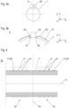
- FIG 4 a manufacturing step of the inventive arrangement 10 is shown.
- an "endless" heating pipe 1 is provided carrying several heating element groups 3, 5.
- the endless heating pipe 1 is divided along a separation plane 41 into several arrangements 10 with a required length.
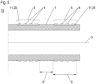
- heating element groups 3, 5 are provided on one heating pipe 1.
- the heating element groups 3, 5 are arranged at an axial distance 8 from each other, which may, for example, be at most one seventh of a width 9 of a heating element group 3, 5.
- the invention relates to a heating pipe 1 for a household appliance comprising a heating device 2, wherein the heating pipe 1 has at least one outer circumferential surface portion 10 adapted to be coated with an electrical insulation layer 11, characterized that the outer circumferential surface portion is an annular recess 24, to an arrangement comprising a heating pipe 1 and at least one heating element 4 and to a household appliance.
Landscapes
- Engineering & Computer Science (AREA)
- Physics & Mathematics (AREA)
- Thermal Sciences (AREA)
- Chemical & Material Sciences (AREA)
- Combustion & Propulsion (AREA)
- Mechanical Engineering (AREA)
- General Engineering & Computer Science (AREA)
- Resistance Heating (AREA)
Abstract
The invention relates to a heating pipe 1 for a household appliance comprising a heating device 2, wherein the heating pipe 1 has at least one outer circumferential surface portion adapted to be coated with an electrical insulation layer 11, characterized that the outer circumferential surface portion is an annular recess 24, to an arrangement comprising a heating pipe 1 and at least one heating element 4 and to a household appliance.
Description
- The present invention relates to a heating pipe for a household appliance comprising an electrical heating device according to the preamble of claim 1, to an arrangement for a household appliance comprising a heating pipe and an electrical heating device, and to a household appliance.
- According to heating pipes for household appliances having an electrical heating device in order to heat up water running through the heating pipe for cleaning purposes, the heating pipe has a constant outer circumferential surface. The heating device has a plurality of ring-shaped heating elements which are spaced apart from each other. In order to avoid any electrical short circuit between the heating elements and the heating pipe, the outer circumferential surface is coated over its entire length with an electrical insulation layer. An exemplary household appliance is a dishwasher or a washing machine.
- It has been recognized that the insulation layer tends to instable behavior which results in cracks, delamination or a reduction of its electrical resistance. In order to avoid these disadvantages, additional process steps are necessary such as providing and adhesion layer or a brushing of the outer circumferential surface of the heating pipe before applying the insulation layer.
- Therefore, the object of the present invention is to create a heating pipe for a household appliance comprising an electrical heating device, which can be produced in higher quality, an arrangement for a household appliance comprising a heating pipe and at least one electrical heating device, and an improved household appliance.
- This object is solved by a heating pipe with the features of claim 1, by an arrangement with the features of claim 5 and by a household appliance with the features of claim 15. Advantageous embodiments of the invention are mentioned in the claims.
- According to the invention, a heating pipe for a household appliance comprising an electrical heating device has least one outer circumferential surface portion which is adapted to be coated with an electrical insulation layer. Thereby, the outer circumferential surface portion is an annular recess, such as a groove surrounding the heating pipe.
- Due to the pipe surface (shape) modification, the insulation layer shows a reduced residue stress profile and shear stress profile. Additionally, the adhesion of the insulation is improved. Regarding manufacturing, for instance, neither a brushing is necessary before applying the insulation layer, nor an adhesive layer. Further on, cutting of the heating pipe is easier, as the insulation layer needs not to be cut as well. This prevents possible short circuits. In comparison, conventional prefabricated heating pipes are provided with a continuous coating that is used for insulation, so that when these prefabricated pipes are cut to size, the coating for insulation is also separated and this can cause possible short circuits, especially at the connection ends of the cut heating pipe. Over all, the heating pipe according to the invention can be manufactured risk reduced. An exemplary household appliance in which the heating pipe is used is a dish washer or a washing machine. The heating pipe may have a cylindrical shape and may be used to heat water within a household appliance. Preferably, the heating pipe is made of steel. Steel allows an effective transfer of the heat generated by the heating device to the inside of the heating pipe to heat the water running inside.
- Advantageously, the at least one annular recess is limited in axial direction by two side walls which are inclined in opposite directions to each other. If the side walls are inclined to each other, it is preferred, if in a side view, the annular recess has a V-like grooves shape or a U-like grooves shape. Thus, it is preferred, if the side walls are running away from each other in radial outwards direction. This inclined shape reduces cracks and delamination which results in improved adhesion of the insulation layer.
- Preferably, the side walls are inclined in axial direction in an angle between 25 and 45 degrees, preferably between 25 and 35 degrees, more preferably 30 degrees to each other.
- According to the invention, an arrangement for a household appliance comprising a heating pipe having at least one annular recess and at least one electrical heating device having at least one ring-shaped heating element. In the at least one annular recess, an electrical insulation layer is provided between a bottom of the at least one annular recess and the at least one heating element.
- The electrical insulation layer between the heating pipe and the electrical heating element insulates the electrically operated heating element from the electrically conductive heating pipe so that short circuits are prevented. Exemplary, the insulation layer is a ceramic layer, for instance made of Al2O3. The insulation layer can be sprayed directly in the annular recess. Adhesion of the insulation can be further improved if the annular recess is cold plasma activated before.
- The heating device includes the at least one electrical heating element, which is supplied with electricity to generate the desired heat. The heating element may be connected to a power source by means of at least one electrically conductive trace, wherein the conductive trace may be attached to a surface of the heating pipe and may be insulated with the insulation layer.
- Preferably, in one area of the at least one annular recess the insulation layer is not provided. In this uncovered area, at least on electrical connector for the at least one heating element can be positioned.
- Advantageously, the insulation-free uncovered area is delimited by two inclined surfaces facing each other. An angle between 25 and 45 degrees, preferably between 25 and 35 degrees, more preferably an angle of 30 degrees to each other is preferred.
- In one embodiment, the at least one annular recess is filled at least partially with the radially inner insulating layer and a radially outer sealing layer. The sealing layer surrounds the insulation layer over its entire circumferential extension and entire axial extension. The sealing acts as an impregnation of the insulation layer. Preferably, the sealing layer is applied directly on the insulation layer after the insulation layer has been coated. By means of this, there is no influence of air humidity, open pores in the insulation layer can be filled and a higher resistance and resilience in following process steps of the insulation layer can be achieved.
- Preferably, the sealing layer is flush with the adjacent circumferential surfaces of the heating pipe. The sealing acts as an impregnation of the insulation layer. Preferably, the sealing layer is applied directly on the insulation layer after the insulation layer has been coated. By means of this, there is no influence of air humidity, open pores in the insulation layer can be filled and a higher resistance and resilience in following process steps of the insulation layer can be achieved.
- Advantageously, the sealing layer contains phosphate. By means of this, "phosphates" can be created inside the ceramic insulation layer.
- Advantageously, the at least one heating element is positioned in axial distances to the adjacent circumferential surfaces of the heating pipe. By means of this, any electrical contact between the heating element and the adjacent outer circumferential surface is prevented. For instance, the electrical insulation layer at the two ends is larger in size than the heating device arranged thereon, so that electrical contact, for example due to water drops or moisture, between the heating elements and the adjacent outer circumferential surfaces of the heating pipe and thus short circuits are prevented. Preferable the heating device comprises several heating elements, which form a heating element group and are preferably arranged at regular distances from each other. This ensures an evenly distributed heating power through evenly distributed heating elements.
- Preferably, the at least on heating element is coated on the sealing layer directly as a ring. By means of this, the heating element is linked with the sealing layer directly. A preferred material for the heating element is a NiCr-alloy. The material NiCr is particularly suitable for effectively converting the electrical energy into thermal energy due to the high electrical resistance of this material. Other suitable materials are, for example, NiO + Fe3O4, TiO2, TiO2 + NiCr, AI2O3 +NiCr, Al2O3 with W, Mo, Cu or Ni; ZrO2 + Y2O3 with Ni or W.
- In one embodiment, the conductive traces of the heating elements are connected in parallel. By means of this, the resistance can be reduced. Each heating element can have a single conductive trace. Alternative, one conductive tracer is assigned to several heating elements, whereby adjacent conductive traces are then connected in parallel.
- In an alternative embodiment, the conductive traces of the heating elements are connected in serial.
- A household appliance according to the invention comprises an arrangement that has a heating pipe having at least one annular recess and at least one electrical heating device having at least one ring-shaped heating element. In the at least one annular recess, an electrical insulation layer is provided between a bottom of the at least one annular recess and the heating device. Such household appliance can be produced in a higher quality and shows a high resistance against electrical short circuits. Exemplary household appliances are dishwashers and washing machines.
- In order to enhance the area in which the water running through the heating pipe can be heated, a plurality of annular recesses is provided. The annular recesses are spaced apart from each other in axial direction, preferably in a regular distance. Heating pipe surface that are adjacent to the annular recesses, i. e. surface areas of the heating pipe between adjacent annular recesses, do not need to be prepared in particular, as in these surface areas the insulation material is not provided. These surface areas can keep their initial outer diameter.
- In what follows, preferred embodiments of the present invention are explained with respect to the accompanying drawings. As is to be understood, the various elements and components are depicted as examples only, and they may be facultative and/or combined in a manner different than that depicted. Reference signs for related elements are used comprehensively and not defined again for each figure.
- Fig. 1
- schematic representation of an inventive heating pipe carrying heating elements of a heating device in a side view;
- Fig. 2
- section of
figure 1 ; - Fig. 3a
- the heating pipe shown in
figures 1 and 2 in a front view; - Fig. 3b
- a detail of the
figure 3a ; - Fig. 4
- a manufacturing step of the heating pipe in a side view; and
- Fig. 5
- a schematic representation of another embodiment of an inventive heating pipe in a side view
- Terms used in the specification such as "axial" and "radial" are referred to the longitudinal axis x of a heating pipe 1, which preferably has a cylindrical shape.
-
Figure 1 shows a schematic representation of an axial section of aninventive arrangement 10 comprising a heating pipe andheating elements 4 of a heating device. Thearrangement 10 can be installed in a household appliance such as a dish washer or a washing machine in order to heat cold water running through the heating pipe 1 for washing (cleaning) purposes. - The heating device comprises a first annular
heating element group 3 consisting of four ring-shapedheating elements 4, for instance. - The heating element groups 3surrounds the heating pipe 1. Between the
heating elements 4 and the heating pipe 1 a layer-composition Figure 2 . - The
heating elements 4 of theheating element group 3 is arranged at a fixedaxial distance 6 from each other, which may, for example, be at least one seventh of a width 7 (extension in axial direction of the heating pipe 1) of anindividual heating element 4. Theheating elements 4 themselves have a strips-like shape and are put around the layer-composition Figure 3b , theheating elements 4 are formed as an opened ring having two ends spaced apart and facing each other. -
Figure 2 shows a section ofFigure 1 with a singleheating element group 3 with fourheating elements 4 exemplary for all heating element groups 5 provided on the heating pipe 1. - As illustrated, the
heating element group 3 is positioned in a groove-shaped area of the heating pipe 1. In particular, the annularheating element group 3 is arranged on a layer-composition annular recess 24 of the heating pipe 1, wherein eachheating element 4 is coated directly on the radiallyouter layer 20. - The
annular recess 24 is provided on the outer side of the heating pipe 1. Theannular recess 24 has twoinclined side walls annular recess 24 in axial direction (longitudinal direction of the heating pipe 1). Theside walls angle 23 of 30 degrees each in axial direction. - The
annular recess 24 in the heating pipe 1 is filled with a radially innerelectrical insulation layer 11, for example of Al2O3, and with a radiallyouter sealing layer 20, for instance of phosphate. However, as explained with reference toFigures 3a and 3b , onearea 33 of theannular recess 24 is uncovered. Thelayers annular recess 24 that the outer circumferential surface of thesealing layer 20 is coaxial with adjacent outercircumferential surfaces 25 of the heating pipe 1. Theinsulation layer 11 has a greater radial extension than thesealing layer 20. The axial end sides of theinsulation layer 11 and of thesealing layer 20 are inclined to each other according to theside walls annular recess 4 in the same angle, which is preferably (but not limited to) 30 degrees. - The
sealing layer 20 terminates at afirst end 26 of theannular recess 24 at a first distance 27 from afirst end 28 of theheating element group 4 comprise therespective heating elements 4 in other axial direction, thesealing layer 20 terminats at an oppositesecond end 29 of theannular recess 24 at asecond distance 30 from asecond end 31 of theheating element group 4. Thedistances 27, 30 are at least one sixth of the width 7 of aheating element 4, such that a sufficient distance is thereby ensured to prevent a short circuit. - As can be seen in
Figures 3a and 3b , theinsulation layer 11 and thus thesealing layer 20 are interrupted in circumferential direction. Thus, theinsulation layer 11 and thesealing layer 20 are opened rings in circumferential direction. Thus, an uncoveredarea 33 of theannular recess 33 is provided. The uncovered are 33 can extend over the entire length of theannular recess 24. Alternatively, a plurality of uncoveredareas 33 are provided, which are spaced apart from each other by strips of the layer-composition 11, 20 (not shown). In this case, each uncoveredarea 33 would be prepared for one electrical component such as a connector. - What is also shown in
Figures 3a and 3b is that theheating elements 4 are also "opened rings". They have a strips-like shape and are positioned on thesealing layer 20 in such a way that their opposite ends are positioned in a distance to the uncoveredarea 33. The uncoveredarea 33 has such a size an electrical component such as anelectrical connector 35 can be positioned in it. - The uncovered
area 33 is delimited in circumferential direction by twosurfaces insulation layer 11 is covered entirely with thesealing layer 20, theseinclined surfaces sealing layer 20. Similar to theside walls inclined surfaces - In
Figure 4 , a manufacturing step of theinventive arrangement 10 is shown. According toFigure 4 , an "endless" heating pipe 1 is provided carrying severalheating element groups 3, 5. In a pipe zone between the adjacentheating element groups 3, 5 and thus in a pipe zone which is free of any layer-composition separation plane 41 intoseveral arrangements 10 with a required length. - As illustrated in
Figure 5 , in one embodiment severalheating element groups 3, 5 are provided on one heating pipe 1. Theheating element groups 3, 5 are arranged at an axial distance 8 from each other, which may, for example, be at most one seventh of a width 9 of aheating element group 3, 5. - The invention relates to a heating pipe 1 for a household appliance comprising a heating device 2, wherein the heating pipe 1 has at least one outer
circumferential surface portion 10 adapted to be coated with anelectrical insulation layer 11, characterized that the outer circumferential surface portion is anannular recess 24, to an arrangement comprising a heating pipe 1 and at least oneheating element 4 and to a household appliance. -
- 1
- heating pipe
- 3
- heating element group
- 4
- heating element
- 5
- heating element group
- 6
- axial distance between adjacent heating elements
- 7
- width of a heating element
- 8
- axial distance between adjacent heating element groups
- 9
- width of heating element group
- 10
- arrangement
- 11
- insulation layer
- 20
- sealing layer
- 21
- side wall
- 22
- side wall
- 23
- angle
- 24
- annular recess
- 25
- outer circumferential surfaces
- 26
- first end of annular recess
- 27
- first distance
- 28
- first end of heating element
- 29
- second end of annular recess
- 30
- second distance
- 31
- second end of heating element
- 33
- uncovered area
- 35
- connector
- 37
- inclined surface
- 39
- inclined surface
- 41
- separation plane
- x
- axial / longitudinal axis of the heating pipe
Claims (15)
- Heating pipe (1) for a household appliance comprising an electrical heating device (3, 5), wherein the heating pipe (1) has at least one outer circumferential surface portion adapted to be coated with an electrical insulation layer (11), characterized that the outer circumferential surface portion is an annular recess (24).
- Heating pipe (1) according to claim 1, wherein the at least one annular recess (24) is limited in axial direction by two side walls (21, 22) which are inclined in opposite directions to each other.
- Heating pipe (1) according to claim 2, wherein the side walls (20, 21) are inclined in an angel (23) between 25 degrees and 45 degrees each in axial direction.
- Heating pipe (1) according to any of the preceding claims, wherein a plurality of annular recesses (24) is provided which are spaced apart from each other in axial direction.
- Arrangement (10) for a household appliance, comprising a heating pipe (1) according to one of the preceding claims having at least one annual recess (24) and at least one electrical heating device (3, 5) having at least one ring-shaped heating element (4), wherein an electrical insulation layer (11) is provided between a bottom of the at least one annular recess (24) and the heating device (4, 5).
- Arrangement (10) according to claim 5, wherein in one area (33) of the at least one annular recess (24) the insulation layer (11) is not provided.
- Arrangement (10) according to claim 6, wherein in circumferential direction the uncovered area is delimited by two inclined surfaces (37, 39) facing each other.
- Arrangement (10) according to claims 5, 6 or 7, wherein a sealing layer (20) surrounds the insulation layer (11) over its entire circumferential and axial extension.
- Arrangement (10) according to claim 8, wherein the sealing layer (20) is flush with adjacent circumferential surfaces (25) of the heating pipe (1).
- Arrangement (10) according to claim 8 or 9, wherein the sealing layer (20) contains phosphate.
- Arrangement (10) according to any of the preceding claims 5 to 10, wherein the at least one heating element (4) is positioned in axial distances (26, 28) to the adjacent outer circumferential surfaces (25) of the heating pipe (1).
- Arrangement (10) according to any of the preceding claims 5 to 11, wherein the at least on heating element (4) is coated on the sealing layer (20) directly in a ring shape.
- Arrangement (10) according to any of the preceding claims 5 to 12, wherein the heating elements (4, 5) are connected via electrically conductive in parallel.
- Arrangement (10) according to any of the preceding claims 5 to 12, wherein the heating elements (4, 5) are connected via electrically conductive in serial.
- Household appliance comprising an arrangement (10) according to any of the claims 5 to 13.
Priority Applications (1)
| Application Number | Priority Date | Filing Date | Title |
|---|---|---|---|
| EP23176198.2A EP4472353A1 (en) | 2023-05-30 | 2023-05-30 | Heating pipe for a household apliance |
Applications Claiming Priority (1)
| Application Number | Priority Date | Filing Date | Title |
|---|---|---|---|
| EP23176198.2A EP4472353A1 (en) | 2023-05-30 | 2023-05-30 | Heating pipe for a household apliance |
Publications (1)
| Publication Number | Publication Date |
|---|---|
| EP4472353A1 true EP4472353A1 (en) | 2024-12-04 |
Family
ID=86609688
Family Applications (1)
| Application Number | Title | Priority Date | Filing Date |
|---|---|---|---|
| EP23176198.2A Pending EP4472353A1 (en) | 2023-05-30 | 2023-05-30 | Heating pipe for a household apliance |
Country Status (1)
| Country | Link |
|---|---|
| EP (1) | EP4472353A1 (en) |
Citations (5)
| Publication number | Priority date | Publication date | Assignee | Title |
|---|---|---|---|---|
| GB174895A (en) * | 1921-02-01 | 1922-04-27 | Alfred Beschorner | Improvements in and relating to liquid heaters |
| US4192988A (en) * | 1977-07-11 | 1980-03-11 | Foto-Mark, Inc. | Electrically heated thermal microbial drain barrier |
| DE3720927C1 (en) * | 1987-06-25 | 1988-12-01 | Licentia Gmbh | Electrically heated continuous-flow heater for washing machines or dishwashers |
| WO2009064862A1 (en) * | 2007-11-16 | 2009-05-22 | Watlow Electric Manufacturing Company | Moisture resistant layered sleeve heater and method of manufacture thereof |
| DE202012012960U1 (en) * | 2012-01-05 | 2014-11-17 | BSH Bosch und Siemens Hausgeräte GmbH | Heating device in a water-conducting household appliance |
-
2023
- 2023-05-30 EP EP23176198.2A patent/EP4472353A1/en active Pending
Patent Citations (5)
| Publication number | Priority date | Publication date | Assignee | Title |
|---|---|---|---|---|
| GB174895A (en) * | 1921-02-01 | 1922-04-27 | Alfred Beschorner | Improvements in and relating to liquid heaters |
| US4192988A (en) * | 1977-07-11 | 1980-03-11 | Foto-Mark, Inc. | Electrically heated thermal microbial drain barrier |
| DE3720927C1 (en) * | 1987-06-25 | 1988-12-01 | Licentia Gmbh | Electrically heated continuous-flow heater for washing machines or dishwashers |
| WO2009064862A1 (en) * | 2007-11-16 | 2009-05-22 | Watlow Electric Manufacturing Company | Moisture resistant layered sleeve heater and method of manufacture thereof |
| DE202012012960U1 (en) * | 2012-01-05 | 2014-11-17 | BSH Bosch und Siemens Hausgeräte GmbH | Heating device in a water-conducting household appliance |
Similar Documents
| Publication | Publication Date | Title |
|---|---|---|
| US11191129B2 (en) | Layered heater system having conductive overlays | |
| CN1918945B (en) | Combination material layering process for electric heater | |
| EP1283327B1 (en) | Method for enhancing heat transfer inside a turbulated cooling passage | |
| US4581521A (en) | Electrically heated pipe assembly | |
| US8481902B2 (en) | Heating element production | |
| CA2626263C (en) | Hot runner nozzle heater and methods of manufacture thereof | |
| CA2719410C (en) | Moisture resistant layered sleeve heater and method of manufacture thereof | |
| CN112166541A (en) | Stator with insulation | |
| US6921882B2 (en) | Ceramic cooktop | |
| US5491373A (en) | Commutators | |
| EP0057046B1 (en) | Sliding contact assemblies for rotary electric machines | |
| US2471808A (en) | Collector ring assembly | |
| US11466371B2 (en) | Anode assembly with reduced attenuation properties for cathodic protection systems | |
| CN108187996A (en) | A kind of composite transducer | |
| US10952284B2 (en) | Heating cable | |
| KR20060103511A (en) | Commutator for electric machine | |
| CN111403595B (en) | Preparation method of piezoelectric ceramic multi-actuation wall structure | |
| US9954333B2 (en) | Method of forming a commutator | |
| CN211208007U (en) | High-temperature-resistant 200-grade enameled wire | |
| US20190364619A1 (en) | Method for the production of a heating device and heating device produced thereby | |
| CN221633510U (en) | Slot insulating paper, stator and motor | |
| US20240106178A1 (en) | Slip ring module | |
| CN105626033B (en) | Lateral electrode assembly of petroleum logging tool and manufacturing method thereof | |
| KR200341346Y1 (en) | Heating cable | |
| CN107887769B (en) | Carbon deposition and cold welding prevention commutator |
Legal Events
| Date | Code | Title | Description |
|---|---|---|---|
| PUAI | Public reference made under article 153(3) epc to a published international application that has entered the european phase |
Free format text: ORIGINAL CODE: 0009012 |
|
| STAA | Information on the status of an ep patent application or granted ep patent |
Free format text: STATUS: THE APPLICATION HAS BEEN PUBLISHED |
|
| AK | Designated contracting states |
Kind code of ref document: A1 Designated state(s): AL AT BE BG CH CY CZ DE DK EE ES FI FR GB GR HR HU IE IS IT LI LT LU LV MC ME MK MT NL NO PL PT RO RS SE SI SK SM TR |
|
| STAA | Information on the status of an ep patent application or granted ep patent |
Free format text: STATUS: REQUEST FOR EXAMINATION WAS MADE |
|
| 17P | Request for examination filed |
Effective date: 20250604 |