EP4472344A2 - Systeme und verfahren für strömungssteuerungsoptimierungen einer verteilten einheit oder zentralisierten einheit für stark skalierbare zellulare systeme - Google Patents
Systeme und verfahren für strömungssteuerungsoptimierungen einer verteilten einheit oder zentralisierten einheit für stark skalierbare zellulare systeme Download PDFInfo
- Publication number
- EP4472344A2 EP4472344A2 EP24174884.7A EP24174884A EP4472344A2 EP 4472344 A2 EP4472344 A2 EP 4472344A2 EP 24174884 A EP24174884 A EP 24174884A EP 4472344 A2 EP4472344 A2 EP 4472344A2
- Authority
- EP
- European Patent Office
- Prior art keywords
- drbs
- drb
- ddds
- buffer
- pdu
- Prior art date
- Legal status (The legal status is an assumption and is not a legal conclusion. Google has not performed a legal analysis and makes no representation as to the accuracy of the status listed.)
- Pending
Links
- 238000000034 method Methods 0.000 title claims abstract description 44
- 238000005457 optimization Methods 0.000 title abstract description 11
- 230000001413 cellular effect Effects 0.000 title abstract description 5
- 239000000872 buffer Substances 0.000 claims abstract description 118
- 238000007726 management method Methods 0.000 claims abstract description 67
- 238000012384 transportation and delivery Methods 0.000 claims abstract description 15
- 230000003247 decreasing effect Effects 0.000 claims abstract description 4
- 230000015654 memory Effects 0.000 claims description 60
- 230000005540 biological transmission Effects 0.000 claims description 23
- 230000008859 change Effects 0.000 claims description 3
- 238000005192 partition Methods 0.000 claims description 3
- 230000006870 function Effects 0.000 description 29
- 238000012545 processing Methods 0.000 description 18
- 238000004891 communication Methods 0.000 description 11
- 238000003860 storage Methods 0.000 description 8
- 230000007246 mechanism Effects 0.000 description 7
- 230000008569 process Effects 0.000 description 7
- 230000006978 adaptation Effects 0.000 description 6
- 239000013256 coordination polymer Substances 0.000 description 5
- 238000005516 engineering process Methods 0.000 description 5
- 230000002829 reductive effect Effects 0.000 description 5
- 230000003068 static effect Effects 0.000 description 5
- 238000004590 computer program Methods 0.000 description 4
- 230000009977 dual effect Effects 0.000 description 4
- 238000013461 design Methods 0.000 description 3
- 230000000737 periodic effect Effects 0.000 description 3
- 238000000926 separation method Methods 0.000 description 3
- 230000008901 benefit Effects 0.000 description 2
- 238000010586 diagram Methods 0.000 description 2
- 230000013016 learning Effects 0.000 description 2
- 238000013507 mapping Methods 0.000 description 2
- 230000011664 signaling Effects 0.000 description 2
- 101000741965 Homo sapiens Inactive tyrosine-protein kinase PRAG1 Proteins 0.000 description 1
- 101001018494 Homo sapiens Pro-MCH Proteins 0.000 description 1
- 102100038659 Inactive tyrosine-protein kinase PRAG1 Human genes 0.000 description 1
- 102100033721 Pro-MCH Human genes 0.000 description 1
- 239000000654 additive Substances 0.000 description 1
- 230000000996 additive effect Effects 0.000 description 1
- 125000004122 cyclic group Chemical group 0.000 description 1
- 230000003111 delayed effect Effects 0.000 description 1
- 230000001419 dependent effect Effects 0.000 description 1
- 238000009826 distribution Methods 0.000 description 1
- 238000001914 filtration Methods 0.000 description 1
- 230000000670 limiting effect Effects 0.000 description 1
- 230000014759 maintenance of location Effects 0.000 description 1
- 238000004519 manufacturing process Methods 0.000 description 1
- 230000003287 optical effect Effects 0.000 description 1
- 238000013468 resource allocation Methods 0.000 description 1
- 230000000717 retained effect Effects 0.000 description 1
- 239000004984 smart glass Substances 0.000 description 1
- 238000000638 solvent extraction Methods 0.000 description 1
- 238000012546 transfer Methods 0.000 description 1
Images


Classifications
-
- H—ELECTRICITY
- H04—ELECTRIC COMMUNICATION TECHNIQUE
- H04W—WIRELESS COMMUNICATION NETWORKS
- H04W88/00—Devices specially adapted for wireless communication networks, e.g. terminals, base stations or access point devices
- H04W88/08—Access point devices
- H04W88/085—Access point devices with remote components
-
- H—ELECTRICITY
- H04—ELECTRIC COMMUNICATION TECHNIQUE
- H04W—WIRELESS COMMUNICATION NETWORKS
- H04W28/00—Network traffic management; Network resource management
- H04W28/02—Traffic management, e.g. flow control or congestion control
Definitions
- the present disclosure relates to systems and methods for radio access networks.
- the present disclosure relates to the design of operation, administration and management of various network elements of 4G and 5G based mobile networks.
- Conventional RANs were built employing an integrated unit where the entire RAN was processed.
- Conventional RANs implement the protocol stack (e.g., Physical Layer (PHY), Media Access Control (MAC), Radio Link Control (RLC), Packet Data Convergence Control (PDCP) layers) at the base station (also referred to as the evolved node B (eNodeB or eNB) for 4G LTE or next generation node B (gNodeB or gNB) for 5G NR.
- PHY Physical Layer
- MAC Media Access Control
- RLC Radio Link Control
- PDCP Packet Data Convergence Control
- eNodeB evolved node B
- gNodeB or gNB next generation node B
- 5G NR 5G NR.
- conventional RANs use application-specific hardware for processing, which make the conventional RANs difficult to upgrade and evolve.
- Cloud-based Radio Access Networks are networks where a significant portion of the RAN layer processing is performed at a baseband unit (BBU) located in the cloud on commercial off-the-shelf servers, while the radio frequency (RF) and real-time critical functions can be processed in the remote radio unit (RRU), also referred to as the radio unit (RU).
- BBU baseband unit
- RF radio frequency
- RRU remote radio unit
- the BBU can be split into two parts: centralized unit (CU) and distributed unit (DU). CUs are usually located in the cloud on commercial off-the-shelf servers, while DUs can be distributed.
- the BBU can also be virtualized, in which case it is also known as vBBU. Radio Frequency (RF) interface and real-time critical functions can be processed in the remote radio unit (RRU).
- RF Radio Frequency
- an interface called the fronthaul For the RRU and DU to communicate, an interface called the fronthaul is provided.
- 3rd Generation Partnership Project (3GPP) has defined 8 options for the split between the BBU and the RRU among different layers of the protocol stack. There are multiple factors affecting the selection of the fronthaul split option such as bandwidth, latency, implementation cost, virtualization benefits, complexity of the fronthaul interface, expansion flexibility, computing power, and memory requirement.
- One of the splits recently standardized by O-RAN Alliance is split option 7-2x (Intra-Physical (PHY) layer split).
- FFT Fast Fourier Transform
- CP Cyclic Prefix
- pre-filtering functions reside in the RU, while the rest of PHY functions reside in the DU.
- iFFT inverse Fast Fourier Transform
- CP addition and beamforming functions reside in the RU
- the rest of PHY functions reside in the DU.
- This split has multiple advantages such as simplicity, transport bandwidth scalability, beamforming support, interoperability, support for advanced receivers and inter-cell coordination, lower O-RU complexity, future proof-ness, interface and functions symmetry.
- the method is performed by a computer system that comprises one or more processors and a computer-readable storage medium encoded with instructions executable by at least one of the processors and operatively coupled to at least one of the processors.
- a method for a radio access network (RAN) base station comprises: selecting a subset of Data Radio Bearers (DRBs) from a set of DRBs; changing a frequency of DL Data Delivery Status (DDDS) message transmissions for the subset of DRBs; and maintaining a frequency or reducing the frequency of DDDS transmissions for remaining DRBs of the set of DRBs.
- the changing can comprise reducing the frequency of the DDDS message transmissions for the subset of DRBs; and maintaining a frequency of the DDDS transmissions for remaining DRBs of the set of DRBs.
- the changing can also comprise increasing the frequency of the DDDS message transmissions for the subset of DRBs; and maintaining a frequency or reducing the frequency of the DDDS transmissions for remaining DRBs of the set of DRBs.
- the method is implemented at a RAN Intelligent Controller (RIC) configured to identify the subset of DRBs based on parameters sent from a Distributed Unit (DU) or a Centralized Unit (CU) of the BS.
- the method can further comprise: subscribing to the parameters from a gNB or eNB E2 node by a near-RT RIC; detecting, by the E2 node, an RIC event trigger; analyzing the parameters, by the near-RT RIC, to determine whether to change a frequency of the subset of DDDS transmissions, and if so; updating the parameters at the E2 node.
- the parameters can comprise:
- the parameters can also comprise: sending output parameters from the RT RIC to the CU, the DU, or both, including: an identity of DRBs for which DDDS needs to be sent more often and a decreased time interval an identity of DRBs for which DDDS needs to be sent less often and an increased time interval; or updated buffer management pools for the subset of DRBs; or a combination of thereof.
- RAN radio access network
- BS base station
- DU Distributed Unit
- CU Centralized unit
- the method can further comprise: maintaining, by the DU, a latency condition state variable configured to indicate a high or low latency state.
- the DU can be configured to set a DDDS Protocol Data Unit (PDU) bit to indicate the latency condition when the latency is in the high condition.
- PDU Protocol Data Unit
- the method can further comprise: reducing a frequency of DDDS message transmissions for the DRB if the threshold criterion is exceeded.
- a radio access network (RAN) base station (BS) comprising a Distributed Unit (DU) and a Centralized unit (CU) comprises: configuring a 4G eNB DU to increase a frequency of DDDS messages to a CU upon finding holes in a received Packet Data Convergence Protocol (PDCP) SNs.
- RAN radio access network
- BS base station
- DU Distributed Unit
- CU Centralized unit
- a system comprises: a base station (BS) comprising a buffer management module, the buffer management module being configured to take a vector of inputs and output buffer management parameters to compute a wastage for a buffer size for each DRB and an average memory wastage across a plurality of DRBs.
- the buffer management module can further be configured to at least give the output as ( b1 , b2, ..., bK, M1, M2, ., MK ); and the vector of inputs includes:
- a memory wastage can be defined as ( b -L ) bytes, or memory utilization is defined as L / b ; and the buffer management module is configured to at least estimate the average memory wastage considering all of the plurality of DRBs.
- the buffer management module can be configured to at least estimate the average memory wastage for each buffer size separately.
- the buffer management module can be configured to at least:
- the buffer management module can be configured with a RLC SDU queue of size (RlcSduQSize) for each DRB, and calculating the maximum number of buffers for each buffer size the RlcSduQSize comprises:
- the buffer management modules can be configured with a maximum number of buffers for a DRB.
- the buffer management module can be configured with a RLC SDU queue of size (RlcSduQSize) for each DRB, and calculating the maximum number of buffers for each buffer size the RlcSduQSize comprises:
- the buffer management module can be implemented a Distributed Unit (DU) or a Centralized unit (CU).
- DU Distributed Unit
- CU Centralized unit
- the buffer management module can be connected to an RIC, and the RIC can be configured to implement actions for the buffer management module.
- RAN Radio Access Networks
- CU central unit
- DU distributed unit
- BBUs baseband units
- CUs are usually located in the cloud on commercial off-the-shelf servers, while DUs can be distributed.
- the RF and real-time critical functions can be processed in the remote radio unit (RU).
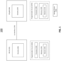
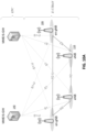
- FIG. 1 is a block diagram of a system 100 for implementations as described herein.
- System 100 includes a NR UE 101, a NR gNB 106.
- the NR UE and NR gNB 106 are communicatively coupled via a Uu interface 120.
- NR UE 101 includes electronic circuitry, namely circuitry 102, that performs operations on behalf of NR UE 101 to execute methods described herein.
- Circuity 102 can be implemented with any or all of (a) discrete electronic components, (b) firmware, and (c) a programmable circuit 102A.
- NR gNB 106 includes electronic circuitry, namely circuitry 107, that performs operations on behalf of NR gNB 106 to execute methods described herein.
- Circuity 107 can be implemented with any or all of (a) discrete electronic components, (b) firmware, and (c) a programmable circuit 107A.
- Programmable circuit 107A which is an implementation of circuitry 107, includes a processor 108 and a memory 109.
- Processor 108 is an electronic device configured of logic circuitry that responds to and executes instructions.
- Memory 109 is a tangible, non-transitory, computer-readable storage device encoded with a computer program.
- memory 109 stores data and instructions, i.e., program code, that are readable and executable by processor 108 for controlling operations of processor 108.
- Memory 109 can be implemented in a random-access memory (RAM), a hard drive, a read only memory (ROM), or a combination thereof.
- One of the components of memory 109 is a program module, namely module 110.
- Module 110 has instructions for controlling processor 108 to execute operations described herein on behalf of NR gNB 106.
- module is used herein to denote a functional operation that can be embodied either as a stand-alone component or as an integrated configuration of a plurality of subordinate components.
- each of module 105 and 110 can be implemented as a single module or as a plurality of modules that operate in cooperation with one another.
- Storage device 130 is a tangible, non-transitory, computer-readable storage device that stores module 110 thereon.
- Examples of storage device 130 include (a) a compact disk, (b) a magnetic tape, (c) a read only memory, (d) an optical storage medium, (e) a hard drive, (f) a memory unit consisting of multiple parallel hard drives, (g) a universal serial bus (USB) flash drive, (h) a random-access memory, and (i) an electronic storage device coupled to NR gNB 106 via a data communications network.
- Uu Interface (120) is the radio link between the NR UE and NR gNB, which is compliant to the 5G NR specification.
- UEs 101 can be dispersed throughout a wireless communication network, and each UE can be stationary or mobile.
- a UE includes: an access terminal, a terminal, a mobile station, a subscriber unit, a station, and the like.
- a UE can also include be a cellular phone (e.g., a smart phone), a personal digital assistant (PDA), a wireless modem, a wireless communication device, a handheld device, a laptop computer, a cordless phone, a wireless local loop (WLL) station, a tablet, a camera, a gaming device, a drone, a robot/robotic device, a netbook, a smartbook, an ultrabook, a medical device, medical equipment, a healthcare device, a biometric sensor/device, a wearable device such as a smart watch, smart clothing, smart glasses, a smart wristband, and/or smart jewelry (e.g., a smart ring, a smart bracelet, and the like), an entertainment device (e.g.,
- UEs can include UEs considered as machine-type communication (MTC) UEs or enhanced/evolved MTC (eMTC) UEs.
- MTC/eMTC UEs that can be implemented as loT UEs.
- IoT UEs include, for example, robots/robotic devices, drones, remote devices, sensors, meters, monitors, cameras, location tags, and the like, that can communicate with a BS, another device (e.g., remote device), or some other entity.
- a wireless node can provide, for example, connectivity for or to a network (e.g., a wide area network such as Internet or a cellular network) via a wired or wireless communication link.
- a network e.g., a wide area network such as Internet or a cellular network
- One or more UEs 101 in the wireless communication network can be a narrowband bandwidth UE.
- narrowband UEs devices with limited communication resources, e.g. smaller bandwidth, are considered as narrowband UEs.
- legacy devices such as legacy and/or advanced UEs can be considered as wideband UEs.
- Wideband UEs are generally understood as devices that use greater amounts of bandwidth than narrowband UEs.
- the UEs 101 are configured to connect or communicatively couple with a RAN.
- the RAN can be an NG RAN or a 5G RAN, an E-UTRAN, an MF RAN, or a legacy RAN, such as a UTRAN or GERAN.
- NG RAN or the like refers to a RAN 110 that operates in an NR or 5G system
- E-UTRAN or the like refers to a RAN that operates in an LTE or 4G system
- MF RAN refers to a RAN that operates in an MF system 100.
- the UEs 101 utilize connections (or channels), respectively, each of which comprises a physical communications interface or layer.
- the physical DL channels include the PDSCH, PMCH, PDCCH, EPDCCH, MPDCCH, R-PDCCH, SPDCCH, PBCH, PCFICH, PHICH, NPBCH, NPDCCH, NPDSCH, and/or any other physical DL channels mentioned herein.
- the physical UL channels include the PRACH, PUSCH, PUCCH, SPUCCH, NPRACH, NPUSCH, and/or any other physical UL channels mentioned herein.
- the RAN can include one or more AN nodes or RAN nodes. These access nodes can be referred to as BS, gNBs, RAN nodes, eNBs, NodeBs, RSUs, MF-APs, TRxPs or TRPs, and so forth, and comprise ground stations (e.g., terrestrial access points) or satellite stations providing coverage within a geographic area (e.g., a cell).
- NG RAN node refers to a RAN node that operates in an NR or 5G system (e.g., a gNB), and the term “E-UTRAN node” or the like refers to a RAN node that operates in an LTE or 4G system (e.g., an eNB).
- the RAN nodes can be implemented as one or more of a dedicated physical device such as a macrocell base station, and/or a low power base station for providing femtocells, picocells or other like cells having smaller coverage areas, smaller user capacity, or higher bandwidth compared to macrocells.
- all or parts of the RAN nodes can be implemented as one or more software entities running on server computers as part of a virtual network, which can be referred to as a CRAN and/or a vBBU.
- the CRAN or vBBU can implement a RAN function split, such as a PDCP split wherein RRC and PDCP layers are operated by the CRAN/vBBU and other L2 protocol entities are operated by individual RAN nodes; a MAC/PHY split where RRC, PDCP, RLC, and MAC layers are operated by the CRAN/vBBU and the PHY layer is operated by individual RAN nodes; or a "lower PHY" split where RRC, PDCP, RLC, MAC layers and upper portions of the PHY layer are operated by the CRAN/vBBU and lower portions of the PHY layer are operated by individual RAN nodes.
- a RAN function split such as a PDCP split wherein RRC and PDCP layers are operated by the CRAN/vBBU and
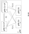
- an individual RAN node can represent individual gNB-DUs that are connected to a gNB-CU 151via individual F1 interfaces.
- the gNB-DUs can include one or more remote radio heads (RRH), and the gNB-CU 151can be operated by a server that is located in the RAN or by a server pool in a similar manner as the CRAN/vBBU.
- RRH remote radio heads
- One or more of the RAN nodes can be next generation eNBs (ng-eNBs), which are RAN nodes that provide E-UTRA user plane and control plane protocol terminations toward the UEs 101, and are connected to a 5GC via an NG interface.
- ng-eNBs next generation eNBs
- the MF-APs are entities that provide MultiFire radio services, and can be similar to eNBs in an 3GPP architecture.
- a scheduling entity e.g.: BS, gNB, eNB and the like
- a scheduling entity can be configured to schedule, assign, reconfigure, and release resources for one or more subordinate entities.
- a UE 101 (or other device) can function as master node scheduling entity, scheduling resources for one or more secondary node subordinate entities (e.g., one or more other UEs 101).
- a scheduling entity and one or more subordinate entities can communicate utilizing the scheduled resources.
- BS can be equipped with T antennas and UE 101 can be equipped with R antennas, where in general T ⁇ 1 and R ⁇ 1.
- a transmit processor is configured to receive data from a data source for one or more UEs 101 and select one or more modulation and coding schemes (MCS) for each UE based on channel quality indicators (CQIs) received from the UE 101.
- MCS modulation and coding schemes
- CQIs channel quality indicators
- the BS is configured to process (e.g., encode and modulate) the data for each UE 101 based on the MCS(s) selected for the UE 101, and provide data symbols for all UEs.
- a transmit processor is also configured to process system information (e.g., for static resource partitioning information (SRPI) and the like) and control information (e.g., CQI requests, grants, upper layer signaling, and the like) and can provide overhead symbols and control symbols.
- Processor 108 can also generate reference symbols for reference signals (e.g., the cell-specific reference signal (CRS)) and synchronization signals (e.g., the primary synchronization signal (PSS) and the secondary synchronization signal (SSS)).
- reference signals e.g., the cell-specific reference signal (CRS)
- synchronization signals e.g., the primary synchronization signal (PSS) and the secondary synchronization signal (SSS)
- a transmit (TX) multiple-input multiple-output (MIMO) processor can be configured perform spatial processing (e.g., precoding) on the data symbols, the control symbols, the overhead symbols, and/or the reference symbols, if applicable, and can be configured to provide T output symbol streams to T modulators (MODs).
- Each modulator can be configured to process a respective output symbol stream (e.g., for OFDM, etc.) to obtain an output sample stream.
- Each modulator can further be configured to process (e.g., convert to analog, amplify, filter, and upconvert) the output sample stream to obtain a downlink signal.
- T downlink signals from modulators can be transmitted via T antennas.
- 5G NR New Radio
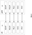
- user and control plane functions with monolithic gNB 106 are shown in the FIG.1 and FIG. 2 .
- PHY physical
- MAC Medium Access Control
- RLC Radio Link Control
- PDCP Packet Data Convergence Protocol
- SDAP Service Data Adaptation Protocol
- RRC Radio Resource Control
- PDCP Packet Data Convergence Protocol
- SDAP Service Data Adaptation Protocol
- RRC Radio Resource Control
- PDCP Packet Data Convergence Protocol
- SDAP Service Data Adaptation Protocol
- RRC Radio Resource Control
- PDCP Packet Data Convergence Protocol
- SDAP Service Data Adaptation Protocol
- NAS Non-Access Stratum
- AMF Access Mobility Function
- NG-RAN NG-Radio Access Network
- F1 is the interface between gNB-CU 151 (gNB - Centralized Unit) and gNB-DU 152 (gNB - Distributed Unit)
- NG is the interface between gNB-CU 151 (or gNB) and 5GC (5G Core)
- E1 is the interface between CU-CP (CU-Control Plane) and CU-UP (CU-User Plane)
- Xn is interface between gNBs.
- a gNB 106 can consist of a gNB-CU-CP, multiple gNB-CU-UPs and multiple gNB-DUs.
- the gNB-CU-CP is connected to the gNB-DU 152 through the F1-C interface and to the gNB-CU-UP through the E1 interface.
- the gNB-CU-UP is connected to the gNB-DU 152 through the F1-U interface and to the gNB-CU-CP through the E1 interface.
- One gNB-DU 152 is connected to only one gNB-CU-CP and one gNB-CU-UP is connected to only one gNB-CU-CP.
- FIG. 4A shows an example of an NG-RAN Architecture as described in 3GPP TS 38.501.
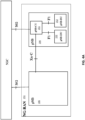
- FIG. 4B shows an example of a Separation of CU-CP (CU-Control Plane) and CU-UP (CU-User Plane) as described in 3GPP TS 38.401.
- L2 Layer 2 of 5G NR is split into the following sublayers is described in 3GPP TS 38.300):
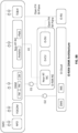
- FIG. 5 shows a DL (Downlink) Layer 2 Structure as described in 3GPP TS 38.300.
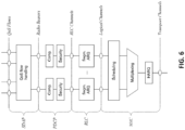
- FIG. 6 shows an UL (uplink) Layer 2 Structure in accord with 3GPP TS38.300.
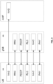
- FIG. 7 shows an L2 Data Flow example in accord with 3GPP TS 38.300 ([H] denotes headers or subheaders in FIG. 7 .)
- O-RAN which is based on disaggregated components and connected through open and standardized interfaces, is based on 3GPP NG-RAN.
- An overview of O-RAN with disaggregated RAN (CU, DU, and RU), near-real-time RIC 160 and non-real-time RIC is shown in the FIG. below.
- DU Distributed Unit
- CU Centralized Unit
- COTS Communication off-the-shelf
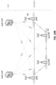
- FIGS. 8A-8B show an example of an O-RAN architecture.
- the CU and the DU are connected using the F1 interface (with F1-C for control plane and F1-U for user plane traffic) over the midhaul (MH) path.
- F1 interface with F1-C for control plane and F1-U for user plane traffic
- MH midhaul
- One DU could host multiple cells (for example, one DU could host 24 cells) and each cell can support many users.
- one cell can support 600 RRC Connected users and out of these 600, there can be 200 Active users (i.e.; users which have data to send at a given point of time).
- a cell site could include multiple sectors and each sector can support multiple cells. For example, one site could consist of three sectors and each sector could support 8 cells (with 8 cells in each sector on different frequency bands).
- One CU-CP could support multiple DUs and thus multiple cells. For example, a CU-CP could support 1000 cells and around 100,000 UEs. Each UE could support multiple DRBs and there could be multiple instances of CU-UP to serve these DRBs. For example, each UE could support 4 DRBs, and 400,000 DRBs (corresponding to 100,000 UEs) can be served by five CU-UP instances (and one CU-CP instance).
- DU can be located in a private data center or it could be located at a cell-site too.
- CU can also be located in a private data center or even hosted on a public cloud system.
- DU and CU can be tens of kilometers away.
- CU can communicate with 5G core system which could also be hosted in the same public cloud system (or could be hosted by a different cloud provider).
- RU Radio Unit
- FH fronthaul
- the E2 nodes (CU and DU) are connected to the near-real-time RIC 160 using the E2 interface.
- the E2 interface is used to send data (e.g., user, cell, slice KPMs) from the RAN, and deploy control actions and policies to the RAN at near-real-time RIC 160.
- the application or service at the near-real-time RIC 160 that deploys the control actions and policies to the RAN are called xApps.
- the near-real-time RIC 160 is connected to the non-real-time RIC 161 using the A1 interface.
- an O-RAN compliant SMO defines TE&IV, RAN NF OAM, Non-RT RIC, and NFO, FOCOM services.
- SMO interacts with O-RAN NFs with 01 interface.
- SMO interacts with O-RU with Open FH M-Plane interface and interacts O-Cloud via the O2 interface.
- O-RAN NF OAM manages O-RAN NF CM, FM, PM and creates O-RAN NF inventory and topology in TE&IV.
- FOCOM/NFO manages O-Cloud resources and creates O-Cloud resources inventory and topology in TE&IV.
- Analytics/rApp in Non-RT RIC can subscribe O-RAN NFs PM/FM, O-Cloud PM/FM data based on O-RAN NF OAM and FOCOM/NFO.
- Analytics/rApp in Non-RT RIC can retrieve the O-RAN NF and O-Cloud resource inventory and topology.
- PDU connectivity service is a service that provides exchange of PDUs between a UE and a data network identified by a Data Network Name (DNN).
- the PDU Connectivity service is supported via PDU sessions that are established upon request from the UE.
- This DNN defines the interface to a specific external data network.
- One or more QoS flows can be supported in a PDU session. All the packets belonging to a specific QoS flow have the same 5QI (5G QoS Identifier).
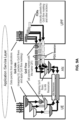
- FIG. 9A illustrates a PDU Session architecture consisting of multiple DRBs. Each DRB can consist of multiple QoS flows (3GPP TS 23.501).
- FIG. 9A illustrates a PDU Session architecture consisting of multiple DRBs. Each DRB can consist of multiple QoS flows (3GPP TS 23.501).
- FIG. 9B illustrates a flow for PDU sessions, DRBs and GTP-U Tunnels across CU and DU.
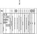
- FIG. 9C illustrates a CU and DU view on PDU session, DRBs and GTP-U tunnels for a 5G network architecture. Parts of a standard 5QI from 3GPP TS 23.501 are shown in Table 1.
- a PDU session comprises the following: A Data Radio Bearer (DRB) is between UE and CU in RAN and a NG-U GTP tunnel which is between CU and UPF (User Plane Function) in the core network.
- DRB Data Radio Bearer
- UPF User Plane Function
- the transport connection between the base station (i.e., CU-UP) and User Plane Function (UPF) uses a single GTP-U tunnel per PDU session.
- the PDU session is identified using GTP-U TEID (Tunnel Endpoint Identifier).
- the transport connection between DU and CU-UP uses a single GTP-U tunnel per DRB.
- the SDAP (Service Adaptation Protocol) Layer receives downlink data from the UPF across the NG-U interface. It maps one or more QoS Flow(s) onto a specific DRB.
- the SDAP header is present between the UE and the CU (when reflective QoS is enabled), and includes a field to identify the QoS flow in a specific PDU session.
- GTP-U protocol includes a field to identify the QoS flow and is present between CU and UPF (in the core network).
- NR UP NR User Plane
- DBS Desired Buffer Size
- DDR Desired Data Rate
- the E-UTRAN comprises a number of eNBs 116 that provide the E-UTRA U-plane (PDCP/RLC/MAC/PHY) and control plane (RRC) protocol terminations towards the UE.
- the eNBs 116 are interconnected with each other by the X2 interface.
- the eNBs 116 are also connected by the S1 interface to the EPC (Evolved Packet Core) 140, more specifically to the MME (Mobility Management Entity) by the S1-MME interface and to the Serving Gateway (S-GW) by the S1-U interface.
- EPC Evolved Packet Core
- MME Mobility Management Entity
- S-GW Serving Gateway
- E-UTRAN also supports MR-DC via E-UTRA-NR Dual Connectivity (EN-DC), in which a UE is connected to an eNB that acts as a MN and an en-gNB 106 that acts as a SN.
- EN-DC E-UTRA-NR Dual Connectivity
- the eNB 116 is connected to the EPC 140 via the S1 interface and to the en-gNB 106 via the X2 interface.
- the en-gNB 106 can also be connected to the EPC 140 via the S1-U interface and other en-gNBs 106 via the X2-U interface.
- EN-DC and en-gNB 106 comprises gNB-CU 151and gNB-DU(s) 152.
- an NG-RAN node is either:
- the gNBs 106 and ng-eNBs 116 are interconnected with each other by the Xn interface.
- the gNBs 106 and ng-eNBs 116 are also connected by the NG interfaces to the 5GC, more specifically to the AMF (Access and Mobility Management Function) by the NG-C interface and to the UPF (User Plane Function) by means of the NG-U interface.
- AMF Access and Mobility Management Function
- UPF User Plane Function
- the gNB 106 and ng-eNB host functions such as functions for Radio Resource Management: Radio Bearer Control, Radio Admission Control, Connection Mobility Control, Dynamic allocation of resources to UEs in both uplink and downlink (scheduling), connection setup and release; session Management; QoS Flow management and mapping to data radio bearers; Dual Connectivity.
- Radio Bearer Control Radio Admission Control
- Connection Mobility Control Dynamic allocation of resources to UEs in both uplink and downlink (scheduling), connection setup and release
- session Management QoS Flow management and mapping to data radio bearers; Dual Connectivity.
- control information e.g., scheduling information
- the UE can monitor different bundle sizes for the control channel depending on the maximum number of repetitions.
- O-RAN is based on disaggregated components and connected through open and standardized interfaces is based on 3GPP LTE and NR RAN.
- gNB functionality is distributed into logical nodes CU-CP, CU-UP, DU and RU.
- DU and CU are connected through F1 interface.
- E1 interface connects CU-CP and CU-UP.
- the control plane interface F1-C is defined between CU-CP and DU and the user plane interface F1-U is defined between CU-UP and DU. Procedures and functionality of F1-U interface is defined in 3GPP TS 38.425.
- F1-U interface supports NR User Plane (NR UP) protocol which, among other things, provides support for flow control and reliability between CU-UP and DU.
- Communication over F1-U interface is achieved through exchange of three PDU types (or, messages): Downlink User Data (DUD) PDU from CU-UP to DU, Downlink Data Delivery Status (DDDS) PDU from DU to CU-UP, and Transfer of Assistance Information (TAI) PDU from DU to CU-UP.
- DMD Downlink User Data
- DDDS Downlink Data Delivery Status
- TAI Transfer of Assistance Information
- the node hosting the NR PDCP is the CU-UP and the corresponding node is the DU.
- FIG. 11 shows DL User data (i.e. PDCP PDUs) from CU-UP to RLC SDU queues at the DU (corresponding node).
- PDCP PDUs DL User data
- FIG. 12 shows DL Data Delivery Status (DDDS) - Flow Control Feedback from DU to CU-UP (for each DRB).
- DDDS DL Data Delivery Status
- FIG. 13 shows Radio Assistance Information from DU (corresponding node) to CU-UP.
- FIG. 14 shows DL Data Delivery Status (DDDS) from the corresponding node (DU) to the node hosting NR PDCP (i.e. CU-UP here) for each DRB.
- DDDS DL Data Delivery Status
- the DDDS message conveys Desired Buffer Size (DBS) in bytes and Desired Data Rate (DDR) in units of bytes/second to the CU-UP. It is up to implementation to come up with the mechanism to compute DBS and DDR and choose the frequency at which this information is conveyed by the DU (to the CU-UP) If value of the DBS is zero for a DRB, the NR PDCP hosting node (i.e. the CU-UP here) shall stop sending data for that DRB from the CU-UP to the DU. If value of the DBS is greater than zero, the NR PDCP hosting node (i.e.: CU-UP) can send up to this amount of data for that DRB. The value of DDR is the amount of data desired to be received every second by the DU (from CU-UP) for that DRB.
- DBS Desired Buffer Size
- DDR Desired Data Rate
- DU can be configured to send DDDS message carrying Desired Buffer Size (DBS) field frequently. While sending DBS frequently helps to maintain the throughput, it needs DU CPU processing power in running algorithms to compute DBS and forming the DDDS message. CPU gets stretched beyond its capacity when the DU begins to support a large number of DRBs. CU-UP also needs to process these messages frequently from DU and its processing requirements also increase as number of DRBs increase in the system. As a result, CPU becomes less available to serve other important tasks that affect the system performance. Thus, DU and CU need to implement techniques to maintain system scalability and at the same time, provide efficient CU-DU flow control, in the face of overload conditions.
- DBS Desired Buffer Size
- PDCP layer (at CU-UP) performs reordering to provide in-sequence delivery while in 4G systems, reordering of RLC PDUs is done in RLC (for AM and UM mode) at DU to provide in-sequence delivery of PDCP PDUs. Due to this, flow control as used in 5G system is not really optimal for 4G systems. Disclosed is a method to optimize this for 4G systems.
- CU and DU For highly scalable systems, performance of CU and DU is limited by two resources: memory and CPU. It is also heavily dependent on the design of flow control mechanisms.
- typical base station systems usually partition the available memory into a fixed number of pools each consisting of fixed number of fixed-sized buffers.
- a memory buffer is simply a collection of bytes.
- a buffer (e.g. for RLC SDU queues in DU) is typically not shared between two PDUs. While allocating memory, a PDU should ideally be assigned a buffer whose size is closer to the PDU length.
- LC Logical Channel
- DRB Data Radio Bearer
- a fixed memory configuration can be deployed and retained throughout the functioning of the network function. For example, available memory can be partitioned into a fixed number of memory pools with each pool consisting fixed number of buffers of a given size.
- This type of static arrangement can help to keep processing requirements of the NF quite low, but it can easily reduce the number of logical channels (or data radio bearers) that one can support with a given amount of memory.
- this memory allocation can be made totally dynamic which helps to support higher number of LCs (or DRBs) but increases processing requirement in the NF.
- triggers and frequency of sending DDDS from DU to CU-UP conventionally, for RLC AM, one can define more than one trigger to send DDDS message.
- Reception of status PDU from the peer RLC entity could be one trigger because it triggers removal of those RLC PDUs from the queue which are known to have been received at the UE.
- reception of status PDU may be delayed sometimes owing to bad UL radio channel conditions in which case DU can send DDDS message at regular intervals of time.
- DU can trigger DDDS message transmission when periodic timer expires or status PDU is received (from UE), whichever happens first.
- NF For buffer management at a NF (where NF could be DU or CU in this case) in O-RAN Systems, usually static methods have been used to keep processing overhead low as described in the previous section. Packet sizes used for each buffer pool are usually configured via a config management system. One can also use full-fledged dynamic memory management system for allocating buffer for incoming packets but that increases overhead of the system. It would be advantageous to have implementations as described herein to help improve CU-DU flow control performance.
- DBS information indirectly reflects the radio channel condition as seen by the UE.
- DU sends DDDS message when it receives RLC Status PDU from UE and/or periodically for RLC AM, and periodically for RLC UM.
- RLC Status PDU receives RLC Status PDU from UE and/or periodically for RLC AM, and periodically for RLC UM.
- the processing overhead due to DDDS message increases at DU as well as at CU.
- Frequency of DDDS is increased for some such DRBs and can be decreased for other DRBs if needed.
- DU Indicates this to CU-UP via the enhanced DDDS procedure and DU can use this to reduce frequency of DDDS for the corresponding DRB.
- the DU can be configured to send more frequent DDDS messages to CU-UP upon finding holes in the received PDCP SNs for 4G systems.
- PDCP layer expects RLC to provide in-sequence delivery of PDCP PDUs at the peer PDCP layer. This requires 4G DU to provide in-sequence delivery of PDCP PDUs to the RLC layer.
- 4G DU should first recover lost PDCP PDUs before it puts them in-sequence and gives to RLC for transmission over the radio interface.
- a 4G DU can be configured to trigger transmission of DDDS message immediately upon finding holes in the received PDCP SNs or upon finding certain number of PDCP SN holes in the received PDCP SNs. This helps to reduce end-to-end delay (at application level) in 4G systems. It should be noted that this implementation is advantageous when in-sequence delivery is needed from the LTE RLC entity. While optimization given in specifically for 4G systems for this implementation, all the optimizations given above are applicable for 4G systems too.
- a total memory of M bytes (available for DRBs) are partitioned into K pools where the i th pool consists of M i buffers of size b i bytes.
- the design parameters ( K, b 1 , b 2 , ..., b K , M 1 , M 2 , ..., M K ) can be configured via a configuration management system.
- a buffer management method is configured to improve scalability of base station system.
- a Buffer Management (BuffMgmt) module is configured for each NF. This BuffMgmt module can be located at DU or CU. This module takes in the vector of inputs: (a sample of PDU lengths for each DRB, total memory being made available for storing the PDUs of each DRB, 5QI of each DRB (i.e.
- FIG. 15 shows an initial round for a per-network function buffer management.
- a total memory of M bytes is partitioned into K pools, where the i th memory pool consists of M i buffers each of size b i bytes, subject to some constraints discussed earlier.
- a sample of T PDUs whose lengths are X 1 , X 2 , ..., X T at DU for a DRB is taken.
- Each of these T PDUs is assigned to a buffer whose size is closest to, and greater than or equal to the length of the PDU.
- each PDU will be assigned to a memory buffer whose size will be one of the K different values.
- K can be (much) smaller than T for some applications.
- Y i denote the i th maximum of the sample X 1 , X 2 , ..., X T . That is, Y 1 is the PDU length that occurred the maximum number of times, Y 2 is the next PDU length after Yi that occurred the maximum number of times, and so on.
- Y (1) , Y (2) , ..., Y (K) is the increasing-ordered sequence of Y 1 , Y 2 , ..., Y K .
- a number of such buffers to be M i are estimated and set it equal to Ceil( p i *M / b i )
- an operator can configure a maximum number of buffers for a DRB. For example, an operator can configure, RLC SDU queue of size, RlcSduQSize, for each DRB. To determine number of buffers of each buffer size that RlcSduQSize can comprise:
- FIG. 16 shows a semi-static (or dynamic) optimization method to support CU-DU flow control for highly scalable systems.
- implementation II-A is applicable for 5G as well as 4G systems.
- Downlink User Data (DUD) PDU of 3GPP TS 38.425 has 4 spare bits for future use (bit 3 of the first octet and bits 5, 6, and 7 of the second octet). One of these four bits can be utilized by CU-UP to trigger DU to run the buffer management compute implementation. Further, the DU can run buffer management on the reception of DUD PDU with the designated bit for buffer management set to 1.
- buffer management can be run again to help optimize system performance. Also, if average memory wastage exceeds the pre-defined threshold mem_wastage_thresh and/or memory utilization, mem_utilization_thresh, goes below a pre-defined threshold, the above-described buffer management can be run again to optimize system performance. Alternatively, another event when average buffer wastage for last n buffer sizes exceed pre-defined thresholds can be used for those categories.
- DU learns a certain number of profiles (i.e., solutions) which are most likely to become the candidate memory management solutions. With this, the number of times needed to run buffer management mechanism specified here can be reduced, and this reduces processing overhead (and also delay in the system). Instead of running the complete mechanism again, another suitable candidate can be selected from the existing available profiles for that 5QI. It should be noted that implementation IIB is applicable for 5G as well as 4G systems.
- controlling modules for implementations I and II are configured for and located at RIC.
- the E2 nodes (CU and DU) are connected to the near-real-time RIC using the E2 interface.
- the E2 interface is used to send data (e.g., user, cell, slice KPMs) from the RAN, and deploy control actions and policies to the RAN.
- the application or service at the near-real-time RIC that deploys the control actions and policies to the RAN are call xApps.
- the near-real-time RIC is connected to the non-real-time RIC using the A1 interface.
- the E2 nodes, CU and DU are connected using the F1 interface.
- the DU is also connected to RU through the FH interface.
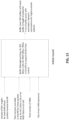
- FIG. 17 illustrates a flow for near-Real-time RIC subscribing to select parameters from DU/CU and reporting of these parameters from DU/CU to near-RT-RIC.
- near-RT-RIC 160 subscribes for these parameters from E2 nodes (i.e. DU/CU), and DU/CU REPORTs these parameters to RIC. These parameters are communicated by adding suitable fields in E2 messages.
- E2 nodes i.e. DU/CU
- These parameters are communicated by adding suitable fields in E2 messages.
- the E2 Node detects an RIC event trigger.
- the E2 Node modifies the process as described herein.
- the procedure instance at the E2 node continues.
- the E2 Node reports the RIC indication to the near-RT RIC 160.
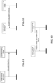
- FIG. 18 illustrates a flow for near-RT-RIC subscribing to relevant parameters from the DU 152.
- FIG. 19 illustrates a flow for near-RT-RIC subscribing to various parameters from the CU 151.
- DU/CU communicates parameters such as the following to near-real-time RIC 160:
- FIG. 20 shows a flow for near-RT-RIC 160 to help manage frequency of flow control feedback and buffer management at DU/CU.
- select parameters are sent from the DU 152 and at block 222 are sent from the CU-UP 151 to near-RT RIC 160.
- the near-RT RIC 160 sends messages to the CU-UP 151 and DU 152, including:
- Implementation III is applicable for a 5G architecture and system as well as 4G architecture and system.
- implementations and embodiments can be implemented by computer program instructions. These program instructions can be provided to a processor to produce a machine, such that the instructions, which execute on the processor, create means for implementing the actions specified herein.
- the computer program instructions can be executed by a processor to cause a series of operational steps to be performed by the processor to produce a computer-implemented process such that the instructions, which execute on the processor to provide steps for implementing the actions specified.
- some of the steps can also be performed across more than one processor, such as might arise in a multi-processor computer system or even a group of multiple computer systems.
- one or more blocks or combinations of blocks in the flowchart illustration can also be performed concurrently with other blocks or combinations of blocks, or even in a different sequence than illustrated without departing from the scope or spirit of the disclosure.
Landscapes
- Engineering & Computer Science (AREA)
- Computer Networks & Wireless Communication (AREA)
- Signal Processing (AREA)
- Mobile Radio Communication Systems (AREA)
Applications Claiming Priority (2)
| Application Number | Priority Date | Filing Date | Title |
|---|---|---|---|
| IN202321032836 | 2023-05-09 | ||
| US18/656,872 US20240381174A1 (en) | 2023-05-09 | 2024-05-07 | Systems and methods for distributed unit or centralized unit flow control optimizations for highly scalable cellular systems |
Publications (2)
| Publication Number | Publication Date |
|---|---|
| EP4472344A2 true EP4472344A2 (de) | 2024-12-04 |
| EP4472344A3 EP4472344A3 (de) | 2025-03-26 |
Family
ID=91067169
Family Applications (1)
| Application Number | Title | Priority Date | Filing Date |
|---|---|---|---|
| EP24174884.7A Pending EP4472344A3 (de) | 2023-05-09 | 2024-05-08 | Systeme und verfahren für strömungssteuerungsoptimierungen einer verteilten einheit oder zentralisierten einheit für stark skalierbare zellulare systeme |
Country Status (1)
| Country | Link |
|---|---|
| EP (1) | EP4472344A3 (de) |
Family Cites Families (5)
| Publication number | Priority date | Publication date | Assignee | Title |
|---|---|---|---|---|
| US8560696B2 (en) * | 2009-04-28 | 2013-10-15 | Intel Corporation | Transmission of advanced-MAP information elements in mobile networks |
| EP3726880A4 (de) * | 2017-12-13 | 2020-12-16 | NEC Corporation | Drahtloses kommunikationssystem, hauptbasisstation, nebenbasisstation und drahtloses kommunikationsverfahren |
| WO2020026835A1 (ja) * | 2018-08-01 | 2020-02-06 | 日本電気株式会社 | 無線局、無線通信方法、非一時的なコンピュータ可読媒体及び無線通信システム |
| JP7310324B2 (ja) * | 2019-06-06 | 2023-07-19 | 日本電気株式会社 | 無線基地局、無線通信システム、フロー制御方法及びプログラム |
| US20210314270A1 (en) * | 2020-04-01 | 2021-10-07 | Qualcomm Incorporated | Dynamic packet buffering duration |
-
2024
- 2024-05-08 EP EP24174884.7A patent/EP4472344A3/de active Pending
Also Published As
| Publication number | Publication date |
|---|---|
| EP4472344A3 (de) | 2025-03-26 |
Similar Documents
| Publication | Publication Date | Title |
|---|---|---|
| US11800592B2 (en) | Method and apparatus for supporting RLC UM mode operation in next generation mobile communication system | |
| US12089276B2 (en) | Alternate path information exchange for better scheduling and backhaul failure recovery in integrated access backhaul networks | |
| EP3295700B9 (de) | Uplink-datenaufteilung | |
| JP2022095657A (ja) | ロングタームエボリューション通信システムのためのマルチテクノロジアグリゲーションアーキテクチャ | |
| US11284461B2 (en) | Method and apparatus for controlling packet transmission for reducing latency in wireless communication system | |
| EP3873076B1 (de) | Verfahren, vorrichtung und computerprogramm zur durchführung einer virtualisierten netzwerkfunktion | |
| JP2021508188A (ja) | 通信を取り扱うためのtr送信デバイスおよびその中で実行される方法 | |
| US20240365321A1 (en) | Method and system for data routing for split-bearer at a cellular base station for a dual connectivity network architecture | |
| EP3864930B1 (de) | Netzwerkknoten und verfahren in einem drahtloskommunikationsnetzwerk | |
| EP4472344A2 (de) | Systeme und verfahren für strömungssteuerungsoptimierungen einer verteilten einheit oder zentralisierten einheit für stark skalierbare zellulare systeme | |
| US20240381174A1 (en) | Systems and methods for distributed unit or centralized unit flow control optimizations for highly scalable cellular systems | |
| US12101679B2 (en) | Survival time aware mobility | |
| EP4537478A2 (de) | Bestätigungsformung für übertragungssteuerungsprotokoll | |
| US20240364465A1 (en) | System and method for reducing inter-cell interference in cellular networks | |
| US20240365166A1 (en) | Method and system for managing an uplink split bearer | |
| EP4456601A1 (de) | Verfahren und system zur verwaltung eines geteilten uplink-trägers | |
| EP4456602A2 (de) | Verfahren und system zur datenrouting für einen geteilten träger an einer zellularen basisstation für eine netzwerkarchitektur mit dualer konnektivität | |
| WO2025245780A1 (en) | Common cu-up architecture for a radio access network | |
| EP4456515A1 (de) | Verfahren und intelligentes hochverfügbarkeitssystem für embb/urllc-kombinationen | |
| US20240381362A1 (en) | System and method to adjust pucch capacity | |
| WO2025231705A1 (en) | Method and system for a meta learning autoencoder | |
| US20240292264A1 (en) | Transmission control protocol reset burst handling | |
| WO2025110905A1 (en) | Methods and apparatuses for relay communication in wireless communication system | |
| US20190380108A1 (en) | Master base station, secondary base station, and method | |
| CN120730474A (zh) | 针对切片之间的预期资源管理的支持 |
Legal Events
| Date | Code | Title | Description |
|---|---|---|---|
| PUAI | Public reference made under article 153(3) epc to a published international application that has entered the european phase |
Free format text: ORIGINAL CODE: 0009012 |
|
| STAA | Information on the status of an ep patent application or granted ep patent |
Free format text: STATUS: REQUEST FOR EXAMINATION WAS MADE |
|
| 17P | Request for examination filed |
Effective date: 20240508 |
|
| AK | Designated contracting states |
Kind code of ref document: A2 Designated state(s): AL AT BE BG CH CY CZ DE DK EE ES FI FR GB GR HR HU IE IS IT LI LT LU LV MC ME MK MT NL NO PL PT RO RS SE SI SK SM TR |
|
| PUAL | Search report despatched |
Free format text: ORIGINAL CODE: 0009013 |
|
| AK | Designated contracting states |
Kind code of ref document: A3 Designated state(s): AL AT BE BG CH CY CZ DE DK EE ES FI FR GB GR HR HU IE IS IT LI LT LU LV MC ME MK MT NL NO PL PT RO RS SE SI SK SM TR |
|
| RIC1 | Information provided on ipc code assigned before grant |
Ipc: H04W 28/02 20090101ALI20250218BHEP Ipc: H04W 88/08 20090101AFI20250218BHEP |