EP4472318A1 - Dmrs-erzeugungsverfahren sowie endgerät und netzwerkseitige vorrichtung - Google Patents
Dmrs-erzeugungsverfahren sowie endgerät und netzwerkseitige vorrichtung Download PDFInfo
- Publication number
- EP4472318A1 EP4472318A1 EP23746234.6A EP23746234A EP4472318A1 EP 4472318 A1 EP4472318 A1 EP 4472318A1 EP 23746234 A EP23746234 A EP 23746234A EP 4472318 A1 EP4472318 A1 EP 4472318A1
- Authority
- EP
- European Patent Office
- Prior art keywords
- subcarriers
- dmrs
- terminal
- relative indexes
- ascending order
- Prior art date
- Legal status (The legal status is an assumption and is not a legal conclusion. Google has not performed a legal analysis and makes no representation as to the accuracy of the status listed.)
- Pending
Links
Images






Classifications
-
- H—ELECTRICITY
- H04—ELECTRIC COMMUNICATION TECHNIQUE
- H04W—WIRELESS COMMUNICATION NETWORKS
- H04W72/00—Local resource management
- H04W72/04—Wireless resource allocation
- H04W72/044—Wireless resource allocation based on the type of the allocated resource
- H04W72/0453—Resources in frequency domain, e.g. a carrier in FDMA
-
- H—ELECTRICITY
- H04—ELECTRIC COMMUNICATION TECHNIQUE
- H04B—TRANSMISSION
- H04B7/00—Radio transmission systems, i.e. using radiation field
- H04B7/02—Diversity systems; Multi-antenna system, i.e. transmission or reception using multiple antennas
- H04B7/04—Diversity systems; Multi-antenna system, i.e. transmission or reception using multiple antennas using two or more spaced independent antennas
- H04B7/0413—MIMO systems
- H04B7/0452—Multi-user MIMO systems
-
- H—ELECTRICITY
- H04—ELECTRIC COMMUNICATION TECHNIQUE
- H04J—MULTIPLEX COMMUNICATION
- H04J11/00—Orthogonal multiplex systems, e.g. using WALSH codes
-
- H—ELECTRICITY
- H04—ELECTRIC COMMUNICATION TECHNIQUE
- H04L—TRANSMISSION OF DIGITAL INFORMATION, e.g. TELEGRAPHIC COMMUNICATION
- H04L5/00—Arrangements affording multiple use of the transmission path
-
- H—ELECTRICITY
- H04—ELECTRIC COMMUNICATION TECHNIQUE
- H04L—TRANSMISSION OF DIGITAL INFORMATION, e.g. TELEGRAPHIC COMMUNICATION
- H04L5/00—Arrangements affording multiple use of the transmission path
- H04L5/0001—Arrangements for dividing the transmission path
- H04L5/0014—Three-dimensional division
- H04L5/0016—Time-frequency-code
-
- H—ELECTRICITY
- H04—ELECTRIC COMMUNICATION TECHNIQUE
- H04L—TRANSMISSION OF DIGITAL INFORMATION, e.g. TELEGRAPHIC COMMUNICATION
- H04L5/00—Arrangements affording multiple use of the transmission path
- H04L5/0001—Arrangements for dividing the transmission path
- H04L5/0014—Three-dimensional division
- H04L5/0023—Time-frequency-space
-
- H—ELECTRICITY
- H04—ELECTRIC COMMUNICATION TECHNIQUE
- H04L—TRANSMISSION OF DIGITAL INFORMATION, e.g. TELEGRAPHIC COMMUNICATION
- H04L5/00—Arrangements affording multiple use of the transmission path
- H04L5/003—Arrangements for allocating sub-channels of the transmission path
- H04L5/0048—Allocation of pilot signals, i.e. of signals known to the receiver
- H04L5/0051—Allocation of pilot signals, i.e. of signals known to the receiver of dedicated pilots, i.e. pilots destined for a single user or terminal
-
- H—ELECTRICITY
- H04—ELECTRIC COMMUNICATION TECHNIQUE
- H04L—TRANSMISSION OF DIGITAL INFORMATION, e.g. TELEGRAPHIC COMMUNICATION
- H04L5/00—Arrangements affording multiple use of the transmission path
- H04L5/0091—Signalling for the administration of the divided path, e.g. signalling of configuration information
- H04L5/0094—Indication of how sub-channels of the path are allocated
-
- H—ELECTRICITY
- H04—ELECTRIC COMMUNICATION TECHNIQUE
- H04J—MULTIPLEX COMMUNICATION
- H04J11/00—Orthogonal multiplex systems, e.g. using WALSH codes
- H04J2011/0003—Combination with other multiplexing techniques
- H04J2011/0006—Combination with other multiplexing techniques with CDM/CDMA
Definitions
- This application pertains to the field of communication technologies, and specifically relates to a DMRS generation method, a terminal, and a network-side device.
- a demodulation reference signal (Demodulation Reference Signal, DMRS) is mainly used for channel estimation.
- DMRSs may be classified into a DMRS configuration type 1 and a DMRS configuration type 2. Both the DMRS configuration type 1 and the DMRS configuration type 2 support a single-symbol structure and a double-symbol structure. For the DMRS configuration type 1, the single-symbol structure supports a maximum of four DMRS ports, and the double-symbol structure supports a maximum of eight DMRS ports.
- the single-symbol structure supports a maximum of six DMRS ports, and the double-symbol structure supports a maximum of 12 DMRS ports. Because the DMRS supports a maximum of 12 DMRS ports, a quantity of users multiplexed in multi-user multiple-input multiple-output (Multi-User Multiple-Input Multiple-Output, MU-MIMO) is limited. Therefore, more DMRS ports need to be introduced to increase the quantity of users and a quantity of data streams in MU-MIMO.
- Multi-User Multiple-Input Multiple-Output MU-MIMO
- Embodiments of this application provide a DMRS generation method, a terminal, and a network-side device to resolve a problem that a quantity of multiplexed users is limited because a quantity of DMRS ports supported by a DMRS is limited in the related art.
- a DMRS generation method includes: mapping, by a communication device, an FD-OCC sequence with a length of L to L subcarriers, where the L subcarriers are specific subcarriers corresponding to N DMRS ports, the FD-OCC sequence is used for CDM of the N DMRS ports, the N DMRS ports belong to one CDM group, L and N are positive integers, and L is greater than 2.
- a DMRS generation apparatus includes: a processing module, configured to map an FD-OCC sequence with a length of L to L subcarriers, where the L subcarriers are specific subcarriers corresponding to N DMRS ports, the FD-OCC sequence is used for CDM of the N DMRS ports, the N DMRS ports belong to one CDM group, L and N are positive integers, and L is greater than 2.
- a terminal includes a processor and a memory.
- a program or instructions are stored in the memory and executable on the processor. When the program or instructions are executed by the processor, steps of the method according to the first aspect are implemented.
- a terminal includes a processor and a communication interface.
- the processor is configured to map an FD-OCC sequence with a length of L to L subcarriers, where the L subcarriers are specific subcarriers corresponding to N DMRS ports, the FD-OCC sequence is used for CDM of the N DMRS ports, the N DMRS ports belong to one CDM group, L and N are positive integers, and L is greater than 2.
- a network-side device includes a processor and a memory.
- a program or instructions are stored in the memory and executable on the processor. When the program or instructions are executed by the processor, the steps of the method according to the first aspect are implemented.
- a network-side device includes a processor and a communication interface.
- the processor is configured to map an FD-OCC sequence with a length of L to L subcarriers, where the L subcarriers are specific subcarriers corresponding to N DMRS ports, the FD-OCC sequence is used for CDM of the N DMRS ports, the N DMRS ports belong to one CDM group, L and N are positive integers, and L is greater than 2.
- a DMRS generation system includes a terminal and a network-side device.
- the terminal may be configured to perform the steps of the method according to the first aspect.
- the network-side device may be configured to perform the steps of the method according to the first aspect.
- a readable storage medium stores a program or instructions. When the program or instructions are executed by a processor, the steps of the method according to the first aspect are implemented.
- a chip includes a processor and a communication interface.
- the communication interface is coupled to the processor.
- the processor is configured to run a program or instructions to implement the steps of the method according to the first aspect.
- a computer program or program product is provided.
- the computer program or program product is stored in a storage medium.
- the computer program or program product is executed by at least one processor to implement the steps of the method according to the first aspect.
- the communication device maps the FD-OCC sequence with the length of L to the L subcarriers, where the L subcarriers are the specific subcarriers corresponding to the N DMRS ports, the FD-OCC sequence is used for CDM of the N DMRS ports, and the N DMRS ports belong to one CDM group. Because L is greater than 2, the embodiments of this application are equivalent to further extending a quantity of DMRS ports by extending the length of the FD-OCC sequence. This helps increase a quantity of users in MU-MIMO to support more data streams. Therefore, a feasible solution is provided for more users multiplexed in MU-MIMO, and performance of the communication system is improved.
- first, second, and the like in this specification and claims of this application are used to distinguish between similar objects instead of describing a specific order or sequence. It should be understood that the terms used in this way are interchangeable in appropriate circumstances, so that the embodiments of this application can be implemented in other orders than the order illustrated or described herein.
- objects distinguished by “first” and “second” usually fall within one class, and a quantity of objects is not limited. For example, there may be one or more first objects.
- the term “and/or” in the specification and claims indicates at least one of connected objects, and the character “/" generally represents an "or” relationship between associated objects.
- technologies described in the embodiments of this application are not limited to a long term evolution (Long Term Evolution, LTE)/LTE-Advanced (LTE-Advanced, LTE-A) system, and can also be used in other wireless communication systems, such as code division multiple access (Code Division Multiple Access, CDMA), time division multiple access (Time Division Multiple Access, TDMA), frequency division multiple access (Frequency Division Multiple Access, FDMA), orthogonal frequency division multiple access (Orthogonal Frequency Division Multiple Access, OFDMA), single-carrier frequency-division multiple access (Single-carrier Frequency-Division Multiple Access, SC-FDMA), and other systems.
- code division multiple access Code Division Multiple Access
- TDMA time division multiple access
- FDMA frequency division multiple access
- OFDMA Orthogonal frequency division multiple access
- SC-FDMA single-carrier Frequency-Division Multiple Access
- system and “network” in the embodiments of this application are usually used interchangeably.
- the described technologies may be used for the foregoing systems and radio technologies, and may also be used for other systems and radio technologies.
- the new radio (New Radio, NR) system is described for an illustrative purpose, and NR terms are used in most of the following descriptions.
- NR New Radio
- 6G 6th Generation
- FIG. 1 is a block diagram of a wireless communication system to which an embodiment of this application may be applied.
- the wireless communication system includes a terminal 11 and a network-side device 12.
- the terminal 11 may be a terminal-side device such as a mobile phone, a tablet personal computer (Tablet Personal Computer), a laptop computer (Laptop Computer) or a notebook computer, a personal digital assistant (Personal Digital Assistant, PDA), a palmtop computer, a netbook, an ultra-mobile personal computer (Ultra-Mobile Personal Computer, UMPC), a mobile Internet device (Mobile Internet Device, MID), an augmented reality (Augmented Reality, AR) or virtual reality (Virtual Reality, VR) device, a robot, a wearable device (Wearable Device), vehicle user equipment (Vehicle User Equipment, VUE), pedestrian user equipment (Pedestrian User Equipment, PUE), a smart home (a home device having a wireless communication function, such as a refrigerator, a television, a washing machine, or furniture), a game
- the wearable device includes a smartwatch, a smart band, a smart headphone, smart glasses, smart jewelry (a smart bracelet, a smart wrist chain, a smart ring, a smart necklace, a smart anklet, a smart ankle chain, or the like), a smart wristband, smart clothing, or the like.
- the network-side device 12 may include an access network device or a core network device.
- the access network device may also be referred to as a radio access network device, a radio access network (Radio Access Network, RAN), a radio access network function, or a radio access network element.
- the access network device may include a base station, a wireless local area network (Wireless Local Area Network, WLAN) access point, a Wireless Fidelity (Wireless Fidelity, Wi-Fi) node, or the like.
- the base station may be referred to as a NodeB, an evolved NodeB (eNB), an access point, a base transceiver station (Base Transceiver Station, BTS), a radio base station, a radio transceiver, a basic service set (Basic Service Set, BSS), an extended service set (Extended Service Set, ESS), a home NodeB, a home evolved NodeB, a transmission reception point (Transmission Reception Point, TRP), or another appropriate term in the art.
- the base station is not limited to specific technical terms. It should be noted that in the embodiments of this application, only a base station in an NR system is used as an example for description, but a specific type of the base station is not limited.
- an embodiment of this application provides a DMRS generation method 200.
- the method may be performed by a terminal or a network-side device.
- the method may be performed by software or hardware installed in the terminal or the network-side device.
- the method includes the following step.
- a communication device maps a frequency division-orthogonal cover code (Frequency Division-Orthogonal Cover Code, FD-OCC) sequence with a length of L to L subcarriers, where the L subcarriers are specific subcarriers corresponding to N DMRS ports, the FD-OCC sequence is used for CDM of the N DMRS ports, the N DMRS ports belong to a code division multiplexing (Code Division Multiplexing, CDM) group, L and N are positive integers, and L is greater than 2.
- CDM Code Division Multiplexing
- the communication device mentioned in each embodiment of this application may be a terminal or a network-side device.
- the following step may be further included: the communication device simultaneously sends DMRSs through the N DMRS ports; or in a case that the communication device is the terminal, after S202, the following step may be further included: the communication device simultaneously receives DMRSs through the N DMRS ports.
- the terminal performs channel estimation by using the DMRSs of the N DMRS ports.
- the communication device in a case that the communication device is the terminal, after S202, the following step may be further included: the communication device simultaneously sends DMRSs through the N DMRS ports; or in a case that the communication device is the network-side device, after S202, the following step may be further included: the communication device simultaneously receives DMRSs through the N DMRS ports.
- the network-side device performs channel estimation by using the DMRSs of the N DMRS ports.
- each of the N DMRS ports corresponds to the L specific subcarriers, that is, the L specific subcarriers corresponding to the N DMRS ports are the same.
- the "L specific subcarriers" mentioned herein may be L subcarriers selected from more than L subcarriers.
- the length L of the FD-OCC sequence is related to a type of DMRS, where in a case that the type of DMRS is DMRS configuration type 1 (DMRS configuration type 1), a value of L may be 3, 4, or 6; or in a case that the type of DMRS is DMRS configuration type 2 (DMRS configuration type 2), a value of L may be 4.
- This embodiment may further extend a quantity of DMRS ports by introducing the FD-OCC sequence with the length of 3, 4, or 6, so that the DMRS of the DMRS configuration type 1 can support up to 16 DMRS ports, and that the DMRS of the DMRS configuration type 2 can support up to 24 DMRS ports, thereby providing a feasible solution for more users multiplexed in MU-MIMO.
- the communication device maps the FD-OCC sequence with the length of L to the L subcarriers, where the L subcarriers are the specific subcarriers corresponding to the N DMRS ports, the FD-OCC sequence is used for CDM of the N DMRS ports, and the N DMRS ports belong to one CDM group. Because L is greater than 2, this embodiment of this application is equivalent to further extending the quantity of DMRS ports by extending the length of the FD-OCC sequence. This helps increase a quantity of users in MU-MIMO to support more data streams. Therefore, a feasible solution is provided for more users multiplexed in MU-MIMO, and performance of a communication system is improved.
- the L subcarriers mentioned in Embodiment 200 meet at least one of the following (1) to (4):
- the network-side device configures or indicates a first subcarrier among the L subcarriers.
- the L subcarriers may be L subcarriers with continuous relative indexes; or may be L subcarriers with an interval between relative indexes, so that the network-side device can further indicate an interval value of the relative indexes.
- Embodiment 200 may further include the following step: the network-side device sends signaling information, where the signaling information is used to configure or indicate the first subcarrier among the L subcarriers; or in a case that the communication device is the terminal, Embodiment 200 may further include the following step: the terminal receives signaling information, where the signaling information is used to configure or indicate the first subcarrier among the L subcarriers.
- a relative index of the first subcarrier may be configured or indicated in a form of an offset (offset) of a subcarrier index.
- the value of L is 3, 4, or 6; or in a case that the type of DMRS is DMRS configuration type 2, the value of L is 4. Details are hereinafter described with reference to several examples.
- the L subcarriers may be one of the following (1) and (2):
- the L subcarriers may be one of the following (a) to (g):
- the relative indexes in the foregoing examples correspond to one CDM group.
- the L subcarriers are L of the K ⁇ M subcarriers corresponding to one CDM group in the M RBs, where the K ⁇ M subcarriers are divided into (K ⁇ M ⁇ L) parts, and there are L subcarriers in each part.
- the K ⁇ M subcarriers may be evenly divided into (K ⁇ M ⁇ L) parts.
- relative indexes of the L subcarriers are adjacent; or an interval between relative indexes of the L subcarriers is P, where P is a positive integer, and the relative indexes correspond to one CDM group.
- L 4 specific subcarriers are four of 6M subcarriers corresponding to one CDM group in the M RBs.
- the 6M subcarriers may be divided into 6M/4 parts, and there are four subcarriers in each part, where there are four subcarriers with adjacent relative indexes in each part; or there are four subcarriers with an interval P between relative indexes of the subcarriers in each part.
- a value of M meets at least one of the following:
- the L subcarriers are L of the K ⁇ M subcarriers corresponding to one CDM group in the M RBs, where a bandwidth of a data channel scheduled by the network-side device for the terminal meets at least one of the following (1) to (4) that:
- the bandwidth meets at least one of (1) to (6).
- the data channel is a physical downlink shared channel (Physical Downlink Shared Channel, PDSCH).
- PDSCH Physical Downlink Shared Channel
- the network-side device sets a transmission mode of the PDSCH to "fdmSchemeA" and indicates two transmission configuration indicator (Transmission Configuration Indicator, TCI) states to the terminal by using downlink control information (Downlink Control Information, DCI)
- TCI Transmission Configuration Indicator
- DCI Downlink Control Information
- the PDSCH includes two non-overlapping frequency domain resource allocations, where each frequency domain resource allocation corresponds to one TCI state, and each frequency domain resource allocation of the PDSCH also meets at least one of (1) to (6).
- a quantity of RBs corresponding to each continuous RB segment in each frequency domain resource allocation is an even number, and a difference between a start RB position of each continuous RB segment in each frequency domain resource allocation and the CRB 0 is an even number; or a quantity of RBs corresponding to each continuous RB segment in each frequency domain resource allocation is an even number, and a difference between a start RB position of each frequency domain resource allocation and the CRB 0 is an even number.
- the network-side device sets the transmission mode of the PDSCH to "fdmSchemeB" and indicates two TCI states to the terminal by using DCI
- two PDSCHs received by the terminal both meet at least one of (1) to (6), where the two PDSCHs do not overlap each other, and each PDSCH corresponds to one TCI state.
- the PDSCH may also be understood as a PDSCH transmission opportunity.
- whether the data channel scheduled by the network-side device for the terminal needs to meet at least one of constraints in (1) to (6) depends on a capability of the terminal.
- the terminal may report whether the terminal supports receiving scheduling of the data channel without the constraint. For example, if the terminal reports that the terminal supports receiving scheduling of the PDSCH without the constraint, the PDSCH scheduled by the network-side device for the terminal does not need to meet the constraint; or if the terminal reports that the terminal does not support receiving scheduling of the PDSCH without the constraint, the PDSCH scheduled by the network-side device for the terminal needs to meet at least one of the constraints in (1) to (6).
- the L subcarriers are L of the K subcarriers corresponding to one CDM group in the RB; and a ratio of energy per resource element (Energy Per Resource Element, EPRE) of a data channel to EPRE of the DMRS meets at least one of the following that:
- the data channel mentioned in the foregoing examples may be the PDSCH or may be a physical uplink shared channel (Physical Uplink Shared Channel, PUSCH).
- PUSCH Physical Uplink Shared Channel
- the L subcarriers are L subcarriers corresponding to one CDM group in the RB; or in a case that the type of DMRS is DMRS configuration type 2 and that the value of L is 4, the L subcarriers are L subcarriers corresponding to one CDM group in the RB.
- the FD-OCC sequence with the length of L is used in combination with a time division-orthogonal cover code TD-OCC sequence with a length of J, where J is a positive integer.
- the FD-OCC sequence with the length of L acts on the N DMRS ports as a first capability of a terminal, where a terminal that does not support the first capability and a terminal that supports the first capability support (or may perform) MU-MIMO multiplexing.
- the terminal that does not support the first capability and the terminal that supports the first capability meet at least one of the following (1) to (3) that:
- MU-MIMO multiplexing is performed in the form of CDM on the DMRS ports corresponding to the terminal that does not support the first capability and the terminal that supports the first capability.
- An FD-OCC sequence of the DMRS port of the terminal that does not support the first capability and an FD-OCC sequence of the DMRS port of the terminal that supports the first capability are mutually orthogonal.
- the terminal that does not support the first capability is a terminal 1
- the terminal that supports the first capability is a terminal 2.
- a DMRS port of the terminal 1 uses an FD-OCC sequence with a length of 2
- a DMRS port of the terminal 2 uses an FD-OCC sequence with a length of 4.
- a sub-sequence including first two elements of the FD-OCC sequence with the length of 4, used by the terminal 2, is orthogonal to the FD-OCC sequence with the length of 2 that is used by the DMRS port of the terminal 1; and a sub-sequence including last two elements of the FD-OCC sequence with the length of 4, used by the terminal 2, is also orthogonal to the FD-OCC sequence with the length of 2 that is used by the DMRS port of the terminal 1.
- the FD-OCC sequence meets one of the following: lowest cross correlation between sequences; and mutual orthogonality between sequences.
- the FD-OCC sequence may be at least one of the following:
- the FD-OCC sequence may be a sequence whose elements include at least one of BPSK symbols, QPSK symbols, 6PSK symbols, 8PSK symbols, 1, -1, j, and -j.
- This embodiment is used to describe specific forms of an FD-OCC sequence and a TD-OCC sequence when a type of a DMRS is a DMRS configuration type 1 and a length of the FD-OCC sequence is 4.
- FD-OCC and TD-OCC sequences are generated based on a criterion of lowest cross correlation, a criterion of mutual orthogonality, or the like.
- FD-OCC sequences corresponding to four DMRS ports in a CDM group (group) are:
- Each of the first, second, third, and fourth FD-OCC sequences corresponds to one of the four DMRS ports. The following should be noted:
- values of first elements and fourth elements of the first, second, third, and fourth FD-OCC sequences are exchanged in a unified manner.
- FD-OCC sequences after the exchange are:
- FD-OCC sequences corresponding to eight DMRS ports in a CDM group are FD-OCC sequences listed above.
- TD-OCC sequences corresponding to the eight DMRS ports in one CDM group are:
- first and second TD-OCC sequence may be other forms of sequences generated based on the criterion of lowest cross correlation, the criterion of mutual orthogonality, or the like.
- port numbers of the foregoing port 0 to port 15 are 1000, 1001, 1008, 1009, 1004, 1005, 1012, 1013, 1002, 1003, 1010, 1011, 1006, 1007, 1014, and 1015 respectively.
- the FD-OCC sequences w f with lengths of 4 in the foregoing parameter tables are not limited to the four FD-OCC sequences in the parameter tables, and may also be the foregoing four DFT sequences with the lengths of 4, corresponding to four column vectors of the fourth-order DFT matrix.
- port numbers of the foregoing port 0 to port 15 may be: 0, 1, 8, 9, 4, 5, 12, 13, 2, 3, 10, 11, 6, 7, 14, and 15.
- a mapping manner of DMRS ports may be the same as that of the PDSCH, that is, the formula and parameter table in the first manner or the second manner may be used. Details are not described herein again.
- the single-symbol structure of the DMRS configuration type 1 can map up to eight orthogonal DMRS ports; and the double-symbol structure of the DMRS configuration type 1 can map up to 16 orthogonal DMRS ports.
- This embodiment uses a single-symbol structure and a CDM group 0 as an example, and is also applicable to a CDM group 1 and/or a double-symbol structure.
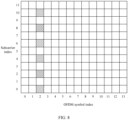
- Example 1 First four subcarriers in ascending order of subcarrier indexes (relative indexes 1, 2, 3, and 4). As shown in FIG. 3 , in this case, four DMRS ports are multiplexed on subcarriers with absolute indexes 0, 2, 4, and 6 (relative indexes 1, 2, 3, and 4) in one RB in a form of CDM.
- Example 2 First four subcarriers in descending order of subcarrier indexes (relative indexes 3, 4, 5, and 6). As shown in FIG. 4 , in this case, four DMRS ports are multiplexed on subcarriers with absolute indexes 4, 6, 8, and 10 (relative indexes 3, 4, 5, and 6) in one RB in a form of CDM.
- Example 3 First two subcarriers with largest subcarrier indexes and first two subcarriers with smallest subcarrier indexes (relative indexes 1, 2, 5, and 6). As shown in FIG. 5 , in this case, four DMRS ports are multiplexed on subcarriers with absolute indexes 0, 2, 8, and 10 (relative indexes 1, 2, 5, and 6) in one RB in a form of CDM.
- Example 4 Indexes 1, 2, 4, and 5. As shown in FIG. 6 , in this case, four DMRS ports are multiplexed on subcarriers with absolute indexes 0, 2, 6, and 8 (relative indexes 1, 2, 4, and 5) in one RB in a form of CDM.
- Example 5 Indexes 2, 3, 5, and 6. As shown in FIG. 7 , in this case, four DMRS ports are multiplexed on subcarriers with absolute indexes 2, 4, 8, and 10 (relative indexes 2, 3, 5, and 6) in one RB in a form of CDM.
- Example 6 Indexes 1, 3, 4, and 6. As shown in FIG. 8 , in this case, four DMRS ports are multiplexed on subcarriers with absolute indexes 0, 4, 6, and 10 (relative indexes 1, 3, 4, and 6) in one RB in a form of CDM.
- Selection of four specific subcarriers corresponding to the DMRS ports may be agreed by a network side and a terminal side by default, or may be configured by a network side.
- the network side configures four specific subcarriers by using RRC signaling (in a form of a bitmap, six bits are used to correspond to six subcarriers in one RB, where a bit of 1 indicates that a corresponding subcarrier is selected, and a bit of 0 indicates that a corresponding subcarrier is not selected); or the network side configures a plurality of subcarrier groups by using radio resource control (Radio Resource Control, RRC) signaling, where each subcarrier group includes four subcarriers, and indicates a subcarrier group index by using a media access control control element (Media Access Control Element, MAC CE) and/or DCI.
- RRC Radio Resource Control
- MAC CE media access control control element
- subcarriers 0, 2, 4, and 6 in an RB 1 correspond to an FD-OCC sequence with a length of 4 to implement CDM multiplexing of DMRS ports; subcarriers 8 and 10 in the RB 1 and subcarriers 0 and 2 in an RB 2 correspond to an FD-OCC sequence with a length of 4 to implement CDM multiplexing of DMRS ports; and subcarriers 4, 6, 8, and 10 in the RB 2 correspond to an FD-OCC sequence with a length of 4 to implement CDM multiplexing of DMRS ports.
- a function of an FD-OCC may be performed across RBs, and two RBs are used as a granularity of the function.
- This embodiment is used to describe specific forms of an FD-OCC sequence and a TD-OCC sequence when a type of a DMRS is a DMRS configuration type 2 and a length of the FD-OCC sequence is 4.
- FD-OCC and TD-OCC sequences are generated based on a criterion of lowest cross correlation, a criterion of mutual orthogonality, or the like.
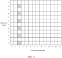
- FIG. 10 uses a single-symbol structure and a CDM group 0 as an example, and is also applicable to a CDM group 1, a CDM group 2, and/or a double-symbol structure.
- DMRS ports are multiplexed in a form of CDM on subcarriers 0, 1, 6, and 7 corresponding to a CDM group 0 in one RB, corresponding to an FD-OCC sequence with a length of 4. Therefore, when DMRS ports are also mapped on CDM groups 1 and 2, up to 12 DMRS ports are mapped in the single-symbol structure and up to 24 DMRS ports are mapped in the double-symbol structure.
- FD-OCC sequences corresponding to four DMRS ports in a CDM group are:
- Each of the first, second, third, and fourth FD-OCC sequences corresponds to one of the four DMRS ports. The following should be noted:
- values of first elements and fourth elements of the first, second, third, and fourth FD-OCC sequences are exchanged in a unified manner.
- FD-OCC sequences after the exchange are:
- FD-OCC sequences corresponding to eight DMRS ports in a CDM group are FD-OCC sequences listed above.
- TD-OCC sequences corresponding to the eight DMRS ports in one CDM group are:
- first and second TD-OCC sequence may be other forms of sequences generated based on the criterion of lowest cross correlation, the criterion of mutual orthogonality, or the like.
- port numbers of the foregoing port 0 to port 23 are 1000, 1001, 1012, 1013, 1006, 1007, 1018, 1019, 1002, 1003, 1014, 1015, 1008, 1009, 1020, 1021, 1004, 1005, 1016, 1017, 1010, 1011, 1022, and 1023 respectively.
- the FD-OCC sequences w f with lengths of 4 in the foregoing parameter tables are not limited to the four FD-OCC sequences in the parameter tables, and may also be the foregoing four DFT sequences with the lengths of 4, corresponding to four column vectors of the fourth-order DFT matrix.
- port numbers of the foregoing port 0 to port 23 may be 1000, 1001, 1012, 1013, 1006, 1007, 1018, 1019, 1002, 1003, 1014, 1015, 1008, 1009, 1020, 1021, 1004, 1005, 1016, 1017, 1010, 1011, 1022, and 1023.
- a mapping manner of DMRS ports may be the same as that of the PDSCH, that is, the formula and parameter table in the first manner or the second manner may be used. Details are not described herein again.
- the single-symbol structure of the DMRS configuration type 2 can map up to 12 orthogonal DMRS ports; and the double-symbol structure of the DMRS configuration type 2 can map up to 24 orthogonal DMRS ports.
- the following uses a single-symbol structure and a CDM group 0 as an example. This embodiment is also applicable to a CDM group 1 and/or a double-symbol structure.
- FD-OCC sequences corresponding to four DMRS ports in a CDM group are: four FD-OCC sequences with lengths of 6, which are generated based on a criterion of lowest cross correlation, a criterion of mutual orthogonality, or the like.
- four FD-OCC sequences with lengths of 6 are obtained in the following manner: Six FD-OCC sequences with lengths of 6 are generated based on a criterion of lowest cross correlation, a criterion of mutual orthogonality, or the like, and then four FD-OCC sequences with lengths of 6 are selected from the six FD-OCC sequences. Each of the four FD-OCC sequences with the lengths of 6 corresponds to one of the four DMRS ports in one CDM group.
- the FD-OCC sequences corresponding to the four DMRS ports in one CDM group are:
- Each of the first, second, third, and fourth FD-OCC sequences corresponds to one of the four DMRS ports. The following should be noted:
- first FD-OCC sequence, second FD-OCC sequence, third FD-OCC sequence, or fourth FD-OCC sequence may be one of the following sequences:
- pi represents pi ⁇
- e ⁇ (A) represents a natural constant e to the power of A, where A is a general term and may be (j * 5/3 *pi) or the like.
- values of second elements and third elements of the first, second, third, and fourth FD-OCC sequences are exchanged in a unified manner.
- the first, second, third, and fourth FD-OCC sequences are the following sequences:
- FD-OCC sequences corresponding to eight DMRS ports in a CDM group are: four FD-OCC sequences with lengths of 6, which are generated based on the criterion of lowest cross correlation, the criterion of mutual orthogonality, or the like.
- four FD-OCC sequences with lengths of 6 are obtained in the following manner: Six FD-OCC sequences with lengths of 6 are generated based on the criterion of lowest cross correlation, the criterion of mutual orthogonality, or the like, and then four FD-OCC sequences with lengths of 6 are selected from the six FD-OCC sequences.
- Each of the four FD-OCC sequences with the lengths of 6 corresponds to two of the eight DMRS ports in one CDM group.
- the FD-OCC sequences corresponding to the eight DMRS ports in one CDM group are the FD-OCC sequences listed above.
- TD-OCC sequences corresponding to the eight DMRS ports in one CDM group are:
- first and second TD-OCC sequence may be other forms of sequences generated based on the criterion of lowest cross correlation, the criterion of mutual orthogonality, or the like.
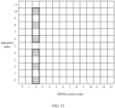
- FIG. 12 uses a single-symbol structure and a CDM group 0 as an example. This embodiment is also applicable to a CDM group 1 and/or a double-symbol structure.
- FD-OCC sequences corresponding to three DMRS ports in a CDM group are: three FD-OCC sequences with lengths of 3, which are generated based on a criterion of lowest cross correlation, a criterion of mutual orthogonality, or the like.
- Each of the three FD-OCC sequences with the lengths of 3 corresponds to one of the three DMRS ports in one CDM group.
- the FD-OCC sequences corresponding to the three DMRS ports in one CDM group are:
- Each of the first, second, and third FD-OCC sequences corresponds to one of the three DMRS ports. It should be noted that the first, second, and third FD-OCC sequences may be other forms of sequences generated based on the criterion of lowest cross correlation, the criterion of mutual orthogonality, or the like.
- FD-OCC sequences corresponding to six DMRS ports in a CDM group are: three FD-OCC sequences with lengths of 3, which are generated based on the criterion of lowest cross correlation, the criterion of mutual orthogonality, or the like.
- Each of the three FD-OCC sequences with the lengths of 3 corresponds to two of the six DMRS ports in one CDM group.
- the FD-OCC sequences corresponding to the six DMRS ports in one CDM group are:
- first, second, and third FD-OCC sequences may be other forms of sequences generated based on the criterion of lowest cross correlation, the criterion of mutual orthogonality, or the like.
- TD-OCC sequences corresponding to the six DMRS ports in one CDM group are:
- first and second TD-OCC sequence may be other forms of sequences generated based on the criterion of lowest cross correlation, the criterion of mutual orthogonality, or the like.
- the DMRS generation method provided in the embodiments of this application may be performed by a DMRS generation apparatus.
- a DMRS generation apparatus provided in the embodiments of this application is described by assuming that the DMRS generation apparatus performs the DMRS generation method in the embodiments of this application.
- FIG. 13 is a schematic diagram of a structure of a DMRS generation apparatus according to an embodiment of this application.
- the apparatus may correspond to a terminal or a network-side device in another embodiment.
- the apparatus 1300 includes the following module: a processing module 1302, configured to map an FD-OCC sequence with a length of L to L subcarriers, where the L subcarriers are specific subcarriers corresponding to N DMRS ports, the FD-OCC sequence is used for CDM of the N DMRS ports, the N DMRS ports belong to one CDM group, L and N are positive integers, and L is greater than 2.
- the apparatus 1300 further includes a communication module.
- the DMRS generation apparatus maps the FD-OCC sequence with the length of L to the L subcarriers, where the L subcarriers are the specific subcarriers corresponding to the N DMRS ports, the FD-OCC sequence is used for CDM of the N DMRS ports, and the N DMRS ports belong to one CDM group. Because L is greater than 2, this embodiment of this application is equivalent to further extending a quantity of DMRS ports by extending the length of the FD-OCC sequence. This helps increase a quantity of users in MU-MIMO to support more data streams. Therefore, a feasible solution is provided for more users multiplexed in MU-MIMO, and performance of the communication system is improved.
- the length L of the FD-OCC sequence is related to a type of DMRS, where in a case that the type of DMRS is DMRS configuration type 1, a value of L is 3, 4, or 6; or in a case that the type of DMRS is DMRS configuration type 2, a value of L is 4.
- the L subcarriers meet at least one of the following: (1) being L subcarriers with continuous relative indexes, where the relative indexes correspond to one CDM group; (2) being L subcarriers determined according to a preset rule; (3) being L subcarriers configured or indicated by a network-side device in a form of a bitmap; and (4) being L subcarriers other than unused subcarriers configured or indicated by the network-side device.
- the network-side device configures or indicates a first subcarrier among the L subcarriers.
- the L subcarriers are: four of K subcarriers corresponding to one CDM group in an RB, where K is a positive integer and K is greater than L; or four of K ⁇ M subcarriers corresponding to one CDM group in M RBs, where M is a positive integer and M is greater than 1.
- the L subcarriers are four of the K subcarriers corresponding to one CDM group in the RB, and the L subcarriers are one of the following: (1) first four subcarriers in an ascending order of relative indexes; (2) first four subcarriers in a descending order of relative indexes; (3) first two subcarriers with largest relative indexes and first two subcarriers with smallest relative indexes; (4) first two subcarriers in an ascending order of relative indexes among first K/2 subcarriers in an ascending order of relative indexes and first two subcarriers in an ascending order of relative indexes among last K/2 subcarriers in an ascending order of relative indexes; (5) last two subcarriers in an ascending order of relative indexes among the first K/2 subcarriers in the ascending order of relative indexes and last two subcarriers in an ascending order of relative indexes among the last K/2 subcarriers in the ascending order of relative indexes;
- the L subcarriers are L of the K ⁇ M subcarriers corresponding to one CDM group in the M RBs, where the K ⁇ M subcarriers are divided into (K ⁇ M ⁇ L) parts, and there are L subcarriers in each part.
- relative indexes of the L subcarriers are adjacent; or an interval between relative indexes of the L subcarriers is P, where P is a positive integer, and the relative indexes correspond to one CDM group.
- a value of M meets at least one of the following that: (1) the value is agreed by a network-side device and a terminal side by default; (2) the value is configured or indicated by the network-side device; (3) the value is consistent with a granularity of a precoding resource block group PRG; and (4) the value is an integer multiple of 2.
- the L subcarriers are L of the K ⁇ M subcarriers corresponding to one CDM group in the M RBs, where a bandwidth of a data channel scheduled by a network-side device for a terminal meets at least one of the following that: (1) a quantity of RBs in the bandwidth is an integer multiple of M; (2) a difference between a start RB position of the bandwidth and a CRB 0 is an integer multiple of M or 0; (3) a difference between the start RB position of the bandwidth and a start RB position of a BWP in which the bandwidth is located is an integer multiple of M or 0; (4) a difference between start RB positions of data channels scheduled by a plurality of terminals corresponding to the N DMRS ports is an integer multiple of M or 0; (5) a quantity of RBs corresponding to each continuous RB segment in the bandwidth is an integer multiple of M; and (6) a difference between a start RB position of each continuous RB segment in the bandwidth and the CRB 0
- the L subcarriers are L of the K subcarriers corresponding to one CDM group in the RB; and a ratio of EPRE of a data channel to EPRE of the DMRS meets at least one of the following that: (1) when one CDM group is not occupied by data, the ratio of the EPRE of the data channel to the EPRE of the DMRS is 0 dB; and (2) when two CDM groups are not occupied by data, the ratio of the EPRE of the data channel to the EPRE of the DMRS is -4.77 dB.
- the L subcarriers are L subcarriers corresponding to one CDM group in the RB; or in a case that the type of DMRS is DMRS configuration type 2 and that the value of L is 4, the L subcarriers are L subcarriers corresponding to one CDM group in the RB.
- the FD-OCC sequence with the length of L is used in combination with a time division-orthogonal cover code TD-OCC sequence with a length of J, where J is a positive integer.
- the FD-OCC sequence with the length of L acts on the N DMRS ports as a first capability of a terminal, where a terminal that does not support the first capability and a terminal that supports the first capability support multi-user multiple-input multiple-output MU-MIMO multiplexing.
- the terminal that does not support the first capability and the terminal that supports the first capability meet at least one of the following that: (1) MU-MIMO multiplexing is performed in a form of frequency division multiplexing FDM on DMRS ports corresponding to the terminal that does not support the first capability and the terminal that supports the first capability; (2) MU-MIMO multiplexing is performed in a form of time division multiplexing TDM on the DMRS ports corresponding to the terminal that does not support the first capability and the terminal that supports the first capability; and (3) MU-MIMO multiplexing is performed in a form of CDM on the DMRS ports corresponding to the terminal that does not support the first capability and the terminal that supports the first capability.
- the FD-OCC sequence meets one of the following: (1) lowest cross correlation between sequences; and (2) mutual orthogonality between sequences.
- the FD-OCC sequence is at least one of the following: (1) a CGS; (2) a DFT sequence; (3) a sequence whose elements are BPSK symbols; (4) a sequence whose elements are QPSK symbols; (5) a sequence whose elements are 6PSK symbols; (6) a sequence whose elements are 8PSK symbols; (7) a sequence whose elements include 1 and -1; and (8) a sequence whose elements include 1, -1, an imaginary number j, and an imaginary number -j.
- the DMRS generation apparatus in this embodiment of this application may be an electronic device, for example, an electronic device with an operating system, or may be a component in an electronic device, for example, an integrated circuit or a chip.
- the electronic device may be a terminal, or may be other devices than a terminal.
- the terminal may include but is not limited to the foregoing illustrated type of the terminal 11.
- the other devices may be a server, a network attached storage (Network Attached Storage, NAS), and the like. This is not specifically limited in this embodiment of this application.
- the DMRS generation apparatus provided in this embodiment of this application can implement each process implemented in the method embodiment in FIG. 2 , with the same technical effect achieved. To avoid repetition, details are not described herein again.
- an embodiment of this application further provides a communication device 1400, including a processor 1401 and a memory 1402.
- a program or instructions are stored in the memory 1402 and executable on the processor 1401.
- the communication device 1400 is a terminal, and the program or instructions are executed by the processor 1401, each step of the foregoing embodiment of the DMRS generation method is implemented, with the same technical effect achieved.
- the communication device 1400 is a network-side device, and the program or instructions are executed by the processor 1401, each step of the foregoing embodiment of the DMRS generation method is implemented, with the same technical effect achieved. To avoid repetition, details are not described herein again.
- An embodiment of this application further provides a terminal, including a processor and a communication interface.
- the processor is configured to map an FD-OCC sequence with a length of L to L subcarriers, where the L subcarriers are specific subcarriers corresponding to N DMRS ports, the FD-OCC sequence is used for CDM of the N DMRS ports, the N DMRS ports belong to one CDM group, L and N are positive integers, and L is greater than 2.
- the terminal embodiment corresponds to the foregoing terminal-side method embodiment, and each implementation process and implementation of the foregoing method embodiment can be applied to the terminal embodiment, with the same technical effect achieved.
- FIG. 15 is a schematic diagram of a hardware structure of a terminal for implementing an embodiment of this application.
- the terminal 1500 includes but is not limited to at least some components such as a radio frequency unit 1501, a network module 1502, an audio output unit 1503, an input unit 1504, a sensor 1505, a display unit 1506, a user input unit 1507, an interface unit 1508, a memory 1509, and a processor 1510.
- the terminal 1500 may further include a power supply (for example, a battery) supplying power to all components.
- the power supply may be logically connected to the processor 1510 through a power management system. In this way, functions such as charge management, discharge management, and power consumption management are implemented by using the power management system.
- the terminal structure shown in FIG. 15 does not constitute a limitation on the terminal.
- the terminal may include more or fewer components than those shown in the figure, or some components are combined, or component arrangements are different. Details are not described herein again.
- the input unit 1504 may include a graphics processing unit (Graphics Processing Unit, GPU) 15041 and a microphone 15042.
- the graphics processing unit 15041 processes image data of a still picture or video obtained by an image capture apparatus (such as a camera) in a video capture mode or an image capture mode.
- the display unit 1506 may include a display panel 15061, and the display panel 15061 may be configured in a form of a liquid crystal display, an organic light-emitting diode, or the like.
- the user input unit 1507 includes at least one of a touch panel 15071 and other input devices 15072.
- the touch panel 15071 is also referred to as a touchscreen.
- the touch panel 15071 may include two parts: a touch detection apparatus and a touch controller.
- the other input devices 15072 may include but are not limited to a physical keyboard, a function button (such as a volume control button or a power button), a trackball, a mouse, and a joystick. Details are not described herein again.
- the radio frequency unit 1501 may transmit the downlink data to the processor 1510 for processing.
- the radio frequency unit 1501 may send uplink data to the network-side device.
- the radio frequency unit 1501 includes but is not limited to an antenna, an amplifier, a transceiver, a coupler, a low noise amplifier, a duplexer, and the like.
- the memory 1509 may be configured to store software programs or instructions and various data.
- the memory 1509 may primarily include a first storage area for storing programs or instructions and a second storage area for storing data.
- the first storage area may store an operating system, an application program or instructions required by at least one function (such as an audio play function and an image play function), and the like.
- the memory 1509 may include a volatile memory or a non-volatile memory, or the memory 1509 may include both a volatile memory and a non-volatile memory.
- the non-volatile memory may be a read-only memory (Read-Only Memory, ROM), a programmable read-only memory (Programmable ROM, PROM), an erasable programmable read-only memory (Erasable PROM, EPROM), an electrically erasable programmable read-only memory (Electrically EPROM, EEPROM), or a flash memory.
- ROM Read-Only Memory
- PROM programmable read-only memory
- Erasable PROM Erasable PROM
- EPROM electrically erasable programmable read-only memory
- EEPROM electrically erasable programmable read-only memory
- the volatile memory may be a random access memory (Random Access Memory, RAM), a static random access memory (Static RAM, SRAM), a dynamic random access memory (Dynamic RAM, DRAM), a synchronous dynamic random access memory (Synchronous DRAM, SDRAM), a double data rate synchronous dynamic random access memory (Double Data rate SDRAM, DDR SDRAM), an enhanced synchronous dynamic random access memory (Enhanced SDRAM, ESDRAM), a synchlink dynamic random access memory (Synch Link DRAM, SLDRAM), and a direct rambus random access memory (Direct Rambus RAM, DRRAM).
- RAM Random Access Memory
- SRAM static random access memory
- DRAM dynamic random access memory
- DRAM synchronous dynamic random access memory
- SDRAM double data rate synchronous dynamic random access memory
- Enhanced SDRAM, ESDRAM enhanced synchronous dynamic random access memory
- Synch Link DRAM Synchlink dynamic random access memory
- SLDRAM direct rambus random access memory
- Direct Rambus RAM Direct Rambus RAM,
- the processor 1510 may include one or more processing units.
- the processor 1510 integrates an application processor and a modem processor.
- the application processor mainly processes operations related to the operating system, a user interface, an application program, and the like.
- the modem processor mainly processes a wireless communication signal.
- the modem processor is a baseband processor. It may be understood that the modem processor may alternatively not be integrated in the processor 1510.
- the processor 1510 may be configured to map an FD-OCC sequence with a length of L to L subcarriers, where the L subcarriers are specific subcarriers corresponding to N DMRS ports, the FD-OCC sequence is used for CDM of the N DMRS ports, the N DMRS ports belong to one CDM group, L and N are positive integers, and L is greater than 2.
- the terminal provided in this embodiment of this application maps the FD-OCC sequence with the length of L to the L subcarriers, where the L subcarriers are the specific subcarriers corresponding to the N DMRS ports, the FD-OCC sequence is used for CDM of the N DMRS ports, and the N DMRS ports belong to one CDM group. Because L is greater than 2, this embodiment of this application is equivalent to further extending a quantity of DMRS ports by extending the length of the FD-OCC sequence. This helps increase a quantity of users in MU-MIMO to support more data streams. Therefore, a feasible solution is provided for more users multiplexed in MU-MIMO, and performance of the communication system is improved.
- the terminal 1500 provided in this embodiment of this application can further implement each process of the foregoing embodiment of the DMRS generation method, with the same technical effect achieved. To avoid repetition, details are not described herein again.
- An embodiment of this application further provides a network-side device, including a processor and a communication interface.
- the processor is configured to map an FD-OCC sequence with a length of L to L subcarriers, where the L subcarriers are specific subcarriers corresponding to N DMRS ports, the FD-OCC sequence is used for CDM of the N DMRS ports, the N DMRS ports belong to one CDM group, L and N are positive integers, and L is greater than 2.
- the network-side device embodiment corresponds to the foregoing method embodiment of the network-side device, and each implementation process and implementation of the foregoing method embodiment can be applied to the network-side device embodiment, with the same technical effect achieved.
- the network-side device 1600 includes an antenna 161, a radio frequency apparatus 162, a baseband apparatus 163, a processor 164, and a memory 165.
- the antenna 161 is connected to the radio frequency apparatus 162.
- the radio frequency apparatus 162 receives information by using the antenna 161, and sends the received information to the baseband apparatus 163 for processing.
- the baseband apparatus 163 processes to-be-sent information, and sends the information to the radio frequency apparatus 162; and the radio frequency apparatus 162 processes the received information and then sends the information out by using the antenna 161.
- the method performed by the network-side device in the foregoing embodiment may be implemented in the baseband apparatus 163.
- the baseband apparatus 163 includes a baseband processor.
- the baseband apparatus 163 may include, for example, at least one baseband unit, where a plurality of chips are disposed on the baseband unit. As shown in FIG. 16 , one of the chips is, for example, the baseband processor, connected to the memory 165 by using a bus interface, to invoke a program in the memory 165 to perform the operation of the network device shown in the foregoing method embodiment.
- the network-side device may further include a network interface 166, where the interface is, for example, a common public radio interface (Common Public Radio Interface, CPRI).
- CPRI Common Public Radio Interface
- the network-side device 1600 in this embodiment of the present invention further includes a program or instructions stored in the memory 165 and executable on the processor 164.
- the processor 164 invokes the program or instructions in the memory 165, the method performed by each module shown in FIG. 13 is performed, with the same technical effect achieved. To avoid repetition, details are not described herein again.
- An embodiment of this application further provides a readable storage medium.
- the readable storage medium stores a program or instructions.
- the program or instructions are executed by a processor, each process of the foregoing embodiment of the DMRS generation method is implemented, with the same technical effect achieved. To avoid repetition, details are not described herein again.
- the processor is a processor in the terminal in the foregoing embodiment.
- the readable storage medium includes a computer-readable storage medium, such as a computer read-only memory ROM, a random access memory RAM, a magnetic disk, or an optical disc.
- an embodiment of this application provides a chip.
- the chip includes a processor and a communication interface.
- the communication interface is coupled to the processor.
- the processor is configured to run a program or instructions to implement each process of the foregoing embodiment of the DMRS generation method, with the same technical effect achieved. To avoid repetition, details are not described herein again.
- the chip provided in this embodiment of this application may also be referred to as a system-level chip, a system chip, a chip system, a system-on-chip, or the like.
- an embodiment of this application provides a computer program or program product.
- the computer program or program product is stored in a storage medium.
- the computer program or program product is executed by at least one processor to implement each process of the foregoing embodiment of the DMRS generation method, with the same technical effect achieved. To avoid repetition, details are not described herein again.
- An embodiment of this application further provides a DMRS generation system, including a terminal and a network-side device.
- the terminal may be configured to perform the steps of the foregoing DMRS generation method.
- the network-side device may be configured to perform the steps of the foregoing DMRS generation method.
- the computer software product is stored in a storage medium (such as a ROM/RAM, a magnetic disk, or an optical disc), and includes several instructions for instructing a terminal (which may be a mobile phone, a computer, a server, an air conditioner, a network device, or the like) to perform the methods described in the embodiments of this application.
- a storage medium such as a ROM/RAM, a magnetic disk, or an optical disc
- a terminal which may be a mobile phone, a computer, a server, an air conditioner, a network device, or the like
Landscapes
- Engineering & Computer Science (AREA)
- Signal Processing (AREA)
- Computer Networks & Wireless Communication (AREA)
- Mobile Radio Communication Systems (AREA)
Applications Claiming Priority (4)
| Application Number | Priority Date | Filing Date | Title |
|---|---|---|---|
| CN202210090244 | 2022-01-25 | ||
| CN202211103535 | 2022-09-09 | ||
| CN202211297196.6A CN116506952A (zh) | 2022-01-25 | 2022-10-21 | Dmrs生成方法、终端及网络侧设备 |
| PCT/CN2023/073086 WO2023143353A1 (zh) | 2022-01-25 | 2023-01-19 | Dmrs生成方法、终端及网络侧设备 |
Publications (2)
| Publication Number | Publication Date |
|---|---|
| EP4472318A1 true EP4472318A1 (de) | 2024-12-04 |
| EP4472318A4 EP4472318A4 (de) | 2025-04-23 |
Family
ID=87317181
Family Applications (1)
| Application Number | Title | Priority Date | Filing Date |
|---|---|---|---|
| EP23746234.6A Pending EP4472318A4 (de) | 2022-01-25 | 2023-01-19 | Dmrs-erzeugungsverfahren sowie endgerät und netzwerkseitige vorrichtung |
Country Status (4)
| Country | Link |
|---|---|
| US (1) | US20240380551A1 (de) |
| EP (1) | EP4472318A4 (de) |
| CN (1) | CN116506952A (de) |
| WO (1) | WO2023143353A1 (de) |
Families Citing this family (1)
| Publication number | Priority date | Publication date | Assignee | Title |
|---|---|---|---|---|
| CN120454950A (zh) * | 2024-02-07 | 2025-08-08 | 华为技术有限公司 | 通信方法和通信装置 |
Family Cites Families (5)
| Publication number | Priority date | Publication date | Assignee | Title |
|---|---|---|---|---|
| WO2016127309A1 (en) * | 2015-02-10 | 2016-08-18 | Qualcomm Incorporated | Dmrs enhancement for higher order mu-mimo |
| KR102455798B1 (ko) * | 2017-08-24 | 2022-10-19 | 삼성전자 주식회사 | 무선 셀룰라 통신 시스템에서 dmrs 포트 그룹핑 방법 및 장치 |
| EP3468061A1 (de) * | 2017-10-03 | 2019-04-10 | Panasonic Intellectual Property Corporation of America | Signalisierungsaspekte zur anzeige von co-geplanten dmrs-ports in mu-mimo |
| WO2021024330A1 (ja) * | 2019-08-02 | 2021-02-11 | 株式会社Nttドコモ | 端末及び無線通信方法 |
| US11902069B2 (en) * | 2019-08-02 | 2024-02-13 | Ntt Docomo, Inc. | Terminal and radio communication method |
-
2022
- 2022-10-21 CN CN202211297196.6A patent/CN116506952A/zh active Pending
-
2023
- 2023-01-19 WO PCT/CN2023/073086 patent/WO2023143353A1/zh not_active Ceased
- 2023-01-19 EP EP23746234.6A patent/EP4472318A4/de active Pending
-
2024
- 2024-07-24 US US18/782,292 patent/US20240380551A1/en active Pending
Also Published As
| Publication number | Publication date |
|---|---|
| EP4472318A4 (de) | 2025-04-23 |
| WO2023143353A1 (zh) | 2023-08-03 |
| US20240380551A1 (en) | 2024-11-14 |
| CN116506952A (zh) | 2023-07-28 |
Similar Documents
| Publication | Publication Date | Title |
|---|---|---|
| US9843466B2 (en) | Method and apparatus for generating an uplink reference signal sequence in a wireless communication system | |
| US9025684B2 (en) | Method for generating and transmitting a reference signal for uplink demodulation in a clustered DFT-spread OFDM transmission scheme | |
| US10069610B2 (en) | Method and apparatus for generating a reference signal sequence in a wireless communication system | |
| CN107040354B (zh) | 上行dmrs的配置方法、网元、上行dmrs的传输方法和装置 | |
| CA2786700C (en) | Method and apparatus for generating a reference signal sequence in a wireless communication system | |
| EP2534803B1 (de) | System und verfahren für verbesserte steuerkanal-übertragungsdiversität | |
| EP3890233A1 (de) | Signalverarbeitungsverfahren und -vorrichtung | |
| EP2494727A1 (de) | Downlink-steuerungssignalisierung für downlink-mimo | |
| EP3403454B1 (de) | Steuerkanalentwurf und verwendung für schmalbandige kommunikation | |
| CN110912666A (zh) | 参考信号及序列配置方法和装置 | |
| JP2021523637A (ja) | 通信方法および通信装置 | |
| EP4436262A1 (de) | Hybrides mehrfachzugangskommunikationsverfahren und vorrichtung sowie endgerät und netzwerkseitige vorrichtung | |
| US20240292430A1 (en) | Information transmission method and apparatus, terminal, network side device, and readable storage medium | |
| US20250294467A1 (en) | Uplink transmission transmit power determining method and apparatus, terminal, and network side device | |
| EP4460128A1 (de) | Pdcch-überwachungsverfahren und -vorrichtung, endgerät und speichermedium | |
| US20250227697A1 (en) | Dci parsing method, dynamic waveform switching determining method, uplink receiving determining method, apparatus, terminal, and network-side device | |
| CN115473617B (zh) | 参考信号配置方法和装置 | |
| US20240380551A1 (en) | DMRS Generation Method, and Terminal and Network-Side Device | |
| US20250343655A1 (en) | Phase tracking reference signal transmission method and apparatus, terminal, and network-side device | |
| CN118118140A (zh) | 上行参考信号资源传输方法、装置、终端及网络侧设备 | |
| US20250023686A1 (en) | Demodulation Reference Signal Transmission Method and Apparatus, Terminal, and Network-Side Device | |
| US20240243773A1 (en) | Spectrum spreading method and apparatus, communication device, and readable storage medium | |
| CN116846523A (zh) | Dmrs传输方法、装置及相关设备 | |
| WO2011120584A1 (en) | Sequence hopping in a communication system | |
| EP4507228A1 (de) | Dmrs-portinformationsanzeigeverfahren, endgerät und netzwerkseitige vorrichtung |
Legal Events
| Date | Code | Title | Description |
|---|---|---|---|
| STAA | Information on the status of an ep patent application or granted ep patent |
Free format text: STATUS: THE INTERNATIONAL PUBLICATION HAS BEEN MADE |
|
| PUAI | Public reference made under article 153(3) epc to a published international application that has entered the european phase |
Free format text: ORIGINAL CODE: 0009012 |
|
| STAA | Information on the status of an ep patent application or granted ep patent |
Free format text: STATUS: REQUEST FOR EXAMINATION WAS MADE |
|
| 17P | Request for examination filed |
Effective date: 20240820 |
|
| AK | Designated contracting states |
Kind code of ref document: A1 Designated state(s): AL AT BE BG CH CY CZ DE DK EE ES FI FR GB GR HR HU IE IS IT LI LT LU LV MC ME MK MT NL NO PL PT RO RS SE SI SK SM TR |
|
| REG | Reference to a national code |
Ref country code: DE Ref legal event code: R079 Free format text: PREVIOUS MAIN CLASS: H04W0072040000 Ipc: H04B0007045200 |
|
| A4 | Supplementary search report drawn up and despatched |
Effective date: 20250324 |
|
| RIC1 | Information provided on ipc code assigned before grant |
Ipc: H04J 11/00 20060101ALI20250318BHEP Ipc: H04L 5/00 20060101ALI20250318BHEP Ipc: H04B 7/0452 20170101AFI20250318BHEP |
|
| DAV | Request for validation of the european patent (deleted) | ||
| DAX | Request for extension of the european patent (deleted) |