EP4472151A1 - Wireless communication method, wireless communication system, and transmission device - Google Patents
Wireless communication method, wireless communication system, and transmission device Download PDFInfo
- Publication number
- EP4472151A1 EP4472151A1 EP22923751.6A EP22923751A EP4472151A1 EP 4472151 A1 EP4472151 A1 EP 4472151A1 EP 22923751 A EP22923751 A EP 22923751A EP 4472151 A1 EP4472151 A1 EP 4472151A1
- Authority
- EP
- European Patent Office
- Prior art keywords
- phase shift
- transmission data
- processing
- shift amount
- transmission
- Prior art date
- Legal status (The legal status is an assumption and is not a legal conclusion. Google has not performed a legal analysis and makes no representation as to the accuracy of the status listed.)
- Pending
Links
Images




Classifications
-
- H—ELECTRICITY
- H04—ELECTRIC COMMUNICATION TECHNIQUE
- H04L—TRANSMISSION OF DIGITAL INFORMATION, e.g. TELEGRAPHIC COMMUNICATION
- H04L27/00—Modulated-carrier systems
- H04L27/26—Systems using multi-frequency codes
- H04L27/2601—Multicarrier modulation systems
- H04L27/2614—Peak power aspects
- H04L27/2621—Reduction thereof using phase offsets between subcarriers
-
- H—ELECTRICITY
- H04—ELECTRIC COMMUNICATION TECHNIQUE
- H04L—TRANSMISSION OF DIGITAL INFORMATION, e.g. TELEGRAPHIC COMMUNICATION
- H04L27/00—Modulated-carrier systems
- H04L27/26—Systems using multi-frequency codes
- H04L27/2601—Multicarrier modulation systems
- H04L27/2614—Peak power aspects
-
- H—ELECTRICITY
- H04—ELECTRIC COMMUNICATION TECHNIQUE
- H04B—TRANSMISSION
- H04B7/00—Radio transmission systems, i.e. using radiation field
- H04B7/02—Diversity systems; Multi-antenna system, i.e. transmission or reception using multiple antennas
- H04B7/04—Diversity systems; Multi-antenna system, i.e. transmission or reception using multiple antennas using two or more spaced independent antennas
- H04B7/0413—MIMO systems
- H04B7/0456—Selection of precoding matrices or codebooks, e.g. using matrices antenna weighting
Definitions
- the present invention relates to a wireless communication technology.
- the present invention relates to a wireless communication technology for performing precoding on transmission data on a transmitting side.
- a transmitting side may perform precoding on transmission data. For example, when wideband transmission is performed under a frequency-selective fading environment, channel equalization is performed by precoding. As another example, in a multiple-input multiple-output (MIMO) system, stream separation is performed by precoding.
- MIMO multiple-input multiple-output
- PAPR peak to average power ratio
- Non Patent Literature 1 discloses a technique for reducing a PAPR in a wideband single-carrier MIMO system.
- Non Patent Literature 1 Kuriyama et al., "PAPR Reduction on Wideband Single-Carrier MIMO Systems with Variable Tap-Length FIR Beamforming", Society Conference of the Institute of Electronics, Information and Communication Engineers, B-5-70, September 2021 .
- the PAPR increases.
- One object of the present invention is to provide a technique capable of reducing a PAPR when a transmitting side performs precoding on transmission data in wireless communication.
- a first aspect relates to a wireless communication method for performing wireless communication between a transmission device and a reception device.
- the wireless communication method includes:
- a plurality of types of phase shift patterns prepared in advance define different phase shift amounts.
- the phase shift amount determination processing includes:
- a second aspect relates to a wireless communication system.
- the wireless communication system includes a transmission device and a reception device.
- the transmission device is configured to execute:
- a plurality of types of phase shift patterns prepared in advance define different phase shift amounts.
- the phase shift amount determination processing includes:
- a third aspect relates to a transmission device that performs wireless communication with a reception device.
- the transmission device includes:
- a plurality of types of phase shift patterns prepared in advance define different phase shift amounts.
- the phase shift amount determination unit is configured to select, from among the plurality of types of phase shift patterns, one that minimizes a PAPR of the transmission data after the precoding processing or one with the highest reception quality of the transmission data in the reception device.
- phase shift amount determination unit is configured to determine the phase shift amount for each of the streams according to the selected phase shift pattern.
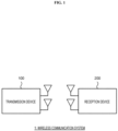
- FIG. 1 is a conceptual diagram schematically illustrating a configuration of a wireless communication system 1 according to the present embodiment.
- the wireless communication system 1 includes a transmission device 100 and a reception device 200.
- the transmission device 100 and the reception device 200 perform wireless communication.
- the wireless communication system 1 may be a multiple-input multiple-output (MIMO) system, a single-input single-output (SISO) system, or another system.
- MIMO multiple-input multiple-output
- SISO single-input single-output
- the wireless communication system 1 may perform single-carrier transmission or may perform multi-carrier transmission based on orthogonal frequency division multiplexing (OFDM) or the like.
- OFDM orthogonal frequency division multiplexing
- the transmission device 100 performs precoding on the transmission data before transmitting the transmission data to the reception device 200.
- Precoding is a well-known technique. For example, when wideband transmission is performed under a frequency-selective fading environment, channel equalization is performed by precoding. As another example, in a MIMO system, stream separation is performed by precoding.
- FIG. 2 is a block diagram illustrating a basic configuration example of the transmission device 100 that performs precoding.
- the transmission device 100 includes a modulation unit 110, a precoding unit 120, a D/A conversion unit 130, and an amplification unit 140.
- the modulation unit 110 receives transmission data (transmission signal) TD0 transmitted from the transmission device 100 to the reception device 200.
- the modulation unit 110 performs "modulation processing" for modulating the transmission data TD0 using a predetermined modulation scheme. Examples of the predetermined modulation scheme include quadrature amplitude modulation (QAM), quadrature phase shift keying (QPSK), and the like.
- the modulation unit 110 outputs transmission data TD1 after the modulation processing.
- the precoding unit 120 receives the transmission data TD1 after the modulation processing.
- the precoding unit 120 performs "precoding processing" for performing precoding on the transmission data TD1.
- Various examples are known as precoding weights (precoding matrices) used in precoding processing. In the present embodiment, the precoding weights are not particularly limited.
- the precoding unit 120 outputs transmission data TD2 after the precoding processing.
- the D/A conversion unit 130 receives the transmission data TD2 after the precoding processing.
- the D/A conversion unit 130 performs D/A conversion on the transmission data TD2 and outputs transmission data TD3.
- the amplification unit 140 receives the transmission data TD3 after the D/A conversion.
- the amplification unit 140 includes a power amplifier, and performs "amplification processing" for amplifying the transmission data TD3.
- the amplification unit 140 performs "transmission processing” for transmitting transmission data (a transmission signal) TD4 after the amplification processing to the reception device 200 via an antenna.
- the amplification unit 140 also functions as a "transmission unit” that performs transmission processing.
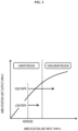
- FIG. 3 is a conceptual diagram for describing amplification characteristics of the amplification unit 140.
- the horizontal axis represents input signal power, and the vertical axis represents output signal power.
- the amplification characteristics include not only a linear region but also a nonlinear region, and the influence of the nonlinear characteristics increases as the input signal power increases. Even if the average power is included in the linear region, an input signal with a high peak to average power ratio (PAPR) is affected by the nonlinear characteristics. As a result, distortion of a constellation of transmission data may occur.
- PAPR peak to average power ratio
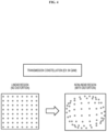
- FIG. 4 is a conceptual diagram for describing distortion of a constellation of transmission data.
- a constellation of transmission data in the case of 64 QAM is illustrated.
- distortion occurs in the constellation in the nonlinear region.
- the transmission device 100 performs precoding on transmission data. Precoding with signal superposition tends to increase a PAPR. Therefore, transmission data (a transmission signal) with a high PAPR is input to the amplification unit 140, and there is a concern of nonlinear distortion occurring due to the influence of nonlinear characteristics. When the nonlinear distortion of the transmission data occurs, there is a concern that communication with many errors will be performed.
- the present embodiment provides a technique capable of reducing a PAPR when the transmission device 100 performs precoding on transmission data.
- the present embodiment introduces a "phase shift" described below to reduce a PAPR.
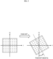
- FIG. 5 is a conceptual diagram for describing a basis of a phase shift according to the present embodiment.
- the modulation scheme is 64 QAM is illustrated.
- the modulation scheme is not limited to 64 QAM.
- the transmission device 100 (modulation unit 110) performs modulation processing for modulating transmission data using a predetermined modulation scheme.
- the transmission device 100 not only modulates the transmission data using a predetermined modulation scheme, but also applies a phase shift to the transmission data.
- the phase shift amount is ⁇ s. That is, in the modulation processing, the transmission device 100 modulates the transmission data using a predetermined modulation scheme, and further shifts the phase of the transmission data according to the phase shift amount ⁇ s.
- FIG. 6 is a conceptual diagram for describing an outline of the phase shift according to the present embodiment.
- the transmission device 100 transmits transmission data using a plurality of streams.
- the transmission device 100 determines the phase shift amount ⁇ s for each stream of transmission data and performs phase shift. That is, the phase shift amount ⁇ s is separately determined in the stream direction, and the phase shift is performed according to the phase shift amount ⁇ s for each stream.
- phase shift pattern PAT that defines the phase shift amount ⁇ s for each stream is prepared in advance.
- the phase shift pattern PAT defines the phase shift amount ⁇ s for each stream such that the phase shift amount ⁇ s differs between two or more streams.
- FIG. 7 is a conceptual diagram for describing an example of the phase shift pattern PAT according to the present embodiment.
- Phase shift processing is performed in a predetermined data unit (ex: frame, slot).
- the phase shift amount ⁇ s is determined separately for each stream.
- ⁇ s i ⁇ 1 ⁇ / N
- the parameter N is an integer other than 0.
- the phase shift amount ⁇ s differs by a certain amount ( ⁇ /N) sequentially between streams.
- the first stream S1 is a reference stream, and no phase shift is performed on the first stream S1.
- a plurality of types of phase shift patterns PAT are prepared in advance.
- the plurality of types of phase shift patterns PAT define different phase shift amounts ⁇ s.
- the transmission device 100 selects one from among a plurality of types of phase shift patterns PAT. For example, the transmission device 100 performs modulation processing using each of a plurality of types of phase shift patterns PAT, and further performs subsequent processing. Then, the transmission device 100 calculates a PAPR of the transmission data after the precoding processing by the precoding unit 120, and selects one that minimizes a PAPR from among the plurality of types of phase shift patterns PAT. As another example, the transmission device 100 may acquire information on reception quality (ex: a bit error rate (BER)) from the reception device 200 and select one that maximizes a reception quality from among the plurality of types of phase shift patterns PAT.
- BER bit error rate
- the transmission device 100 determines the phase shift amount ⁇ s for each stream of the transmission data according to the selected one phase shift pattern PAT. Thereafter, the transmission device 100 performs modulation processing according to the determined phase shift amount ⁇ s, and further performs subsequent processing.
- FIG. 8 is a conceptual diagram for describing "signal addition processing" according to the present embodiment.
- the transmission device 100 adds an index signal (control signal) indicating the selected one phase shift pattern PAT to each stream of transmission data. More specifically, the transmission device 100 adds an index signal to the head or end of a predetermined data unit (ex: frame, slot). No index signal may be added to the reference stream (the first stream S1 in the example illustrated in FIGS. 7 and 8 ) in which no phase shift is performed.
- the reception device 200 receives the transmission data transmitted from the transmission device 100 as reception data.
- the reception device 200 can recognize the phase shift pattern PAT applied to a predetermined data unit on the basis of the index signal added to the reception data. Then, the reception device 200 demodulates the reception data in consideration of the phase shift pattern PAT applied to the data unit. That is, when demodulating the reception data, the reception device 200 returns the phase by the phase shift amount ⁇ s for each stream included in the reception data.
- FIG. 9 is a conceptual diagram for describing an effect of the phase shift according to the present embodiment.
- the distribution (symbol distribution) of the symbol sequence in the constellation becomes closer to a circular shape due to the phase shift. Since the symbol phase causing the peak power is shifted, the peak power decreases at the time of signal superposition by precoding. Furthermore, since the zero point is not passed when transitioning to a symbol at a point-symmetrical position, the average power increases as compared with the case where no phase shift is performed. In this way, the PAPR can be reduced by performing the phase shift during the modulation processing of the transmission data.
- FIG. 10 is a flowchart schematically illustrating processing by the transmission device 100 according to the present embodiment.
- Step S 110 the transmission device 100 performs "phase shift amount determination processing". That is, the transmission device 100 determines the phase shift amount ⁇ s for each stream of the transmission data. More specifically, the transmission device 100 selects one from among a plurality of types of phase shift patterns PAT prepared in advance. For example, the transmission device 100 selects one that minimizes a PAPR of the transmission data after the precoding processing from among a plurality of types of phase shift patterns PAT. As another example, the transmission device 100 may select one that maximizes a reception quality of the transmission data in the reception device 200 from among a plurality of types of phase shift patterns PAT. Then, the transmission device 100 determines the phase shift amount ⁇ s for each stream according to the selected phase shift pattern PAT.
- Step S120 the transmission device 100 performs "modulation processing" on the transmission data. More specifically, the transmission device 100 modulates the transmission data using a predetermined modulation scheme, and further shifts the phase according to the phase shift amount ⁇ s for each stream.
- Step S 130 the transmission device 100 performs "signal addition processing" on the transmission data. More specifically, the transmission device 100 adds an index signal (control signal) indicating the selected one phase shift pattern PAT to the stream.
- Step S140 the transmission device 100 performs "precoding processing" on the transmission data. More specifically, the transmission device 100 performs precoding on the transmission data after the modulation processing.
- Step S150 the transmission device 100 performs "transmission processing" for transmitting the transmission data after the precoding processing from the transmission device to the reception device.
- the transmission device 100 may appropriately update the phase shift pattern PAT.
- the transmission device 100 may review all types of phase shift patterns PAT again and select one from among the all types of phase shift patterns PAT.
- the transmission device 100 may review only a certain number of phase shift patterns PAT that were relatively excellent last time, and select one from among the certain number of phase shift patterns PAT.
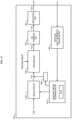
- FIG. 11 is a block diagram illustrating a first configuration example of the transmission device 100.
- the transmission device 100 includes a modulation unit 110A, a precoding unit 120, a D/A conversion unit 130, an amplification unit 140, a phase shift amount determination unit 150, a signal addition unit 160, and a PAPR calculation unit 170.
- the modulation unit 110A has a phase shift function in addition to the function of the modulation unit 110 illustrated in FIG. 2 .
- the precoding unit 120, the D/A conversion unit 130, and the amplification unit 140 are similar to those illustrated in FIG. 2 .
- the phase shift amount determination unit 150 performs "phase shift amount determination processing". That is, the phase shift amount determination unit 150 determines the phase shift amount ⁇ s for each stream of the transmission data TD0.
- the phase shift amount determination unit 150 holds information on a plurality of types of phase shift patterns PAT prepared in advance.
- the plurality of types of phase shift patterns PAT define different phase shift amounts ⁇ s.
- the phase shift amount determination unit 150 temporarily selects a plurality of types of phase shift patterns PAT one by one in order.
- the phase shift amount determination unit 150 notifies the modulation unit 110A of the phase shift amount ⁇ s for each stream defined by the temporarily selected phase shift pattern PAT.
- the modulation unit 110A receives information on the phase shift amount ⁇ s for each stream from the phase shift amount determination unit 150. In the modulation processing, the modulation unit 110A modulates the transmission data TD0 using a predetermined modulation scheme, and further shifts the phase according to the phase shift amount ⁇ s for each stream (see FIG. 7 ). The modulation unit 110A outputs transmission data TD1 after the modulation processing.
- the precoding unit 120 receives the transmission data TD1 after the modulation processing.
- the precoding unit 120 performs precoding on the transmission data TD1 and outputs transmission data TD2.
- the PAPR calculation unit 170 receives the transmission data TD2 after the precoding processing.
- the PAPR calculation unit 170 calculates a PAPR of the transmission data TD2 in a predetermined data unit according to a predetermined calculation formula.
- the PAPR calculation unit 170 outputs information on the calculated PAPR to the phase shift amount determination unit 150.
- the phase shift amount determination unit 150 acquires information on the PAPR for each of a plurality of types of phase shift patterns PAT. Then, the phase shift amount determination unit 150 selects one that minimizes a PAPR from among the plurality of types of phase shift patterns PAT. The phase shift amount determination unit 150 determines the phase shift amount ⁇ s for each stream according to the selected one phase shift pattern PAT. Then, the phase shift amount determination unit 150 notifies the modulation unit 110A of the determined phase shift amount ⁇ s for each stream. Thereafter, the modulation unit 110A performs modulation processing using the phase shift amount ⁇ s notified from the phase shift amount determination unit 150.
- the signal addition unit 160 receives information on one phase shift pattern PAT selected by the phase shift amount determination unit 150. Further, the signal addition unit 160 generates an index signal (control signal) indicating the selected one phase shift pattern PAT. Then, the signal addition unit 160 performs "signal addition processing" for adding the index signal to the stream of the transmission data TD1 (see FIG. 8 ). More specifically, the signal addition unit 160 adds an index signal to the head or end of a predetermined data unit (ex: frame, slot). Note that no phase shift is performed on the index signal.
- FIG. 12 is a block diagram illustrating a second configuration example of the transmission device 100. The descriptions overlapping with those of the first configuration example illustrated in FIG. 11 will be appropriately omitted.
- the transmission device 100 includes a reception quality information acquisition unit 180 instead of the PAPR calculation unit 170.
- the reception quality information acquisition unit 180 acquires information on the reception quality (ex: BER) of the transmission data from the reception device 200.
- the reception quality information acquisition unit 180 outputs the information on the reception quality to the phase shift amount determination unit 150.
- the phase shift amount determination unit 150 acquires information on the reception quality for each of a plurality of types of phase shift patterns PAT. Then, the phase shift amount determination unit 150 selects one that maximizes a reception quality from among the plurality of types of phase shift patterns PAT. The phase shift amount determination unit 150 determines the phase shift amount ⁇ s for each stream according to the selected one phase shift pattern PAT. Then, the phase shift amount determination unit 150 notifies the modulation unit 110A of the determined phase shift amount ⁇ s for each stream. Thereafter, the modulation unit 110A performs modulation processing using the phase shift amount ⁇ s notified from the phase shift amount determination unit 150.
- the transmission device 100 includes one or more processors (hereinafter simply referred to as a "processor”) and one or more storage devices (hereinafter simply referred to as a “storage device”).
- the processor includes a central processing unit (CPU).
- the storage device stores a variety of information necessary for processing by the processor. Examples of the storage device include a volatile memory, a non-volatile memory, a hard disk drive (HDD), a solid state drive (SSD), and the like.
- the processor may execute a control program, which is a computer program.
- the control program is stored in the storage device.
- the control program may be recorded in a computer-readable recording medium.
- the function of the processor is implemented by the processor executing the control program.
- Information on a plurality of types of phase shift patterns PAT prepared in advance is stored in the storage device.
- Functions of the modulation unit 110A, the precoding unit 120, the phase shift amount determination unit 150, the signal addition unit 160, the PAPR calculation unit 170, the reception quality information acquisition unit 180, and the like are implemented through cooperation between the processor and the storage device.
- FIG. 13 is a block diagram illustrating a configuration example of the reception device 200.
- the reception device 200 includes an amplification unit 210, an A/D conversion unit 220, and a demodulation unit 230.
- the reception device 200 receives the transmission data transmitted from the transmission device 100 as reception data (reception signal) RD0.
- the amplification unit 210 amplifies the reception data RD0 and outputs reception data RD 1.
- the A/D conversion unit 220 performs A/D conversion on the reception data RD1 and outputs reception data RD2.
- the demodulation unit 230 performs "demodulation processing" for demodulating the reception data RD2. At this time, the demodulation unit 230 demodulates the reception data RD2 in consideration of the phase shift amount ⁇ s.
- the demodulation unit 230 includes a phase shift pattern acquisition unit 240.
- the phase shift pattern acquisition unit 240 holds information on a plurality of types of phase shift patterns PAT prepared in advance.
- an index signal indicating one phase shift pattern PAT applied to transmission data of a predetermined data unit (ex: frame, slot) is added to the reception data RD2.
- the phase shift pattern acquisition unit 240 recognizes the phase shift pattern PAT applied to the transmission data in a predetermined data unit on the basis of the index signal. Then, the phase shift pattern acquisition unit 240 acquires the phase shift amount ⁇ s for each stream defined by the recognized phase shift pattern PAT.
- the demodulation unit 230 demodulates the reception data RD2 using a predetermined demodulation scheme, and returns the phase by the phase shift amount ⁇ s for each stream.
- the reception device 200 includes one or more processors (hereinafter simply referred to as "processors”) and one or more storage devices (hereinafter simply referred to as “storage devices”).
- the processor may execute a control program, which is a computer program.
- the control program is stored in the storage device.
- the control program may be recorded in a computer-readable recording medium.
- the function of the processor is implemented by the processor executing the control program.
- Information on a plurality of types of phase shift patterns PAT prepared in advance is stored in the storage device. Functions of the demodulation unit 230, the phase shift pattern acquisition unit 240, and the like are implemented through cooperation between the processor and the storage device.
Landscapes
- Engineering & Computer Science (AREA)
- Computer Networks & Wireless Communication (AREA)
- Signal Processing (AREA)
- Digital Transmission Methods That Use Modulated Carrier Waves (AREA)
Abstract
Description
- The present invention relates to a wireless communication technology. In particular, the present invention relates to a wireless communication technology for performing precoding on transmission data on a transmitting side.
- In wireless communication, a transmitting side may perform precoding on transmission data. For example, when wideband transmission is performed under a frequency-selective fading environment, channel equalization is performed by precoding. As another example, in a multiple-input multiple-output (MIMO) system, stream separation is performed by precoding.
- When precoding is performed on the transmitting side, a peak to average power ratio (PAPR) increases due to signal superposition. A transmission signal is amplified by a power amplifier before being transmitted from an antenna, but when a signal with a high PAPR is input to the power amplifier, the signal is affected by a nonlinear characteristic of the power amplifier, and nonlinear distortion may occur. When the nonlinear distortion of the transmission signal occurs, there is a concern that communication with many errors will be performed.
-
Non Patent Literature 1 discloses a technique for reducing a PAPR in a wideband single-carrier MIMO system. - Non Patent Literature 1: Kuriyama et al., "PAPR Reduction on Wideband Single-Carrier MIMO Systems with Variable Tap-Length FIR Beamforming", Society Conference of the Institute of Electronics, Information and Communication Engineers, B-5-70, September 2021.
- As described above, when the transmitting side performs precoding on transmission data in wireless communication, the PAPR increases.
- One object of the present invention is to provide a technique capable of reducing a PAPR when a transmitting side performs precoding on transmission data in wireless communication.
- A first aspect relates to a wireless communication method for performing wireless communication between a transmission device and a reception device.
- The wireless communication method includes:
- phase shift amount determination processing that determines a phase shift amount for each of streams of transmission data;
- modulation processing that modulates the transmission data and further shifts a phase according to the phase shift amount for each of the streams;
- precoding processing that performs precoding on the transmission data after the modulation processing; and
- transmission processing that transmits the transmission data after the precoding processing from the transmission device to the reception device.
- A plurality of types of phase shift patterns prepared in advance define different phase shift amounts.
- The phase shift amount determination processing includes:
- selecting, from among the plurality of types of phase shift patterns, one that minimizes a PAPR of the transmission data after the precoding processing or one that maximizes a reception quality of the transmission data in the reception device; and
- determining the phase shift amount for each of the streams according to the selected phase shift pattern.
- A second aspect relates to a wireless communication system.
- The wireless communication system includes a transmission device and a reception device.
- The transmission device is configured to execute:
- phase shift amount determination processing that determines a phase shift amount for each of streams of transmission data;
- modulation processing that modulates the transmission data and further shifts a phase according to the phase shift amount for each of the streams;
- precoding processing that performs precoding on the transmission data after the modulation processing; and
- transmission processing for transmitting the transmission data after the precoding processing to the reception device.
- A plurality of types of phase shift patterns prepared in advance define different phase shift amounts.
- The phase shift amount determination processing includes:
- selecting, from among the plurality of types of phase shift patterns, one that minimizes a PAPR of the transmission data after the precoding processing or one that maximizes a reception quality of the transmission data in the reception device; and
- determining the phase shift amount for each of the streams according to the selected phase shift pattern.
- A third aspect relates to a transmission device that performs wireless communication with a reception device.
- The transmission device includes:
- a phase shift amount determination unit configured to determine a phase shift amount for each of streams of transmission data;
- a modulation unit configured to modulate the transmission data and to further shift a phase according to the phase shift amount for each of the streams;
- a precoding unit configured to perform precoding on the transmission data after the modulation processing; and
- a transmission unit configured to transmit the transmission data after the precoding processing to the reception device.
- A plurality of types of phase shift patterns prepared in advance define different phase shift amounts.
- The phase shift amount determination unit is configured to select, from among the plurality of types of phase shift patterns, one that minimizes a PAPR of the transmission data after the precoding processing or one with the highest reception quality of the transmission data in the reception device.
- Further, the phase shift amount determination unit is configured to determine the phase shift amount for each of the streams according to the selected phase shift pattern.
- According to the present invention, it is possible to reduce a PAPR when a transmitting side performs precoding on transmission data in wireless communication.
-
-
FIG. 1 is a conceptual diagram schematically illustrating a configuration of a wireless communication system according to an embodiment. -
FIG. 2 is a block diagram illustrating a basic configuration example of a transmission device that performs precoding. -
FIG. 3 is a conceptual diagram for describing amplification characteristics of an amplification unit. -
FIG. 4 is a conceptual diagram for describing distortion of a constellation. -
FIG. 5 is a conceptual diagram for describing a basis of a phase shift according to the embodiment. -
FIG. 6 is a conceptual diagram for describing an outline of the phase shift according to the embodiment. -
FIG. 7 is a conceptual diagram for describing an example of a phase shift pattern according to the embodiment. -
FIG. 8 is a conceptual diagram for describing signal addition processing according to the embodiment. -
FIG. 9 is a conceptual diagram for describing an effect of the phase shift according to the embodiment. -
FIG. 10 is a flowchart schematically illustrating processing by the transmission device according to the embodiment. -
FIG. 11 is a block diagram illustrating a first configuration example of the transmission device according to the embodiment. -
FIG. 12 is a block diagram illustrating a second configuration example of the transmission device according to the embodiment. -
FIG. 13 is a block diagram illustrating a configuration example of a reception device according to the embodiment. - Embodiments of the present invention will be described with reference to the accompanying drawings.
-
FIG. 1 is a conceptual diagram schematically illustrating a configuration of awireless communication system 1 according to the present embodiment. Thewireless communication system 1 includes atransmission device 100 and areception device 200. Thetransmission device 100 and thereception device 200 perform wireless communication. Thewireless communication system 1 may be a multiple-input multiple-output (MIMO) system, a single-input single-output (SISO) system, or another system. Thewireless communication system 1 may perform single-carrier transmission or may perform multi-carrier transmission based on orthogonal frequency division multiplexing (OFDM) or the like. - The
transmission device 100 performs precoding on the transmission data before transmitting the transmission data to thereception device 200. Precoding is a well-known technique. For example, when wideband transmission is performed under a frequency-selective fading environment, channel equalization is performed by precoding. As another example, in a MIMO system, stream separation is performed by precoding. -
FIG. 2 is a block diagram illustrating a basic configuration example of thetransmission device 100 that performs precoding. Thetransmission device 100 includes amodulation unit 110, aprecoding unit 120, a D/A conversion unit 130, and anamplification unit 140. - The
modulation unit 110 receives transmission data (transmission signal) TD0 transmitted from thetransmission device 100 to thereception device 200. Themodulation unit 110 performs "modulation processing" for modulating the transmission data TD0 using a predetermined modulation scheme. Examples of the predetermined modulation scheme include quadrature amplitude modulation (QAM), quadrature phase shift keying (QPSK), and the like. Themodulation unit 110 outputs transmission data TD1 after the modulation processing. - The
precoding unit 120 receives the transmission data TD1 after the modulation processing. Theprecoding unit 120 performs "precoding processing" for performing precoding on the transmission data TD1. Various examples are known as precoding weights (precoding matrices) used in precoding processing. In the present embodiment, the precoding weights are not particularly limited. Theprecoding unit 120 outputs transmission data TD2 after the precoding processing. - The D/
A conversion unit 130 receives the transmission data TD2 after the precoding processing. The D/A conversion unit 130 performs D/A conversion on the transmission data TD2 and outputs transmission data TD3. - The
amplification unit 140 receives the transmission data TD3 after the D/A conversion. Theamplification unit 140 includes a power amplifier, and performs "amplification processing" for amplifying the transmission data TD3. - Furthermore, the
amplification unit 140 performs "transmission processing" for transmitting transmission data (a transmission signal) TD4 after the amplification processing to thereception device 200 via an antenna. Theamplification unit 140 also functions as a "transmission unit" that performs transmission processing. -
FIG. 3 is a conceptual diagram for describing amplification characteristics of theamplification unit 140. The horizontal axis represents input signal power, and the vertical axis represents output signal power. As illustrated inFIG. 3 , the amplification characteristics include not only a linear region but also a nonlinear region, and the influence of the nonlinear characteristics increases as the input signal power increases. Even if the average power is included in the linear region, an input signal with a high peak to average power ratio (PAPR) is affected by the nonlinear characteristics. As a result, distortion of a constellation of transmission data may occur. -
FIG. 4 is a conceptual diagram for describing distortion of a constellation of transmission data. Here, as an example, a constellation of transmission data in the case of 64 QAM is illustrated. There is no distortion in the constellation in the linear region. However, distortion occurs in the constellation in the nonlinear region. - As described above, in the present embodiment, the transmission device 100 (precoding unit 120) performs precoding on transmission data. Precoding with signal superposition tends to increase a PAPR. Therefore, transmission data (a transmission signal) with a high PAPR is input to the
amplification unit 140, and there is a concern of nonlinear distortion occurring due to the influence of nonlinear characteristics. When the nonlinear distortion of the transmission data occurs, there is a concern that communication with many errors will be performed. - Therefore, the present embodiment provides a technique capable of reducing a PAPR when the
transmission device 100 performs precoding on transmission data. The present embodiment introduces a "phase shift" described below to reduce a PAPR. -
FIG. 5 is a conceptual diagram for describing a basis of a phase shift according to the present embodiment. Here, as an example, a case where the modulation scheme is 64 QAM is illustrated. However, the modulation scheme is not limited to 64 QAM. - The transmission device 100 (modulation unit 110) performs modulation processing for modulating transmission data using a predetermined modulation scheme. In this modulation processing, the
transmission device 100 not only modulates the transmission data using a predetermined modulation scheme, but also applies a phase shift to the transmission data. The phase shift amount is θs. That is, in the modulation processing, thetransmission device 100 modulates the transmission data using a predetermined modulation scheme, and further shifts the phase of the transmission data according to the phase shift amount θs. -
FIG. 6 is a conceptual diagram for describing an outline of the phase shift according to the present embodiment. According to the present embodiment, thetransmission device 100 transmits transmission data using a plurality of streams. At that time, thetransmission device 100 determines the phase shift amount θs for each stream of transmission data and performs phase shift. That is, the phase shift amount θs is separately determined in the stream direction, and the phase shift is performed according to the phase shift amount θs for each stream. - Furthermore, according to the present embodiment, a "phase shift pattern PAT" that defines the phase shift amount θs for each stream is prepared in advance. The phase shift pattern PAT defines the phase shift amount θs for each stream such that the phase shift amount θs differs between two or more streams.
-
FIG. 7 is a conceptual diagram for describing an example of the phase shift pattern PAT according to the present embodiment. Phase shift processing is performed in a predetermined data unit (ex: frame, slot). The phase shift amount θs is determined separately for each stream. Specifically, the phase shift amount θs of the i-th stream Si (i = 1, 2, 3,...) is expressed by the following Equation (1).
- Here, the parameter N is an integer other than 0. Thus, in the example illustrated in
FIG. 7 , the phase shift amount θs differs by a certain amount (π/N) sequentially between streams. Note that, in the example illustrated inFIG. 7 , the first stream S1 is a reference stream, and no phase shift is performed on the first stream S1. - Furthermore, according to the present embodiment, a plurality of types of phase shift patterns PAT are prepared in advance. The plurality of types of phase shift patterns PAT define different phase shift amounts θs. For example, in the example illustrated in
FIG. 7 , the plurality of types of phase shift patterns PAT define the phase shift amounts θs on the basis of different parameters N (ex: N = 4, 6, 8,...). Different indexes are given to the plurality of types of phase shift patterns PAT. - The
transmission device 100 selects one from among a plurality of types of phase shift patterns PAT. For example, thetransmission device 100 performs modulation processing using each of a plurality of types of phase shift patterns PAT, and further performs subsequent processing. Then, thetransmission device 100 calculates a PAPR of the transmission data after the precoding processing by theprecoding unit 120, and selects one that minimizes a PAPR from among the plurality of types of phase shift patterns PAT. As another example, thetransmission device 100 may acquire information on reception quality (ex: a bit error rate (BER)) from thereception device 200 and select one that maximizes a reception quality from among the plurality of types of phase shift patterns PAT. - Then, the
transmission device 100 determines the phase shift amount θs for each stream of the transmission data according to the selected one phase shift pattern PAT. Thereafter, thetransmission device 100 performs modulation processing according to the determined phase shift amount θs, and further performs subsequent processing. -
FIG. 8 is a conceptual diagram for describing "signal addition processing" according to the present embodiment. Thetransmission device 100 adds an index signal (control signal) indicating the selected one phase shift pattern PAT to each stream of transmission data. More specifically, thetransmission device 100 adds an index signal to the head or end of a predetermined data unit (ex: frame, slot). No index signal may be added to the reference stream (the first stream S1 in the example illustrated inFIGS. 7 and8 ) in which no phase shift is performed. - The
reception device 200 receives the transmission data transmitted from thetransmission device 100 as reception data. Thereception device 200 can recognize the phase shift pattern PAT applied to a predetermined data unit on the basis of the index signal added to the reception data. Then, thereception device 200 demodulates the reception data in consideration of the phase shift pattern PAT applied to the data unit. That is, when demodulating the reception data, thereception device 200 returns the phase by the phase shift amount θs for each stream included in the reception data. -
FIG. 9 is a conceptual diagram for describing an effect of the phase shift according to the present embodiment. As illustrated inFIG. 9 , the distribution (symbol distribution) of the symbol sequence in the constellation becomes closer to a circular shape due to the phase shift. Since the symbol phase causing the peak power is shifted, the peak power decreases at the time of signal superposition by precoding. Furthermore, since the zero point is not passed when transitioning to a symbol at a point-symmetrical position, the average power increases as compared with the case where no phase shift is performed. In this way, the PAPR can be reduced by performing the phase shift during the modulation processing of the transmission data. -
FIG. 10 is a flowchart schematically illustrating processing by thetransmission device 100 according to the present embodiment. - In
Step S 110, thetransmission device 100 performs "phase shift amount determination processing". That is, thetransmission device 100 determines the phase shift amount θs for each stream of the transmission data. More specifically, thetransmission device 100 selects one from among a plurality of types of phase shift patterns PAT prepared in advance. For example, thetransmission device 100 selects one that minimizes a PAPR of the transmission data after the precoding processing from among a plurality of types of phase shift patterns PAT. As another example, thetransmission device 100 may select one that maximizes a reception quality of the transmission data in thereception device 200 from among a plurality of types of phase shift patterns PAT. Then, thetransmission device 100 determines the phase shift amount θs for each stream according to the selected phase shift pattern PAT. - In Step S120, the
transmission device 100 performs "modulation processing" on the transmission data. More specifically, thetransmission device 100 modulates the transmission data using a predetermined modulation scheme, and further shifts the phase according to the phase shift amount θs for each stream. - In
Step S 130, thetransmission device 100 performs "signal addition processing" on the transmission data. More specifically, thetransmission device 100 adds an index signal (control signal) indicating the selected one phase shift pattern PAT to the stream. - In Step S140, the
transmission device 100 performs "precoding processing" on the transmission data. More specifically, thetransmission device 100 performs precoding on the transmission data after the modulation processing. - In Step S150, the
transmission device 100 performs "transmission processing" for transmitting the transmission data after the precoding processing from the transmission device to the reception device. - Note that, during communication, the
transmission device 100 may appropriately update the phase shift pattern PAT. At the time of update, thetransmission device 100 may review all types of phase shift patterns PAT again and select one from among the all types of phase shift patterns PAT. Alternatively, thetransmission device 100 may review only a certain number of phase shift patterns PAT that were relatively excellent last time, and select one from among the certain number of phase shift patterns PAT. - As described above, according to the present embodiment, it is possible to reduce the PAPR when precoding is performed by applying the phase shift to the transmission data.
- Configuration examples of the
transmission device 100 and thereception device 200 will be described below. -
FIG. 11 is a block diagram illustrating a first configuration example of thetransmission device 100. Thetransmission device 100 includes amodulation unit 110A, aprecoding unit 120, a D/A conversion unit 130, anamplification unit 140, a phase shiftamount determination unit 150, asignal addition unit 160, and aPAPR calculation unit 170. Themodulation unit 110A has a phase shift function in addition to the function of themodulation unit 110 illustrated inFIG. 2 . Theprecoding unit 120, the D/A conversion unit 130, and theamplification unit 140 are similar to those illustrated inFIG. 2 . - The phase shift
amount determination unit 150 performs "phase shift amount determination processing". That is, the phase shiftamount determination unit 150 determines the phase shift amount θs for each stream of the transmission data TD0. - More specifically, the phase shift
amount determination unit 150 holds information on a plurality of types of phase shift patterns PAT prepared in advance. The plurality of types of phase shift patterns PAT define different phase shift amounts θs. The phase shiftamount determination unit 150 temporarily selects a plurality of types of phase shift patterns PAT one by one in order. The phase shiftamount determination unit 150 notifies themodulation unit 110A of the phase shift amount θs for each stream defined by the temporarily selected phase shift pattern PAT. - The
modulation unit 110A receives information on the phase shift amount θs for each stream from the phase shiftamount determination unit 150. In the modulation processing, themodulation unit 110A modulates the transmission data TD0 using a predetermined modulation scheme, and further shifts the phase according to the phase shift amount θs for each stream (seeFIG. 7 ). Themodulation unit 110A outputs transmission data TD1 after the modulation processing. - The
precoding unit 120 receives the transmission data TD1 after the modulation processing. Theprecoding unit 120 performs precoding on the transmission data TD1 and outputs transmission data TD2. - The
PAPR calculation unit 170 receives the transmission data TD2 after the precoding processing. ThePAPR calculation unit 170 calculates a PAPR of the transmission data TD2 in a predetermined data unit according to a predetermined calculation formula. ThePAPR calculation unit 170 outputs information on the calculated PAPR to the phase shiftamount determination unit 150. - The phase shift
amount determination unit 150 acquires information on the PAPR for each of a plurality of types of phase shift patterns PAT. Then, the phase shiftamount determination unit 150 selects one that minimizes a PAPR from among the plurality of types of phase shift patterns PAT. The phase shiftamount determination unit 150 determines the phase shift amount θs for each stream according to the selected one phase shift pattern PAT. Then, the phase shiftamount determination unit 150 notifies themodulation unit 110A of the determined phase shift amount θs for each stream. Thereafter, themodulation unit 110A performs modulation processing using the phase shift amount θs notified from the phase shiftamount determination unit 150. - The
signal addition unit 160 receives information on one phase shift pattern PAT selected by the phase shiftamount determination unit 150. Further, thesignal addition unit 160 generates an index signal (control signal) indicating the selected one phase shift pattern PAT. Then, thesignal addition unit 160 performs "signal addition processing" for adding the index signal to the stream of the transmission data TD1 (seeFIG. 8 ). More specifically, thesignal addition unit 160 adds an index signal to the head or end of a predetermined data unit (ex: frame, slot). Note that no phase shift is performed on the index signal. -
FIG. 12 is a block diagram illustrating a second configuration example of thetransmission device 100. The descriptions overlapping with those of the first configuration example illustrated inFIG. 11 will be appropriately omitted. - In the second configuration example, the
transmission device 100 includes a reception qualityinformation acquisition unit 180 instead of thePAPR calculation unit 170. The reception qualityinformation acquisition unit 180 acquires information on the reception quality (ex: BER) of the transmission data from thereception device 200. The reception qualityinformation acquisition unit 180 outputs the information on the reception quality to the phase shiftamount determination unit 150. - The phase shift
amount determination unit 150 acquires information on the reception quality for each of a plurality of types of phase shift patterns PAT. Then, the phase shiftamount determination unit 150 selects one that maximizes a reception quality from among the plurality of types of phase shift patterns PAT. The phase shiftamount determination unit 150 determines the phase shift amount θs for each stream according to the selected one phase shift pattern PAT. Then, the phase shiftamount determination unit 150 notifies themodulation unit 110A of the determined phase shift amount θs for each stream. Thereafter, themodulation unit 110A performs modulation processing using the phase shift amount θs notified from the phase shiftamount determination unit 150. - The
transmission device 100 includes one or more processors (hereinafter simply referred to as a "processor") and one or more storage devices (hereinafter simply referred to as a "storage device"). For example, the processor includes a central processing unit (CPU). The storage device stores a variety of information necessary for processing by the processor. Examples of the storage device include a volatile memory, a non-volatile memory, a hard disk drive (HDD), a solid state drive (SSD), and the like. - The processor may execute a control program, which is a computer program. The control program is stored in the storage device. The control program may be recorded in a computer-readable recording medium. The function of the processor is implemented by the processor executing the control program.
- Information on a plurality of types of phase shift patterns PAT prepared in advance is stored in the storage device. Functions of the
modulation unit 110A, theprecoding unit 120, the phase shiftamount determination unit 150, thesignal addition unit 160, thePAPR calculation unit 170, the reception qualityinformation acquisition unit 180, and the like are implemented through cooperation between the processor and the storage device. -
FIG. 13 is a block diagram illustrating a configuration example of thereception device 200. Thereception device 200 includes anamplification unit 210, an A/D conversion unit 220, and ademodulation unit 230. - The
reception device 200 receives the transmission data transmitted from thetransmission device 100 as reception data (reception signal) RD0. Theamplification unit 210 amplifies the reception data RD0 and outputsreception data RD 1. The A/D conversion unit 220 performs A/D conversion on the reception data RD1 and outputs reception data RD2. - The
demodulation unit 230 performs "demodulation processing" for demodulating the reception data RD2. At this time, thedemodulation unit 230 demodulates the reception data RD2 in consideration of the phase shift amount θs. - More specifically, the
demodulation unit 230 includes a phase shiftpattern acquisition unit 240. The phase shiftpattern acquisition unit 240 holds information on a plurality of types of phase shift patterns PAT prepared in advance. In addition, an index signal indicating one phase shift pattern PAT applied to transmission data of a predetermined data unit (ex: frame, slot) is added to the reception data RD2. The phase shiftpattern acquisition unit 240 recognizes the phase shift pattern PAT applied to the transmission data in a predetermined data unit on the basis of the index signal. Then, the phase shiftpattern acquisition unit 240 acquires the phase shift amount θs for each stream defined by the recognized phase shift pattern PAT. Thedemodulation unit 230 demodulates the reception data RD2 using a predetermined demodulation scheme, and returns the phase by the phase shift amount θs for each stream. - The
reception device 200 includes one or more processors (hereinafter simply referred to as "processors") and one or more storage devices (hereinafter simply referred to as "storage devices"). The processor may execute a control program, which is a computer program. The control program is stored in the storage device. The control program may be recorded in a computer-readable recording medium. The function of the processor is implemented by the processor executing the control program. Information on a plurality of types of phase shift patterns PAT prepared in advance is stored in the storage device. Functions of thedemodulation unit 230, the phase shiftpattern acquisition unit 240, and the like are implemented through cooperation between the processor and the storage device. -
- 1
- Wireless communication system
- 100
- Transmission device
- 110, 110A
- Modulation unit
- 120
- Precoding unit
- 130
- D/A conversion unit
- 140
- Amplification unit
- 150
- Phase shift amount determination unit
- 160
- Signal addition unit
- 170
- PAPR calculation unit
- 180
- Reception quality information acquisition unit
- 200
- Reception device
- 210
- Amplification unit
- 220
- A/D conversion unit
- 230
- Demodulation unit
- 240
- Phase shift pattern acquisition unit
- PAT
- Phase shift pattern
Claims (8)
- A wireless communication method for performing wireless communication between a transmission device and a reception device,
the wireless communication method comprising:phase shift amount determination processing that determines a phase shift amount for each of streams of transmission data;modulation processing that modulates the transmission data and further shifts a phase according to the phase shift amount for each of the streams;precoding processing that performs precoding on the transmission data after the modulation processing; andtransmission processing that transmits the transmission data after the precoding processing from the transmission device to the reception device, whereina plurality of types of phase shift patterns prepared in advance define different phase shift amounts, andthe phase shift amount determination processing includes:selecting, from among the plurality of types of phase shift patterns, one that minimizes a peak to average power ratio (PAPR) of the transmission data after the precoding processing or one that maximizes a reception quality of the transmission data in the reception device; anddetermining the phase shift amount for each of the streams according to the selected phase shift pattern. - The wireless communication method according to claim 1, wherein
the phase shift amount differs between two or more streams of the transmission data. - The wireless communication method according to claim 2, wherein
the phase shift amount differs by a certain amount between the two or more streams of the transmission data. - The wireless communication method according to any one of claims 1 to 3, further comprising signal addition processing that adds an index signal indicating the selected phase shift pattern to the streams of the transmission data.
- The wireless communication method according to claim 4, further comprising:receiving, by the reception device, the transmission data transmitted from the transmission device as reception data; anddemodulation processing that demodulates the reception data based on the selected phase shift pattern indicated by the index signal.
- A wireless communication system comprising:a transmission device; anda reception device, whereinthe transmission device is configured to execute:phase shift amount determination processing that determines a phase shift amount for each of streams of transmission data;modulation processing that modulates the transmission data and further shifts a phase according to the phase shift amount for each of the streams;precoding processing that performs precoding on the transmission data after the modulation processing; andtransmission processing that transmits the transmission data after the precoding processing to the reception device,a plurality of types of phase shift patterns prepared in advance define different phase shift amounts, andthe phase shift amount determination processing includes:selecting, from among the plurality of types of phase shift patterns, one that minimizes a peak to average power ratio (PAPR) of the transmission data after the precoding processing or one that maximizes a reception quality of the transmission data in the reception device; anddetermining the phase shift amount for each of the streams according to the selected phase shift pattern.
- The wireless communication system according to claim 6, whereinthe transmission device is further configured to execute signal addition processing that adds an index signal indicating the selected phase shift pattern to the streams of the transmission data, andthe reception device is configured to:receive the transmission data transmitted from the transmission device as reception data; anddemodulate the reception data based on the selected phase shift pattern indicated by the index signal.
- A transmission device that performs wireless communication with a reception device,
the transmission device comprising:a phase shift amount determination unit configured to determine a phase shift amount for each of streams of transmission data;a modulation unit configured to modulate the transmission data and to further shift a phase according to the phase shift amount for each of the streams;a precoding unit configured to perform precoding on the transmission data after the modulation processing; anda transmission unit configured to transmit the transmission data after the precoding processing to the reception device, whereina plurality of types of phase shift patterns prepared in advance define different phase shift amounts, andthe phase shift amount determination unit is configured to:select, from among the plurality of types of phase shift patterns, one that minimizes a peak to average power ratio (PAPR) of the transmission data after the precoding processing or one that maximizes a reception quality of the transmission data in the reception device; anddetermine the phase shift amount for each of the streams according to the selected phase shift pattern.
Applications Claiming Priority (1)
| Application Number | Priority Date | Filing Date | Title |
|---|---|---|---|
| PCT/JP2022/002664 WO2023144882A1 (en) | 2022-01-25 | 2022-01-25 | Wireless communication method, wireless communication system, and transmission device |
Publications (2)
| Publication Number | Publication Date |
|---|---|
| EP4472151A1 true EP4472151A1 (en) | 2024-12-04 |
| EP4472151A4 EP4472151A4 (en) | 2025-11-19 |
Family
ID=87471145
Family Applications (1)
| Application Number | Title | Priority Date | Filing Date |
|---|---|---|---|
| EP22923751.6A Pending EP4472151A4 (en) | 2022-01-25 | 2022-01-25 | WIRELESS COMMUNICATION METHOD, WIRELESS COMMUNICATION SYSTEM AND TRANSMISSION DEVICE |
Country Status (4)
| Country | Link |
|---|---|
| US (1) | US20250112811A1 (en) |
| EP (1) | EP4472151A4 (en) |
| JP (1) | JP7679894B2 (en) |
| WO (1) | WO2023144882A1 (en) |
Families Citing this family (2)
| Publication number | Priority date | Publication date | Assignee | Title |
|---|---|---|---|---|
| WO2023144887A1 (en) * | 2022-01-25 | 2023-08-03 | 日本電信電話株式会社 | Wireless communication method, wireless communication system, and transmission device |
| WO2023162104A1 (en) * | 2022-02-24 | 2023-08-31 | 日本電信電話株式会社 | Radio wave direction-of-arrival estimation device and radio wave direction-of-arrival estimation method |
Family Cites Families (1)
| Publication number | Priority date | Publication date | Assignee | Title |
|---|---|---|---|---|
| JP5047834B2 (en) * | 2008-02-15 | 2012-10-10 | 株式会社エヌ・ティ・ティ・ドコモ | Wireless communication apparatus and wireless communication method |
-
2022
- 2022-01-25 WO PCT/JP2022/002664 patent/WO2023144882A1/en not_active Ceased
- 2022-01-25 EP EP22923751.6A patent/EP4472151A4/en active Pending
- 2022-01-25 JP JP2023576282A patent/JP7679894B2/en active Active
- 2022-01-25 US US18/729,196 patent/US20250112811A1/en active Pending
Also Published As
| Publication number | Publication date |
|---|---|
| WO2023144882A1 (en) | 2023-08-03 |
| JP7679894B2 (en) | 2025-05-20 |
| EP4472151A4 (en) | 2025-11-19 |
| JPWO2023144882A1 (en) | 2023-08-03 |
| US20250112811A1 (en) | 2025-04-03 |
Similar Documents
| Publication | Publication Date | Title |
|---|---|---|
| US11096160B2 (en) | Multiplexing large payloads of control information from user equipments | |
| RU2433535C2 (en) | Multiplexing control information and data with varying power offsets in single-carrier frequency-division multiple access (sc-fdma) system | |
| JP5377639B2 (en) | Mobile station apparatus, base station apparatus, communication system, communication method, and control program | |
| JP4911780B2 (en) | Wireless communication system, receiving apparatus and receiving method | |
| US20140294108A1 (en) | Extrapolating Channel State Information ("CSI") Estimates From Multiple Packets Sent Over Different Antennas to Generate a Combined CSI Estimate for a MIMO-OFDM System | |
| US9531462B2 (en) | Wireless communication system, wireless transmitter, and control program for wireless transmitter | |
| EP4472093A1 (en) | Wireless communication method, wireless communication system, and transmission device | |
| US20160277936A1 (en) | Transmission apparatus, reception apparatus, and communication system | |
| US20140205038A1 (en) | Terminal device, base station device, program, and integrated circuit | |
| US20250112811A1 (en) | Wireless communication method, wireless communication system, and transmission device | |
| CN103283154B (en) | Receiving device, communication system and communication method | |
| EP4482048A1 (en) | Wireless communication method, wireless communication system, and transmission device | |
| EP4482047A1 (en) | Wireless communication method, wireless communication system, and transmission device | |
| EP4482094A1 (en) | Wireless communication method, wireless communication system, and transmission device | |
| US7346041B2 (en) | Processing of an OFDM signal | |
| EP4472152A1 (en) | Wireless communication method, wireless communication system, and transmission device | |
| US20110317542A1 (en) | Method and Apparatus for Diversity Transmission Scheme in Single-Carrier FDMA Systems | |
| US8019005B2 (en) | Data communication system, data decoding apparatus and method therefor | |
| US8599941B2 (en) | Data transmission system and method | |
| US8588318B2 (en) | Method for demodulating signal and terminal and base station for executing the method | |
| KR20120131083A (en) | Apparatus and method for transmitting and receiving of multiple antenna system |
Legal Events
| Date | Code | Title | Description |
|---|---|---|---|
| STAA | Information on the status of an ep patent application or granted ep patent |
Free format text: STATUS: THE INTERNATIONAL PUBLICATION HAS BEEN MADE |
|
| PUAI | Public reference made under article 153(3) epc to a published international application that has entered the european phase |
Free format text: ORIGINAL CODE: 0009012 |
|
| STAA | Information on the status of an ep patent application or granted ep patent |
Free format text: STATUS: REQUEST FOR EXAMINATION WAS MADE |
|
| 17P | Request for examination filed |
Effective date: 20240722 |
|
| AK | Designated contracting states |
Kind code of ref document: A1 Designated state(s): AL AT BE BG CH CY CZ DE DK EE ES FI FR GB GR HR HU IE IS IT LI LT LU LV MC MK MT NL NO PL PT RO RS SE SI SK SM TR |
|
| DAV | Request for validation of the european patent (deleted) | ||
| DAX | Request for extension of the european patent (deleted) | ||
| RAP3 | Party data changed (applicant data changed or rights of an application transferred) |
Owner name: NTT, INC. |
|
| A4 | Supplementary search report drawn up and despatched |
Effective date: 20251017 |
|
| RIC1 | Information provided on ipc code assigned before grant |
Ipc: H04L 27/26 20060101AFI20251013BHEP Ipc: H04B 7/0456 20170101ALI20251013BHEP |