EP4472033A1 - Cooling of high-power permanent magnet machine rotor - Google Patents
Cooling of high-power permanent magnet machine rotor Download PDFInfo
- Publication number
- EP4472033A1 EP4472033A1 EP24176451.3A EP24176451A EP4472033A1 EP 4472033 A1 EP4472033 A1 EP 4472033A1 EP 24176451 A EP24176451 A EP 24176451A EP 4472033 A1 EP4472033 A1 EP 4472033A1
- Authority
- EP
- European Patent Office
- Prior art keywords
- rotor
- cooling channels
- rotor core
- sleeve
- radial
- Prior art date
- Legal status (The legal status is an assumption and is not a legal conclusion. Google has not performed a legal analysis and makes no representation as to the accuracy of the status listed.)
- Pending
Links
Images



Classifications
-
- H—ELECTRICITY
- H02—GENERATION; CONVERSION OR DISTRIBUTION OF ELECTRIC POWER
- H02K—DYNAMO-ELECTRIC MACHINES
- H02K1/00—Details of the magnetic circuit
- H02K1/06—Details of the magnetic circuit characterised by the shape, form or construction
- H02K1/22—Rotating parts of the magnetic circuit
- H02K1/27—Rotor cores with permanent magnets
- H02K1/2706—Inner rotors
- H02K1/272—Inner rotors the magnetisation axis of the magnets being perpendicular to the rotor axis
- H02K1/274—Inner rotors the magnetisation axis of the magnets being perpendicular to the rotor axis the rotor consisting of two or more circumferentially positioned magnets
- H02K1/2753—Inner rotors the magnetisation axis of the magnets being perpendicular to the rotor axis the rotor consisting of two or more circumferentially positioned magnets the rotor consisting of magnets or groups of magnets arranged with alternating polarity
- H02K1/278—Surface mounted magnets; Inset magnets
-
- H—ELECTRICITY
- H02—GENERATION; CONVERSION OR DISTRIBUTION OF ELECTRIC POWER
- H02K—DYNAMO-ELECTRIC MACHINES
- H02K1/00—Details of the magnetic circuit
- H02K1/06—Details of the magnetic circuit characterised by the shape, form or construction
- H02K1/22—Rotating parts of the magnetic circuit
- H02K1/28—Means for mounting or fastening rotating magnetic parts on to, or to, the rotor structures
-
- H—ELECTRICITY
- H02—GENERATION; CONVERSION OR DISTRIBUTION OF ELECTRIC POWER
- H02K—DYNAMO-ELECTRIC MACHINES
- H02K1/00—Details of the magnetic circuit
- H02K1/06—Details of the magnetic circuit characterised by the shape, form or construction
- H02K1/22—Rotating parts of the magnetic circuit
- H02K1/32—Rotating parts of the magnetic circuit with channels or ducts for flow of cooling medium
-
- H—ELECTRICITY
- H02—GENERATION; CONVERSION OR DISTRIBUTION OF ELECTRIC POWER
- H02K—DYNAMO-ELECTRIC MACHINES
- H02K9/00—Arrangements for cooling or ventilating
- H02K9/19—Arrangements for cooling or ventilating for machines with closed casing and closed-circuit cooling using a liquid cooling medium, e.g. oil
Definitions
- Exemplary embodiments pertain to the art of electric machines, and more particularly to rotor cooling of permanent magnet electric machine rotors.
- High-speed and high-power permanent magnet machines utilize a rotor sleeve to, in part, retain the permanent magnets to the rotor core.
- this rotor sleeve is formed from steel. Due to high rotational speed of the machine, there is significantly high windage loss generated between rotor and stator air gap. Further, the high current due to operation of the electric machine results in losses in the rotor sleeve as well as in the permanent magnets.
- the majority of the axial length of the rotor sleeve is not accessible to spray cooling flow from the rotor or to mist cooling flow in the air gap between the rotor and the stator. Permanent magnets are rated to a relatively lower temperature, so it is desired to have efficient cooling to maintain the permanent magnets below their rated temperature for efficient operation.
- an electric machine in one exemplary embodiment, includes a stator having a stator winding, and a rotor configured to rotate about a machine central axis and electromagnetically interactive with the stator across an air gap between the rotor and the stator.
- the rotor includes a rotor core and a plurality of permanent magnets positioned at the rotor core.
- a rotor sleeve encloses the rotor core and the plurality of permanent magnets.
- One or more sleeve cooling channels are located between a radially outer surface of the rotor core and a radially inner surface of the rotor sleeve and extend axially along a length of the rotor.
- One or more radial cooling channels extend radially outwardly from an interior of the rotor core to the one or more sleeve cooling channels.
- the one or more radial cooling channels are configured to convey a flow of cooling fluid from the interior of the rotor core to the one or more sleeve cooling channels.
- the one or more radial cooling channels are positioned in an axial interior of the rotor core between a first axial end and a second axial end of the rotor core.
- the one or more radial cooling channels are located at an axial midpoint of the rotor core.
- the flow of cooling fluid is directed into the one or more radial cooling channels from a hollow interior of a rotor shaft.
- a mid-stack plate is located in the rotor core.
- the one or more radial cooling channels are formed in the mid-stack plate.
- the one or more radial cooling channels is a plurality of radial cooling channels circumferentially spaced apart in the rotor core.
- the one or more radial cooling channels is a plurality of radial cooling channels at two different axial locations of the rotor.
- one or more sleeve cooling channel outlets are located at one or more axial ends of the one or more sleeve cooling channels.
- the one or more sleeve cooling channel outlets are configured to direct the flow of cooling fluid toward an end turn of the stator winding.
- a rotor of an electric machine includes a rotor core, a plurality of permanent magnets located at the rotor core, and a rotor sleeve enclosing the rotor core and the plurality of permanent magnets.
- One or more sleeve cooling channels are positioned between a radially outer surface of the rotor core and a radially inner surface of the rotor sleeve and extend axially along a length of the rotor.
- One or more radial cooling channels extend radially outwardly from an interior of the rotor core to the one or more sleeve cooling channels.
- the one or more radial cooling channels are configured to convey a flow of cooling fluid from the interior of the rotor core to the one or more sleeve cooling channels.
- the one or more radial cooling channels are positioned in an axial interior of the rotor core between a first axial end and a second axial end of the rotor core.
- the one or more radial cooling channels are located at an axial midpoint of the rotor core.
- the flow of cooling fluid is directed into the one or more radial cooling channels from a hollow interior of a rotor shaft.
- a mid-stack plate is positioned in the rotor core.
- the one or more radial cooling channels are formed in the mid-stack plate.
- the one or more radial cooling channels is a plurality of radial cooling channels circumferentially spaced apart in the rotor core.
- the one or more radial cooling channels is a plurality of radial cooling channels at two different axial locations of the rotor.
- one or more sleeve cooling channel outlets are located at one or more axial ends of the one or more sleeve cooling channels.
- the one or more sleeve cooling channel outlets are configured to direct the flow of cooling fluid toward an end turn of a stator winding of the electric machine.
- a method of cooling a rotor of a permanent magnet electric machine includes directing a flow of cooling fluid into an interior of a rotor core of the rotor, urging the flow of cooling fluid radially outwardly through one or more radial cooling channels defined in the rotor core, and directing the flow of cooling fluid from the one or more radial cooling channels along one or more sleeve cooling channels extending in an axial direction between the rotor core and a rotor sleeve surrounding the rotor core.
- the one or more radial cooling channels are positioned in an axial interior of the rotor core between a first axial end and a second axial end of the rotor core.
- the one or more radial cooling channels are formed in a mid-stack plate located in the rotor core.
- the one or more radial cooling channels is a plurality of radial cooling channels circumferentially spaced apart in the rotor core.
- FIG. 1 Illustrated in FIG. 1 is an embodiment of an electric machine 10.
- the electric machine 10 includes a rotor 12 which is rotatable about a machine central axis 14.
- the electric machine 10 further includes a stator 16 surrounding the rotor 12 and positioned radially outboard of the rotor 12.
- the rotor 12 and the stator 16 define an air gap 18. While in the illustrated embodiment the stator 16 is located radially outboard of the rotor 12, one skilled in the art will readily appreciate that the present disclosure may be readily applied to other machine configurations, such as configurations where the rotor 12 is located radially outboard of the stator 16.
- the rotor 12 includes a rotor core 20 and a plurality of permanent magnets 22 arrayed in the rotor core 20.
- the rotor core 20 includes a substantially tubular rotor shaft 24 located at the machine central axis 14.
- a rotor sleeve 26 is located radially outboard of the plurality of permanent magnets 22 and circumferentially surrounding the rotor core 20 to retain the plurality of permanent magnets 22 to the rotor core 20.
- the rotor sleeve 26 at least partially defines the air gap 18 between the rotor 12 and the stator 16.
- the electric machine 10 is operated as a generator in which the rotor 12 is driven about the machine central axis 14 by a power source, schematically shown at 28.
- Rotation of the rotor 12 relative to the stator 16 generates electromagnetic interaction between the permanent magnets 22 and stator windings 30 of the stator 16, resulting in electrical power being generated at the stator windings 30.
- the electric machine 10 may be operated as a motor as illustrated in FIG. 2 .
- an electrical current may be applied to the stator windings 30 which urges rotation of the rotor 12 about the machine central axis 14 due to electromagnetic interaction between the stator windings 30 and the permanent magnets 22.
- the rotor shaft 24 may be connected to a mechanical load 32, and provides mechanical energy thereto.
- the rotor 12 and the stator 16 are at least partially contained in a machine housing 34, with the rotor shaft 24 extending through a housing opening 36 in the machine housing 34.
- One or more sealing elements 38 may be located between the rotor shaft 24 and the machine housing 34 to prevent leakage through the housing opening 36.
- the rotor 12 is cooled via a flow of cooling fluid 40 entering via a rotor cooling inlet 42 in the tubular rotor shaft 24. As shown in FIG. 3 , and with continued reference to FIG. 1 , the flow of cooling fluid 40 is directed into a shaft interior of the rotor shaft 24, and radially outwardly along a plurality of radial cooling channels 44, which in some embodiments are located in a mid-stack plate 46 of the rotor 12.
- the rotor core 20 is formed from a plurality of laminations stacked along the machine central axis 14, and the mid-stack plate 46 is located between two axially-adjacent lamination of the plurality of laminations.
- the radial cooling channels 44 are located in the rotor 12 at a location between a first axial end 48 and a second axial end 50 of the rotor 12, remotely from the first axial end 48 and the second axial end 50, in an interior of the rotor 12. In one embodiment, such as shown in FIG. 1 , the radial cooling channels 44 are located at an axial midpoint of the rotor 12. As shown best in FIG. 3 , the radial cooling channels 44 are spaced circumferentially around the rotor 12, and in some embodiments are equally circumferentially spaced. One skilled in the art will readily appreciate that the spacing, size and other characteristics of the radial cooling channels 44 may be varied to provide desired cooling properties.
- the flow of cooling fluid 40 is urged through the radial cooling channels 44 via rotation of the rotor 12 about the machine central axis 14.
- the flow of cooling fluid 40 such as oil
- the flow of cooling fluid 40 proceeds in an axial direction along a plurality of sleeve cooling channels 52, which in some embodiments are defined between a radially outer surface 54 of the rotor 12 and a radially inner surface 56 of the rotor sleeve 26.
- the flow of cooling fluid 40 along the radial cooling channels 44 and the sleeve cooling channels 52 provides cooling of the permanent magnets 22 and the rotor sleeve 26, thus improving the performance of the electric machine 10.
- the flow of cooling fluid 40 proceeds along the plurality of sleeve cooling channels 52 both toward the first axial end 48 and the second axial end 50 and through a sleeve channel outlet 58 into the machine housing 34.
- the flow of cooling fluid 40 exiting the sleeve channel outlet 58 impinges or sprays onto end turns 60 of the stator windings 30 thus providing cooling to the end turns 60.
- one mid-stack plate 46 is utilized and includes the radial cooling channels 44, in other embodiments such as shown in FIG. 4 , the rotor includes multiple mid-stack plates 46 each having a plurality of radial cooling channels.
- the first radial cooling channels 44a of a first mid-stack plate 46a are circumferentially offset from second radial cooling channels 44b of a second mid-stack plate 46b to provide even distribution of the flow of cooling fluid 40 throughout the rotor 12.
- the cooling arrangements disclosed herein including the radial cooling channels 44 located along the rotor 12 between the first axial end 48 and the second axial end 50 and the sleeve cooling channels 52, provides needed cooling to the permanent magnets 22 and the rotor sleeve 26 thus improving performance of the rotor 12 and the electric machine 10. This improves the power to weight ratio of the electric machine 10 when compared to other cooling schemes and improves reliability of the electric machine due to the reduced operating temperatures.
Landscapes
- Engineering & Computer Science (AREA)
- Power Engineering (AREA)
- Iron Core Of Rotating Electric Machines (AREA)
- Motor Or Generator Cooling System (AREA)
Abstract
A rotor of an electric machine includes a rotor core (20), a plurality of permanent magnets located at the rotor core (20), and a rotor sleeve (26) enclosing the rotor core (20) and the plurality of permanent magnets. One or more sleeve cooling channels are positioned between a radially outer surface of the rotor core (20) and a radially inner surface of the rotor sleeve (26) and extend axially along a length of the rotor. One or more radial cooling channels extend radially outwardly from an interior of the rotor core (20) to the one or more sleeve cooling channels. The one or more radial cooling channels are configured to convey a flow of cooling fluid from the interior of the rotor core (20) to the one or more sleeve cooling channels.
Description
- Exemplary embodiments pertain to the art of electric machines, and more particularly to rotor cooling of permanent magnet electric machine rotors.
- High-speed and high-power permanent magnet machines utilize a rotor sleeve to, in part, retain the permanent magnets to the rotor core. In some configurations, this rotor sleeve is formed from steel. Due to high rotational speed of the machine, there is significantly high windage loss generated between rotor and stator air gap. Further, the high current due to operation of the electric machine results in losses in the rotor sleeve as well as in the permanent magnets. In the existing cooling schemes, the majority of the axial length of the rotor sleeve is not accessible to spray cooling flow from the rotor or to mist cooling flow in the air gap between the rotor and the stator. Permanent magnets are rated to a relatively lower temperature, so it is desired to have efficient cooling to maintain the permanent magnets below their rated temperature for efficient operation.
- In one exemplary embodiment, an electric machine includes a stator having a stator winding, and a rotor configured to rotate about a machine central axis and electromagnetically interactive with the stator across an air gap between the rotor and the stator. The rotor includes a rotor core and a plurality of permanent magnets positioned at the rotor core. A rotor sleeve encloses the rotor core and the plurality of permanent magnets. One or more sleeve cooling channels are located between a radially outer surface of the rotor core and a radially inner surface of the rotor sleeve and extend axially along a length of the rotor. One or more radial cooling channels extend radially outwardly from an interior of the rotor core to the one or more sleeve cooling channels. The one or more radial cooling channels are configured to convey a flow of cooling fluid from the interior of the rotor core to the one or more sleeve cooling channels.
- Additionally or alternatively, in this or other embodiments the one or more radial cooling channels are positioned in an axial interior of the rotor core between a first axial end and a second axial end of the rotor core.
- Additionally or alternatively, in this or other embodiments the one or more radial cooling channels are located at an axial midpoint of the rotor core.
- Additionally or alternatively, in this or other embodiments the flow of cooling fluid is directed into the one or more radial cooling channels from a hollow interior of a rotor shaft.
- Additionally or alternatively, in this or other embodiments a mid-stack plate is located in the rotor core. The one or more radial cooling channels are formed in the mid-stack plate.
- Additionally or alternatively, in this or other embodiments the one or more radial cooling channels is a plurality of radial cooling channels circumferentially spaced apart in the rotor core.
- Additionally or alternatively, in this or other embodiments the one or more radial cooling channels is a plurality of radial cooling channels at two different axial locations of the rotor.
- Additionally or alternatively, in this or other embodiments one or more sleeve cooling channel outlets are located at one or more axial ends of the one or more sleeve cooling channels. The one or more sleeve cooling channel outlets are configured to direct the flow of cooling fluid toward an end turn of the stator winding.
- In another exemplary embodiment, a rotor of an electric machine includes a rotor core, a plurality of permanent magnets located at the rotor core, and a rotor sleeve enclosing the rotor core and the plurality of permanent magnets. One or more sleeve cooling channels are positioned between a radially outer surface of the rotor core and a radially inner surface of the rotor sleeve and extend axially along a length of the rotor. One or more radial cooling channels extend radially outwardly from an interior of the rotor core to the one or more sleeve cooling channels. The one or more radial cooling channels are configured to convey a flow of cooling fluid from the interior of the rotor core to the one or more sleeve cooling channels.
- Additionally or alternatively, in this or other embodiments the one or more radial cooling channels are positioned in an axial interior of the rotor core between a first axial end and a second axial end of the rotor core.
- Additionally or alternatively, in this or other embodiments the one or more radial cooling channels are located at an axial midpoint of the rotor core.
- Additionally or alternatively, in this or other embodiments the flow of cooling fluid is directed into the one or more radial cooling channels from a hollow interior of a rotor shaft.
- Additionally or alternatively, in this or other embodiments a mid-stack plate is positioned in the rotor core. The one or more radial cooling channels are formed in the mid-stack plate.
- Additionally or alternatively, in this or other embodiments the one or more radial cooling channels is a plurality of radial cooling channels circumferentially spaced apart in the rotor core.
- Additionally or alternatively, in this or other embodiments the one or more radial cooling channels is a plurality of radial cooling channels at two different axial locations of the rotor.
- Additionally or alternatively, in this or other embodiments one or more sleeve cooling channel outlets are located at one or more axial ends of the one or more sleeve cooling channels. The one or more sleeve cooling channel outlets are configured to direct the flow of cooling fluid toward an end turn of a stator winding of the electric machine.
- In yet another exemplary embodiment, a method of cooling a rotor of a permanent magnet electric machine includes directing a flow of cooling fluid into an interior of a rotor core of the rotor, urging the flow of cooling fluid radially outwardly through one or more radial cooling channels defined in the rotor core, and directing the flow of cooling fluid from the one or more radial cooling channels along one or more sleeve cooling channels extending in an axial direction between the rotor core and a rotor sleeve surrounding the rotor core.
- Additionally or alternatively, in this or other embodiments the one or more radial cooling channels are positioned in an axial interior of the rotor core between a first axial end and a second axial end of the rotor core.
- Additionally or alternatively, in this or other embodiments the one or more radial cooling channels are formed in a mid-stack plate located in the rotor core.
- Additionally or alternatively, in this or other embodiments the one or more radial cooling channels is a plurality of radial cooling channels circumferentially spaced apart in the rotor core.
- The following descriptions should not be considered limiting in any way. With reference to the accompanying drawings, like elements are numbered alike:
-
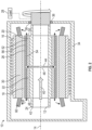
FIG. 1 is a cross-sectional view of an embodiment of an electric machine; -
FIG. 2 is a cross-sectional view of an embodiment of an electric machine operated as a motor; -
FIG. 3 is another cross-sectional view of an embodiment of an electric machine; and -
FIG. 4 is yet another cross-sectional view of an embodiment of an electric machine. - A detailed description of one or more embodiments of the disclosed apparatus and method are presented herein by way of exemplification and not limitation with reference to the Figures.
- Illustrated in
FIG. 1 is an embodiment of anelectric machine 10. Theelectric machine 10 includes arotor 12 which is rotatable about a machinecentral axis 14. Theelectric machine 10 further includes astator 16 surrounding therotor 12 and positioned radially outboard of therotor 12. Therotor 12 and thestator 16 define anair gap 18. While in the illustrated embodiment thestator 16 is located radially outboard of therotor 12, one skilled in the art will readily appreciate that the present disclosure may be readily applied to other machine configurations, such as configurations where therotor 12 is located radially outboard of thestator 16. - The
rotor 12 includes arotor core 20 and a plurality ofpermanent magnets 22 arrayed in therotor core 20. In some embodiments therotor core 20 includes a substantiallytubular rotor shaft 24 located at the machinecentral axis 14. Further, arotor sleeve 26 is located radially outboard of the plurality ofpermanent magnets 22 and circumferentially surrounding therotor core 20 to retain the plurality ofpermanent magnets 22 to therotor core 20. Therotor sleeve 26 at least partially defines theair gap 18 between therotor 12 and thestator 16. - In some embodiments, as illustrated in
FIG. 1 , theelectric machine 10 is operated as a generator in which therotor 12 is driven about the machinecentral axis 14 by a power source, schematically shown at 28. Rotation of therotor 12 relative to thestator 16 generates electromagnetic interaction between thepermanent magnets 22 andstator windings 30 of thestator 16, resulting in electrical power being generated at thestator windings 30. - Alternatively, the
electric machine 10 may be operated as a motor as illustrated inFIG. 2 . In such configurations, an electrical current may be applied to thestator windings 30 which urges rotation of therotor 12 about the machinecentral axis 14 due to electromagnetic interaction between thestator windings 30 and thepermanent magnets 22. Therotor shaft 24 may be connected to a mechanical load 32, and provides mechanical energy thereto. - The
rotor 12 and thestator 16 are at least partially contained in amachine housing 34, with therotor shaft 24 extending through ahousing opening 36 in themachine housing 34. One ormore sealing elements 38 may be located between therotor shaft 24 and themachine housing 34 to prevent leakage through thehousing opening 36. Therotor 12 is cooled via a flow of coolingfluid 40 entering via arotor cooling inlet 42 in thetubular rotor shaft 24. As shown inFIG. 3 , and with continued reference toFIG. 1 , the flow of coolingfluid 40 is directed into a shaft interior of therotor shaft 24, and radially outwardly along a plurality ofradial cooling channels 44, which in some embodiments are located in amid-stack plate 46 of therotor 12. In some embodiments, therotor core 20 is formed from a plurality of laminations stacked along the machinecentral axis 14, and themid-stack plate 46 is located between two axially-adjacent lamination of the plurality of laminations. - The
radial cooling channels 44 are located in therotor 12 at a location between a firstaxial end 48 and a secondaxial end 50 of therotor 12, remotely from the firstaxial end 48 and the secondaxial end 50, in an interior of therotor 12. In one embodiment, such as shown inFIG. 1 , theradial cooling channels 44 are located at an axial midpoint of therotor 12. As shown best inFIG. 3 , theradial cooling channels 44 are spaced circumferentially around therotor 12, and in some embodiments are equally circumferentially spaced. One skilled in the art will readily appreciate that the spacing, size and other characteristics of theradial cooling channels 44 may be varied to provide desired cooling properties. - Referring again to
FIG. 1 , the flow of coolingfluid 40 is urged through theradial cooling channels 44 via rotation of therotor 12 about the machinecentral axis 14. From theradial cooling channels 44 the flow of coolingfluid 40, such as oil, proceeds in an axial direction along a plurality ofsleeve cooling channels 52, which in some embodiments are defined between a radiallyouter surface 54 of therotor 12 and a radiallyinner surface 56 of therotor sleeve 26. The flow of coolingfluid 40 along theradial cooling channels 44 and thesleeve cooling channels 52 provides cooling of thepermanent magnets 22 and therotor sleeve 26, thus improving the performance of theelectric machine 10. - The flow of cooling
fluid 40 proceeds along the plurality ofsleeve cooling channels 52 both toward the firstaxial end 48 and the secondaxial end 50 and through asleeve channel outlet 58 into themachine housing 34. In some embodiments, the flow of coolingfluid 40 exiting thesleeve channel outlet 58 impinges or sprays onto end turns 60 of thestator windings 30 thus providing cooling to the end turns 60. - While in the embodiment of
FIG. 1 , onemid-stack plate 46 is utilized and includes theradial cooling channels 44, in other embodiments such as shown inFIG. 4 , the rotor includes multiplemid-stack plates 46 each having a plurality of radial cooling channels. In some embodiments, the firstradial cooling channels 44a of a firstmid-stack plate 46a are circumferentially offset from secondradial cooling channels 44b of a secondmid-stack plate 46b to provide even distribution of the flow of coolingfluid 40 throughout therotor 12. - The cooling arrangements disclosed herein including the
radial cooling channels 44 located along therotor 12 between the firstaxial end 48 and the secondaxial end 50 and thesleeve cooling channels 52, provides needed cooling to thepermanent magnets 22 and therotor sleeve 26 thus improving performance of therotor 12 and theelectric machine 10. This improves the power to weight ratio of theelectric machine 10 when compared to other cooling schemes and improves reliability of the electric machine due to the reduced operating temperatures. - The term "about" is intended to include the degree of error associated with measurement of the particular quantity based upon the equipment available at the time of filing the application.
- The terminology used herein is for the purpose of describing particular embodiments only and is not intended to be limiting of the present disclosure. As used herein, the singular forms "a", "an" and "the" are intended to include the plural forms as well, unless the context clearly indicates otherwise. It will be further understood that the terms "comprises" and/or "comprising," when used in this specification, specify the presence of stated features, integers, steps, operations, elements, and/or components, but do not preclude the presence or addition of one or more other features, integers, steps, operations, element components, and/or groups thereof.
- While the present disclosure has been described with reference to an exemplary embodiment or embodiments, it will be understood by those skilled in the art that various changes may be made and equivalents may be substituted for elements thereof without departing from the scope of the present disclosure. In addition, many modifications may be made to adapt a particular situation or material to the teachings of the present disclosure without departing from the essential scope thereof. Therefore, it is intended that the present disclosure not be limited to the particular embodiment disclosed as the best mode contemplated for carrying out this present disclosure, but that the present disclosure will include all embodiments falling within the scope of the claims.
Claims (15)
- An electric machine, comprising:a stator (16) including a stator winding (30); anda rotor (12)configured to rotate about a machine central axis and electromagnetically interactive with the stator (16) across an air gap between the rotor (12)and the stator (16), the rotor (12)including:a rotor core (20);a plurality of permanent magnets disposed at the rotor core (20);a rotor sleeve (26) enclosing the rotor core (20) and the plurality of permanent magnets;one or more sleeve cooling channels disposed between a radially outer surface of the rotor core (20) and a radially inner surface of the rotor sleeve (26) and extending axially along a length of the rotor; andone or more radial cooling channels extending radially outwardly from an interior of the rotor core (20) to the one or more sleeve cooling channels, the one or more radial cooling channels configured to convey a flow of cooling fluid from the interior of the rotor core (20) to the one or more sleeve cooling channels.
- The electric machine of claim 1, wherein the one or more radial cooling channels are positioned in an axial interior of the rotor core (20) between a first axial end and a second axial end of the rotor core (20), and optionally wherein the one or more radial cooling channels are located at an axial midpoint of the rotor core (20).
- The electric machine of any preceding claim, wherein the flow of cooling fluid is directed into the one or more radial cooling channels from a hollow interior of a rotor shaft.
- The electric machine of any preceding claim, further comprising a mid-stack plate disposed in the rotor core (20), the one or more radial cooling channels formed in the mid-stack plate.
- The electric machine of any preceding claim, wherein the one or more radial cooling channels is a plurality of radial cooling channels circumferentially spaced apart in the rotor core (20), or wherein the one or more radial cooling channels is a plurality of radial cooling channels at two different axial locations of the rotor.
- The electric machine of any preceding claim, further comprising one or more sleeve cooling channel outlets at one or more axial ends of the one or more sleeve cooling channels, the one or more sleeve cooling channel outlets configured to direct the flow of cooling fluid toward an end turn of the stator winding (30).
- A rotor of an electric machine, comprising:a rotor core (20);a plurality of permanent magnets disposed at the rotor core (20);a rotor sleeve (26) enclosing the rotor core (20) and the plurality of permanent magnets;one or more sleeve cooling channels disposed between a radially outer surface of the rotor core (20) and a radially inner surface of the rotor sleeve (26) and extending axially along a length of the rotor; andone or more radial cooling channels extending radially outwardly from an interior of the rotor core (20) to the one or more sleeve cooling channels, the one or more radial cooling channels configured to convey a flow of cooling fluid from the interior of the rotor core (20) to the one or more sleeve cooling channels.
- The rotor of claim 7, wherein the one or more radial cooling channels are positioned in an axial interior of the rotor core (20) between a first axial end and a second axial end of the rotor core (20), and optionally wherein the one or more radial cooling channels are located at an axial midpoint of the rotor core (20).
- The rotor of claim 7 or 8, wherein the flow of cooling fluid is directed into the one or more radial cooling channels from a hollow interior of a rotor shaft.
- The rotor of any of claims 7 to 9, further comprising a mid-stack plate disposed in the rotor core (20), the one or more radial cooling channels formed in the mid-stack plate.
- The rotor of any of claims 7 to 10, wherein the one or more radial cooling channels is a plurality of radial cooling channels circumferentially spaced apart in the rotor core (20), or wherein the one or more radial cooling channels is a plurality of radial cooling channels at two different axial locations of the rotor.
- The rotor of claim 9, further comprising one or more sleeve cooling channel outlets at one or more axial ends of the one or more sleeve cooling channels, the one or more sleeve cooling channel outlets configured to direct the flow of cooling fluid toward an end turn of a stator winding (30) of the electric machine.
- A method of cooling a rotor of a permanent magnet electric machine, comprising:directing a flow of cooling fluid into an interior of a rotor core (20) of the rotor;urging the flow of cooling fluid radially outwardly through one or more radial cooling channels defined in the rotor core (20); anddirecting the flow of cooling fluid from the one or more radial cooling channels along one or more sleeve cooling channels extending in an axial direction between the rotor core (20) and a rotor sleeve (26) surrounding the rotor core (20).
- The method of claim 13, wherein the one or more radial cooling channels are positioned in an axial interior of the rotor core (20) between a first axial end and a second axial end of the rotor core (20).
- The method of claim 13 or 14, wherein the one or more radial cooling channels are formed in a mid-stack plate disposed in the rotor core (20), or . wherein the one or more radial cooling channels is a plurality of radial cooling channels circumferentially spaced apart in the rotor core (20).
Applications Claiming Priority (1)
| Application Number | Priority Date | Filing Date | Title |
|---|---|---|---|
| US18/323,599 US12614940B2 (en) | 2023-05-25 | 2023-05-25 | Cooling of high-power permanent magnet machine rotor |
Publications (1)
| Publication Number | Publication Date |
|---|---|
| EP4472033A1 true EP4472033A1 (en) | 2024-12-04 |
Family
ID=91129531
Family Applications (1)
| Application Number | Title | Priority Date | Filing Date |
|---|---|---|---|
| EP24176451.3A Pending EP4472033A1 (en) | 2023-05-25 | 2024-05-16 | Cooling of high-power permanent magnet machine rotor |
Country Status (2)
| Country | Link |
|---|---|
| US (1) | US12614940B2 (en) |
| EP (1) | EP4472033A1 (en) |
Citations (4)
| Publication number | Priority date | Publication date | Assignee | Title |
|---|---|---|---|---|
| US20200280227A1 (en) * | 2019-03-01 | 2020-09-03 | Honda Motor Co., Ltd. | Rotor of rotary electric machine |
| US20200381968A1 (en) * | 2019-06-03 | 2020-12-03 | Honda Motor Co., Ltd. | Rotating electric machine |
| JP2020205725A (en) * | 2019-06-19 | 2020-12-24 | 本田技研工業株式会社 | Rotating machine |
| US20230006514A1 (en) * | 2019-12-12 | 2023-01-05 | Ihi Corporation | Rotation device |
Family Cites Families (7)
| Publication number | Priority date | Publication date | Assignee | Title |
|---|---|---|---|---|
| US6215212B1 (en) * | 1999-08-12 | 2001-04-10 | Hamilton Sundstrand Corporation | Shaftless rotor construction |
| US6727609B2 (en) * | 2001-08-08 | 2004-04-27 | Hamilton Sundstrand Corporation | Cooling of a rotor for a rotary electric machine |
| GB2430809B (en) | 2005-10-01 | 2010-02-17 | Turbo Genset Company Ltd | Self-cooled rotor for a high speed permanent magnet generator |
| JP5490103B2 (en) * | 2009-04-17 | 2014-05-14 | 株式会社日本自動車部品総合研究所 | Rotating electric machine |
| JP7071845B2 (en) | 2018-03-02 | 2022-05-19 | 本田技研工業株式会社 | Rotating electric machine |
| JP7061001B2 (en) | 2018-04-05 | 2022-04-27 | 株式会社Soken | Rotating electric machine unit |
| US11139719B2 (en) * | 2019-02-13 | 2021-10-05 | Hamilton Sundstrand Corporation | Dual fluid rotating shaft |
-
2023
- 2023-05-25 US US18/323,599 patent/US12614940B2/en active Active
-
2024
- 2024-05-16 EP EP24176451.3A patent/EP4472033A1/en active Pending
Patent Citations (4)
| Publication number | Priority date | Publication date | Assignee | Title |
|---|---|---|---|---|
| US20200280227A1 (en) * | 2019-03-01 | 2020-09-03 | Honda Motor Co., Ltd. | Rotor of rotary electric machine |
| US20200381968A1 (en) * | 2019-06-03 | 2020-12-03 | Honda Motor Co., Ltd. | Rotating electric machine |
| JP2020205725A (en) * | 2019-06-19 | 2020-12-24 | 本田技研工業株式会社 | Rotating machine |
| US20230006514A1 (en) * | 2019-12-12 | 2023-01-05 | Ihi Corporation | Rotation device |
Also Published As
| Publication number | Publication date |
|---|---|
| US12614940B2 (en) | 2026-04-28 |
| US20240396392A1 (en) | 2024-11-28 |
Similar Documents
| Publication | Publication Date | Title |
|---|---|---|
| EP3675332B1 (en) | Rotor for an electric machine | |
| CN108880111B (en) | Generator with enhanced stator cooling and reduced windage losses | |
| US12374945B2 (en) | Rotor for an electric machine having a radial cooling duct in the laminated core | |
| US8138642B2 (en) | Oil cooled generator | |
| EP1821392A2 (en) | High power generator with enhanced heat removal | |
| CN109209642B (en) | Electrical machine | |
| CN116231965A (en) | Cooling system for an electric machine | |
| WO2004070919A1 (en) | Rotary machine cooling system | |
| EP3713051B1 (en) | Rotor assembly and method of cooling | |
| CN102640400A (en) | Rotating directional coolant spray for electric machine | |
| EP4475403A1 (en) | Hybrid liquid and air cooling of high-power permanent magnet machine rotor | |
| EP4220907A1 (en) | Method and apparatus for cooling a rotor assembly | |
| EP1821393A2 (en) | High power generator with enhanced stator heat removal | |
| US11043867B2 (en) | Cooling of the end-windings of an electric generator | |
| JP2019161948A (en) | Rotary electric machine | |
| US4827165A (en) | Integrated diode package | |
| EP4084300A1 (en) | Cooling channels in a high-density motor | |
| CN1034781C (en) | Rotor of an electric motor with field current supply lines | |
| US12614940B2 (en) | Cooling of high-power permanent magnet machine rotor | |
| EP4443713A1 (en) | Electrical machine having a lead retention assembly | |
| EP3070816A1 (en) | Method and assembly for cooling an electric machine | |
| EP4220896A1 (en) | A rotor assembly and method for an electric machine | |
| US11705782B2 (en) | Electric motor cooling with oscillating heat pipes | |
| WO2024132522A1 (en) | Rotor for an electric machine and electric machine | |
| CN117616667A (en) | motor |
Legal Events
| Date | Code | Title | Description |
|---|---|---|---|
| PUAI | Public reference made under article 153(3) epc to a published international application that has entered the european phase |
Free format text: ORIGINAL CODE: 0009012 |
|
| STAA | Information on the status of an ep patent application or granted ep patent |
Free format text: STATUS: THE APPLICATION HAS BEEN PUBLISHED |
|
| AK | Designated contracting states |
Kind code of ref document: A1 Designated state(s): AL AT BE BG CH CY CZ DE DK EE ES FI FR GB GR HR HU IE IS IT LI LT LU LV MC ME MK MT NL NO PL PT RO RS SE SI SK SM TR |
|
| STAA | Information on the status of an ep patent application or granted ep patent |
Free format text: STATUS: REQUEST FOR EXAMINATION WAS MADE |
|
| 17P | Request for examination filed |
Effective date: 20250604 |