EP4472022A1 - Unterbrechungsfreie stromversorgung, steuerverfahren und stromversorgungssystem - Google Patents
Unterbrechungsfreie stromversorgung, steuerverfahren und stromversorgungssystem Download PDFInfo
- Publication number
- EP4472022A1 EP4472022A1 EP23206569.8A EP23206569A EP4472022A1 EP 4472022 A1 EP4472022 A1 EP 4472022A1 EP 23206569 A EP23206569 A EP 23206569A EP 4472022 A1 EP4472022 A1 EP 4472022A1
- Authority
- EP
- European Patent Office
- Prior art keywords
- power supply
- circuit
- charge
- voltage
- bus capacitor
- Prior art date
- Legal status (The legal status is an assumption and is not a legal conclusion. Google has not performed a legal analysis and makes no representation as to the accuracy of the status listed.)
- Pending
Links
Images

Classifications
-
- H—ELECTRICITY
- H02—GENERATION; CONVERSION OR DISTRIBUTION OF ELECTRIC POWER
- H02J—ELECTRIC POWER NETWORKS; CIRCUIT ARRANGEMENTS OR SYSTEMS FOR SUPPLYING OR DISTRIBUTING ELECTRIC POWER; SYSTEMS FOR STORING ELECTRIC ENERGY
- H02J9/00—Circuit arrangements for emergency or stand-by power supply, e.g. for emergency lighting
- H02J9/04—Circuit arrangements for emergency or stand-by power supply, e.g. for emergency lighting in which the distribution system is disconnected from the normal source and connected to a standby source
- H02J9/06—Circuit arrangements for emergency or stand-by power supply, e.g. for emergency lighting in which the distribution system is disconnected from the normal source and connected to a standby source with automatic change-over, e.g. UPS systems
- H02J9/062—Circuit arrangements for emergency or stand-by power supply, e.g. for emergency lighting in which the distribution system is disconnected from the normal source and connected to a standby source with automatic change-over, e.g. UPS systems for AC powered loads
-
- H—ELECTRICITY
- H02—GENERATION; CONVERSION OR DISTRIBUTION OF ELECTRIC POWER
- H02J—ELECTRIC POWER NETWORKS; CIRCUIT ARRANGEMENTS OR SYSTEMS FOR SUPPLYING OR DISTRIBUTING ELECTRIC POWER; SYSTEMS FOR STORING ELECTRIC ENERGY
- H02J7/00—Circuit arrangements for charging or discharging batteries or for supplying loads from batteries
- H02J7/34—Parallel operation in networks using both storage and other DC sources, e.g. providing buffering
- H02J7/342—The other DC source being a battery actively interacting with the first one, i.e. battery to battery charging
-
- H—ELECTRICITY
- H02—GENERATION; CONVERSION OR DISTRIBUTION OF ELECTRIC POWER
- H02J—ELECTRIC POWER NETWORKS; CIRCUIT ARRANGEMENTS OR SYSTEMS FOR SUPPLYING OR DISTRIBUTING ELECTRIC POWER; SYSTEMS FOR STORING ELECTRIC ENERGY
- H02J7/00—Circuit arrangements for charging or discharging batteries or for supplying loads from batteries
- H02J7/02—Circuit arrangements for charging or discharging batteries or for supplying loads from batteries for charging batteries from AC mains by converters
- H02J7/04—Regulation of charging current or voltage
-
- H—ELECTRICITY
- H02—GENERATION; CONVERSION OR DISTRIBUTION OF ELECTRIC POWER
- H02J—ELECTRIC POWER NETWORKS; CIRCUIT ARRANGEMENTS OR SYSTEMS FOR SUPPLYING OR DISTRIBUTING ELECTRIC POWER; SYSTEMS FOR STORING ELECTRIC ENERGY
- H02J7/00—Circuit arrangements for charging or discharging batteries or for supplying loads from batteries
- H02J7/34—Parallel operation in networks using both storage and other DC sources, e.g. providing buffering
- H02J7/345—Parallel operation in networks using both storage and other DC sources, e.g. providing buffering using capacitors as storage or buffering devices
-
- H—ELECTRICITY
- H02—GENERATION; CONVERSION OR DISTRIBUTION OF ELECTRIC POWER
- H02J—ELECTRIC POWER NETWORKS; CIRCUIT ARRANGEMENTS OR SYSTEMS FOR SUPPLYING OR DISTRIBUTING ELECTRIC POWER; SYSTEMS FOR STORING ELECTRIC ENERGY
- H02J7/00—Circuit arrangements for charging or discharging batteries or for supplying loads from batteries
- H02J7/865—Battery or charger load switching, e.g. concurrent charging and load supply
-
- H—ELECTRICITY
- H02—GENERATION; CONVERSION OR DISTRIBUTION OF ELECTRIC POWER
- H02J—ELECTRIC POWER NETWORKS; CIRCUIT ARRANGEMENTS OR SYSTEMS FOR SUPPLYING OR DISTRIBUTING ELECTRIC POWER; SYSTEMS FOR STORING ELECTRIC ENERGY
- H02J9/00—Circuit arrangements for emergency or stand-by power supply, e.g. for emergency lighting
- H02J9/04—Circuit arrangements for emergency or stand-by power supply, e.g. for emergency lighting in which the distribution system is disconnected from the normal source and connected to a standby source
- H02J9/06—Circuit arrangements for emergency or stand-by power supply, e.g. for emergency lighting in which the distribution system is disconnected from the normal source and connected to a standby source with automatic change-over, e.g. UPS systems
- H02J9/061—Circuit arrangements for emergency or stand-by power supply, e.g. for emergency lighting in which the distribution system is disconnected from the normal source and connected to a standby source with automatic change-over, e.g. UPS systems for DC powered loads
-
- H—ELECTRICITY
- H02—GENERATION; CONVERSION OR DISTRIBUTION OF ELECTRIC POWER
- H02J—ELECTRIC POWER NETWORKS; CIRCUIT ARRANGEMENTS OR SYSTEMS FOR SUPPLYING OR DISTRIBUTING ELECTRIC POWER; SYSTEMS FOR STORING ELECTRIC ENERGY
- H02J9/00—Circuit arrangements for emergency or stand-by power supply, e.g. for emergency lighting
- H02J9/04—Circuit arrangements for emergency or stand-by power supply, e.g. for emergency lighting in which the distribution system is disconnected from the normal source and connected to a standby source
- H02J9/06—Circuit arrangements for emergency or stand-by power supply, e.g. for emergency lighting in which the distribution system is disconnected from the normal source and connected to a standby source with automatic change-over, e.g. UPS systems
- H02J9/068—Electronic means for switching from one power supply to another power supply, e.g. to avoid parallel connection
-
- H—ELECTRICITY
- H02—GENERATION; CONVERSION OR DISTRIBUTION OF ELECTRIC POWER
- H02J—ELECTRIC POWER NETWORKS; CIRCUIT ARRANGEMENTS OR SYSTEMS FOR SUPPLYING OR DISTRIBUTING ELECTRIC POWER; SYSTEMS FOR STORING ELECTRIC ENERGY
- H02J2207/00—Details of circuit arrangements for charging or discharging batteries or supplying loads from batteries
- H02J2207/20—Charging or discharging characterised by the power electronics converter
-
- H—ELECTRICITY
- H02—GENERATION; CONVERSION OR DISTRIBUTION OF ELECTRIC POWER
- H02J—ELECTRIC POWER NETWORKS; CIRCUIT ARRANGEMENTS OR SYSTEMS FOR SUPPLYING OR DISTRIBUTING ELECTRIC POWER; SYSTEMS FOR STORING ELECTRIC ENERGY
- H02J2207/00—Details of circuit arrangements for charging or discharging batteries or supplying loads from batteries
- H02J2207/50—Charging of capacitors, supercapacitors, ultra-capacitors or double layer capacitors
Definitions
- the present application relates to the field of electric power, and in particular to an uninterruptible power supply, a control method and a power supply system.
- An uninterruptible power supply is a device that replaces a grid to supply power to a load without interruption when the grid malfunctions, so as to maintain the normal operation of the load.
- the uninterruptible power supply is connected to the grid and the load, and monitors an operation status of the grid.
- the uninterruptible power supply supplies electric energy provided by the grid to the load.
- the uninterruptible power supply controls its internal battery pack to discharge, and supplies electric energy outputted by the battery pack to the load.
- the uninterruptible power supply is equipped with a bus capacitor.
- a voltage across the bus capacitor is approximately equal to zero, and a difference between the voltage across the bus capacitor and the grid voltage is too large.
- a rectification circuit in the uninterruptible power supply or a special rectification circuit generally pre-charges the bus capacitor so as to start the uninterruptible power supply.
- the electric energy transmitted on the grid is generally converted into DC electric energy through an uncontrollable switch device to charge the bus capacitor. Therefore, the pre-charge voltage of the bus capacitor is limited by an amplitude of the grid voltage.
- the difference between the voltage across the bus capacitor and the grid voltage may be too large due to fluctuation of the output voltage of the grid and the power supply of the load inside the uninterruptible power supply, resulting in failure of start of the uninterruptible power supply.
- contacts of switch devices between the uninterruptible power supply and the grid are conglutinated, thus failing to disconnect the uninterruptible power supply from the grid, and resulting in damage to the uninterruptible power supply.
- An uninterruptible power supply, a control method and a power supply system are provided according to the present application, to normally start the uninterruptible power supply and secure a switch device.
- an uninterruptible power supply includes at least a first rectification circuit, a bus capacitor, a second rectification circuit, a first switch circuit, a charge-discharge circuit.
- the first rectification circuit is connected to the charge-discharge circuit, for connecting to an alternating current power supply.
- the charge-discharge circuit is connected to the bus capacitor.
- the first switch circuit is connected to the second rectification circuit, for connecting to the alternating current power supply.
- the uninterruptible power supply is generally equipped with a battery pack or connected to a battery pack.
- the charge-discharge circuit is connected between the battery pack and the bus capacitor, and is configured to charge or discharge the battery pack, so as to continue to supply power to the load after the alternating current power supply fails, thereby realizing the continuous power supply of the uninterruptible power supply.
- the charge-discharge circuit can regulate the voltage.
- the charge-discharge circuit performs voltage regulation and the first rectification circuit performs rectification, rectifying and regulating the electric energy outputted by the alternating current power supply.
- the bus capacitor is charged until the voltage across the bus capacitor reaches the first voltage. Since boosted by the charge-discharge circuit, the charging voltage of the bus capacitor is not limited by the voltage amplitude of the alternating current power supply, and compensates for the voltage drop caused by the internal load operation of the uninterruptible power supply and the voltage fluctuation of the alternating current power supply.
- the first switch circuit is controlled to be on, the second rectification circuit is controlled to operate, the uninterruptible power supply is started normally and supplies power to the load connected to the bus capacitor, and the first switch circuit is protected.
- a battery pack is arranged inside the uninterruptible power supply.
- the battery pack is connected to the charge-discharge circuit, and is configured to output the stored voltage to the charge-discharge circuit.
- the charge-discharge circuit is further configured to: charge the bus capacitor after boosting the voltage outputted by the battery pack until the voltage across the bus capacitor reaches the first voltage.
- the charge-discharge circuit pre-charges the bus capacitor after boosting the electric energy stored in the battery pack, thereby pre-charging the bus capacitor flexibly.
- the uninterruptible power supply also includes a second switch circuit connected between the battery pack and the charge-discharge circuit, and a third switch circuit connected between the first rectification circuit and the charge-discharge circuit.
- the second switch circuit is configured to control a connection between the battery pack and the charge-discharge circuit
- the third switch circuit is configured to control a connection between the first rectification circuit and the charge-discharge circuit.
- the second switch circuit is connected between the battery pack and the charge-discharge circuit, and when the second switch circuit is on, a charging circuit between the battery pack and the bus capacitor is formed.
- the third switch circuit is connected between the first rectification circuit and the charge-discharge circuit, and when the third switch circuit is on, a charging circuit between the first rectification circuit and the bus capacitor is formed. Therefore, by switching on the second switch circuit or the third switch circuit, the pre-charging path of the bus capacitor is selected.
- the uninterruptible power supply also includes a first controller.
- the first controller is connected to the charge-discharge circuit and is configured to control the charge-discharge circuit to charge the bus capacitor after boosting the voltage outputted by the battery pack or the first rectification circuit.
- the first controller is connected to the first switch circuit, the second switch circuit and the third switch circuit, and is configured to switch on the first switch circuit, the second switch circuit and the third switch circuit.
- the uninterruptible power supply also includes a second controller.
- the second controller connected to the first switch circuit, the second switch circuit and the third switch circuit, and configured to switch on the first switch circuit, the second switch circuit and the third switch circuit.
- the uninterruptible power supply also includes a voltage sensor connected to the bus capacitor and configured to measure the voltage across the bus capacitor.
- the uninterruptible power supply in case that the uninterruptible power supply is connected to an alternating current load, in order to supply power to the alternating current load, the uninterruptible power supply also includes an inverter circuit connected to the bus capacitor and configured to convert the voltage across the bus capacitor into a power supply voltage for a downstream load, and supply power to the load.
- a power supply system in a second aspect, includes a power supply, an alternating current power supply, and the uninterruptible power supply in the first aspect of embodiments of the present application.
- the uninterruptible power supply is connected to the load and the alternating current power supply, and is configured to: convert a voltage outputted by the alternating current power supply into a power supply voltage of the load and supply power to the load; and convert electric energy stored in a battery pack into the power supply voltage of the load and supply power to the load when the power supply malfunctions.
- a method for controlling the uninterruptible power supply is provided according to an embodiment of the present application.
- the method is applied to the uninterruptible power supply according to the first aspect of the embodiment of the present application, and is performed by the control device in the uninterruptible power supply.
- the method includes: controlling the charge-discharge circuit to charge the bus capacitor; detecting the voltage across the bus capacitor; switching on the first switch circuit when it is determined that the voltage across the bus capacitor reaches the first voltage; and controlling the charge-discharge circuit to stop charging the bus capacitor, and controlling the second rectification circuit to operate.
- controlling the charge-discharge circuit to charge the bus capacitor includes: controlling the charge-discharge circuit to charge the bus capacitor after boosting a voltage stored in a battery pack; or controlling the charge-discharge circuit to charge the bus capacitor after boosting the voltage outputted by the first rectification circuit.
- the method also includes: charging the input capacitor until the voltage across the input capacitor reaches a set voltage before the controlling the charge-discharge circuit to charge the bus capacitor, if an input capacitor is arranged in the charge-discharge circuit and a voltage across the input capacitor is zero.
- the voltage across the input capacitor is first charged to the set voltage so that the charge-discharge circuit operates stably, and then the charge-discharge circuit is controlled to boost the voltage so that the charge-discharge circuit operates normally .
- the method also includes: switching on a second switch circuit or a third switch circuit before the controlling the charge-discharge circuit to charge said bus capacitor; and switching off the second switch circuit or the third switch circuit after the controlling the charge-discharge circuit to stop charging the bus capacitor.
- the second switch circuit or the third switch circuit is controlled to be on, so as to connect the charge-discharge circuit to the charging power supply.
- the charge-discharge circuit stops charging the bus capacitor, the charge-discharge circuit is disconnected from the charging power supply by switching off the second switch circuit and the third switch circuit, in order to reduce circuit loss and component loss of the circuit.
- a computer storage medium is provided according to an embodiment of the present application.
- a computer program is stored in the computer storage medium.
- the uninterruptible power supply performs the method for controlling the uninterruptible power supply in the third aspect of the embodiments of the present application.
- an uninterruptible power supply is generally configured in a data center in order to prevent the loss of important data when the data center suddenly loses power.
- the uninterruptible power supply supplies power when the power grid or other power supply malfunctions, and the data center can store important data during this period of time.
- Vehicles include but are not limited to: vehicles, robots, lighting equipment, industrial equipment, smart factory equipment, etc.
- Vehicles according to embodiments of the present application may include one or more different types of transports or movable objects that operate or move on land (e.g., roads, streets, railways, etc.), water (e.g., waterways, rivers, oceans, etc.) or space.
- the transport may include trains, subways, airplanes, boats, aircraft, or other types of means of transportation or movable objects.
- An uninterruptible power supply, a control method and a power supply system are provided according to embodiments of the present application, to normally start the uninterruptible power supply and secure the uninterruptible power supply.
- the inventive concept of the present application is summarized as follows.
- the charge-discharge circuit performs boost processing to pre-charge the bus capacitor, thereby increasing the pre-charge voltage of the bus capacitor to compensate for the voltage drop of the bus capacitor caused by the fluctuation in the AC power supply voltage and the power supply to an internal load. Therefore, the voltage drop between the AC power supply and the bus capacitor is reduced, thus ensuring the uninterruptible power supply to be started successfully, and securing the components of the first switch circuit.
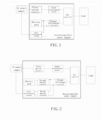
- FIG 1 is a schematic structural diagram of the uninterruptible power supply according to an embodiment of the present application.
- the uninterruptible power supply includes at least a first rectification circuit, a charge-discharge circuit, a bus capacitor, a first switch circuit and a second rectification circuit.
- the uninterruptible power supply shown in FIG 1 is merely an example.
- the uninterruptible power supply may have more or fewer components than shown in FIG 1 , may combine two or more components, or may have a different configuration of components.
- the various components shown in FIG 1 may be implemented in hardware, software, or a combination of hardware and software including one or more signal processing and/or application specific integrated circuits.
- the input terminal of the second rectification circuit is configured to be connected to the AC power supply via the first switch circuit.
- the output terminal of the second rectification circuit is connected to the bus capacitor.
- the second rectification circuit converts the AC outputted by the AC power supply into DC, and stabilizes the DC via the bus capacitor to supply power to a downstream load.
- the uninterruptible power supply is generally configured with or connected to a battery pack, and the battery pack is connected to the bus capacitor via the charge-discharge circuit.
- the charge-discharge circuit may have a charging function and a discharging function.
- a terminal of the charge-discharge circuit connected to the bus capacitor functions as the input terminal, and a terminal of the charge-discharge circuit connected to the battery pack functions as the output terminal.
- the charge-discharge circuit performs charging, i.e., converts the voltage of the bus capacitor into the charging voltage of the battery pack, and charges the battery pack.
- a terminal of the charge-discharge circuit connected to the battery pack functions as the input terminal, and a terminal of the charge-discharge circuit connected to the bus capacitor functions as the output terminal.
- the charge-discharge circuit performs discharging, i.e., converts the electric energy stored in the battery pack and outputs the converted electric energy to the bus capacitor, and supplies power to the load after the voltage is stabilized by the bus capacitor, so as to meet the power supply demand of the load connected to the uninterruptible power supply.
- the AC power supply may be a grid or other power supply.
- the grid may be, but is not limited to: a utility grid, a micro grid, a household grid, an industrial grid, and the like.
- Other power supply may be, but is not limited to: renewable energy power generation systems, diesel generators, etc.
- the second rectification circuit includes multiple switch devices.
- the switch device may be a controllable switch device or an uncontrollable switch device.
- the bus capacitor inside the uninterruptible power supply has already stored electric energy, and this electric energy can be supplied to the control device of the controllable switch device. Therefore, the present application preferably adopts the controllable switch device in order to improve the rectification efficiency and power factor of the second rectification circuit.
- the second rectification circuit is connected to the AC power supply via the first switch circuit.
- the first switch circuit controls the connection between the uninterruptible power supply and the external AC power supply.
- the first switch circuit disconnects the uninterruptible power supply from the AC power supply to prevent the failure of the AC power supply from affecting the normal operation of the uninterruptible power supply.
- the first switch circuit reconnects the uninterruptible power supply to the AC power supply, so that the uninterruptible power supply can operate normally.
- the uninterruptible power supply when the AC power supply resumes normal operation or when the uninterruptible power supply is firstly installed, the voltage across the bus capacitor is approximately equal to zero. If the first switch circuit is directly controlled to be switched on, a contact of the switch device inside the first switch circuit may be conglutinated due to the excessive voltage difference between the alternating current power supply and the bus capacitor, and the uninterruptible power supply may fail to start. In order to reduce the voltage difference between the alternating current power supply and the bus capacitor, the uninterruptible power supply according to the embodiment of the present application pre-charges the bus capacitor via the first rectification circuit and the charge-discharge circuit.
- the input terminal of the first rectification circuit is configured to be connected to the AC power supply.
- the output terminal of the first rectification circuit is connected to the bus capacitor via the charge-discharge circuit.
- the first rectification circuit acquires power from the AC power supply, rectifies the output voltage of the AC power supply, and then outputs the rectified voltage to the charge-discharge circuit.
- the charge-discharge circuit pre-charges the bus capacitor after boosting the voltage outputted by the first rectification circuit. When the voltage across the bus capacitor reaches the first voltage, the charge-discharge circuit stops charging the bus capacitor.
- the first voltage may be greater than or equal to a peak voltage of the AC power supply, thereby compensating the voltage drop caused by the voltage fluctuation of the AC power supply and internal devices, and reducing the voltage difference between the AC power supply and the bus capacitor. Then, the first switch circuit is controlled to be switched on, and the second rectification circuit is controlled to operate, and therefore the uninterruptible power supply can operate normally.
- multiple switch devices are arranged in the charge-discharge circuit.
- the multiple switch devices are switched on or off to modify the transformation ratio of the charge-discharge circuit, thereby regulating the charging voltage of the bus capacitor.
- the charging voltage of the bus capacitor is not limited by the amplitude of the AC power supply. Therefore, the voltage difference between the bus capacitor and the AC power supply can be reduced after the pre-charging, and the uninterruptible power supply can be successfully started.
- the voltage drop generated by the internal load supplied by the uninterruptible power supply is determined based on the parameters of the internal load of the uninterruptible power supply, and the voltage amplitude of the first voltage is determined based on the voltage drop.
- the internal load may be a load that is to be powered during the startup process of the uninterruptible power supply, for example, the auxiliary source and the controller of the charge-discharge circuit.
- the above parameters include but not limited to the rated power of the load and the voltage drop generated on the internal line.
- the uninterruptible power supply may be provided with a sensor or connected to an external sensor.
- the sensor is connected to the AC power supply, and monitors the change in the voltage amplitude of the AC power supply. Therefore, the voltage amplitude of the first voltage may be determined based on the change in the voltage amplitude of the AC power supply and the parameters of the internal load of the uninterruptible power supply.
- the uninterruptible power supply pre-charges the bus capacitor via boost processing by the charge-discharge circuit.
- the charge-discharge circuit is also connected to the battery pack which can store electrical energy. Therefore, in the embodiment of the present application, the electric energy stored in the battery pack may also be used to pre-charge the bus capacitor. Details about the pre-charging of the bus capacitor are described below in conjunction with the embodiments.
- the battery pack pre-charges the bus capacitor via the charge-discharge circuit.
- the battery pack is connected to the bus capacitor via the charge-discharge circuit, and acquires electric energy for pre-charging the bus capacitor from an external power supply.
- the pre-charged battery pack is connected to the charge-discharge circuit through corresponding ports so as to provide charging power to the bus capacitor.
- the battery pack in the uninterruptible power supply is also connected to other external power supplies, and the other external power supplies charges the battery pack, so that the charged battery pack can meet the pre-charging requirements of the bus capacitor.
- the AC power supply pre-charges the bus capacitor.
- the AC power supply charges the bus capacitor.
- the first rectification circuit is connected to an external AC power supply through a power line and a port, and acquires power from the AC power supply.
- the acquired electric energy is rectified by the first rectification circuit and boosted by the charge-discharge circuit sequentially, and is outputted to the bus capacitor for pre-charging the bus capacitor.
- multiple switch devices are arranged in the first rectification circuit. If neither the bus capacitor nor the battery pack stores electric energy, the switch devices in the first rectification circuit are uncontrollable switch devices in order to prevent the controllable switch device from malfunction due to power failure of the control device.
- multiple switch devices are arranged in the first rectification circuit.
- the switch devices in the first rectification circuit may be controllable or uncontrollable, if the battery pack or bus capacitor in the uninterruptible power supply already stores electric energy.
- the first rectification circuit acquires electric energy from an AC power supply and pre-charges the bus capacitor.
- a current limiting resistor is arranged in the first rectification circuit to reduce the amplitude of the current outputted by the first rectification circuit.
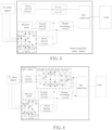
- the uninterruptible power supply may further include a second switch circuit and a third switch circuit.
- the second switch circuit is connected between the charge-discharge circuit and the battery pack
- the third switch circuit is connected between the first rectification circuit and the charge-discharge circuit.
- the third switch circuit When the third switch circuit is turned on, the first rectification circuit is connected to the bus capacitor via the charge-discharge circuit, and a pre-charging circuit of the bus capacitor is formed. Therefore, the pre-charging power supply is selected for the bus capacitor by turning on the second switch circuit and the third switch circuit.
- the uninterruptible power supply is equipped with a sensor or connected to an external sensor.
- the sensor measures the voltage across the bus capacitor, and controls the charge-discharge circuit to end the pre-charging of the bus capacitor based on the voltage across the bus capacitor.
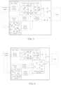
- the first rectification circuit is provided with an AC terminal and a DC terminal.
- the AC terminal of the first rectification circuit single-phase or three-phase, and is for receiving single-phase AC power or three-phase AC power outputted by the AC power supply.
- the DC terminal of the first rectification circuit is connected to the third switch circuit for outputting the rectified DC power.
- the AC terminal of the first rectification circuit is provided with at least two ports, and the specific number of ports depends on the type of AC power transmitted by the AC power supply. For example, if the AC power supply transmit three-phase AC power in a three-phase four-wire mode, the AC terminal of the first rectification circuit is provided with four ports respectively connected to three phase wires and a neutral wire.
- the first rectification circuit may include at least two bridge arms. Two switch devices are connected in series on each bridge arm. A middle node of each bridge arm is connected to a port at the AC end. The first terminal of each bridge arm is connected to the port receiving the high level at the first end of the third switch circuit. The second terminal of each bridge arm is connected to the port receiving the low level at the first end of the third switch circuit.
- the number of bridge arms in the first rectification circuit depends on the type of AC transmitted by the AC power supply.
- the middle node of each bridge arm constitutes the AC end of the first rectification circuit.
- the first and second terminals of each bridge arm form the DC end of the first rectification circuit.
- the two switch devices connected in series on each bridge arm may be controllable switch devices or uncontrollable switch devices.
- the switch device in the first rectification circuit preferably adopts the uncontrollable switch device.
- the AC power supply outputs three-phase AC power.
- the first rectification circuit includes three bridge arms.
- the first bridge arm includes diodes D1 and D2 connected in series.
- the second bridge arm includes diodes D3 and D4 connected in series.
- the third bridge arm includes diodes D5 and D6 connected in series.
- the middle node of the diodes D1 and D2 is connected to the port receiving the A-phase AC.
- the middle node of the diodes D3 and D4 is connected to the port for receiving the B-phase AC.
- the middle node of the diodes D5 and D6 is connected to the port receiving the C-phase AC.
- the first terminals of the diodes D1, D3 and D5 are connected to the port receiving the high level at the first end of the third switch circuit.
- the second terminals of the diodes D2, D4 and D6 are connected to the port receiving the low level at the first end of the third switch circuit.
- the A-phase AC, B-phase AC and C-phase AC are each single-phase AC and constitute the three-phase AC.
- resistors R1 and R2 are current limiting resistors.
- the current limiting resistor R1 is connected between the first terminals of the bridge arms and the third switch circuit.
- the current limiting resistor R2 is connected between the second terminals of the bridge arms and the third switch circuit. The resistance of current limiting resistors R1 and R2 depends on the current limit of the connected devices.
- only one current limiting resistor is provided in the first rectification circuit.
- the current limiting resistor is connected between the switch device of the first rectification circuit and the first capacitor C1.
- the first rectification circuit may also adopt other structures.
- the first rectification circuit may be a single-phase uncontrollable bridge circuit for single-phase rectification.
- the second rectification circuit may have an input terminal and an output terminal.
- the AC end of the second rectification circuit is connected to an external AC power supply through the first switch circuit.
- the DC end of the second rectification circuit is connected to the bus capacitor.
- the AC end of the second rectification circuit is a single-phase AC end or a three-phase AC end, and is for receiving single-phase AC power or three-phase AC power outputted by the AC power supply.
- the AC end of the second rectification circuit includes at least two ports, and the specific number of ports depends on the type of AC power transmitted by the AC power supply.
- the second rectification circuit may be, but not limited to, a fully-controlled rectification circuit, a half-control rectification circuit and an uncontrollable rectification circuit, each of which have one or more circuit topologies.
- the details of the circuit topologies can be referred to the existing circuit structure with rectification function.
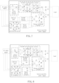
- the AC power supply outputs three-phase AC power.
- the second rectification circuit adopts the existing Vienna circuit topology.
- the first rectification circuit includes energy storage inductors L1 to L3, diodes D7 to D12, and controllable switches Q1 to Q6.
- the middle node of diodes D7 and D8 is connected to the energy storage inductor L1.
- the middle node of diodes D9 and D10 is connected to the energy storage inductor L2.
- the middle node of the diodes D11 and D12 is connected to the energy storage inductor L3.
- First terminals of the diodes D7, D9 and D11 are all connected to the first terminal of the bus capacitor.
- Second terminals of the diodes D8, D10 and D12 are all connected to the second terminal of the bus capacitor.
- One terminal of a branch formed by connecting the switch transistors Q1 and Q2 in series is connected to the middle node of the diodes D7 and D8, and the other terminal of the branch is connected to the middle node of the bus capacitor.
- One terminal of a branch formed by connecting the switch transistors Q3 and Q4 in series is connected to the middle node of the diodes D9 and D10, and the other terminal of the branch is connected to the middle node of the bus capacitor.
- One terminal of a branch formed by connecting the switch transistors Q5 and Q6 in series is connected to the middle node of the diodes D11 and D12, and the other terminal of the branch is connected to the middle node of the bus capacitor.
- the energy storage inductor L1 is connected to the port of the AC power supply outputting the A-phase AC power through the first switch circuit.
- the energy storage inductor L2 is connected to the port of the AC power supply outputting the B-phase AC power through the first switch circuit.
- the energy storage inductor L3 is connected to the port of the AC power supply outputting the C-phase AC power through the first switch circuit.
- a parasitic diode is provided to the switch device in the second rectification circuit or a diode is connected in parallel with the switch device.
- the switch device in the second rectification circuit may be an uncontrollable switch device.
- the first rectification circuit may also adopt other structures, which are not limited herein.
- the bus capacitor has a first terminal and a second terminal.
- the first terminal may be a terminal where the bus capacitor receives a high level.
- the second terminal may be a terminal where the bus capacitor receives a low level.
- At least one capacitor may be included in the bus capacitor.
- the first terminal of the capacitor is the first terminal of the bus capacitor
- the second terminal of the capacitor is the second terminal of the bus capacitor.
- the bus capacitor includes multiple capacitors, the multiple capacitors may be connected in series or in parallel.
- multiple capacitors in the bus capacitor are connected in parallel, first terminals of the multiple capacitors are connected to form the first terminal of the bus capacitor, and second terminals of the multiple capacitors are connected to form the second terminal of the bus capacitor.
- multiple capacitors in the bus capacitor are connected in series.
- the first terminal of a first capacitor in the multiple capacitors in series is the first terminal of the bus capacitor
- the second terminal of a last capacitor in the multiple capacitors in series is the second terminal of the bus capacitor.
- the bus capacitor includes a first capacitor C1 and a second capacitor C2 connected in series.
- the first terminal of the first capacitor C1 is the first terminal of the bus capacitor.
- the second terminal of the second capacitor C2 is the second terminal of the bus capacitor.
- bus capacitor structure is merely an example.
- the bus capacitor may adopt other structures.
- some capacitors may be connected in series and then connected in parallel, or some capacitors may be connected in parallel and then connected in series.
- the charge-discharge circuit has a first end and a second end.
- the first end of the charge-discharge circuit is connected to the battery pack through the second switch circuit, and is also connected to the first rectification circuit through the third switch circuit.
- the second end of the charge-discharge circuit is connected to the bus capacitor.
- the charge-discharge circuit charges and discharges the battery pack.
- the second end of the charge-discharge circuit serves as an input end
- the first end of the charge-discharge circuit serves as an output terminal
- the charge-discharge circuit performs charging.
- the charge-discharge circuit converts the voltage across the bus capacitor into the charging voltage of the battery pack, and charges the battery pack.
- the first end of the charge-discharge circuit serves as the input end
- the second end of the charge-discharge circuit serves as the output end
- the charge-discharge circuit performs discharging.
- the charge-discharge circuit converts the electric energy stored in the battery pack and outputs the converted electric energy to the bus capacitor.
- the electric energy after stabilized by the bus capacitor, is supplied to the load connected downstream of the bus capacitor.
- the charge-discharge circuit also boosts the electric energy stored in the battery pack or the electric energy outputted by the first rectification circuit to pre-charge the bus capacitor when the uninterruptible power supply is installed for the first time or the AC power supply fails.
- the charge-discharge circuit is but not limited to a boost circuit with a voltage boosting function or a Buck-Boost circuit with a voltage boosting function and a voltage reducing function.
- FIG 6 is a structural schematic diagram of the charge-discharge circuit.
- the charge-discharge circuit includes a third capacitor C3, a switch transistor Q7, a switch transistor Q8 and a switch transistor Q9, and energy storage inductors L4 and L5.
- the third capacitor C3 serves as an input capacitor of the charge-discharge circuit.
- a first terminal of the switch transistor Q7 is connected to a first terminal of the bus capacitor.
- a second terminal of the switch transistor Q7 is connected to the first terminal of the switch transistor Q8.
- a second terminal of the switch transistor Q8 is connected to a first terminal of the switch transistor Q9.
- a second terminal of the switch transistor Q9 is connected to a second terminal of the bus capacitor.
- a first terminal of the energy storage inductor L4 is connected to the first terminal of the third capacitor C3.
- a second terminal of the energy storage inductor L4 is connected to the second terminal of the switch transistor Q7.
- a first terminal of the energy storage inductor L5 is connected to the second terminal of the third capacitor C3.
- a second terminal of the energy storage inductor L5 is connected to the second terminal of the switch transistor Q8.
- the first terminal of the third capacitor C3 is connected to terminals of the second switch transistor circuit and the third switch transistor circuit, where the terminals each output a high level.
- the second terminal of the third capacitor C3 is connected to terminals of the second switch transistor circuit and the third switch transistor circuit, where the terminals each output a low level.
- the switch devices in the charge-discharge circuit are MOSFETs each equipped with a parasitic diode.
- the switch devices in the charge-discharge circuit are BJTs and IGBTs each equipped with no parasitic diode.
- the first rectification circuit rectifies the AC outputted by the AC power supply into DC.
- the DC is transmitted to the third capacitor C3 through the current limiting resistors R1 and R2. If the voltage across the third capacitor C3 is zero, the electric energy outputted by the second rectification circuit firstly charges the third capacitor C3, so that the charge-discharge circuit operates stably.
- the switch devices in the charge-discharge circuit are switched on, thereby boosting the voltage across the third capacitor C3.
- the second switch circuit is on, the charge-discharge circuit is switched on by switching on the switch transistor inside, and the electric energy stored in the battery pack is boosted to charge the bus capacitor.
- the switch transistors Q7 and Q9 are switched off.
- the second switch circuit or the third switch circuit is cut off to avoid waste of electric energy.
- the set voltage depends on parameters such as the power supply demand of the load and the inductive reactance of the energy storage inductor.
- the charge-discharge circuit also adopts other structures, for example, the circuit or chip that performs the boost function, and the present application is not limited here.
- the first switch circuit has a first terminal and a second terminal.
- the first terminal of the first switch circuit is configured to be connected the external AC power supply.
- the second terminal of the first switch circuit is connected to the second rectification circuit.
- the first switch circuit controls the connection between the AC power supply and the second rectification circuit.
- the first switch circuit includes at least one switches device, the number of switches device depends on the type of AC transmitted by the AC power supply.
- the switch device in the first switch circuit is a relay, in order to reduce the cost of the uninterruptible power supply.
- the first switch circuit includes three relays K1 to K3.
- One terminal of the relay K1 is connected to the phase wire transmitting the A-phase AC power in the AC power supply.
- the other terminal of the relay K1 is connected to the energy storage inductor L1.
- One terminal of the relay K2 is connected to the phase wire transmitting the B-phase AC power in the AC power supply.
- the other terminal of the relay K2 is connected to the energy storage inductor L2.
- One terminal of the relay K3 is connected to the phase wire transmitting the C-phase AC power in the AC power supply.
- the other terminal of the relay K3 is connected to the energy storage inductor L3.
- the switch device of the first switch circuit may be other switch devices besides the relay, which is not limited in the present application.
- the second switch circuit has a first end and a second end.
- the third switch circuit has a first end and a second end. The first end of the second switch circuit is connected with the battery pack. The second end of the first switch circuit is connected with the charge-discharge circuit. The first end of the third switch circuit is connected to the DC end of the first rectification circuit. The second end of the second switch circuit is connected to the charge-discharge circuit.
- the battery pack When the second switch circuit is on, the battery pack is connected to the charge-discharge circuit. When the second switch circuit is off, the battery pack is disconnected from the charge-discharge circuit.
- the third switch circuit When the third switch circuit is on, the first rectification circuit is connected to the charge-discharge circuit. When the third switch circuit is off, the first rectification circuit is disconnected from the charge-discharge circuit.
- the second switch circuit and the third switch circuit each include at least one switch device.
- the first switch circuit includes two relays K4 and K5, and the second switch circuit includes two relays K6 and K7.
- the relay K4 is connected between the positive pole of the battery pack and the first terminal of the third capacitor C3.
- the relay K5 is connected between the negative pole of the battery pack and the second terminal of the third capacitor C3.
- the relay K6 is connected between the current limiting resistor R1 and the first terminal of the third capacitor C3.
- the relay K7 is connected between the current limiting resistor R2 and the second terminal of the third capacitor C3.
- the battery pack is connected to the bus capacitor via the charge-discharge circuit, and the charging circuit between the battery pack and the bus capacitor is formed.
- the first rectification circuit is connected to the bus capacitor via the charge-discharge circuit, and the charging circuit between the first rectification circuit and the bus capacitor is formed.
- the second switch circuit is on when the relays K4 and K5 are on, and the second switch circuit is off when one or both of the relays K4 and K5 are off.
- the third switch circuit is on when the relays K6 and K7 are on, and the third switch circuit is off when one or both of the relays K6 and K7 are off.
- each of the second switch circuit and the third switch circuit includes only one relay, in order to reduce the cost of the uninterruptible power supply.
- the relay in the second switch circuit is connected between the positive pole of the battery pack and the first terminal of the third capacitor C3, or between the negative pole of the battery pack and the second terminal of the third capacitor C3.
- the relay in the third switch circuit is connected between the current limiting resistor R1 and the first terminal of the third capacitor C3, or between the current limiting resistor R2 and the second terminal of the third capacitor C3.
- the switch devices in the second switch circuit and the third switch circuit may be other switch devices besides the relays, which is not limited in the present application.
- the structures of the devices in the uninterruptible power supply and the pre-charging of the bus capacitor have been introduced above.
- the devices pre-charge the bus capacitor so as to compensate for the voltage drop caused by the voltage fluctuation of the AC power supply and the internal load power supply, thereby reducing the voltage difference between the bus capacitor and the AC power supply.
- the uninterruptible power supply can be started successfully and switch devices in the first switch circuit can be secured.
- the second rectification circuit connected between the AC power supply and the bus capacitor adopts devices with smaller sizes and lower costs. Therefore, the cost of the uninterruptible power supply is further reduced.
- the second rectification circuit is controlled to operate to rectify the power outputted by the AC power supply and supply power to the load connected downstream of the bus capacitor, so that the uninterruptible power supply operates stably.
- the bus capacitor directly supplies power to a DC load when the uninterruptible power supply is connected to the DC load.
- the uninterruptible power supply according to the embodiments of the present application further includes an inverter circuit. The inverter circuit is connected between the bus capacitor and the AC load, and converts the DC power on the bus capacitor into AC power to supply power to the AC load.
- the inverter circuit includes multiple bridge arms. Two switch devices are connected in series on each bridge arm. The number of bridge arms in the inverter circuit depends on the power supply demand of the AC load. For example, if the AC load requires single-phase AC power, the inverter circuit is an H-bridge composed of two bridge arms.
- the uninterruptible power supply according to the embodiments of the present application also includes a control device for switching on and off the switch device.
- the uninterruptible power supply further includes a first controller.
- the first controller is connected to the charge-discharge circuit, and is configured to control the charge-discharge circuit to boost the voltage outputted by the battery pack or the first rectification circuit to charge the bus capacitor.
- the first controller is connected to control terminals of the switch devices in the above circuit, and sends corresponding driving signals to the control terminals of the switch devices, so as to control the charge-discharge circuit to boost the voltage outputted by the battery pack or the first rectification circuit to charge the bus capacitor.
- the first controller is also connected to the first switch circuit, the second switch circuit and the third switch circuit.
- the first controller is also configured to switch on the first switch circuit, the second switch circuit and the third switch circuit, so as to select the way of pre-charging the bus capacitor, and control the connection between the uninterruptible power supply and the AC power supply.
- a switch is provided on a connecting line between the relay in the switch circuit and the power supply.
- the first controller is connected to the control terminal of the switch, and controls the connection of the relay to the power supply by controlling the state of the switch, thereby controlling the state of the relay.
- the first controller is also connected to the second rectification circuit, and is configured to control the second rectification circuit to perform rectifying and supply power to the load when the first switch circuit is on.
- the uninterruptible power supply further includes a second controller.
- the second controller is connected with the first switch circuit, the second switch circuit and the third switch circuit, and is configured to switch on the first switch circuit, the second switch circuit and the third switch circuit.
- the power supply system includes a load, a power supply and the aforementioned uninterruptible power supply.
- the uninterruptible power supply is connected to the load and the power supply, and is configured to convert the output voltage of the power supply into the supply voltage of the load and supply power to the load.
- the uninterruptible power supply is also configured to convert the electric energy stored in the battery pack into the supply voltage of the load and supply power to the load when the power supply fails.
- a method for controlling the uninterruptible power supply is also provided according to an embodiment of the present application.
- the method is applied to the uninterruptible power supply shown in FIG 1 to FIG 8 , and is performed by the control device in the uninterruptible power supply.
- the method for controlling the uninterruptible power supply includes the following steps 901 to 904.
- step 901 the charge-discharge circuit is controlled to charge the bus capacitor.
- step 902 it is determined whether the voltage across the bus capacitor is greater than or equal to the first voltage. If the voltage across the bus capacitor is greater than or equal to the first voltage, the method proceeds to step 903. Otherwise, the method returns to step 901.
- a sensor is configured in the uninterruptible power supply or connected to an external sensor. This sensor is configured to monitor the voltage across the bus capacitor.
- the senor generally samples the voltage across the bus capacitor in a fixed cycle. In order to avoid the situation that the sensor fails to sample the voltage when the voltage across the bus capacitor already reaches the first voltage, the voltage across the bus capacitor being greater than or equal to the first voltage is determined as indicating the end of the charging of the bus capacitor.
- step 903 the first switch circuit is switched on.
- step 904 the charge-discharge circuit is controlled to stop charging the bus capacitor, and the second rectification circuit is controlled to operate.
- the charge-discharge circuit is connected to the battery pack via the second switch circuit, and connected to the first rectification circuit via the third switch circuit. Therefore, before the charge-discharge circuit charges the bus capacitor, the controller switches on the second switch circuit or the third switch circuit.
- the charge-discharge circuit is connected to the battery pack, and boosts the voltage outputted by the battery pack to charge the bus capacitor.
- the third switch circuit When the third switch circuit is on, the charge-discharge circuit is connected to the first rectification circuit, and boosts the voltage outputted by the first rectification circuit to charge the bus capacitor.
- the battery pack stores electrical energy and serves as a charging power supply for the bus capacitor.
- the second switch circuit is controlled to be on, and the battery pack is connected to the third capacitor.
- the voltage across the third capacitor C3 is the voltage outputted by the battery pack.
- the charge-discharge circuit directly boosts the voltage across the third capacitor C3 to charge the bus capacitor. If the second switch circuit is off for a long time and when the second switch circuit is switched on, the battery pack first charges the third capacitor C3 before charging the bus capacitor. When the third capacitor C3 is charged to the set voltage value, and the charge-discharge circuit to boosts the voltage to charge the bus capacitor.
- the charging power supply for the bus capacitor is the first rectification circuit.
- Multiple relays in the third switch circuit are switched on, and the first rectification circuit is connected to the third capacitor C3.
- the first rectification circuit charges the third capacitor C3 until the voltage across the third capacitor C3 reaches a set voltage. After the charge-discharge circuit operates stably, the charge-discharge circuit is controlled to boost the voltage to charge the bus capacitor.
- the bus capacitance is charged in the above two ways.
- the second switch circuit or the third switch circuit is switched off in order to reduce the line loss and device loss between the charge-discharge circuit and the two charging power supplies, thereby further improving the efficiency of the uninterruptible power supply.
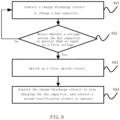
- control process of the uninterruptible power supply includes the following steps 1001 to 1007.
- step 1001 the relays K6 and K7 are switched on.
- the first rectification circuit is connected to the third capacitor C3.
- the AC outputted by the AC power supply is converted into DC by the diodes D1 to D6, and then limited by the current limiting resistors R1 and R2, to charge the third capacitor C3.
- step 1002 it is determined whether the voltage across the third capacitor C3 is greater than or equal to the set voltage. If the voltage across the third capacitor C3 is greater than or equal to the set voltage, the method proceeds to step 1003. Otherwise, the method returns to step 1001.
- step 1003 the charge-discharge circuit is controlled to boost the voltage across the third capacitor C3 and charge the bus capacitor.
- step 1004 it is determined whether the voltage across the bus capacitor is equal to the first voltage. If the voltage across the bus capacitor is equal to the first voltage, the method proceeds to step 1005. Otherwise, the method returns to step 1003.
- step 1005 the relays K1 to K3 are switched on.
- step 1006 the charge-discharge circuit is controlled to stop charging the bus capacitor, and the relay K6 and the relay K7 are switched off.
- Step 1007 the second rectification circuit is controlled to operate.
- control process of the uninterruptible power supply shown in FIG 10 is applicable to only the structure of the uninterruptible power supply shown in FIG 8 .
- control process of the uninterruptible power supply is adapted to the structure of the uninterruptible power supply, which is not listed herein.
- a computer-readable storage medium containing instructions, e.g., a memory containing instructions.
- the instructions when executed by the processor, perform the above method for controlling the uninterruptible power supply.
- the storage medium is a non-transitory computer readable storage medium.
- the non-transitory computer readable storage medium is a ROM, a random-access memory (RAM), a CD-ROM, a magnetic tape, a floppy disk, an optical data storage device, and the like.
- a computer program product is also provided.
- the computer program product includes a computer program.
- the computer program when executed by the processor, implements the method of controlling the uninterruptible power supply according to the present application.
- various aspects of the method of controlling the uninterruptible power supply according to the present application are also implemented in the form of a program product.
- the program product includes program code.
- the program code is configured to control the computer device to perform the steps in the method for controlling the uninterruptible power supply according to various exemplary embodiments of the present application described above in this specification.
- the program product may be in the form of any combination of one or more readable media.
- the readable medium is a readable signal medium or a readable storage medium.
- the readable storage medium is, for example, but not limited to, an electrical, magnetic, optical, electromagnetic, infrared, or semiconductor system, device, or apparatus, or any combination thereof. More specific examples (non-exhaustive list) of readable storage medium include: electrical connection with one or more conductors, a portable disk, a hard disk, a random access memory (RAM), read only memory (ROM), an erasable programmable read-only memory (EPROM or flash memory), an optical fiber, a portable compact disk read-only memory (CD-ROM), an optical storage device, a magnetic storage device, or any suitable combination of the above.
- the program product of the method for controlling the uninterruptible power supply of the embodiment of the present application adopts a portable compact disk read only memory (CD-ROM) and includes program codes, and is executable on an electronic device.
- CD-ROM portable compact disk read only memory
- the program product of the present application is not limited thereto.
- a readable storage medium is any tangible medium that contains or stores a program. The program is used by or in conjunction with an instruction execution system, apparatus or device.
- the readable signal medium includes a data signal that travels in baseband or as part of a carrier wave with readable program code carried therein. Such propagated data signals may be in many forms, including but not limited to electromagnetic signals, optical signals, or any suitable combination of the foregoing.
- the readable signal medium is also any readable medium other than a readable storage medium. The readable medium transmits, propagates or transports the program for use by or in connection with the instruction execution system, apparatus or device.
- the program code embodied on the readable medium may be transmitted using any appropriate medium, including but not limited to wireless, wireline, optical fiber cable, RF, etc., or any suitable combination of the foregoing.
- the program code for carrying out the operations of the present application is written in any combination of one or more programming languages.
- the programming language includes object-oriented programming languages such as Java, C++, etc., and also includes conventional procedural programming languages such as C language or similar programming languages.
- the program code may be executed on the user electronic device entirely, partially, as an independent software package, partly on the user electronic device and partly on a remote electronic device, or entirely on the remote electronic device or server.
- the remote electronic device is connected to the user electronic device through any kind of network, including a local area network (LAN) or a wide area network (WAN).
- the remote electronic device is connected to the external electronic device (e.g., via the Internet provided by an Internet service provider).
Landscapes
- Engineering & Computer Science (AREA)
- Power Engineering (AREA)
- Business, Economics & Management (AREA)
- Emergency Management (AREA)
- Stand-By Power Supply Arrangements (AREA)
Applications Claiming Priority (1)
| Application Number | Priority Date | Filing Date | Title |
|---|---|---|---|
| CN202310644269.2A CN119070457A (zh) | 2023-06-01 | 2023-06-01 | 一种不间断电源、及控制方法和供电系统 |
Publications (1)
| Publication Number | Publication Date |
|---|---|
| EP4472022A1 true EP4472022A1 (de) | 2024-12-04 |
Family
ID=98604465
Family Applications (1)
| Application Number | Title | Priority Date | Filing Date |
|---|---|---|---|
| EP23206569.8A Pending EP4472022A1 (de) | 2023-06-01 | 2023-10-30 | Unterbrechungsfreie stromversorgung, steuerverfahren und stromversorgungssystem |
Country Status (3)
| Country | Link |
|---|---|
| US (1) | US20240405597A1 (de) |
| EP (1) | EP4472022A1 (de) |
| CN (1) | CN119070457A (de) |
Citations (4)
| Publication number | Priority date | Publication date | Assignee | Title |
|---|---|---|---|---|
| US20050213357A1 (en) * | 2004-03-24 | 2005-09-29 | Esa Paatero | Power conversion apparatus with DC bus precharge circuits and methods of operation thereof |
| WO2015185630A1 (en) * | 2014-06-03 | 2015-12-10 | Abb Technology Ag | Uninterruptible power supply system with precharge converter |
| EP3806301A1 (de) * | 2019-10-09 | 2021-04-14 | ABB Schweiz AG | Wandleranordnung |
| US20220399746A1 (en) * | 2020-06-15 | 2022-12-15 | Toshiba Mitsubishi-Electric Industrial Systems Corporation | Power converter |
-
2023
- 2023-06-01 CN CN202310644269.2A patent/CN119070457A/zh active Pending
- 2023-10-30 EP EP23206569.8A patent/EP4472022A1/de active Pending
- 2023-11-22 US US18/518,209 patent/US20240405597A1/en active Pending
Patent Citations (4)
| Publication number | Priority date | Publication date | Assignee | Title |
|---|---|---|---|---|
| US20050213357A1 (en) * | 2004-03-24 | 2005-09-29 | Esa Paatero | Power conversion apparatus with DC bus precharge circuits and methods of operation thereof |
| WO2015185630A1 (en) * | 2014-06-03 | 2015-12-10 | Abb Technology Ag | Uninterruptible power supply system with precharge converter |
| EP3806301A1 (de) * | 2019-10-09 | 2021-04-14 | ABB Schweiz AG | Wandleranordnung |
| US20220399746A1 (en) * | 2020-06-15 | 2022-12-15 | Toshiba Mitsubishi-Electric Industrial Systems Corporation | Power converter |
Also Published As
| Publication number | Publication date |
|---|---|
| CN119070457A (zh) | 2024-12-03 |
| US20240405597A1 (en) | 2024-12-05 |
Similar Documents
| Publication | Publication Date | Title |
|---|---|---|
| US11299051B2 (en) | Electric charging system and method | |
| EP2846436B1 (de) | Schaltung für eine ununterbrochene stromversorgung | |
| US9124204B2 (en) | Inverter device | |
| EP3790155A1 (de) | Bordeigenes lade- und entladesystem | |
| US9979227B2 (en) | Line interactive UPS | |
| EP2815913A1 (de) | Ladeanordnung für elektrische Fahrzeuge | |
| US20170358926A1 (en) | Photovoltaic Air-conditioning System and Photovoltaic Air Conditioner Having Same | |
| EP3915826B1 (de) | Verfahren und system zum fahrzeug-zu-fahrzeug-laden von elektrofahrzeugen | |
| EP3916975A2 (de) | Umwandlungsvorrichtung | |
| CN113726137B (zh) | 变换装置 | |
| SG191259A1 (en) | Method and system for control power in remote dc power systems | |
| CN104218805A (zh) | 一种单双极性转换直流变换器 | |
| US20220181984A1 (en) | Isolated converter | |
| US9768617B2 (en) | Power management system comprising a power source, a source of renewable energy, and a power converter | |
| CN106452110A (zh) | 一种电力变换装置和微电网 | |
| CN111543001B (zh) | 具有ac正激电桥和改进的dc/dc拓扑的逆变器 | |
| JP7132720B2 (ja) | キュービクル | |
| EP3961847B1 (de) | Stromversorgungsvorrichtung | |
| CN114179643B (zh) | 一种双向充电桩 | |
| CN112054590B (zh) | 一种电容直流保障电源 | |
| EP4472022A1 (de) | Unterbrechungsfreie stromversorgung, steuerverfahren und stromversorgungssystem | |
| CN220291718U (zh) | 一种不间断电源和供电系统 | |
| Vinusha et al. | Improved power quality of single phase on-board charger with wide voltage conversion range | |
| CN220359041U (zh) | 一种辅助电源供电系统 | |
| CN117559829A (zh) | 功率变换器、供电系统及其软启动方法 |
Legal Events
| Date | Code | Title | Description |
|---|---|---|---|
| PUAI | Public reference made under article 153(3) epc to a published international application that has entered the european phase |
Free format text: ORIGINAL CODE: 0009012 |
|
| STAA | Information on the status of an ep patent application or granted ep patent |
Free format text: STATUS: THE APPLICATION HAS BEEN PUBLISHED |
|
| STAA | Information on the status of an ep patent application or granted ep patent |
Free format text: STATUS: REQUEST FOR EXAMINATION WAS MADE |
|
| AK | Designated contracting states |
Kind code of ref document: A1 Designated state(s): AL AT BE BG CH CY CZ DE DK EE ES FI FR GB GR HR HU IE IS IT LI LT LU LV MC ME MK MT NL NO PL PT RO RS SE SI SK SM TR |
|
| 17P | Request for examination filed |
Effective date: 20241126 |