EP4472018A1 - Systeme und verfahren zur kondensatorentladungssteuerung beim vorwärts- und rückwärtsladen - Google Patents
Systeme und verfahren zur kondensatorentladungssteuerung beim vorwärts- und rückwärtsladen Download PDFInfo
- Publication number
- EP4472018A1 EP4472018A1 EP24170870.0A EP24170870A EP4472018A1 EP 4472018 A1 EP4472018 A1 EP 4472018A1 EP 24170870 A EP24170870 A EP 24170870A EP 4472018 A1 EP4472018 A1 EP 4472018A1
- Authority
- EP
- European Patent Office
- Prior art keywords
- battery
- converter
- discharge
- bulk capacitor
- grid
- Prior art date
- Legal status (The legal status is an assumption and is not a legal conclusion. Google has not performed a legal analysis and makes no representation as to the accuracy of the status listed.)
- Pending
Links
Images


Classifications
-
- H—ELECTRICITY
- H02—GENERATION; CONVERSION OR DISTRIBUTION OF ELECTRIC POWER
- H02J—ELECTRIC POWER NETWORKS; CIRCUIT ARRANGEMENTS OR SYSTEMS FOR SUPPLYING OR DISTRIBUTING ELECTRIC POWER; SYSTEMS FOR STORING ELECTRIC ENERGY
- H02J7/00—Circuit arrangements for charging or discharging batteries or for supplying loads from batteries
- H02J7/02—Circuit arrangements for charging or discharging batteries or for supplying loads from batteries for charging batteries from AC mains by converters
- H02J7/04—Regulation of charging current or voltage
-
- H—ELECTRICITY
- H02—GENERATION; CONVERSION OR DISTRIBUTION OF ELECTRIC POWER
- H02J—ELECTRIC POWER NETWORKS; CIRCUIT ARRANGEMENTS OR SYSTEMS FOR SUPPLYING OR DISTRIBUTING ELECTRIC POWER; SYSTEMS FOR STORING ELECTRIC ENERGY
- H02J7/00—Circuit arrangements for charging or discharging batteries or for supplying loads from batteries
- H02J7/855—Circuit arrangements for charging or discharging batteries or for supplying loads from batteries with circuits adapted for supplying loads from the battery
-
- H—ELECTRICITY
- H02—GENERATION; CONVERSION OR DISTRIBUTION OF ELECTRIC POWER
- H02M—APPARATUS FOR CONVERSION BETWEEN AC AND AC, BETWEEN AC AND DC, OR BETWEEN DC AND DC, AND FOR USE WITH MAINS OR SIMILAR POWER SUPPLY SYSTEMS; CONVERSION OF DC OR AC INPUT POWER INTO SURGE OUTPUT POWER; CONTROL OR REGULATION THEREOF
- H02M1/00—Details of apparatus for conversion
- H02M1/32—Means for protecting converters other than automatic disconnection
- H02M1/322—Means for rapidly discharging a capacitor of the converter for protecting electrical components or for preventing electrical shock
-
- H—ELECTRICITY
- H02—GENERATION; CONVERSION OR DISTRIBUTION OF ELECTRIC POWER
- H02M—APPARATUS FOR CONVERSION BETWEEN AC AND AC, BETWEEN AC AND DC, OR BETWEEN DC AND DC, AND FOR USE WITH MAINS OR SIMILAR POWER SUPPLY SYSTEMS; CONVERSION OF DC OR AC INPUT POWER INTO SURGE OUTPUT POWER; CONTROL OR REGULATION THEREOF
- H02M3/00—Conversion of DC power input into DC power output
- H02M3/22—Conversion of DC power input into DC power output with intermediate conversion into AC
- H02M3/24—Conversion of DC power input into DC power output with intermediate conversion into AC by static converters
- H02M3/28—Conversion of DC power input into DC power output with intermediate conversion into AC by static converters using discharge tubes with control electrode or semiconductor devices with control electrode to produce the intermediate AC
- H02M3/325—Conversion of DC power input into DC power output with intermediate conversion into AC by static converters using discharge tubes with control electrode or semiconductor devices with control electrode to produce the intermediate AC using devices of a triode or a transistor type requiring continuous application of a control signal
- H02M3/335—Conversion of DC power input into DC power output with intermediate conversion into AC by static converters using discharge tubes with control electrode or semiconductor devices with control electrode to produce the intermediate AC using devices of a triode or a transistor type requiring continuous application of a control signal using semiconductor devices only
- H02M3/33569—Conversion of DC power input into DC power output with intermediate conversion into AC by static converters using discharge tubes with control electrode or semiconductor devices with control electrode to produce the intermediate AC using devices of a triode or a transistor type requiring continuous application of a control signal using semiconductor devices only having several active switching elements
- H02M3/33576—Conversion of DC power input into DC power output with intermediate conversion into AC by static converters using discharge tubes with control electrode or semiconductor devices with control electrode to produce the intermediate AC using devices of a triode or a transistor type requiring continuous application of a control signal using semiconductor devices only having several active switching elements having at least one active switching element at the secondary side of an isolation transformer
- H02M3/33584—Bidirectional converters
-
- H—ELECTRICITY
- H02—GENERATION; CONVERSION OR DISTRIBUTION OF ELECTRIC POWER
- H02M—APPARATUS FOR CONVERSION BETWEEN AC AND AC, BETWEEN AC AND DC, OR BETWEEN DC AND DC, AND FOR USE WITH MAINS OR SIMILAR POWER SUPPLY SYSTEMS; CONVERSION OF DC OR AC INPUT POWER INTO SURGE OUTPUT POWER; CONTROL OR REGULATION THEREOF
- H02M7/00—Conversion of AC power input into DC power output; Conversion of DC power input into AC power output
- H02M7/02—Conversion of AC power input into DC power output without possibility of reversal
- H02M7/04—Conversion of AC power input into DC power output without possibility of reversal by static converters
- H02M7/12—Conversion of AC power input into DC power output without possibility of reversal by static converters using discharge tubes with control electrode or semiconductor devices with control electrode
- H02M7/21—Conversion of AC power input into DC power output without possibility of reversal by static converters using discharge tubes with control electrode or semiconductor devices with control electrode using devices of a triode or transistor type requiring continuous application of a control signal
- H02M7/217—Conversion of AC power input into DC power output without possibility of reversal by static converters using discharge tubes with control electrode or semiconductor devices with control electrode using devices of a triode or transistor type requiring continuous application of a control signal using semiconductor devices only
-
- H—ELECTRICITY
- H02—GENERATION; CONVERSION OR DISTRIBUTION OF ELECTRIC POWER
- H02J—ELECTRIC POWER NETWORKS; CIRCUIT ARRANGEMENTS OR SYSTEMS FOR SUPPLYING OR DISTRIBUTING ELECTRIC POWER; SYSTEMS FOR STORING ELECTRIC ENERGY
- H02J2105/00—Networks for supplying or distributing electric power characterised by their spatial reach or by the load
- H02J2105/30—Networks for supplying or distributing electric power characterised by their spatial reach or by the load the load networks being external to vehicles, i.e. exchanging power with vehicles
- H02J2105/33—Networks for supplying or distributing electric power characterised by their spatial reach or by the load the load networks being external to vehicles, i.e. exchanging power with vehicles exchanging power with road vehicles
- H02J2105/37—Networks for supplying or distributing electric power characterised by their spatial reach or by the load the load networks being external to vehicles, i.e. exchanging power with vehicles exchanging power with road vehicles exchanging power with electric vehicles [EV] or with hybrid electric vehicles [HEV]
-
- H—ELECTRICITY
- H02—GENERATION; CONVERSION OR DISTRIBUTION OF ELECTRIC POWER
- H02J—ELECTRIC POWER NETWORKS; CIRCUIT ARRANGEMENTS OR SYSTEMS FOR SUPPLYING OR DISTRIBUTING ELECTRIC POWER; SYSTEMS FOR STORING ELECTRIC ENERGY
- H02J2207/00—Details of circuit arrangements for charging or discharging batteries or supplying loads from batteries
- H02J2207/20—Charging or discharging characterised by the power electronics converter
-
- H—ELECTRICITY
- H02—GENERATION; CONVERSION OR DISTRIBUTION OF ELECTRIC POWER
- H02M—APPARATUS FOR CONVERSION BETWEEN AC AND AC, BETWEEN AC AND DC, OR BETWEEN DC AND DC, AND FOR USE WITH MAINS OR SIMILAR POWER SUPPLY SYSTEMS; CONVERSION OF DC OR AC INPUT POWER INTO SURGE OUTPUT POWER; CONTROL OR REGULATION THEREOF
- H02M1/00—Details of apparatus for conversion
- H02M1/0067—Converter structures employing plural converter units, other than for parallel operation of the units on a single load
- H02M1/007—Plural converter units in cascade
-
- H—ELECTRICITY
- H02—GENERATION; CONVERSION OR DISTRIBUTION OF ELECTRIC POWER
- H02M—APPARATUS FOR CONVERSION BETWEEN AC AND AC, BETWEEN AC AND DC, OR BETWEEN DC AND DC, AND FOR USE WITH MAINS OR SIMILAR POWER SUPPLY SYSTEMS; CONVERSION OF DC OR AC INPUT POWER INTO SURGE OUTPUT POWER; CONTROL OR REGULATION THEREOF
- H02M1/00—Details of apparatus for conversion
- H02M1/42—Circuits or arrangements for compensating for or adjusting power factor in converters or inverters
- H02M1/4208—Arrangements for improving power factor of AC input
- H02M1/4233—Arrangements for improving power factor of AC input using a bridge converter comprising active switches
-
- H—ELECTRICITY
- H02—GENERATION; CONVERSION OR DISTRIBUTION OF ELECTRIC POWER
- H02M—APPARATUS FOR CONVERSION BETWEEN AC AND AC, BETWEEN AC AND DC, OR BETWEEN DC AND DC, AND FOR USE WITH MAINS OR SIMILAR POWER SUPPLY SYSTEMS; CONVERSION OF DC OR AC INPUT POWER INTO SURGE OUTPUT POWER; CONTROL OR REGULATION THEREOF
- H02M3/00—Conversion of DC power input into DC power output
- H02M3/01—Resonant DC/DC converters
-
- H—ELECTRICITY
- H02—GENERATION; CONVERSION OR DISTRIBUTION OF ELECTRIC POWER
- H02M—APPARATUS FOR CONVERSION BETWEEN AC AND AC, BETWEEN AC AND DC, OR BETWEEN DC AND DC, AND FOR USE WITH MAINS OR SIMILAR POWER SUPPLY SYSTEMS; CONVERSION OF DC OR AC INPUT POWER INTO SURGE OUTPUT POWER; CONTROL OR REGULATION THEREOF
- H02M3/00—Conversion of DC power input into DC power output
- H02M3/22—Conversion of DC power input into DC power output with intermediate conversion into AC
- H02M3/24—Conversion of DC power input into DC power output with intermediate conversion into AC by static converters
- H02M3/28—Conversion of DC power input into DC power output with intermediate conversion into AC by static converters using discharge tubes with control electrode or semiconductor devices with control electrode to produce the intermediate AC
- H02M3/325—Conversion of DC power input into DC power output with intermediate conversion into AC by static converters using discharge tubes with control electrode or semiconductor devices with control electrode to produce the intermediate AC using devices of a triode or a transistor type requiring continuous application of a control signal
- H02M3/335—Conversion of DC power input into DC power output with intermediate conversion into AC by static converters using discharge tubes with control electrode or semiconductor devices with control electrode to produce the intermediate AC using devices of a triode or a transistor type requiring continuous application of a control signal using semiconductor devices only
- H02M3/33569—Conversion of DC power input into DC power output with intermediate conversion into AC by static converters using discharge tubes with control electrode or semiconductor devices with control electrode to produce the intermediate AC using devices of a triode or a transistor type requiring continuous application of a control signal using semiconductor devices only having several active switching elements
- H02M3/33573—Full-bridge at primary side of an isolation transformer
-
- Y—GENERAL TAGGING OF NEW TECHNOLOGICAL DEVELOPMENTS; GENERAL TAGGING OF CROSS-SECTIONAL TECHNOLOGIES SPANNING OVER SEVERAL SECTIONS OF THE IPC; TECHNICAL SUBJECTS COVERED BY FORMER USPC CROSS-REFERENCE ART COLLECTIONS [XRACs] AND DIGESTS
- Y02—TECHNOLOGIES OR APPLICATIONS FOR MITIGATION OR ADAPTATION AGAINST CLIMATE CHANGE
- Y02T—CLIMATE CHANGE MITIGATION TECHNOLOGIES RELATED TO TRANSPORTATION
- Y02T10/00—Road transport of goods or passengers
- Y02T10/60—Other road transportation technologies with climate change mitigation effect
- Y02T10/70—Energy storage systems for electromobility, e.g. batteries
Definitions
- Various embodiments of the present disclosure relate generally to systems and methods for capacitor discharge and, more particularly, to systems and methods for capacitor discharge and energy storage in a bidirectional on-board charger.
- An on-board charger may be a bi-directional system that converts AC voltage to DC voltage in a charging mode (grid-to-battery) and DC voltage to AC voltage in a discharge or inverter mode (battery-to-grid).
- a bi-directional on-board charger for automotive applications, in case of loss of communication or critical faults in a vehicle, components in the on-board charger should be discharged below a HV safety value.
- Some systems may not meet increased efficiency requirements and/or higher power density of an on-board charger.
- the present disclosure is directed to overcoming one or more of these above-referenced challenges.
- the techniques described herein relate to a system including: an alternating current (AC) to direct current (DC) converter (AC-DC converter) including: a bulk capacitor, and an AC-DC converter switch connectable to a line voltage; a DC to DC converter (DC-DC converter) connected to the AC-DC converter, the DC-DC converter including: one or more transformers having a secondary side connectable to a battery, and a bridge driver connected to a primary side of the one or more transformers, the bridge driver including a bridge driver switch; and one or more controllers configured to control an operation of the bridge driver switch to control a discharge of the bulk capacitor to the battery at an end of a grid-to-battery operation, the grid-to-battery operation to supply electric power from the line voltage to the battery.
- AC-DC converter alternating current to direct current (DC) converter
- DC-DC converter DC to DC converter
- DC-DC converter DC to DC converter
- the DC-DC converter including: one or more transformers having a secondary side connectable to a battery, and
- the techniques described herein relate to a system, wherein the one or more controllers are further configured to control an operation of: the bridge driver switch to control a discharge of the bulk capacitor to the battery in one or more of the grid-to-battery operation or a battery-to-grid operation, the battery-to-grid operation to supply electric power from the battery to a load of the line voltage, and the AC-DC converter switch to control the discharge of the bulk capacitor to the load of the line voltage in the battery-to-grid operation.
- the techniques described herein relate to a system, wherein the one or more controllers are further configured to control the discharge of the bulk capacitor to the battery at the end of a grid-to-battery operation based on: the battery being connected to the DC-DC converter, and no hardware-related faults in the AC-DC converter or the DC-DC converter.
- the techniques described herein relate to a system, wherein the one or more controllers are further configured to control the discharge of the bulk capacitor to the battery while a voltage of the bulk capacitor is above a peak voltage of the line voltage plus a hysteresis factor, when the line voltage is connected to the AC-DC converter.
- the techniques described herein relate to a system, wherein the one or more controllers are further configured to control the discharge of the bulk capacitor to the battery while a voltage of the bulk capacitor is above a threshold, when the line voltage is disconnected from the AC-DC converter.
- the techniques described herein relate to a system, wherein the threshold is 60V.
- the techniques described herein relate to a system, wherein the one or more controllers are further configured to control the discharge of the bulk capacitor to the battery based on a current threshold.
- the techniques described herein relate to a system, wherein the one or more controllers are further configured to modify the current threshold based on a change in a connection to one or more of the line voltage or the battery.
- the techniques described herein relate to a system, wherein the line voltage is a three phase line voltage.
- the techniques described herein relate to a system, wherein the DC-DC converter further includes: a bridge rectifier connected to a secondary side of the one or more transformers, the bridge rectifier including a bridge rectifier switch.
- the techniques described herein relate to a system, wherein the one or more controllers are configured to control an operation of the bridge driver switch to control a discharge of the bulk capacitor without using a discharge resistor in the AC-DC converter or the DC-DC converter.
- the techniques described herein relate to a system, further including: the battery connected to the DC-DC converter, wherein the system is provided as a bidirectional battery charger configured to: receive input AC power from the line voltage through the AC-DC converter, convert the AC power to DC power, and supply the DC power to the battery to charge the battery in the grid-to-battery operation, and receive DC power from the battery through the DC-DC converter, convert the DC power to AC power, and supply the AC power to the load of the line voltage as output AC power in the battery-to-grid operation.
- the system is provided as a bidirectional battery charger configured to: receive input AC power from the line voltage through the AC-DC converter, convert the AC power to DC power, and supply the DC power to the battery to charge the battery in the grid-to-battery operation, and receive DC power from the battery through the DC-DC converter, convert the DC power to AC power, and supply the AC power to the load of the line voltage as output AC power in the battery-to-grid operation.
- the techniques described herein relate to a system, further including: an electric vehicle including the battery connected to the DC-DC converter.
- the techniques described herein relate to a system, further including: an electric vehicle including the battery connected to the DC-DC converter, wherein the battery-to-grid operation is operable to supply electric power from the battery to an AC outlet of the electric vehicle as the load of the line voltage.
- the techniques described herein relate to a method for controlling a system including an alternating current (AC) to direct current (DC) converter including: a bulk capacitor, and an AC to DC converter switch connectable to a line voltage; and a DC to DC converter connected to the AC to DC converter, the DC to DC converter including: one or more transformers having a secondary side connectable to a battery, and a bridge driver connected to a primary side of the one or more transformers, the bridge driver including a bridge driver switch, the method including: performing, by one or more controllers, operations including: controlling an operation of the bridge driver switch to control a discharge of the bulk capacitor to the battery at an end of a grid-to-battery operation, the grid-to-battery operation to supply electric power from the line voltage to the battery.
- AC alternating current
- DC direct current
- the techniques described herein relate to a method, wherein the operations further include: controlling an operation of the bridge driver switch to control a discharge of the bulk capacitor to the battery in one or more of the grid-to-battery operation or a battery-to-grid operation, the battery-to-grid operation to supply electric power from the battery to a load of the line voltage, and controlling an operation of the AC to DC converter switch to control the discharge of the bulk capacitor to a load of the line voltage in the battery-to-grid operation.
- the techniques described herein relate to a method, wherein the operations further include: controlling the discharge of the bulk capacitor to the battery at the end of a grid-to-battery operation based on: the battery being connected to the DC to DC converter, and no hardware-related faults in the AC to DC converter or the DC to DC converter.
- the techniques described herein relate to a method, wherein the operations further include: controlling the discharge of the bulk capacitor to the battery while a voltage of the bulk capacitor is above a peak voltage of the line voltage plus a hysteresis factor, when the line voltage is connected to the AC to DC converter, and controlling the discharge of the bulk capacitor to the battery while the voltage of the bulk capacitor is above a threshold, when the line voltage is disconnected from the AC to DC converter.
- the techniques described herein relate to a method, wherein the operations further include: controlling the discharge of the bulk capacitor to the battery based on a current threshold, and modifying the current threshold based on a change in a connection to one or more of the line voltage or the battery.
- the techniques described herein relate to a system including: one or more controllers configured to control an operation of a bridge driver switch to control a discharge of a bulk capacitor to a battery at an end of a grid-to-battery operation, the grid-to-battery operation to supply electric power from a line voltage to the battery.
- the techniques described herein relate to a system including: an alternating current (AC) to direct current (DC) converter (AC-DC converter) including a bulk capacitor, the AC-DC converter connectable to a line voltage; a DC to DC converter (DC-DC converter) connected to the AC-DC converter, the DC-DC converter including: one or more transformers having a secondary side connectable to a battery, a bridge rectifier connected to the secondary side of the one or more transformers, the bridge rectifier including a bridge rectifier switch, and a filter capacitor; and one or more controllers configured to control an operation of the bridge rectifier switch to control a discharge of the filter capacitor to the bulk capacitor.
- AC alternating current
- DC-DC converter direct current converter
- DC-DC converter DC to DC converter
- the techniques described herein relate to a system, wherein the one or more controllers are further configured to control the operation of the bridge rectifier switch to control the discharge of the filter capacitor to the bulk capacitor in each of a grid-to-battery operation and a battery-to-grid operation, the grid-to-battery operation to supply electric power from the line voltage to the battery and the battery-to-grid operation to supply electric power from the battery to a load of the line voltage.
- the techniques described herein relate to a system, wherein the one or more controllers are further configured to: determine whether the battery is connected to the DC-DC converter, and control the operation of the bridge rectifier switch to control the discharge of the filter capacitor to the bulk capacitor, when the battery is determined to be disconnected from the DC-DC converter.
- the techniques described herein relate to a system, wherein the one or more controllers are further configured to: set a battery disconnect fault and end one or more of the grid-to-battery operation or the battery-to-grid operation, when the battery is determined to be disconnected from the DC-DC converter.
- the techniques described herein relate to a system, wherein the one or more controllers are further configured to: determine a current threshold, and control the operation of the bridge rectifier switch to control the discharge of the filter capacitor to the bulk capacitor, when the one or more of the grid-to-battery operation or the battery-to-grid operation has ended.
- the techniques described herein relate to a system, wherein the filter capacitor is configured to filter a high frequency ripple from electric power supplied to the battery.
- the techniques described herein relate to a system, wherein the one or more controllers are further configured to control the discharge of the filter capacitor to the bulk capacitor while a voltage of the filter capacitor is above a threshold.
- the techniques described herein relate to a system, wherein the threshold is 60V.
- the techniques described herein relate to a system, wherein the one or more controllers are configured to control the discharge of the filter capacitor to the bulk capacitor to transfer electrical energy from terminals that are exposed when the battery is disconnected from the DC-DC converter to the bulk capacitor, wherein the bulk capacitor is less exposed to external sources than the filter capacitor.
- the techniques described herein relate to a system, wherein the discharge of the filter capacitor to the bulk capacitor decreases a voltage of the filter capacitor more than an increase in voltage of the bulk capacitor.
- the techniques described herein relate to a system, wherein the one or more controllers are further configured to control a discharge of the bulk capacitor after controlling the discharge of the filter capacitor to the bulk capacitor.
- the techniques described herein relate to a system, further including: the battery connected to the DC-DC converter, wherein the system is provided as a bidirectional battery charger configured to: receive input AC power from the line voltage through the AC-DC converter, convert the AC power to DC power, and supply the DC power to the battery to charge the battery in the grid-to-battery operation, and receive DC power from the battery through the DC-DC converter, convert the DC power to AC power, and supply the AC power to the load of the line voltage as output AC power in the battery-to-grid operation.
- the system is provided as a bidirectional battery charger configured to: receive input AC power from the line voltage through the AC-DC converter, convert the AC power to DC power, and supply the DC power to the battery to charge the battery in the grid-to-battery operation, and receive DC power from the battery through the DC-DC converter, convert the DC power to AC power, and supply the AC power to the load of the line voltage as output AC power in the battery-to-grid operation.
- the techniques described herein relate to a system, further including: an electric vehicle including the battery connected to the DC-DC converter.
- the techniques described herein relate to a system, further including: an electric vehicle including the battery connected to the DC-DC converter, wherein the battery-to-grid operation is operable to supply electric power from the battery to an AC outlet of the electric vehicle as the load of the line voltage.
- the techniques described herein relate to a method for controlling a system including an alternating current (AC) to direct current (DC) converter including a bulk capacitor, the AC to DC converter connectable to a line voltage; and a DC to DC converter connected to the AC to DC converter, the DC to DC converter including: one or more transformers having a secondary side connectable to a battery, a bridge rectifier connected to the secondary side of the one or more transformers, the bridge rectifier including a bridge rectifier switch, and a filter capacitor, the method including: performing, by one or more controllers, operations including: controlling an operation of the bridge rectifier switch to control a discharge of the filter capacitor to the bulk capacitor.
- AC alternating current
- DC direct current
- the techniques described herein relate to a method, wherein the operations further include: controlling the operation of the bridge rectifier switch to control the discharge of the filter capacitor to the bulk capacitor in each of a grid-to-battery operation and a battery-to-grid operation, the grid-to-battery operation to supply electric power from the line voltage to the battery and the battery-to-grid operation to supply electric power from the battery to a load of the line voltage.
- the techniques described herein relate to a method, wherein the operations further include: determining whether the battery is connected to the DC to DC converter, and controlling the operation of the bridge rectifier switch to control the discharge of the filter capacitor to the bulk capacitor, when the battery is determined to be disconnected from the DC to DC converter.
- the techniques described herein relate to a method, wherein the operations further include: setting a battery disconnect fault and ending one or more of the grid-to-battery operation or the battery-to-grid operation, when the battery is determined to be disconnected from the DC to DC converter.
- the techniques described herein relate to a method, wherein the operations further include: determining a current threshold, and controlling the operation of the bridge rectifier switch to control the discharge of the filter capacitor to the bulk capacitor, when the one or more of the grid-to-battery operation or the battery-to-grid operation has ended.
- the techniques described herein relate to a system including: one or more controllers configured to control an operation of a bridge rectifier switch to control a discharge of a filter capacitor to a bulk capacitor.
- Various embodiments of the present disclosure relate generally to systems and methods for capacitor discharge and, more particularly, to systems and methods for capacitor discharge and energy storage in a bidirectional on-board charger.
- a charger may operate with a single-phase or three-phase AC power source.
- the charger may be designed to support a wide range of HV battery voltage ranges, for example, 400V and 800V systems and maximum output power of 11 kilowatts and 22 kilowatts.
- a DC-DC Converter with an LLC resonant structure may be used.
- a PFC converter with a single-phase or three-phase power supply may be employed.
- a battery charger according to the disclosure may operate with multiple types of AC input power supplies, including single phase, split/dual/two phase, and three-phase power supplies.
- the charger may be compatible with a wide range of configuration.
- An Inductor-Inductor-Capacitor (LLC) converter may be used as a second stage converter using a DC link voltage generated from the PFC as the input voltage for the converter.
- LLC Inductor-Inductor-Capacitor
- the disclosure is not limited thereto.
- a battery charger according to the disclosure may include a two-stage configuration, including an AC-DC power factor correction converter stage and an isolated DC-DC converter stage.
- the isolated DC-DC converter may include a full-bridge driver configuration with resonant tank elements to achieve better efficiency.
- the DC-DC converter may be designed to charge the battery from minimum voltage to maximum voltage.
- a battery charger may operate as a battery charger only, or operate bidirectionally for a charging operation or a power supply operation.
- the converter may either receive power from an AC power source and provide DC power to a battery, or receive power from the battery and provide power as an AC power source.
- a vehicle to grid (V2G) configuration may be achieved with a designed control strategy for single-phase, two-phase, and three-phase systems.
- Switches of the battery charger may be any devices, such as GTO, thyristors, or MOSFETs/ IGBTs with series diodes, for example. These switches may also be mechanical components (such as relays or contactors) if sufficient failure rates and arcing conditions during operation are met. Additionally, if the switches are semi-permanent in position, the switches may be implemented as one or more jumper connectors or dual in-line package (DIP) switches.
- DIP dual in-line package
- Electric vehicles, energy storage systems, and backup generators convert electric power from one form to another.
- an on-board charger for a vehicle may have a dual purpose.
- the on-board charger may be a bi-directional system that converts AC voltage to DC voltage in a charging mode (grid-to-battery) and DC voltage to AC voltage in a discharge or inverter mode (battery-to-grid).
- the charging mode may convert the grid AC into DC voltage to charge the vehicle high voltage (HV) battery, and the discharge or inverter mode may convert the HV battery DC voltage into AC voltage that may be supplied to grid line voltage, be supplied as a backup generator to power a house when the grid is down, or as an inverter to supply voltage to vehicle AC outlets, for example.
- the on-board charger may have a two-stage design to meet automotive requirements, with an AC-DC power factor converter in a first stage and an isolated DC-DC converter in a second stage.
- the AC-DC power factor converter in the first stage may convert input power from an AC grid system to a required DC bulk capacitor voltage while ensuring the AC current is within limits and the power factor is close to unity.
- the bulk capacitor may be de-energized completely, so the AC-DC power factor converter may pre-charge the bulk capacitor to avoid inrush current scenarios.
- the AC-DC power factor converter may operate in a fixed switching frequency and variable duty cycle mode to regulate the bulk capacitor voltage at a desired voltage setpoint and maintain unity power factor.
- Systems to pre-charge the bulk capacitor and limit the inrush AC current may include a positive temperature coefficient resistor, or a normal resistor, with an appropriate continuous power rating in conjunction with a high voltage relay.
- the power factor converter operating as an inverter, may use the bulk capacitor voltage to convert DC battery voltage into a desired AC output.
- the AC output may vary in voltage, frequency, and/or phase type.
- the power factor converter may operate in different modes to generate the AC voltage depending on the phase type required.
- the isolated DC-DC converter in the second stage may use the bulk capacitor voltage to convert AC voltage to charge the HV battery at a commanded current.
- the isolated DC-DC converter may be used to maintain the HV battery voltage.
- a resonant isolated DC-DC converter may operate with a variable switching frequency and a fixed duty cycle to regulate the HV secondary current to the desired setpoint to charge the HV battery.
- the switching frequency may be maintained close to the resonant frequency of the converter for a more efficient operation.
- the LC resonant tank network may control the resonant frequency, and the frequency range along with the transformer turn ratio may determine the DC output of the isolated DC-DC converter.
- the isolated DC-DC converter may use the battery voltage to charge the bulk capacitor.
- the resonant isolated DC-DC converter may operate in variable or fixed frequency, and variable or fixed duty cycle modes, to ensure the bulk capacitor voltage is maintained within limits at all operating conditions from no AC load to a full AC load.
- the bulk capacitor in a bi-directional on-board charger for automotive applications may be in the range of millifarads.
- the bulk capacitor may be one or more electrolytic capacitors with higher capacitance density.
- a rated capacitor voltage may differ for 400V and 800V applications, for example.
- a series parallel combination may be used to achieve a higher rated voltage.
- a voltage bulk capacitor HV bus, HV- to HV+, in an 800V system may vary from 360VDC to 850VDC.
- the bulk capacitor may maintain a stable link voltage during charging and inverter mode operation of the on-board charger.
- the isolated DC-DC converter stage may require stable input DC voltage during battery charging operation, and the PFC converter stage, operating as an inverter, may require a stable input DC voltage during inverter mode operation.
- the HV bus in the system should be discharged below the HV safety value of 60V.
- the bulk capacitor may be internal to the on-board charger, and less externally accessible as the HV battery bus, so the requirements to discharge the bulk capacitor may be comparatively less stringent relative to the requirements to discharge HV battery bus capacitance and AC bus capacitance.
- On-board chargers may have two types of discharge mechanisms, where the two types are passive and active.
- Passive discharge uses a resistive element, such as a resistor, for example, to discharge the voltage across the bulk capacitor by heat dissipation on the resistive element.
- the resistance value may be high to minimize the continuous power dissipation, which may result in a long discharge time in the order of minutes to tens of minutes.
- Active discharge may switch a connection of the resistive element with the bulk capacitor by turning on and off an active device, such as a MOSFET or IGBT, for example. Because the power dissipation is not continuous, a lower resistance value may be used for active discharge relative to passive discharge. Additionally, a much faster discharge rate may be achieved, such as in the order of a few seconds, for example.
- One or more embodiments may provide a method to discharge the bulk capacitor based on the operating mode of a bi-directional on-board charger. Adding active and/or low resistance passive discharge may not meet increased efficiency requirements and/or higher power density of the on-board charger. One or more embodiments does not require additional hardware for an on-board charger. One or more embodiments may provide a controlled current scheme to discharge the bulk capacitor energy to the HV battery load or AC output load. The controlled current scheme may discharge energy even without a load to the output capacitors, but may be delayed to maintain the output capacitor voltages within limits.
- One or more embodiments may provide an on-board charger with charging mode discharge conditions for a bulk capacitor, where the charging mode discharge conditions include one or more of: (1) the HV battery is connected to the on-board charger, (2) a critical hardware-related fault is not present in either the AC-DC power factor converter or the isolated DC-DC converter, (3) an on-board charger command is a standby operation, or (4) an AC voltage may be lost if a charging plug is removed in the middle of a charging event.
- One or more embodiments may determine that all the charging mode discharge conditions are met, then begin the discharge operation of the bulk capacitor. When an input AC voltage is present, then the discharge process will continue until the bulk capacitor voltage is equal to a peak voltage of the input AC voltage plus a predetermined hysteresis.
- the predetermined hysteresis may be 10V, for example. If the AC grid voltage is disconnected from the bulk capacitor, the discharge process will continue until the bulk capacitor voltage is below a threshold, such as 60V, for example.
- the isolated DC-DC converter may be operational and the AC-DC power factor converter may be non-operational. In a non-operational state, all switches may be open, for example.
- the isolated DC-DC converter may discharge the bulk capacitor energy into the HV battery with a predetermined current reference. If the HV battery is not connected, the current reference may be modified to ensure the HVDC output capacitor voltage is within limits.
- a predetermined current reference may be a reference up to 40A, and a modified current reference may be 0.5A to avoid overcharging output capacitors.
- One or more embodiments may provide an on-board charger with inverter mode discharge conditions for a bulk capacitor, where the inverter mode discharge conditions include one or more of: (1) a critical hardware-related fault is not present in either the AC-DC power factor converter or the isolated DC-DC converter, or (2) an on-board charger command is a standby operation.
- One or more embodiments may determine that all the inverter mode discharge conditions are met, then begin the discharge operation of the bulk capacitor.
- the isolated DC-DC converter may be non-operational and the power factor converter may be operational.
- the power factor converter may discharge the bulk capacitor energy to the AC output load with a predetermined current reference. If the AC output load is disconnected, the current reference may be modified to ensure the AC output capacitor voltage is within limits.
- One or more embodiments may discharge the bulk capacitor voltage to below a threshold, such as 60V, for example.
- One or more embodiments may provide a discharge of high voltage bus capacitance.
- the HV bus capacitance may include the output capacitance of the isolated DC-DC converter.
- the output capacitance may be a high voltage filter capacitor that filters high frequency ripple to the HV battery.
- the high voltage filter capacitor may be in the range of microfarads for on-board charger applications.
- the HV bus capacitance may be discharged into the bulk capacitor in a controlled manner.
- One or more embodiments may control the discharge of the HV filter capacitor to the bulk capacitor to transfer electrical energy from terminals that are exposed when the battery is disconnected from the HVDC to the bulk capacitor, wherein the bulk capacitor is less exposed to external sources than the HV filter capacitor.
- both the power factor converter and the isolated DC-DC converter may enter a fault mode and stop power conversion.
- the isolated DC-DC converter may set a predetermined current reference and begin discharging the HV bus capacitance into the bulk capacitor.
- the secondary side (HV battery) switch(es) may be operated to discharge the HV bus capacitance into the bulk capacitor.
- the primary side (bulk capacitor) switch(es) may be turned off so that the body diodes of the switch(es) create a path for the discharge.
- a discharge from the HV bus to bulk capacitor may increase the bulk capacitor voltage by only a few volts. For example, if the HV bus capacitor, which may be less than approximately 20 ⁇ F, is charged to 900V and the HV battery is disconnected, then the discharge to the bulk capacitor, which may be approximately 1mF, and charged to approximately 800V may begin. Considering an energy transfer from HV bus capacitor to the bulk capacitor until the HV bus capacitor voltage falls below 60V, the bulk capacitor voltage would only increase from 800V to 810V, which is a 10V increase.
- One or more embodiments may provide a bi-directional on-board charger with a system to discharge a bulk capacitor and HV bus capacitor, without using additional hardware components.
- One or more embodiments may provide a current-controlled method to discharge the capacitors to improve capacitor life and reduce the deterioration of the circuit components.
- One or more embodiments may provide a system able to handle high current so that discharge speed may be increased.
- One or more embodiments may provide a system to discharge the bulk capacitor into the HV battery load during a forward charging (grid-to-battery) operation and into the AC load during a reverse charging (battery-to-grid) operation.
- One or more embodiments may use current limits so that the HV bus capacitor and AC output capacitor voltages are within limits.
- One or more embodiments may discharge the HV bus capacitor into the bulk capacitor upon disconnection from the HV battery.
- Some designs for capacitor discharge use passive discharge methods or active discharge methods. Passive discharge uses a continuously connected resistor, which reduces efficiency and thermal performance. Active discharge requires hardware updates, such as additional FETs, power supplies, and controllers, for example, and a thermal handling capability of the active discharge resistor must be considered for multiple discharge attempts.
- One or more embodiments may provide a system that uses the HV DC-DC stage to discharge the bulk capacitor into the HV battery load during a forward charging (grid-to-battery) operation.
- One or more embodiments may control a current of the discharge using a current loop, without additional hardware.
- One or more embodiments may provide a system that, if the HV battery load is disconnected, uses a combination of the current and voltage loop to discharge the bulk capacitor while ensuring the HV bus capacitor voltage is within limits.
- One or more embodiments may provide a system that uses the PFC stage to discharge the bulk capacitor into the AC load during a reverse charging (battery-to-grid) operation.
- One or more embodiments may control a current of the discharge using a current loop, without additional hardware.
- One or more embodiments may provide a system that, if the AC load is disconnected, uses a combination of the current and voltage loop to discharge the bulk capacitor while ensuring the AC bus capacitor voltage is within limits.
- One or more embodiments may provide a system that, if the HV bus gets disconnected from the HV battery, discharges the energy stored in the HV bus into the bulk capacitor by operating the HV DC-DC converter in reverse mode.
- One or more embodiments may set an appropriate current reference to control the rate of the discharge.
- One or more embodiments may provide a system that transfers energy from the HV bus capacitor to the bulk capacitor with a very small increase in bulk capacitor voltage.
- FIG. 1 depicts an exemplary system infrastructure for a battery charger, according to one or more embodiments.
- a battery charger 100 may include or be electrically connectable to a charging connector 110.
- the charging connector 110 may provide an electrical connection from an external power supply to the battery charger 100, and may be a Type 1 or a Type 2 connector, for example.
- the charging connector 110 may transfer single phase, two-phase, or three phase power.
- the battery charger 100 may include a Power Factor Correction (PFC) converter 120, an HV DC-DC converter (HVDC) 130, and a controller 300 receiving signals from input sensor 150.
- Power Factor Correction (PFC) converter 120 may be an AC-DC converter.
- HV DC-DC converter (HVDC) 130 may be a DC-DC converter.
- Controller 300 may include one or more controllers.
- the battery charger 100 may include or be electrically connectable to an HV battery 140.
- the battery charger 100 may be used in automotive vehicles as an onboard charger to transfer power from an external power source through charging connector 110 to HV battery 140 in a grid-to-battery operation, or to transfer power from HV battery 140 in a vehicle to grid configuration (a battery-to-grid operation).
- the battery charger 100 may be included in a system provided as an electric vehicle including a motor configured to rotate based on power received from the HV battery 140.
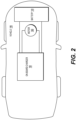
- FIG. 2 depicts an exemplary system infrastructure for a vehicle including a battery charger, according to one or more embodiments.
- the battery charger 100 may be a combined inverter and converter.
- electric vehicle 185 may include battery charger 100, motor 190, and battery 140.
- Battery charger 100 may include components to receive electrical power from an external source and output electrical power to charge battery 140 of electric vehicle 185.
- Battery charger 100 may convert DC power from battery 140 in electric vehicle 185 to AC power, to drive motor 190 of the electric vehicle 185, for example, but the embodiments are not limited thereto.
- battery charger 100 may include components to receive electrical power from an external source and output electrical power to charge battery 140 without motor 190 connected to battery charger 100.
- Battery charger 100 may be bidirectional, and may convert DC power to AC power, or convert AC power to DC power, such as during regenerative braking, for example.
- Battery charger 100 may be a three-phase inverter, a single-phase inverter, or a multi-phase inverter.
- FIG. 3 depicts an implementation of a controller 300 that may execute techniques presented herein, according to one or more embodiments.
- FIG. 3 and the following discussion provide a brief, general description of a suitable computing environment in which the present disclosure may be implemented.
- any of the disclosed systems, methods, and/or graphical user interfaces may be executed by or implemented by a computing system consistent with or similar to that depicted in FIG. 3 .
- aspects of the present disclosure are described in the context of computer-executable instructions, such as routines executed by a data processing device, e.g., a server computer, wireless device, and/or personal computer.
- aspects of the present disclosure may be embodied in a special purpose computer and/or data processor that is specifically programmed, configured, and/or constructed to perform one or more of the computer-executable instructions explained in detail herein. While aspects of the present disclosure, such as certain functions, are described as being performed exclusively on a single device, the present disclosure may also be practiced in distributed environments where functions or modules are shared among disparate processing devices, which are linked through a communications network, such as a Local Area Network ("LAN”), Wide Area Network (“WAN”), and/or the Internet. Similarly, techniques presented herein as involving multiple devices may be implemented in a single device. In a distributed computing environment, program modules may be located in both local and/or remote memory storage devices.
- LAN Local Area Network
- WAN Wide Area Network
- aspects of the present disclosure may be stored and/or distributed on non-transitory computer-readable media, including magnetically or optically readable computer discs, hard-wired or preprogrammed chips (e.g., EEPROM semiconductor chips), nanotechnology memory, biological memory, or other data storage media.
- computer implemented instructions, data structures, screen displays, and other data under aspects of the present disclosure may be distributed over the Internet and/or over other networks (including wireless networks), on a propagated signal on a propagation medium (e.g., an electromagnetic wave(s), a sound wave, etc.) over a period of time, and/or they may be provided on any analog or digital network (packet switched, circuit switched, or other scheme).
- the controller 300 may include a set of instructions that can be executed to cause the controller 300 to perform any one or more of the methods or computer-based functions disclosed herein.
- the controller 300 may operate as a standalone device or may be connected, e.g., using a network, to other computer systems or peripheral devices.
- the controller 300 may operate in the capacity of a server or as a client in a server-client user network environment, or as a peer computer system in a peer-to-peer (or distributed) network environment.
- the controller 300 can also be implemented as or incorporated into various devices, such as a personal computer (PC), a tablet PC, a set-top box (STB), a personal digital assistant (PDA), a mobile device, a palmtop computer, a laptop computer, a desktop computer, a communications device, a wireless telephone, a land-line telephone, a control system, a camera, a scanner, a facsimile machine, a printer, a pager, a personal trusted device, a web appliance, a network router, switch or bridge, or any other machine capable of executing a set of instructions (sequential or otherwise) that specify actions to be taken by that machine.
- the controller 300 can be implemented using electronic devices that provide voice, video, or data communication. Further, while the controller 300 is illustrated as a single system, the term "system” shall also be taken to include any collection of systems or sub-systems that individually or jointly execute a set, or multiple sets, of instructions to perform one or more computer functions.
- the controller 300 may include a processor 302, e.g., a central processing unit (CPU), a graphics processing unit (GPU), or both.
- the processor 302 may be a component in a variety of systems.
- the processor 302 may be part of a standard computer.
- the processor 302 may be one or more general processors, digital signal processors, application specific integrated circuits, field programmable gate arrays, servers, networks, digital circuits, analog circuits, combinations thereof, or other now known or later developed devices for analyzing and processing data.
- the processor 302 may implement a software program, such as code generated manually (i.e., programmed).
- the controller 300 may include a memory 304 that can communicate via a bus 308.
- the memory 304 may be a main memory, a static memory, or a dynamic memory.
- the memory 304 may include, but is not limited to computer readable storage media such as various types of volatile and non-volatile storage media, including but not limited to random access memory, read-only memory, programmable read-only memory, electrically programmable read-only memory, electrically erasable read-only memory, flash memory, magnetic tape or disk, optical media and the like.
- the memory 304 includes a cache or random-access memory for the processor 302.
- the memory 304 is separate from the processor 302, such as a cache memory of a processor, the system memory, or other memory.
- the memory 304 may be an external storage device or database for storing data. Examples include a hard drive, compact disc (“CD”), digital video disc (“DVD”), memory card, memory stick, floppy disc, universal serial bus (“USB”) memory device, or any other device operative to store data.
- the memory 304 is operable to store instructions executable by the processor 302.
- the functions, acts or tasks illustrated in the figures or described herein may be performed by the processor 302 executing the instructions stored in the memory 304.
- the functions, acts or tasks are independent of the particular type of instructions set, storage media, processor or processing strategy and may be performed by software, hardware, integrated circuits, firm-ware, micro-code and the like, operating alone or in combination.
- processing strategies may include multiprocessing, multitasking, parallel processing and the like.
- the controller 300 may further include a display 310, such as a liquid crystal display (LCD), an organic light emitting diode (OLED), a flat panel display, a solid-state display, a cathode ray tube (CRT), a projector, a printer or other now known or later developed display device for outputting determined information.
- a display 310 such as a liquid crystal display (LCD), an organic light emitting diode (OLED), a flat panel display, a solid-state display, a cathode ray tube (CRT), a projector, a printer or other now known or later developed display device for outputting determined information.
- the display 310 may act as an interface for the user to see the functioning of the processor 302, or specifically as an interface with the software stored in the memory 304 or in the drive unit 306.
- the controller 300 may include an input device 312 configured to allow a user to interact with any of the components of controller 300.
- the input device 312 may be a number pad, a keyboard, or a cursor control device, such as a mouse, or a joystick, touch screen display, remote control, or any other device operative to interact with the controller 300.
- the controller 300 may also or alternatively include drive unit 306 implemented as a disk or optical drive.
- the drive unit 306 may include a computer-readable medium 322 in which one or more sets of instructions 324, e.g. software, can be embedded. Further, the instructions 324 may embody one or more of the methods or logic as described herein. The instructions 324 may reside completely or partially within the memory 304 and/or within the processor 302 during execution by the controller 300.
- the memory 304 and the processor 302 also may include computer-readable media as discussed above.
- a computer-readable medium 322 includes instructions 324 or receives and executes instructions 324 responsive to a propagated signal so that a device connected to a network 370 can communicate voice, video, audio, images, or any other data over the network 370. Further, the instructions 324 may be transmitted or received over the network 370 via a communication port or interface 320, and/or using a bus 308.
- the communication port or interface 320 may be a part of the processor 302 or may be a separate component.
- the communication port or interface 320 may be created in software or may be a physical connection in hardware.
- the communication port or interface 320 may be configured to connect with a network 370, external media, the display 310, or any other components in controller 300, or combinations thereof.
- connection with the network 370 may be a physical connection, such as a wired Ethernet connection or may be established wirelessly as discussed below.
- additional connections with other components of the controller 300 may be physical connections or may be established wirelessly.
- the network 370 may alternatively be directly connected to a bus 308.
- While the computer-readable medium 322 is shown to be a single medium, the term “computer-readable medium” may include a single medium or multiple media, such as a centralized or distributed database, and/or associated caches and servers that store one or more sets of instructions.
- the term “computer-readable medium” may also include any medium that is capable of storing, encoding, or carrying a set of instructions for execution by a processor or that cause a computer system to perform any one or more of the methods or operations disclosed herein.
- the computer-readable medium 322 may be non-transitory, and may be tangible.
- the computer-readable medium 322 can include a solid-state memory such as a memory card or other package that houses one or more non-volatile read-only memories.
- the computer-readable medium 322 can be a random-access memory or other volatile re-writable memory. Additionally or alternatively, the computer-readable medium 322 can include a magneto-optical or optical medium, such as a disk or tapes or other storage device to capture carrier wave signals such as a signal communicated over a transmission medium.
- a digital file attachment to an e-mail or other self-contained information archive or set of archives may be considered a distribution medium that is a tangible storage medium. Accordingly, the disclosure is considered to include any one or more of a computer-readable medium or a distribution medium and other equivalents and successor media, in which data or instructions may be stored.
- dedicated hardware implementations such as application specific integrated circuits, programmable logic arrays and other hardware devices, can be constructed to implement one or more of the methods described herein.
- Applications that may include the apparatus and systems of various implementations can broadly include a variety of electronic and computer systems.
- One or more implementations described herein may implement functions using two or more specific interconnected hardware modules or devices with related control and data signals that can be communicated between and through the modules, or as portions of an application-specific integrated circuit. Accordingly, the present system encompasses software, firmware, and hardware implementations.
- the controller 300 may be connected to a network 370.
- the network 370 may define one or more networks including wired or wireless networks.
- the wireless network may be a cellular telephone network, an 802.11, 802.16, 802.20, or WiMAX network.
- such networks may include a public network, such as the Internet, a private network, such as an intranet, or combinations thereof, and may utilize a variety of networking protocols now available or later developed including, but not limited to TCP/IP based networking protocols.
- the network 370 may include wide area networks (WAN), such as the Internet, local area networks (LAN), campus area networks, metropolitan area networks, a direct connection such as through a Universal Serial Bus (USB) port, or any other networks that may allow for data communication.
- WAN wide area networks
- LAN local area networks
- USB Universal Serial Bus
- the network 370 may be configured to couple one computing device to another computing device to enable communication of data between the devices.
- the network 370 may generally be enabled to employ any form of machine-readable media for communicating information from one device to another.
- the network 370 may include communication methods by which information may travel between computing devices.
- the network 370 may be divided into sub-networks. The sub-networks may allow access to all of the other components connected thereto or the sub-networks may restrict access between the components.
- the network 370 may be regarded as a public or private network connection and may include, for example, a virtual private network or an encryption or other security mechanism employed over the public Internet, or the like.
- the methods described herein may be implemented by software programs executable by a computer system.
- implementations can include distributed processing, component/object distributed processing, and parallel processing.
- virtual computer system processing can be constructed to implement one or more of the methods or functionality as described herein.
- FIG. 4 depicts an exemplary electrical schematic for a single-phase battery charger with a bulk capacitor and a high voltage filter capacitor, according to one or more embodiments.
- battery charger 100 may include PFC converter 120 and HV DC-DC converter 130.
- PFC converter 120 may be connected to line voltage 403, which may be a single-phase voltage, for example.
- HV DC-DC converter 130 may be connected to battery 140.
- HV DC-DC converter 130 may be operable to isolate PFC converter 120 from HV battery 140.
- HV DC-DC converter 130 may be a CLLLC converter, or any suitable DC-DC converter.
- PFC converter 120 may include PFC converter switch 420 and bulk capacitor 423.
- PFC converter switch 420 may be one or more switches, such as four NFET switches, for example, as shown in FIG. 4 .
- PFC converter 120 may include other components, such as inductor L, current sensor CS, line voltage detector, and bulk capacitor voltage detector, for example.
- HV DC-DC converter 130 may include bridge driver switch 430, one or more transformers 433, bridge rectifier switch 436, and HV filter capacitor 439.
- Bridge driver switch 430 may be one or more switches, such as four NFET switches, for example, as shown in FIG. 4 .
- Bridge rectifier switch 436 may be one or more switches, such as four NFET switches, for example, as shown in FIG. 4 .
- PFC converter 120 may include other components, such as primary side inductor LRP, secondary side inductor LRS, primary side capacitor CRP, secondary side capacitor CRS, current sensor CS, and battery voltage detector, for example.
- the battery charger 100 may operate bidirectionally.
- a vehicle to grid (V2G) configuration may be achieved with a designed control strategy for multiple voltages.
- the PFC converter 120 may be configured to receive DC power from HV battery 140 through HV DC-DC converter 130, convert the DC power to AC power, and provide the AC power as an output to line voltage 403.
- the controller 300 may be designed with an algorithm to control an operation of the PFC converter 120 and HV DC-DC converter 130.
- Bridge driver switch 430 may be operated as a full bridge driver or a half bridge driver, and transmit power as a square-wave signal from PFC converter 120 to one or more transformers 433.
- One or more transformers 433 may be one or more high-frequency transformers and may be a single transformer with multiple coils or windings, multiple transformers with single coils or windings, or any combination thereof.
- One or more transformers 433 may be connected to bridge rectifier switch 436.
- Bridge rectifier switch 436 may convert the square-wave signal to DC power.
- Controller 300 may be designed with and/or configured to execute an algorithm for control of the PFC converter switch 420, bridge driver switch 430, and bridge rectifier switch 436.
- FIG. 5 depicts an exemplary electrical schematic for a three-phase battery charger with a bulk capacitor and a high voltage filter capacitor, according to one or more embodiments.
- battery charger 100 may include PFC converter 120 and HV DC-DC converter 130.
- PFC converter 120 may be connected to line voltage 503, which may be a three-phase voltage, for example.
- HV DC-DC converter 130 may be connected to battery 140.
- HV DC-DC converter 130 may be operable to isolate PFC converter 120 from HV battery 140.
- HV DC-DC converter 130 may be a CLLLC converter, or any suitable DC-DC converter.
- PFC converter 120 may include PFC converter switch 520 and bulk capacitor 523.
- PFC converter switch 520 may be one or more switches, such as six NFET switches, for example, as shown in FIG. 5 .
- PFC converter 120 may include other components, such as an inductor L and current sensor CS for each input phase, line voltage detector, and bulk capacitor voltage detector, for example.
- HV DC-DC converter 130 may include bridge driver switch 430, one or more transformers 433, bridge rectifier switch 436, and HV filter capacitor 439.
- Bridge driver switch 430 may be one or more switches, such as four NFET switches, for example, as shown in FIG. 5 .
- Bridge rectifier switch 436 may be one or more switches, such as four NFET switches, for example, as shown in FIG. 5 .
- PFC converter 120 may include other components, such as primary side inductor LRP, secondary side inductor LRS, primary side capacitor CRP, secondary side capacitor CRS, current sensor CS, and battery voltage detector, for example.
- the battery charger 100 may operate bidirectionally.
- a vehicle to grid (V2G) configuration may be achieved with a designed control strategy for multiple voltages.
- the PFC converter 120 may be configured to receive DC power from HV battery 140 through HV DC-DC converter 130, convert the DC power to AC power, and provide the AC power as an output to line voltage 503.
- the controller 300 may be designed with an algorithm to control an operation of the PFC converter 120 and HV DC-DC converter 130.
- Bridge driver switch 430 may be operated as a full bridge driver or a half bridge driver, and transmit power as a square-wave signal from PFC converter 120 to one or more transformers 433.
- One or more transformers 433 may be one or more high-frequency transformers and may be a single transformer with multiple coils or windings, multiple transformers with single coils or windings, or any combination thereof.
- One or more transformers 433 may be connected to bridge rectifier switch 436.
- Bridge rectifier switch 436 may convert the square-wave signal to DC power.
- Controller 300 may be designed with and/or configured to execute an algorithm for control of the PFC converter switch 520, bridge driver switch 430, and bridge rectifier switch 436.
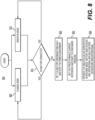
- FIG. 6 depicts an exemplary method for controlling a discharge of a bulk capacitor, according to one or more embodiments.
- method 600 for controlling a discharge of a bulk capacitor may include determining whether the charger is in a charge mode (operation 605) or an inverter mode (operation 640).
- method 600 may include determining whether discharge conditions are met (operation 610). When discharge conditions are not met (operation 610), method 600 may return to operation 605. When discharge conditions are met (operation 610), method 600 may include determining whether an AC voltage (line voltage) is present (operation 615). When AC voltage (line voltage) is not present (operation 615), method 600 may include operating the isolated DC-DC converter with a discharge current reference until the bulk capacitor is less than a threshold voltage, such as 60V, for example (operation 620).
- a threshold voltage such as 60V
- method 600 may include operating the isolated DC-DC converter with a discharge current reference until the bulk capacitor is equal to an AC peak voltage plus a hysteresis (operation 625).
- a peak voltage may be a peak voltage per input line multiplied by V3.
- method 600 may include determining whether discharge conditions are met (operation 645). When discharge conditions are not met (operation 645), method 600 may return to operation 640. When discharge conditions are met (operation 645), method 600 may include operating the PFC converter with a discharge current reference until the bulk capacitor is less than a threshold voltage, such as 60V, for example (operation 650).
- a threshold voltage such as 60V
- Method 600 may control a battery charger 100 including an alternating current (AC) to DC Power Factor Correction (PFC) converter 120 and a high voltage (HV) direct current (DC) to DC converter (HVDC) 130 connected to the PFC converter 120.
- PFC converter 120 may include a bulk capacitor 423 and a PFC converter switch 420 connectable to a line voltage 403.
- HVDC 130 may include one or more transformers 433 having a secondary side connectable to a battery 140, and a bridge driver connected to a primary side of the one or more transformers 433.
- Bridge driver may include a bridge driver switch 430.
- Method 600 may include performing, by one or more controllers 300, operations including controlling an operation of the bridge driver switch 430 to control a discharge of the bulk capacitor 423 to the battery 140 at an end of a grid-to-battery operation, the grid-to-battery operation to supply electric power from the line voltage 403 to the battery 140.
- the operations of method 600 may include controlling an operation of the bridge driver switch 430 to control a discharge of the bulk capacitor 423 to the battery 140 in one or more of the grid-to-battery operation or a battery-to-grid operation, the battery-to-grid operation to supply electric power from the battery 140 to a load of the line voltage 403.
- the operations of method 600 may include controlling an operation of the PFC converter switch 420 to control the discharge of the bulk capacitor 423 to a load of the line voltage 403 in the battery-to-grid operation.
- the operations of method 600 may include controlling the discharge of the bulk capacitor 423 to the battery 140 at the end of a grid-to-battery operation based on the battery 140 being connected to the HVDC 130, and no hardware-related faults in the PFC converter 120 or the HVDC 130.
- the operations of method 600 may include controlling the discharge of the bulk capacitor 423 to the battery 140 while a voltage of the bulk capacitor 423 is above a peak voltage of the line voltage 403 plus a hysteresis factor, when the line voltage 403 is connected to the PFC converter 120.
- the operations of method 600 may include controlling the discharge of the bulk capacitor 423 to the battery 140 while the voltage of the bulk capacitor 423 is above a threshold, when the line voltage 403 is disconnected from the PFC converter 120.
- the operations of method 600 may include controlling the discharge of the bulk capacitor 423 to the battery 140 based on a current threshold, and modifying the current threshold based on a change in a connection of PFC converter 120 or HVDC 130 to one or more of the line voltage 403 or the battery 140.
- Method 600 may include operating the bridge driver switch 430 to control a discharge of the bulk capacitor 423 to the battery 140 at an end of a grid-to-battery operation, the grid-to-battery operation to supply electric power from the line voltage 403 to the battery 140.
- FIG. 7 depicts an exemplary plot for a discharge of a bulk capacitor in a control system, according to one or more embodiments.
- plot 700 includes AC voltage 705, HVDC battery voltage 710, bulk capacitor voltage 715, and charger state 720.
- the period of time from 602 seconds to 633 seconds depicts a transition from an end of a charging operation of HVDC battery voltage 710 to approximately 775V, as indicated by charger state 720 transitioning between "forward_charging” and "forward_charging_derating" states, to an end of a discharge operation.
- charger state 720 transitions to a "standby” state (as a discharge condition for bulk capacitor discharge), and bulk capacitor voltage 715 decreases from approximately 725V to approximately 350V, based on AC voltage 705 at 240V.
- AC voltage 705 decreases to 0V.
- charger state 720 transitions to "bulk_discharge” state to discharge bulk capacitor voltage 715 to approximately 50V at 633 seconds.
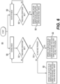
- FIG. 8 depicts an exemplary method for controlling a discharge of a high voltage filter capacitor, according to one or more embodiments.
- method 800 for controlling a discharge of a high voltage filter capacitor may include determining whether the charger is in a charge mode (operation 805) or an inverter mode (operation 810).
- method 800 may determine whether the HV battery is connected (operation 815). When the HV battery is connected (operation 815), method 800 may return to operation 805 and operation 810. When the HV battery is not connected (operation 815), method 800 may set the battery disconnection fault and stop the power conversion (operation 820). Next, method 800 may set the predetermined current reference and start the discharge process (operation 825). Next, method 800 may operate the DC-DC converter in a reverse mode (battery-to-grid), where the secondary (battery) side switches are operational and the primary (bulk capacitor) side switches are non-operational (operation 830).
- a reverse mode battery-to-grid
- Method 800 may control a battery charger 100 including an alternating current (AC) to DC Power Factor Correction (PFC) converter 120 and a high voltage (HV) direct current (DC) to DC converter (HVDC) 130 connected to the PFC converter 120.
- PFC converter 120 may include a bulk capacitor 423.
- PFC converter 120 may be connectable to a line voltage 403.
- HVDC 130 may include one or more transformers 433 having a secondary side connectable to a battery 140, a bridge rectifier connected to a secondary side of the one or more transformers 433, the bridge rectifier including a bridge rectifier switch 436, and a HV filter capacitor 439.
- Method 800 may include performing, by one or more controllers 300, operations including controlling an operation of the bridge rectifier switch 436 to control a discharge of the HV filter capacitor 439 to the bulk capacitor 423.
- the operations of method 800 may include controlling the operation of the bridge rectifier switch 436 to control the discharge of the HV filter capacitor 439 to the bulk capacitor 423 in each of a grid-to-battery operation and a battery-to-grid operation, the grid-to-battery operation to supply electric power from the line voltage 403 to the battery 140 and the battery-to-grid operation to supply electric power from the battery 140 to a load of the line voltage 403.
- the operations of method 800 may include determining whether the battery 140 is connected to the HVDC 130, and controlling the operation of the bridge rectifier switch 436 to control the discharge of the HV filter capacitor 439 to the bulk capacitor 423, when the battery 140 is determined to be disconnected from the HVDC 130.
- the operations of method 800 may include setting a battery disconnect fault and ending one or more of the grid-to-battery operation or the battery-to-grid operation, when the battery 140 is determined to be disconnected from the HVDC 130.
- the operations of method 800 may include determining a current threshold, and controlling the operation of the bridge rectifier switch 436 to control the discharge of the HV filter capacitor 439 to the bulk capacitor 423, when the one or more of the grid-to-battery operation or the battery-to-grid operation has ended.
- Method 600 may include operating the bridge rectifier switch 436 to control a discharge of the HV filter capacitor 439 to the bulk capacitor 423.
- One or more embodiments may provide a system that uses the HV DC-DC stage to discharge the bulk capacitor into the HV battery load during a forward charging (grid-to-battery) operation.
- One or more embodiments may control a current of the discharge using a current loop, without additional hardware.
- One or more embodiments may provide a system that, if the HV battery load is disconnected, uses a combination of the current and voltage loop to discharge the bulk capacitor while ensuring the HV bus capacitor voltage is within limits.
- One or more embodiments may provide a system that uses the PFC stage to discharge the bulk capacitor into the AC load during a reverse charging (battery-to-grid) operation.
- One or more embodiments may control a current of the discharge using a current loop, without additional hardware.
- One or more embodiments may provide a system that, if the AC load is disconnected, uses a combination of the current and voltage loop to discharge the bulk capacitor while ensuring the AC bus capacitor voltage is within limits.
- One or more embodiments may provide a system that, if the HV bus gets disconnected from the HV battery, discharges the energy stored in the HV bus into the bulk capacitor by operating the HV DC-DC converter in reverse mode.
- One or more embodiments may set an appropriate current reference to control the rate of the discharge.
- One or more embodiments may provide a system that transfers energy from the HV bus capacitor to the bulk capacitor with a very small increase in bulk capacitor voltage.
Landscapes
- Engineering & Computer Science (AREA)
- Power Engineering (AREA)
- Charge And Discharge Circuits For Batteries Or The Like (AREA)
Applications Claiming Priority (1)
| Application Number | Priority Date | Filing Date | Title |
|---|---|---|---|
| US18/323,497 US20240396360A1 (en) | 2023-05-25 | 2023-05-25 | Systems and methods for capacitor discharge control in forward and reverse charging |
Publications (1)
| Publication Number | Publication Date |
|---|---|
| EP4472018A1 true EP4472018A1 (de) | 2024-12-04 |
Family
ID=90789487
Family Applications (1)
| Application Number | Title | Priority Date | Filing Date |
|---|---|---|---|
| EP24170870.0A Pending EP4472018A1 (de) | 2023-05-25 | 2024-04-17 | Systeme und verfahren zur kondensatorentladungssteuerung beim vorwärts- und rückwärtsladen |
Country Status (2)
| Country | Link |
|---|---|
| US (1) | US20240396360A1 (de) |
| EP (1) | EP4472018A1 (de) |
Citations (3)
| Publication number | Priority date | Publication date | Assignee | Title |
|---|---|---|---|---|
| EP3050741B1 (de) * | 2010-10-14 | 2017-04-05 | Toyota Jidosha Kabushiki Kaisha | Bordnetzvorrichtung für ein fahrzeug, damit ausgestattetes fahrzeug und verfahren zur steuerung einer fahrzeugmontierten ladevorrichtung |
| CN112224050A (zh) * | 2019-06-30 | 2021-01-15 | 比亚迪股份有限公司 | 能量转换装置、动力系统以及车辆 |
| JP2023069257A (ja) * | 2021-11-05 | 2023-05-18 | 矢崎総業株式会社 | 車載充電器 |
-
2023
- 2023-05-25 US US18/323,497 patent/US20240396360A1/en active Pending
-
2024
- 2024-04-17 EP EP24170870.0A patent/EP4472018A1/de active Pending
Patent Citations (4)
| Publication number | Priority date | Publication date | Assignee | Title |
|---|---|---|---|---|
| EP3050741B1 (de) * | 2010-10-14 | 2017-04-05 | Toyota Jidosha Kabushiki Kaisha | Bordnetzvorrichtung für ein fahrzeug, damit ausgestattetes fahrzeug und verfahren zur steuerung einer fahrzeugmontierten ladevorrichtung |
| CN112224050A (zh) * | 2019-06-30 | 2021-01-15 | 比亚迪股份有限公司 | 能量转换装置、动力系统以及车辆 |
| JP2023069257A (ja) * | 2021-11-05 | 2023-05-18 | 矢崎総業株式会社 | 車載充電器 |
| US20230398889A1 (en) * | 2021-11-05 | 2023-12-14 | Yazaki Corporation | In-vehicle charger |
Also Published As
| Publication number | Publication date |
|---|---|
| US20240396360A1 (en) | 2024-11-28 |
Similar Documents
| Publication | Publication Date | Title |
|---|---|---|
| US12341440B2 (en) | Systems and methods for capacitor voltage control for inverter for electric vehicle | |
| US8963482B2 (en) | Power supply apparatus for electrically powered vehicle and method for controlling the same | |
| US12316155B2 (en) | Systems and methods for configurable DC-DC converter and battery charger | |
| US12395059B2 (en) | Systems and methods for integrated boost in high voltage and low voltage power conversion for battery charger | |
| US20250135926A1 (en) | Systems and methods for integrated high voltage and low voltage converter for bidirectional onboard battery charger | |
| US11336192B2 (en) | Three-phase power apparatus with bidirectional power conversion | |
| US12184185B2 (en) | Systems and methods for bridge mode transition and dynamic soft start for DC-DC converter and battery charger | |
| EP3915826B1 (de) | Verfahren und system zum fahrzeug-zu-fahrzeug-laden von elektrofahrzeugen | |
| EP4216416A1 (de) | Systeme und verfahren für bidirektionales batterieladegerät mit universeller eingangsleistungsversorgung | |
| EP4482008A1 (de) | Systeme und verfahren für gemeinsamen entwurf für einen ein-, geteilten und dreiphasigen wechselrichter für v2x-anwendungen | |
| EP4550644A1 (de) | Systeme und verfahren für integrierten wandler für bidirektionales bordbatterieladegerät für geteilte batterie | |
| EP4280449A1 (de) | Systeme und verfahren für konfigurierbaren primären und sekundären gleichstromwandler und batterieladegerät | |
| WO2013129231A1 (ja) | 電源装置 | |
| CN115693875A (zh) | 能够进行双向电力传输的充电器 | |
| EP4468558A1 (de) | Systeme und verfahren zur kondensatorentladungssteuerung beim vorwärts- und rückwärtsladen | |
| EP4472018A1 (de) | Systeme und verfahren zur kondensatorentladungssteuerung beim vorwärts- und rückwärtsladen | |
| US12294289B2 (en) | Systems and methods for resonant converter thermal and ripple current improvement using two stage voltage loop | |
| KR20240006343A (ko) | 전동화 차량 | |
| US20260109257A1 (en) | Systems and methods for bi-directional onboard charger for electric vehicle | |
| KR20240014854A (ko) | 전동화 차량 | |
| WO2025091036A1 (en) | Systems and methods for self-healing power converters |
Legal Events
| Date | Code | Title | Description |
|---|---|---|---|
| PUAI | Public reference made under article 153(3) epc to a published international application that has entered the european phase |
Free format text: ORIGINAL CODE: 0009012 |
|
| STAA | Information on the status of an ep patent application or granted ep patent |
Free format text: STATUS: THE APPLICATION HAS BEEN PUBLISHED |
|
| AK | Designated contracting states |
Kind code of ref document: A1 Designated state(s): AL AT BE BG CH CY CZ DE DK EE ES FI FR GB GR HR HU IE IS IT LI LT LU LV MC ME MK MT NL NO PL PT RO RS SE SI SK SM TR |
|
| RAP1 | Party data changed (applicant data changed or rights of an application transferred) |
Owner name: BORGWARNER US TECHNOLOGIES LLC |
|
| STAA | Information on the status of an ep patent application or granted ep patent |
Free format text: STATUS: REQUEST FOR EXAMINATION WAS MADE |
|
| 17P | Request for examination filed |
Effective date: 20250221 |
|
| P01 | Opt-out of the competence of the unified patent court (upc) registered |
Free format text: CASE NUMBER: UPC_APP_0002964_4472018/2026 Effective date: 20260128 |