EP4472012A1 - Dispositif de gestion de batterie de stockage d'énergie, système de batterie de stockage d'énergie et procédé de gestion de batterie de stockage d'énergie - Google Patents
Dispositif de gestion de batterie de stockage d'énergie, système de batterie de stockage d'énergie et procédé de gestion de batterie de stockage d'énergie Download PDFInfo
- Publication number
- EP4472012A1 EP4472012A1 EP22923888.6A EP22923888A EP4472012A1 EP 4472012 A1 EP4472012 A1 EP 4472012A1 EP 22923888 A EP22923888 A EP 22923888A EP 4472012 A1 EP4472012 A1 EP 4472012A1
- Authority
- EP
- European Patent Office
- Prior art keywords
- storage battery
- degradation
- controller
- target period
- degree
- Prior art date
- Legal status (The legal status is an assumption and is not a legal conclusion. Google has not performed a legal analysis and makes no representation as to the accuracy of the status listed.)
- Pending
Links
Images


Classifications
-
- H—ELECTRICITY
- H01—ELECTRIC ELEMENTS
- H01M—PROCESSES OR MEANS, e.g. BATTERIES, FOR THE DIRECT CONVERSION OF CHEMICAL ENERGY INTO ELECTRICAL ENERGY
- H01M10/00—Secondary cells; Manufacture thereof
- H01M10/42—Methods or arrangements for servicing or maintenance of secondary cells or secondary half-cells
- H01M10/48—Accumulators combined with arrangements for measuring, testing or indicating the condition of cells, e.g. the level or density of the electrolyte
-
- G—PHYSICS
- G01—MEASURING; TESTING
- G01R—MEASURING ELECTRIC VARIABLES; MEASURING MAGNETIC VARIABLES
- G01R31/00—Arrangements for testing electric properties; Arrangements for locating electric faults; Arrangements for electrical testing characterised by what is being tested not provided for elsewhere
- G01R31/36—Arrangements for testing, measuring or monitoring the electrical condition of accumulators or electric batteries, e.g. capacity or state of charge [SoC]
- G01R31/374—Arrangements for testing, measuring or monitoring the electrical condition of accumulators or electric batteries, e.g. capacity or state of charge [SoC] with means for correcting the measurement for temperature or ageing
-
- G—PHYSICS
- G01—MEASURING; TESTING
- G01R—MEASURING ELECTRIC VARIABLES; MEASURING MAGNETIC VARIABLES
- G01R31/00—Arrangements for testing electric properties; Arrangements for locating electric faults; Arrangements for electrical testing characterised by what is being tested not provided for elsewhere
- G01R31/36—Arrangements for testing, measuring or monitoring the electrical condition of accumulators or electric batteries, e.g. capacity or state of charge [SoC]
- G01R31/392—Determining battery ageing or deterioration, e.g. state of health
-
- H—ELECTRICITY
- H01—ELECTRIC ELEMENTS
- H01M—PROCESSES OR MEANS, e.g. BATTERIES, FOR THE DIRECT CONVERSION OF CHEMICAL ENERGY INTO ELECTRICAL ENERGY
- H01M10/00—Secondary cells; Manufacture thereof
- H01M10/42—Methods or arrangements for servicing or maintenance of secondary cells or secondary half-cells
- H01M10/425—Structural combination with electronic components, e.g. electronic circuits integrated to the outside of the casing
- H01M10/4257—Smart batteries, e.g. electronic circuits inside the housing of the cells or batteries
-
- H—ELECTRICITY
- H01—ELECTRIC ELEMENTS
- H01M—PROCESSES OR MEANS, e.g. BATTERIES, FOR THE DIRECT CONVERSION OF CHEMICAL ENERGY INTO ELECTRICAL ENERGY
- H01M10/00—Secondary cells; Manufacture thereof
- H01M10/42—Methods or arrangements for servicing or maintenance of secondary cells or secondary half-cells
- H01M10/44—Methods for charging or discharging
- H01M10/443—Methods for charging or discharging in response to temperature
-
- H—ELECTRICITY
- H01—ELECTRIC ELEMENTS
- H01M—PROCESSES OR MEANS, e.g. BATTERIES, FOR THE DIRECT CONVERSION OF CHEMICAL ENERGY INTO ELECTRICAL ENERGY
- H01M10/00—Secondary cells; Manufacture thereof
- H01M10/42—Methods or arrangements for servicing or maintenance of secondary cells or secondary half-cells
- H01M10/48—Accumulators combined with arrangements for measuring, testing or indicating the condition of cells, e.g. the level or density of the electrolyte
- H01M10/486—Accumulators combined with arrangements for measuring, testing or indicating the condition of cells, e.g. the level or density of the electrolyte for measuring temperature
-
- H02J7/80—
-
- H02J7/84—
-
- H02J7/977—
-
- H—ELECTRICITY
- H01—ELECTRIC ELEMENTS
- H01M—PROCESSES OR MEANS, e.g. BATTERIES, FOR THE DIRECT CONVERSION OF CHEMICAL ENERGY INTO ELECTRICAL ENERGY
- H01M10/00—Secondary cells; Manufacture thereof
- H01M10/42—Methods or arrangements for servicing or maintenance of secondary cells or secondary half-cells
- H01M10/425—Structural combination with electronic components, e.g. electronic circuits integrated to the outside of the casing
- H01M2010/4271—Battery management systems including electronic circuits, e.g. control of current or voltage to keep battery in healthy state, cell balancing
-
- Y—GENERAL TAGGING OF NEW TECHNOLOGICAL DEVELOPMENTS; GENERAL TAGGING OF CROSS-SECTIONAL TECHNOLOGIES SPANNING OVER SEVERAL SECTIONS OF THE IPC; TECHNICAL SUBJECTS COVERED BY FORMER USPC CROSS-REFERENCE ART COLLECTIONS [XRACs] AND DIGESTS
- Y02—TECHNOLOGIES OR APPLICATIONS FOR MITIGATION OR ADAPTATION AGAINST CLIMATE CHANGE
- Y02E—REDUCTION OF GREENHOUSE GAS [GHG] EMISSIONS, RELATED TO ENERGY GENERATION, TRANSMISSION OR DISTRIBUTION
- Y02E60/00—Enabling technologies; Technologies with a potential or indirect contribution to GHG emissions mitigation
- Y02E60/10—Energy storage using batteries
Definitions
- the present disclosure relates to a storage battery management device, a storage battery system, and a storage battery management method.
- Patent Literature 1 discloses a technology in which the degree of degradation of a storage battery is estimated based on information acquired without operating the battery in a dedicated operation state.
- Patent Literature 1 International Publication No. 2021/085433
- the controller is configured to acquire a current value flowing in a storage battery, a temperature of the storage battery, and a charge level of the storage battery in a target period, determine an operation mode of the storage battery in the target period based on the current value and the charge level, and estimate a degree of degradation of the storage battery in the target period based on the operation mode and the temperature.
- the target period is divided by switching of operating states of the storage battery including charging, discharging, and retaining.
- a storage battery system includes a storage battery and a storage battery management device.
- the storage battery management device includes a controller.
- the controller is configured to
- the target period is divided by switching of operating states of the storage battery including charging, discharging, and retaining.
- a storage battery management method is to be performed by a storage battery management device including a controller.
- the method includes
- the target period is divided by switching of operating states of the storage battery including charging, discharging, and retaining.
- a storage battery management device a storage battery system, and a storage battery management method that can estimate the degree of degradation of a storage battery with high accuracy can be provided.
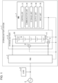
- FIG. 1 is a schematic configuration diagram illustrating an example of a storage battery system 1 according to an embodiment of the present disclosure.
- the storage battery system 1 includes a power conditioner 2, a storage battery 3, a current sensor 4, a temperature sensor 5, a voltage sensor 6, and a storage battery management device 7.
- the power conditioner 2 is also called a PCS (power conditioning system).
- the storage battery management device 7 is also called a BMS (buttery management system).
- the storage battery 3 is connected to outside the storage battery system 1, such as to a power system 8 and a load 9, via the power conditioner 2.
- the storage battery system 1 can supply power charged to the storage battery 3 to the power system 8 and the load 9, etc.
- the storage battery system 1 can also charge the storage battery 3 with power supplied from the power system 8 or another source.
- the power conditioner 2, the storage battery 3, the current sensor 4, the temperature sensor 5, the voltage sensor 6, and the storage battery management device 7 are connected to each other in a wired or wireless manner via a network such as CAN (controller area network).
- CAN controller area network
- the storage battery system 1 is described as including one of each of the power conditioner 2, the storage battery 3, the current sensor 4, the temperature sensor 5, the voltage sensor 6, and the storage battery management device 7, but the storage battery system 1 may include any number of each of these components.
- the power conditioner 2 converts DC power to be discharged to the outside from the storage battery 3 into AC power.
- the power conditioner 2 converts AC power to be supplied to the storage battery 3 from the outside into DC power.
- the storage battery 3 is a chargeable/dischargeable battery such as a lithium-ion battery.
- the storage battery 3 includes a storage battery module 32 including one or more cells 31.
- the storage battery 3 can store power in the cells 31 of the storage battery module 32 and discharge power from the cells 31.
- multiple cells 31 are described as being connected in series in the storage battery module 32, but the cells 31 may be connected in parallel with each other.
- multiple storage battery modules 32 may be connected in series or parallel with each other.
- the current sensor 4 measures a current value flowing in the storage battery 3.
- the current value flowing in the storage battery 3 includes at least one of a current value input to the storage battery 3 or a current value output from the storage battery 3.
- the current sensor 4 transmits the measured current value to the storage battery management device 7, for example, as the current value flowing in the storage battery 3.
- the current sensor 4 is connected in series with one terminal of the storage battery module 32.
- the current sensor 4 is not limited to being connected to one terminal of the storage battery module 32, and may be connected to any position where the current value flowing in the storage battery 3 can be measured.
- the temperature sensor 5 measures the temperature of the storage battery 3.
- the temperature sensor 5 transmits the measured temperature to the storage battery management device 7, for example, as the temperature of the storage battery 3.
- the temperature sensor 5 is installed on an outer surface of one terminal of the storage battery module 32.
- the temperature sensor 5 is not limited to being installed on the outer surface of one terminal of the storage battery module 32, and may be installed at any position where the temperature of the storage battery 3 can be measured.
- the voltage sensor 6 measures a voltage value of the storage battery 3.
- the voltage sensor 6 transmits the measured voltage value to the storage battery management device 7, for example, as the voltage value of the storage battery 3.
- Examples of the voltage value of the storage battery 3 include voltage values during charging and discharging and the value of the open circuit voltage when no current is flowing.
- the voltage sensor 6 is connected in parallel with both terminals of the storage battery module 32.
- the voltage sensor 6 is not limited to being connected in parallel with both terminals of the storage battery module 32, and may be installed at any position where the voltage value of the storage battery 3 can be measured.
- the storage battery management device 7 manages the storage battery 3.
- the storage battery management device 7 controls the storage battery 3 by, for example, turning the power on or off or transmitting information from the storage battery 3 to the storage battery management device 7.
- the storage battery management device 7 communicates with the current sensor 4, the temperature sensor 5, and the voltage sensor 6, etc., and acquires the current value flowing in the storage battery 3, the temperature of the storage battery 3, and the charge level of the storage battery 3.
- the storage battery management device 7 determines an operation mode of the storage battery and estimates the degree of degradation based on the acquired current value, temperature, and charge level of the storage battery 3.
- the degree of degradation of the storage battery 3 can be estimated based on information acquired without operating the storage battery 3 in a dedicated operation state.
- the degree of degradation of the storage battery 3 is expressed using SOH (state of health).
- SOH is the ratio (%) of the current full charge capacity (FCC) to the design capacity (DC).
- the design capacity may be, for example, the initial value of the full charge capacity of the storage battery 3 as determined by the manufacturer of the storage battery 3.
- the charge level of the storage battery 3 is expressed using SOC (states of charge). SOC is the ratio (%) of the present charge to the present full charge capacity.
- an operation state of the storage battery 3 is also referred to as an operation mode in the following description.
- Operation modes of the storage battery 3 include, for example, operating modes, which are operation states in which the storage battery 3 is charging or discharging, and retaining modes, which are operation states in which the storage battery 3 retains power.
- the storage battery management device 7 includes a controller 71, a communication unit 72, a storage unit 73, an output unit 74, and an input unit 75.
- the controller 71, the communication unit 72, the storage unit 73, the output unit 74, and the input unit 75 are connected to each other in a wired or wireless manner so as to be able to communicate with each other.
- the controller 71 includes one or more processors.
- the processor may be a general-purpose processor such as a CPU (central processing unit) or a dedicated processor specialized for particular processing.
- the controller 71 is not limited to a processor and may include one or more dedicated circuits.
- a dedicated circuit may be, for example, a FPGA (field-programmable gate array) or an ASIC (application specific integrated circuit).
- the controller 71 controls the communication unit 72, the storage unit 73, the output unit 74, and the input unit 75, as described above, in order to realize the functions of the storage battery management device 7. Characteristic control in this embodiment performed by the controller 71 will be further described later.
- the communication unit 72 includes one or more communication modules.
- the communication module is, for example, a CAN communication module, a wired LAN (local area network) communication module, or a wireless LAN communication module.
- the storage battery management device 7 can communicate with the power conditioner 2, the storage battery 3, the current sensor 4, the temperature sensor 5, and the voltage sensor 6, etc. included in the storage battery system 1 via the communication unit 72.
- the storage unit 73 may be a semiconductor memory, a magnetic memory, or an optical memory, for example.
- the storage unit 73 may be a cache memory of a processor included in the controller 71.
- the storage unit 73 may be a volatile storage device or a nonvolatile storage device.
- the storage unit 73 stores system programs, application programs, embedded software, information, and so on for realizing the functions of the storage battery management device 7.
- the output unit 74 outputs information in the form of images, sound, and so on.
- the output unit 74 includes an output device such as a display and a speaker.
- the input unit 75 accepts input operations.
- the input unit 75 includes an input device such as a touch panel and a remote controller.
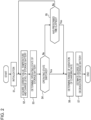
- FIG. 2 illustrates a flowchart of an example of this processing performed by the storage battery management device 7.
- FIG. 3 illustrates a flowchart detailing part of the processing illustrated in FIG. 2 .
- Step S1 the controller 71 performs initialization necessary for this processing.
- the controller 71 acquires an initial value of the charge level of the storage battery 3 and an initial value of the degree of degradation stored in the storage unit 73.
- the initial value of the charge level and the initial value of the degree of degradation are values that are respectively considered to be the charge level and the degree of degradation of the storage battery 3 at the start of this processing.
- the initial value of the charge level and the initial value of the degree of degradation of the storage battery 3 are, for example, the charge level and the degree of degradation of the storage battery 3 calculated by processing the same as this processing performed previously.
- the controller 71 may acquire the initial values using different processing from this processing. For example, the controller 71 may use, as the initial values, the actual measured charge level and the actual measured degree of degradation of the storage battery 3 measured by operating the storage battery 3 in a dedicated operation state.
- the controller 71 stores the very first start date and time of a target period during which the estimation of the degree of degradation of the storage battery 3 is performed in this processing. Specifically, the controller 71 stores the date and time at which this processing is started in the storage unit 73.
- the target period during which the estimation of the degree of degradation of the storage battery 3 is performed in this processing is hereafter also referred to simply as the "target period”.
- Step S2 the controller 71 acquires the current value flowing in the storage battery 3, the temperature of the storage battery 3, and the charge level of the storage battery 3.
- the controller 71 communicates with the current sensor 4 via the communication unit 72 and receives the current value measured by the current sensor 4 at intervals of one second, for example, as the current value flowing in the storage battery 3.
- the controller 71 communicates with the temperature sensor 5 via the communication unit 72 and receives the temperature measured by the temperature sensor 5 at intervals of one second, for example, as the temperature of the storage battery 3.
- the controller 71 calculates the charge level of the storage battery 3 based on the initial value of the charge level and the received current value flowing in the storage battery 3 by using a current integration method, for example.
- the controller 71 stores the current value, temperature, and charge level of the storage battery 3 in the storage unit 73 as information on the current value, temperature, and charge level of the storage battery 3 acquired in the target period.
- the methods used by the controller 71 to acquire the current value flowing in the storage battery 3, the temperature of the storage battery 3, and the charge level of the storage battery 3 are not limited to the examples described above.
- the controller 71 may communicate with the voltage sensor 6 and calculate the charge level of the storage battery 3 based on the value of the open circuit voltage of the storage battery 3.
- Step S3 the controller 71 determines whether the operation mode is an operating mode in which charging or discharging is performed or a retaining mode in which power is retained.
- the controller 71 determines the operating state of the storage battery 3 based on at least one of the acquired current value or charge level, for example.
- the operating states include charging, discharging, and retaining. If the operating state of storage battery 3 is retaining, the controller 71 determines that the operation mode is a retaining mode. If the operating state of the storage battery 3 is charging or discharging, the controller 71 determines that the operation mode is an operating mode.
- the controller 71 may determine the operating state of the storage battery 3 by estimating changes in the storage battery 3 by reading and comparing the past current values, charge levels, etc. stored in the storage unit 73. For example, the controller 71 may determine that the storage battery 3 is being input with or is outputting a prescribed amount of power or more and the operation mode is an operating mode if the target period includes a current value whose absolute value is greater than or equal to a prescribed value. On the other hand, the controller 71 may determine that the storage battery 3 is retaining power and the operation mode is a retaining mode if the current values acquired over the target period do not include a current value whose absolute value is greater than or equal to the prescribed value.
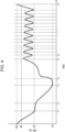
- FIG. 4 is a diagram illustrating an example of changes in the charge level of the storage battery 3 that occur over time.
- FIG. 5 is a diagram illustrating examples of operation modes determined in accordance with the changes in the charge level in FIG. 4 .
- the vertical axis of FIG. 4 represents the charge level (SOC) of the storage battery 3.
- the horizontal axis of FIG. 4 represents time, and times t 1 , t 2 , t 3 , t 4 , t 5 , t 6 , ..., and t k are illustrated.
- k is an integer greater than or equal to 7.
- the controller 71 acquires the charge level at timings including these times. For example, the controller 71 determines the operating state, as illustrated in FIG.
- the controller 71 determines that the operating state is charging, as illustrated in FIG. 5 .
- the controller 71 determines the operating state of the storage battery 3 in a prescribed time.
- the prescribed time is set to include timings where changes are indicated in the charge level such as the times t 1 , t 2 , t 3 , t 4 , t 5 , t 6 , ..., and t k .
- the prescribed time is every 10 minutes, for example.
- the controller 71 stores the determined operating state of the storage battery 3 in the storage unit 73 in association with the time at which the determination was made.
- the "applicable operation mode", "SOC range”, and "applicable category" in FIG. 5 are described below.
- Step S4 the controller 71 determines whether or not the operating state of the storage battery 3 has switched.
- Switching of the operating state of the storage battery 3 means that the operating state becomes a different operating state from the previous operating state. Switching of the operating state of the storage battery 3 includes changing from charging to discharging or retaining, changing from discharging to retaining or charging, and changing from retaining to charging or discharging.
- the controller 71 determines the range of variation of the charge level and estimates the degree of degradation of the storage battery 3.
- Step S5 Even if the operating state of the storage battery 3 has not switched (No in Step S4), the controller 71 determines in Step S5 whether or not the prescribed time has elapsed. When the prescribed time has elapsed (Yes in Step S5), the controller 71 determines the range of variation of the charge level and estimates the degree of degradation of the storage battery 3. However, when the prescribed time has not elapsed (No in Step S5), the controller 71 returns to the processing of Step S2.
- Step S5 the date and time at the time of the determination are stored in the storage unit 73 as the end date and time of the target period and the start date and time of the next target period.
- the times t 1 , t 2 , t 3 , t 4 , t 5 , t 6 , ..., and t k in the example in FIG. 4 correspond to the timings of switching of the operating state of the storage battery 3.
- the controller 71 divides the target period at the times t 1 , t 2 , t 3 , t 4 , t 5 , t 6 , ..., and t k , where the operating state of the storage battery 3 is switched.
- the controller 71 determines the range of variation of the charge level and estimates the degree of degradation of the storage battery 3 for a target period with the time t 2 as the start date and time and the time t 3 as the end date and time. Furthermore, for example, for the time t 4 , the controller 71 determines the range of variation of the charge level and estimates the degree of degradation of the storage battery 3 for a target period with the time t 3 as the start date and time and the time t 4 as the end date and time. In this embodiment, the controller 71 estimates the degree of degradation of the storage battery 3 in the target periods, which are divided by the switching of the operating state of the storage battery 3 or at prescribed times.
- the storage battery management device 7 and the storage battery system 1 can improve estimation accuracy of the degree of degradation of the storage battery 3 due to the estimation of the degree of degradation of storage battery 3 being performed over relatively short target periods.
- Step S6 the controller 71 determines the range of variation of the charge level of the storage battery 3 during the target period.
- the controller 71 determines the range of variation of the charge level of the storage battery 3 during the target period based on the charge level included in information acquired during the target period, which is stored in the storage unit 73.
- the controller 71 extracts the maximum value and the minimum value from the charge level acquired in the target period and sets the range of variation of the charge level as being from the minimum value to the maximum value.
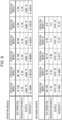
- the controller 71 stores multiple operation modes having different SOC ranges in the storage unit 73 in advance, as illustrated in FIG. 6 .
- multiple operation modes (operation modes 1 to 6) corresponding to operating modes and multiple operation modes (operation modes 7 to 11) corresponding to retaining modes are stored in the storage unit 73.
- the controller 71 selects one operation mode so that the range of variation of the charge level based on the maximum value and the minimum value extracted in the target period is included in the SOC range of the operation mode.
- the controller 71 may store the selected one operation mode in the storage unit 73 in association with the target period.
- operation mode 2 is one of multiple operation modes corresponding to operating modes, and defines an index and coefficients used to calculate normal degradation.
- the controller 71 selects operation mode 9, in which the SOC range is 30 to 70 [%], as illustrated in FIG. 5 .
- operation mode 9 is one of multiple operation modes corresponding to retaining modes, and defines an index and coefficients used to calculate retention degradation.
- operation mode 1 is one of multiple operation modes corresponding to operating modes, and defines an index and coefficients used to calculate normal degradation.
- Rate-dependent degradation may be calculated in addition to normal degradation when the operating state is charging, as illustrated in the "applicable category" section at the time t 5 and the time t k in FIG. 5 . The rate-dependent degradation will be described in detail later.
- Step S7 the controller 71 estimates the degree of degradation of the storage battery 3 during the target period.
- the controller 71 estimates the degree of degradation of the storage battery 3 during the target period based on the operation mode of storage battery 3 during the target period stored in the storage unit 73 and the temperature included in the information acquired during the target period.
- the controller 71 calculates the following Equation (1) based on Arrhenius' law and uses the calculation result to estimate the degree of degradation of the storage battery 3.
- the coefficient b which represents the slope
- the coefficient c which represents the intercept
- Equation (2) if the capacity degradation at a certain elapsed time t is CAP (n-1) and the capacity degradation at an elapsed time t+ ⁇ t, at which a time interval ⁇ t has further elapsed from the elapsed time t, is CAP n , the capacity degradation CAP (n-1) and CAP n are expressed by the following Equations (3) and (4), respectively.
- the capacity degradation CAP n the degree of degradation SOH (n-1) of the storage battery 3 at the elapsed time t and the degree of degradation SOH n at the elapsed time t+ ⁇ t satisfy the following relationships.
- the degree of degradation SOH n of the storage battery 3 can be calculated from the degree of degradation SOH (n-1) and the capacity degradation CAP n .
- the reaction rate constant ⁇ and the degradation index ⁇ in Equation (5) depend on the state in which the storage battery 3 is charging, discharging or retaining power, the charge level of the storage battery 3, the temperature of the storage battery 3, and so on. Therefore, in this embodiment, the coefficients and index are determined and stored in advance based on the degree of degradation of the storage battery 3, which is measured by operating the storage battery 3 while changing the conditions of the charge level, the temperature, and the operation mode of the storage battery 3.
- the pre-determined coefficients and index are, specifically, the coefficients (b, c) of the reaction rate constant ⁇ and the degradation index ⁇ , which are associated with each of the multiple operation modes illustrated in FIG. 6 .
- Step S11 the controller 71 sets the initial value of the degree of degradation of the storage battery 3 acquired in Step 1 as SOH 0 and sets 0 as the initial value of the number of iterations n.
- the controller 71 performs the processing from Step S12 to Step S17 for all of the temperatures and current values of the X storage batteries 3 acquired in the target period. In this way, the controller 71 can calculate the degree of degradation SOH n of the storage battery 3 at a time point n (n is a natural number from 1 to X) for each time interval ⁇ t from the degree of degradation SOH 0 of the storage battery 3 at the first starting point in the target period.
- Step S12 the controller 71 increments the number of repetitions n by 1.
- Step S13 the controller 71 calculates the SOH n at the time point at which the time ⁇ t ⁇ n has elapsed as described above using the coefficients of the selected operation mode.
- the SOH n calculated in Step S13 corresponds to the degree of degradation of normal degradation or retention degradation. For example, when multiple temperatures of multiple cells 31 are available, the largest temperature is selected and used as the temperature used in the calculation of the degree of degradation for normal degradation or retention degradation rather than averaging these temperatures. By selecting and using the largest temperature from among the multiple temperatures of the multiple cells 31, the degree of degradation SOH n of the storage battery 3 can be calculated more precisely.
- the controller 71 calculates the rate-dependent degree of degradation when the operating state is charging (Yes in Step S14) and the average current value is greater than or equal to the threshold (Yes in Step S15).
- the rate-dependent degree of degradation is a degree of degradation corresponding to advanced degradation, and is a value that modifies the normal degree of degradation.
- the controller 71 can calculate the degree of degradation SOH n of the storage battery 3 with high accuracy by including temperature-dependent changes caused by rate-dependent degradation.
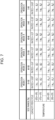
- FIG. 7 illustrates a table of coefficients and other factors for determining the amount of change with temperature due to rate-dependent degradation in this embodiment. Based on the operation mode and temperature, the controller 71 extracts the reaction rate constant ⁇ and the degradation index ⁇ from FIG.
- Step S17 the controller 71 determines whether or not the estimation processing of the degree of degradation from Step S12 to Step S17 has been repeated X times. If the estimation processing of the degree of degradation is determined to not have been repeated X times (No in Step S17), the controller 71 repeats the processing from Step S12. On the other hand, if the estimation processing of the degree of degradation is determined to have been repeated X times (Yes in Step S17), the controller 71 stores the degree of degradation SOHx of the storage battery 3 at time point X in the storage unit 73 as the degree of degradation of the storage battery 3 at the end of the target period. The controller 71 may output the estimated degree of degradation of the storage battery 3 to the output unit 74.
- Step S7 the controller 71 terminates this processing. After completing this processing, the controller 71 may start the processing again from Step S1.
- the storage battery management device, the storage battery system, and the storage battery management method can estimate the degree of degradation of storage batteries with high accuracy via the above configurations and processes.
- the storage battery system 1 is described as including one of each of the current sensor 4, the temperature sensor 5, and the voltage sensor 6, but the storage battery system 1 is not limited to this configuration.
- the storage battery system 1 may include multiple current sensors 4, multiple temperature sensors 5, or multiple voltage sensors 6.
- the current sensor 4, the temperature sensor 5, or the voltage sensor 6 does not need to be provided for each storage battery 3, and may instead be provided for each cell 31 or for each storage battery module 32.
- the storage battery management device 7 may calculate the current, temperature, or voltage of the storage battery 3 by calculating an average value or representative value from the values measured by multiple current sensors 4, multiple temperature sensors 5, or multiple voltage sensors 6.
- all or some of the functions or processing described as the functions or processing of the storage battery management device 7 in the embodiment described above may be realized as the functions or processing of a computer, such as a smart phone or personal computer.
- a program describing processing content that realizes each function of the storage battery management device 7 according to this embodiment is stored in the memory of a computer, and the program is read out and executed by a processor of the computer. Therefore, the processing of the storage battery management device 7 according to this embodiment can also be realized as a program that can be executed by a processor.
- the storage battery management device 7 is provided so as to be separate from the power conditioner 2 and the storage battery 3 is illustrated, but this does not need to be the case.
- the power conditioner 2 or the storage battery 3 may function as the storage battery management device 7.
- an EMS (energy management system) such as a HEMS (home energy management system) and a BEMS (building energy management system) may function as the storage battery management device 7.
- the power conditioner 2, the storage battery 3, or the EMS may be configured to include a computer having the configurations and functions described above as the configurations and functions of the storage battery management device 7.
Landscapes
- Engineering & Computer Science (AREA)
- Manufacturing & Machinery (AREA)
- Chemical & Material Sciences (AREA)
- Chemical Kinetics & Catalysis (AREA)
- Electrochemistry (AREA)
- General Chemical & Material Sciences (AREA)
- Physics & Mathematics (AREA)
- General Physics & Mathematics (AREA)
- Microelectronics & Electronic Packaging (AREA)
- Charge And Discharge Circuits For Batteries Or The Like (AREA)
- Secondary Cells (AREA)
Applications Claiming Priority (1)
| Application Number | Priority Date | Filing Date | Title |
|---|---|---|---|
| PCT/JP2022/003423 WO2023145024A1 (fr) | 2022-01-28 | 2022-01-28 | Dispositif de gestion de batterie de stockage d'énergie, système de batterie de stockage d'énergie et procédé de gestion de batterie de stockage d'énergie |
Publications (2)
| Publication Number | Publication Date |
|---|---|
| EP4472012A1 true EP4472012A1 (fr) | 2024-12-04 |
| EP4472012A4 EP4472012A4 (fr) | 2025-11-19 |
Family
ID=87470936
Family Applications (1)
| Application Number | Title | Priority Date | Filing Date |
|---|---|---|---|
| EP22923888.6A Pending EP4472012A4 (fr) | 2022-01-28 | 2022-01-28 | Dispositif de gestion de batterie de stockage d'énergie, système de batterie de stockage d'énergie et procédé de gestion de batterie de stockage d'énergie |
Country Status (5)
| Country | Link |
|---|---|
| US (1) | US20250102591A1 (fr) |
| EP (1) | EP4472012A4 (fr) |
| JP (1) | JP7710052B2 (fr) |
| CN (1) | CN118575387A (fr) |
| WO (1) | WO2023145024A1 (fr) |
Families Citing this family (1)
| Publication number | Priority date | Publication date | Assignee | Title |
|---|---|---|---|---|
| WO2021117560A1 (fr) * | 2019-12-13 | 2021-06-17 | 京セラ株式会社 | Dispositif de stockage d'électricité et procédé de stockage d'électricité |
Family Cites Families (4)
| Publication number | Priority date | Publication date | Assignee | Title |
|---|---|---|---|---|
| WO2016092811A1 (fr) * | 2014-12-10 | 2016-06-16 | 株式会社Gsユアサ | Dispositif d'estimation d'état d'élément de stockage d'énergie et procédé d'estimation d'état d'élément de stockage d'énergie |
| US10547180B2 (en) * | 2016-11-04 | 2020-01-28 | Battelle Memorial Institute | Battery system management through non-linear estimation of battery state of charge |
| JP7235852B2 (ja) * | 2019-09-06 | 2023-03-08 | 株式会社東芝 | 情報処理装置、情報処理方法及び情報処理システム |
| WO2021085433A1 (fr) | 2019-10-29 | 2021-05-06 | 京セラ株式会社 | Dispositif de gestion de batterie de stockage d'énergie, système de batterie de stockage d'énergie et procédé de gestion de batterie de stockage d'énergie |
-
2022
- 2022-01-28 US US18/730,786 patent/US20250102591A1/en active Pending
- 2022-01-28 EP EP22923888.6A patent/EP4472012A4/fr active Pending
- 2022-01-28 WO PCT/JP2022/003423 patent/WO2023145024A1/fr not_active Ceased
- 2022-01-28 JP JP2023576539A patent/JP7710052B2/ja active Active
- 2022-01-28 CN CN202280089805.0A patent/CN118575387A/zh active Pending
Also Published As
| Publication number | Publication date |
|---|---|
| WO2023145024A1 (fr) | 2023-08-03 |
| EP4472012A4 (fr) | 2025-11-19 |
| JPWO2023145024A1 (fr) | 2023-08-03 |
| JP7710052B2 (ja) | 2025-07-17 |
| US20250102591A1 (en) | 2025-03-27 |
| CN118575387A (zh) | 2024-08-30 |
Similar Documents
| Publication | Publication Date | Title |
|---|---|---|
| EP3663780B1 (fr) | Procédé de calcul d'état de détérioration et dispositif de calcul d'état de détérioration | |
| CN102124354B (zh) | 使用电池电压行为估计电池电阻特性的装置及方法 | |
| KR101187766B1 (ko) | 배터리 셀의 전압 변화 거동을 이용한 셀 밸런싱 장치 및 방법 | |
| US8046181B2 (en) | Apparatus and method for estimating state of health of battery based on battery voltage variation pattern | |
| CN106662620B (zh) | 电池状态探测装置、二次电池系统、存储介质、电池状态探测方法 | |
| CN114585936B (zh) | 用于确定充电电池的荷电状态和健康状态的方法和装置 | |
| CN111707955B (zh) | 电池剩余寿命的估算方法、装置和介质 | |
| EP4040569A1 (fr) | Dispositif d'estimation d'état de batterie | |
| CN108957337A (zh) | 电池健康状态的确定方法、装置、存储介质和电子设备 | |
| KR20120065293A (ko) | 배터리 셀의 전압 변화 거동을 이용한 셀 밸런싱 장치 및 방법 | |
| JP2021524138A (ja) | バッテリー管理装置、バッテリー管理方法及びバッテリーパック | |
| JP6991247B2 (ja) | 蓄電装置、蓄電システム、電源システム、及び蓄電装置の制御方法 | |
| CN111426960A (zh) | 储能锂电池荷电状态监控方法与装置 | |
| JP2021524127A (ja) | バッテリー管理装置、バッテリー管理方法及びバッテリーパック | |
| EP4472012A1 (fr) | Dispositif de gestion de batterie de stockage d'énergie, système de batterie de stockage d'énergie et procédé de gestion de batterie de stockage d'énergie | |
| CN114460475B (zh) | 电池ocv确定方法及装置、电池soc的估算方法 | |
| JP2022044172A (ja) | 複数の電池に関する判定装置、蓄電システム、判定方法及び判定プログラム | |
| CN114616740B (zh) | 蓄电池管理装置、蓄电池系统以及蓄电池管理方法 | |
| EP4083641A1 (fr) | Dispositif semi-conducteur et procédé de surveillance de capacité de réserve de batterie | |
| KR100911315B1 (ko) | 배터리 전압 거동을 이용한 배터리 저항 특성 추정 장치 및방법 | |
| JP2016223964A (ja) | 蓄電デバイスの劣化診断装置及び劣化診断方法 | |
| CN118501705A (zh) | 充电剩余时间估计方法、装置、控制器和车辆 | |
| KR102646373B1 (ko) | 배터리 관리 시스템, 배터리 관리 방법 및 배터리 팩 | |
| EP4592696A1 (fr) | Procédé d'estimation d'état de santé (soh) de batterie et système de batterie fournissant celui-ci | |
| JP7692525B2 (ja) | Soc推定装置、プログラム及びsoc推定方法 |
Legal Events
| Date | Code | Title | Description |
|---|---|---|---|
| STAA | Information on the status of an ep patent application or granted ep patent |
Free format text: STATUS: THE INTERNATIONAL PUBLICATION HAS BEEN MADE |
|
| PUAI | Public reference made under article 153(3) epc to a published international application that has entered the european phase |
Free format text: ORIGINAL CODE: 0009012 |
|
| STAA | Information on the status of an ep patent application or granted ep patent |
Free format text: STATUS: REQUEST FOR EXAMINATION WAS MADE |
|
| 17P | Request for examination filed |
Effective date: 20240722 |
|
| AK | Designated contracting states |
Kind code of ref document: A1 Designated state(s): AL AT BE BG CH CY CZ DE DK EE ES FI FR GB GR HR HU IE IS IT LI LT LU LV MC MK MT NL NO PL PT RO RS SE SI SK SM TR |
|
| DAV | Request for validation of the european patent (deleted) | ||
| DAX | Request for extension of the european patent (deleted) | ||
| A4 | Supplementary search report drawn up and despatched |
Effective date: 20251017 |
|
| RIC1 | Information provided on ipc code assigned before grant |
Ipc: H02J 7/00 20060101AFI20251013BHEP Ipc: H01M 10/48 20060101ALI20251013BHEP Ipc: H01M 10/42 20060101ALI20251013BHEP Ipc: H01M 10/44 20060101ALI20251013BHEP |