EP4472007A1 - Carbon emission demand response processing method and apparatus, and computer device and storage medium - Google Patents

Carbon emission demand response processing method and apparatus, and computer device and storage medium Download PDF

Info

Publication number
EP4472007A1
EP4472007A1 EP22923307.7A EP22923307A EP4472007A1 EP 4472007 A1 EP4472007 A1 EP 4472007A1 EP 22923307 A EP22923307 A EP 22923307A EP 4472007 A1 EP4472007 A1 EP 4472007A1
Authority
EP
European Patent Office
Prior art keywords
power
power flow
carbon emission
demand response
loads
Prior art date
Legal status (The legal status is an assumption and is not a legal conclusion. Google has not performed a legal analysis and makes no representation as to the accuracy of the status listed.)
Pending
Application number
EP22923307.7A
Other languages
German (de)
French (fr)
Other versions
EP4472007A4 (en
Inventor
Jia Cao
Xiong Liu
Long Wang
Wenguang Chen
Zhouyan WEI
Tao He
Xiaohui TAN
Chengyong FU
Current Assignee (The listed assignees may be inaccurate. Google has not performed a legal analysis and makes no representation or warranty as to the accuracy of the list.)
Zhuzhou CRRC Times Electric Co Ltd
Original Assignee
Zhuzhou CRRC Times Electric Co Ltd
Priority date (The priority date is an assumption and is not a legal conclusion. Google has not performed a legal analysis and makes no representation as to the accuracy of the date listed.)
Filing date
Publication date
Application filed by Zhuzhou CRRC Times Electric Co Ltd filed Critical Zhuzhou CRRC Times Electric Co Ltd
Publication of EP4472007A1 publication Critical patent/EP4472007A1/en
Publication of EP4472007A4 publication Critical patent/EP4472007A4/en
Pending legal-status Critical Current

Links

Images

Classifications

    • GPHYSICS
    • G06COMPUTING OR CALCULATING; COUNTING
    • G06FELECTRIC DIGITAL DATA PROCESSING
    • G06F17/00Digital computing or data processing equipment or methods, specially adapted for specific functions
    • G06F17/10Complex mathematical operations
    • G06F17/11Complex mathematical operations for solving equations, e.g. nonlinear equations, general mathematical optimization problems
    • GPHYSICS
    • G06COMPUTING OR CALCULATING; COUNTING
    • G06FELECTRIC DIGITAL DATA PROCESSING
    • G06F17/00Digital computing or data processing equipment or methods, specially adapted for specific functions
    • G06F17/10Complex mathematical operations
    • G06F17/15Correlation function computation including computation of convolution operations
    • GPHYSICS
    • G06COMPUTING OR CALCULATING; COUNTING
    • G06QINFORMATION AND COMMUNICATION TECHNOLOGY [ICT] SPECIALLY ADAPTED FOR ADMINISTRATIVE, COMMERCIAL, FINANCIAL, MANAGERIAL OR SUPERVISORY PURPOSES; SYSTEMS OR METHODS SPECIALLY ADAPTED FOR ADMINISTRATIVE, COMMERCIAL, FINANCIAL, MANAGERIAL OR SUPERVISORY PURPOSES, NOT OTHERWISE PROVIDED FOR
    • G06Q10/00Administration; Management
    • G06Q10/04Forecasting or optimisation specially adapted for administrative or management purposes, e.g. linear programming or "cutting stock problem"
    • GPHYSICS
    • G06COMPUTING OR CALCULATING; COUNTING
    • G06QINFORMATION AND COMMUNICATION TECHNOLOGY [ICT] SPECIALLY ADAPTED FOR ADMINISTRATIVE, COMMERCIAL, FINANCIAL, MANAGERIAL OR SUPERVISORY PURPOSES; SYSTEMS OR METHODS SPECIALLY ADAPTED FOR ADMINISTRATIVE, COMMERCIAL, FINANCIAL, MANAGERIAL OR SUPERVISORY PURPOSES, NOT OTHERWISE PROVIDED FOR
    • G06Q50/00Information and communication technology [ICT] specially adapted for implementation of business processes of specific business sectors, e.g. utilities or tourism
    • G06Q50/06Energy or water supply
    • HELECTRICITY
    • H02GENERATION; CONVERSION OR DISTRIBUTION OF ELECTRIC POWER
    • H02JELECTRIC POWER NETWORKS; CIRCUIT ARRANGEMENTS OR SYSTEMS FOR SUPPLYING OR DISTRIBUTING ELECTRIC POWER; SYSTEMS FOR STORING ELECTRIC ENERGY
    • H02J3/00Circuit arrangements for AC mains or AC distribution networks
    • H02J3/04Arrangements for connecting networks of the same frequency but supplied from different sources
    • H02J3/06Controlling the transfer of power between connected networks; Controlling load sharing between connected networks
    • HELECTRICITY
    • H02GENERATION; CONVERSION OR DISTRIBUTION OF ELECTRIC POWER
    • H02JELECTRIC POWER NETWORKS; CIRCUIT ARRANGEMENTS OR SYSTEMS FOR SUPPLYING OR DISTRIBUTING ELECTRIC POWER; SYSTEMS FOR STORING ELECTRIC ENERGY
    • H02J3/00Circuit arrangements for AC mains or AC distribution networks
    • H02J3/38Arrangements for feeding a single network from two or more generators or sources in parallel; Arrangements for feeding already energised networks from additional generators or sources in parallel
    • H02J3/46Controlling the sharing of generated power between the generators, sources or networks
    • HELECTRICITY
    • H02GENERATION; CONVERSION OR DISTRIBUTION OF ELECTRIC POWER
    • H02JELECTRIC POWER NETWORKS; CIRCUIT ARRANGEMENTS OR SYSTEMS FOR SUPPLYING OR DISTRIBUTING ELECTRIC POWER; SYSTEMS FOR STORING ELECTRIC ENERGY
    • H02J3/00Circuit arrangements for AC mains or AC distribution networks
    • H02J3/38Arrangements for feeding a single network from two or more generators or sources in parallel; Arrangements for feeding already energised networks from additional generators or sources in parallel
    • H02J3/46Controlling the sharing of generated power between the generators, sources or networks
    • H02J3/48Controlling the sharing of active power
    • HELECTRICITY
    • H02GENERATION; CONVERSION OR DISTRIBUTION OF ELECTRIC POWER
    • H02JELECTRIC POWER NETWORKS; CIRCUIT ARRANGEMENTS OR SYSTEMS FOR SUPPLYING OR DISTRIBUTING ELECTRIC POWER; SYSTEMS FOR STORING ELECTRIC ENERGY
    • H02J3/00Circuit arrangements for AC mains or AC distribution networks
    • H02J3/38Arrangements for feeding a single network from two or more generators or sources in parallel; Arrangements for feeding already energised networks from additional generators or sources in parallel
    • H02J3/46Controlling the sharing of generated power between the generators, sources or networks
    • H02J3/50Controlling the sharing of reactive power
    • HELECTRICITY
    • H02GENERATION; CONVERSION OR DISTRIBUTION OF ELECTRIC POWER
    • H02JELECTRIC POWER NETWORKS; CIRCUIT ARRANGEMENTS OR SYSTEMS FOR SUPPLYING OR DISTRIBUTING ELECTRIC POWER; SYSTEMS FOR STORING ELECTRIC ENERGY
    • H02J2103/00Details of circuit arrangements for mains or AC distribution networks
    • H02J2103/30Simulating, planning, modelling, reliability check or computer assisted design [CAD] of electric power networks
    • HELECTRICITY
    • H02GENERATION; CONVERSION OR DISTRIBUTION OF ELECTRIC POWER
    • H02JELECTRIC POWER NETWORKS; CIRCUIT ARRANGEMENTS OR SYSTEMS FOR SUPPLYING OR DISTRIBUTING ELECTRIC POWER; SYSTEMS FOR STORING ELECTRIC ENERGY
    • H02J2103/00Details of circuit arrangements for mains or AC distribution networks
    • H02J2103/30Simulating, planning, modelling, reliability check or computer assisted design [CAD] of electric power networks
    • H02J2103/35Grid-level management of power transmission or distribution systems, e.g. load flow analysis or active network management
    • HELECTRICITY
    • H02GENERATION; CONVERSION OR DISTRIBUTION OF ELECTRIC POWER
    • H02JELECTRIC POWER NETWORKS; CIRCUIT ARRANGEMENTS OR SYSTEMS FOR SUPPLYING OR DISTRIBUTING ELECTRIC POWER; SYSTEMS FOR STORING ELECTRIC ENERGY
    • H02J3/00Circuit arrangements for AC mains or AC distribution networks
    • H02J3/17Demand-responsive operation of AC power transmission or distribution networks
    • YGENERAL TAGGING OF NEW TECHNOLOGICAL DEVELOPMENTS; GENERAL TAGGING OF CROSS-SECTIONAL TECHNOLOGIES SPANNING OVER SEVERAL SECTIONS OF THE IPC; TECHNICAL SUBJECTS COVERED BY FORMER USPC CROSS-REFERENCE ART COLLECTIONS [XRACs] AND DIGESTS
    • Y02TECHNOLOGIES OR APPLICATIONS FOR MITIGATION OR ADAPTATION AGAINST CLIMATE CHANGE
    • Y02PCLIMATE CHANGE MITIGATION TECHNOLOGIES IN THE PRODUCTION OR PROCESSING OF GOODS
    • Y02P90/00Enabling technologies with a potential contribution to greenhouse gas [GHG] emissions mitigation
    • Y02P90/80Management or planning
    • Y02P90/84Greenhouse gas [GHG] management systems

Definitions

  • the present disclosure relates to the field of low-carbon application technology in power systems, and in particularly, to a carbon emission demand response processing method, apparatus, computer device, and storage medium.
  • carbon reduction approaches in the power industry should have not only limited to the power generation side, but also considered both transmission and consumption stages of the power system, so that the concept of carbon reduction/reducing works throughout stages of the power system, i.e., generation, transmission, distribution, and consumption.
  • an entire transmission path of electricity is optimized to reduce energy loss on transmission lines, thereby achieving the effect of carbon reduction/reducing;
  • loads serving as a user side actively participate in demand response with using marginal carbon emission intensity or carbon tax cost of nodes at the user side as response signals, and the loads are distributed actively and reasonably in the dimensions of time and space, thereby achieving the effect of carbon reduction/reducing.
  • a method for processing carbon emission demand response comprising: establishing an optimal power flow model targeting at minimizing carbon emissions at system level for a power transmission network, a power distribution network, and a microgrid; solving the optimal power flow model to obtain related Lagrangian multipliers in front of power flow equations of individual nodes, and defining the related Lagrangian multipliers in front of the power flow equations of individual nodes as node marginal carbon emission quotas; and processing participation in demand response based on the optimal power flow model by subjecting loads to regional division and/or no regional division.
  • An apparatus for processing carbon emission demand response comprising a model establishing module, a marginal carbon emission quota acquisition module, and a response processing module.
  • the model establishing module is configured to establish an optimal power flow model targeting at minimizing carbon emissions at system level for a power transmission network, a power distribution network, and a microgrid;
  • the marginal carbon emission quota acquisition module is configured to solve the optimal power flow model to obtain related Lagrangian multipliers in front of power flow equations of individual nodes, and define a related Lagrangian multiplier in front of a power flow equation of an individual node as a node marginal carbon emission quota;
  • the response processing module is configured to process participation in demand response according to the optimal power flow model by subjecting loads to regional division and/or no regional division.
  • a computer device comprising a memory and a processor, wherein the memory stores a computer program which, when being executed by the processor, implements the steps of the method for processing carbon emission demand response as described above.
  • a computer-readable storage medium is provided, on which a computer program is stored, wherein the computer program, when being executed by the processor, implements the steps of the method for processing carbon emission demand response as described above.
  • a method for processing carbon emission demand response including steps 110 to 130.
  • Step 110 an optimal power flow model targeting at minimizing carbon emissions at system level is established for a power transmission network, a power distribution network, and a microgrid.
  • Node 4 and Node 5 are connected to generators, respectively, wherein the Node 4 is a PV node and the Node 5 is a balance node.
  • the power transmission network system can maintain system frequency stability through the balance node, and utilize other generator units together with other balance units for system load bearing and system voltage level maintaining.
  • Node 1 is connected to the power grid, so it can also be considered that the power distribution network system can maintain system frequency stability through this balance node and utilize other wind power generator units together with other balance units for system load bearing and system voltage level maintaining.
  • the optimal power flow model targeting at minimizing carbon emissions at system level is established for the power transmission network, the power distribution network, and the microgrid, wherein the optimal power flow model targeting at minimizing carbon emissions at system level is: min f x s . t .
  • h x 0 g x ⁇ 0 in which f ( x ) represents objective functions of the system, h ( x ) represents a power flow equation of the transmission or distribution network, and it also represents a power flow equation and a droop node control equation that are modified with respect to the microgrid, g ( x ) represents an inequality-formed constraint composed of safety constraints of the system, and x represents a vector composed of a state variable and a control variable of the system.
  • Step 120 the optimal power flow model is solved to obtain related Lagrangian multipliers in front of power flow equations of individual nodes, and a related Lagrangian multiplier in front of a power flow equation of an individual node are defined as a node marginal carbon emission quota.
  • the step of solving the optimal power flow model to obtain related Lagrangian multipliers in front of the power flow equations of individual nodes includes: solving the optimal power flow model using Primal-dual interior point method to obtain the related Lagrangian multipliers in front of the power flow equations of individual nodes.
  • the related Lagrangian multiplier in front of the power flow equation of each node can be defined as a node marginal carbon emission quota ⁇ c i , and loads may be or may not be subjected to regional division to participate in demand response.
  • Step 130 participation in demand response is processed based on the optimal power flow model by subjecting the loads to regional division and/or no regional division.
  • the method for processing demand response based on node marginal carbon emissions which is applicable equally to a power transmission network, a power distribution network and a microgrid and is implemented in such a way that it is loads at user side to participate in demand response, thereby achieving further carbon saving and reduction at an end of loads.
  • the step of processing participation in demand response based on the optimal power flow model by subjecting the loads to regional division and/or no regional division includes: when the loads are subjected to no regional division, processing participation in demand response according to the optimal power flow model, based on respective node marginal carbon emission quotas, with minimization of carbon emissions at user side as a goal of demand response.
  • a load of an individual node participates in demand response by using a load at a predetermined proportion k in terms of its own load condition.
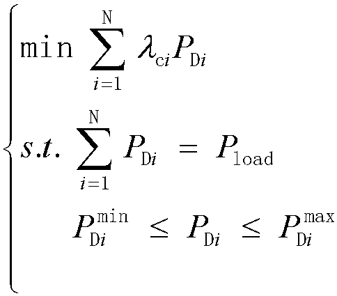
  • P D i P load P D i min ⁇ P D i ⁇ P D i max in which P D i represents a load of an individual node after participating in demand response, P load represents a total of loads of the individual node, P D i max , P D i min represent upper and lower limits of the load of the individual node after participating in demand response, and N represents the number of nodes in the system.
  • the step of processing participation in demand response based on the optimal power flow model by subjecting the loads to regional division and/or no regional division includes: when the loads are subjected to regional division, dividing the power grid system into a plurality of subregions; calculating an average carbon emission quota for each of the subregions based on the optimal power flow model; and comparing the average carbon emission quotas of respective subregions, and transferring the loads of some nodes in a subregion with a high average carbon emission quota to a subregion with a low average carbon emission quota when difference in the average carbon emission quotas of the respective subregions is greater than a preset threshold.
  • a 30-node distribution network system including on-grid wind power as shown in Fig. 5 is subjected to regional division of loads.
  • Dashed lines in Fig. 5 represent sections for regional division, that is, loads are divides into three subregions according to the dashed line markers in Fig. 5 .
  • the most significant characteristics of the regional division of loads are that, first, an optimization issue aimed at minimizing carbon emissions of loads of the entire system has been transformed into an optimization issue aimed at minimizing carbon emissions of loads of respective subregions; then, an average carbon emission quota for the loads of each subregion is calculated, and if there are significant difference among the average carbon emission quotas of respective subregions and the subregions still have the load capacity for participating in demand response, then a node of high carbon emission at a region of high carbon emission is further transferred to a node of low carbon emission at a region of low carbon emission, which is equivalent to being transformed into a dual optimization case.
  • the specific process thereof is as follows.
  • performing regional division for the loads to participate in demand response can get rid of the disadvantage that the outcome of demand response without regional division is limited by the load capacity, and further enhance the initiative of the user side to participate in system-level carbon reduction/reducing.
  • manufacturing enterprises and companies in the city such as a water supply company and that having multiple different regions to significantly reduce the total carbon emission at the user side according to the above demand response strategies, and improve effective interaction between the user side and the power supply side.
  • the steps of solving the optimal power flow model to obtain related Lagrangian multipliers in front of the power flow equations of individual nodes and defining the related Lagrangian multipliers in front of the power flow equations of individual nodes as node marginal carbon emission quotas it is further included that: under a fault condition, performing power flow calculation on the power transmission network, the power distribution network, and the microgrid based on the preset power flow equations to obtain voltage stability indicators of individual branches in the system; obtaining load reactive power of the branches, respectively, through calculation based on the optimal power flow model and the voltage stability indicators of individual branches; obtaining load reactive power of individual nodes, respectively, through calculation based on the load reactive power of the branches, and determining load active power of individual nodes, respectively, based on the load reactive power of individual nodes.
  • the user side when there are line disconnection in the power grid, generator failure at power supply side, and wind and solar power abandonment as a result of insufficient high/low voltage ride through capacity for new energy access, or even when severe power grid failure happens so that the grid disintegrates into "islands" for operation, the user side immediately switches from a mode of participating in demand response that targets at reducing carbon emissions under the normal operating condition to a demand response mode targeting at voltage stability. After the operation of the power grid stabilizes, the user side then switches back to the operating mode for carbon reduction/reducing.
  • power flow calculation i.e., the optimal power flow model
  • a voltage stability indicator L of the entire system is taken as the maximum voltage stability indicator of all branches, and the degree of voltage stability of the system can be determined based on a gap between the value L and a critical value of 1.0.
  • the power flow calculation of the "islanded" grids is completed until power errors of the virtual interconnection lines are within a predetermined error accuracy range, and real interconnection lines are added then to gradually restore the power grid to a stable state like that before the fault.
  • the loads are redistributed based on the demand response strategy targeting at voltage stability in the formula (7) by following an idea of performing regional division on the loads under a normal operation condition, so that the "islanded" grids are restored to a stable state.
  • interconnection lines are added to restore the system to the stable state before the fault.
  • the present disclosure proposes a demand response strategy of minimizing system carbon emissions in the case that the power transmission network, the power distribution network and the microgrid are all under normal operating conditions.
  • demand response strategies for the loads of the system that are subjected to regional division and no regional division, respectively, so that it is possible to further break the limitation of original demand response strategy of the system being limited by the load capacity of the system, thereby reducing the total carbon emission of the entire system.
  • the step of establishing the optimal power flow model targeting at minimizing carbon emissions at system level for the power transmission network, the power distribution network, and the microgrid includes: establishing objective functions that minimize system carbon emissions for the power transmission network, the power distribution network, and the microgrid, respectively; obtaining power flow equations corresponding to power balance of the nodes in the power transmission network, the power distribution network, and the microgrid, respectively, and applying the power flow equations corresponding to power balance of the nodes as equality-formed constraint equations for system carbon emission optimization; obtaining safety constraints for the power transmission network, the power distribution network, and the microgrid, respectively, and establishing inequality-formed constraint equations for system carbon emission optimization based on the constraints, wherein the safety constraints include active and reactive power output limits for a generator unit, voltage amplitude limit of a node, power limit of a line, and frequency limit of a system; and establishing an optimal power flow model targeting at minimizing carbon emissions at system level based on the objective functions that minimize system carbon emissions, the equality-formed constrain
  • An objective function that minimizes system carbon emissions can be established equally with respect to the power transmission network, the power distribution network, and the microgrid.
  • the power flow equations corresponding to power balance of the nodes serve as equality-formed constraints for the system carbon emission optimization, which involve active and reactive power output limits of a generator unit, voltage amplitude limit of a node, power limit of a line, frequency limit of a system, etc., and safety constraints for system operation serve as inequality-formed constraints for system carbon emission optimization. Therefore, establishing the optimal power flow model targeting at minimizing carbon emissions can be simplified as an expression involving multiple variations, multiple constraints, and nonlinear optimization as shown by the following formulas that are min f x s . t .
  • h x 0 g x ⁇ 0 in which f ( x ) represents objective functions of the system, h ( x ) represents a power flow equation of the transmission or distribution network, it also represents a power flow equation and a droop node control equation that are modified with respect to the microgrid, g ( x ) represents an inequality-formed constraint composed of the safety constraints of the system, and x represents a vector composed of a state variable and a control variables of the system.
  • Node 4 and Node 5 are connected to generators, respectively, wherein the Node 4 is called a PV node and the Node 5 is called a balance node.
  • the power transmission network system can maintain system frequency stability through the balance node, and utilize other generator units together with other balance units for system load bearing and system voltage level maintaining.
  • Node 1 is connected to the power grid, so it can also be considered that the power distribution network system can maintain system frequency stability through this balance node and further utilize other wind power generator units together with other balance units for system load bearing and system voltage level maintaining.
  • An objective function that minimizes system carbon emissions can be established equally with respect to the power transmission network, the power distribution network, and the microgrid.
  • Power flow equations corresponding to power balance of nodes serve as equality-formed constraints for system carbon emission optimization, which involve active and reactive power output limits of a generator unit, voltage amplitude limit of a node, power limit of a line, frequency limit of a system, etc., and safety constraints for system running serve as inequality-formed constraints for system carbon emission optimization. Therefore, establishment of an optimal power flow model targeting at minimizing carbon emissions can be simplified as an expression involving multiple variations, multiple constraints, and nonlinear optimization as shown by the formula (1), that are, min f x s . t .
  • h x 0 g x ⁇ 0 in which f (x) represents objective functions of the system, h ( x ) represents a power flow equation of the transmission or distribution network, it also represents a power flow equation and a droop node control equation that are modified with respect to the microgrid, g ( x ) represents inequality-formed constraints composed of constraints of the system, and x represents a vector composed of a state variable and a control variables of the system.
  • the optimal power flow model i.e., the above formula (1), targeting at minimizing carbon emissions at system level is established uniformly with respect to the power transmission network, the power distribution network, and a microgrid, and it is solved using Primal-dual interior point method.
  • a related Lagrangian multiplier in front of a power flow equation of each node can be defined as a node marginal carbon emission quota ⁇ c j , and loads may be subjected to regional division or no regional division to participate in demand response.
  • P D i P load P D i min ⁇ P D i ⁇ P D i max in which P D i represents a load of an individual node after participating in demand response, P load represents a total of loads of the individual node, P D i max , P D i min represents upper and lower limits of the load of the individual node after participating in demand response, and N represents the number of nodes in the system.
  • a 30-node distribution network system including on-grid wind power as shown in Fig. 5 is subjected to regional division of loads. That is, the loads are divides into three regions according to dashed line markers in Fig. 5 .
  • Loads participating in demand response are substituted into the optimal power flow model shown in the fomular (1) to obtain the carbon emission quotas of the loads of respective nodes after participating in demand response.
  • the user side When there are line disconnection in the power grid, generator failure at power supply side, and wind and solar power abandonment as a result of insufficient high/low voltage ride through capacity for new energy access, or even when severe power grid failure happens so that the grid disintegrates into "islands" for operation, the user side immediately switches from a mode of participating in demand response that targets at reducing carbon emissions under a normal operating condition to a demand response mode targeting at voltage stability. After the operation of the power grid is stabilized, the user side then switches back to the operating mode for carbon reduction/reducing.
  • a voltage stability indicator of the entire system is taken as the maximum voltage stability indicator L of all branches, and the degree of voltage stability of the system can be determined based on a gap between the value L and a critical value of 1.0.
  • the power flow calculation of the "islanded" grids is completed until power errors of the virtual interconnection lines are within a predetermined error accuracy range, and real interconnection lines are further added to gradually restore the power grid to a stable state like that before the fault.
  • the loads are redistributed based on the demand response strategy targeting at voltage stability in the formula (7) by following an idea of performing regional division on the loads in accordance of the normal operation condition, so that the "islanded" grids are restored to a stable state.
  • interconnection lines are added to restore the system to the stable state before the fault.
  • the present disclosure proposes a demand response strategy of minimizing system carbon emissions in the case that the power transmission network, the power distribution network and the microgrid are all under normal operating conditions.
  • demand response strategies for the loads of the system that are subjected to regional division and no regional division, respectively, so that it is possible to further break the limitation of original demand response strategy of the system being limited by load capacity of the system, thereby reducing the total carbon emission of the entire system.
  • the power source end mainly reduces carbon dioxide emissions by installing carbon capture devices, adjusting power supply structure to reduce the proportion of coal-fired power generation, and improving the efficiency of coal-fired power units; and the load end mainly achieves the goal of carbon saving and reduction in such a way that a user participates in demand response based on signals such as carbon emission intensity and marginal carbon emission.
  • the carbon reduction approaches at the power source end have limitation to some extent.
  • the cost of carbon capture devices, the renovation cost of traditional power plants, and how to improve the efficiency of coal-fired power units have become fundamental problems against carbon reduction/reducing at the power source end; while currently the mode at the load end of participating in demand response based on carbon emission signals is mainly limited by load capacity of response, which fails to achieve load balancing and significant carbon reduction and thus still cannot be widely applied in practical situations.
  • the present disclosure provides a demand response method based on node marginal carbon emissions, which is applicable to power grids such as the power transmission network, the power distribution network, and the microgrid, and further discusses in detail about implementations under normal and fault conditions of the power grid.
  • the present disclosure requires no additional hardware facility, but only reservation of sample storage space on underlying control software of the device, which is used for storage of the loads and the node marginal carbon emission signals under actual operating conditions as well as calculation of the demand response model.
  • the method is simple, safe, and reliable.
  • an apparatus for processing carbon emission demand response including: a model establishing module 210, a marginal carbon emission quota acquisition module 220, and a response processing module 230.
  • the model establishing module 210 is configured to establish an optimal power flow model targeting at minimizing carbon emissions at system level for a power transmission network, a power distribution network, and a microgrid;
  • the marginal carbon emission quota acquisition module 220 is configured to solve the optimal power flow model to obtain related Lagrangian multipliers in front of power flow equations of individual nodes, wherein a related Lagrangian multiplier in front of a power flow equation of an individual node is defined as a node marginal carbon emission quota;
  • the response processing module 230 is configured to process participation in demand response according to the optimal power flow model by subjecting loads to regional division and/or no regional division.
  • the response processing module includes a non-division processing unit for processing, in the case that the loads are subjected to no regional division, participation in demand response according to the optimal power flow model, based on the marginal carbon emission quotas of individual nodes, with the goal of minimizing carbon emissions at user side.
  • the response processing module includes: a subregion dividing unit for dividing the power grid system into a plurality of subregions in the case that the loads are subjected to regional division; a subregion carbon emission quota calculation unit for calculating average carbon emission quotas of respective subregions according to the optimal power flow model; a subregion load transfer unit for comparing the average carbon emission quotas of respective subregions, and transferring the loads of some nodes in a subregion with a high average carbon emission quota to a subregion with a low average carbon emission quota when difference in the average carbon emission quotas of the respective subregions is greater than a preset threshold.
  • the apparatus for processing carbon emission demand response further includes: a branch voltage stability indicator acquisition unit for performing, under a fault condition, power flow calculation on the power transmission network, the power distribution network, and the microgrid based on the preset power flow equations to obtain voltage stability indicators of individual branches in the system; a branch power calculation unit for calculating load reactive power of the branches based on the optimal power flow model and the voltage stability indicators of individual branches; and a node power calculation unit for calculating load reactive power of individual nodes based on the load reactive power of the branches, and determining load active power of individual nodes based on the load reactive power of individual nodes.
  • the marginal carbon emission quota acquisition module is configured to solve the optimal power flow model using Primal-dual interior point method, and obtain the related Lagrangian multipliers in front of the power flow equations of individual nodes.
  • the model establishing module includes: a minimum carbon emission objective function establishing unit for establishing objective functions that minimize system carbon emissions for the power transmission network, the power distribution networks, and the microgrid, respectively; an equality-formed constraint equation acquisition unit for obtaining power flow equations corresponding to power balance of the nodes in the power transmission network, the power distribution network, and the microgrid, respectively, and applying the power flow equations corresponding to power balance of the nodes as equality-formed constraint equations for the system carbon emission optimization; an inequality-formed constraint equation acquisition unit for obtaining safety constraints for the power transmission network, the power distribution network, and the microgrid, respectively, and establishing inequality-formed constraint equations for system carbon emission optimization based on the constraints, wherein the safety constraints include active and reactive power output limits for a generator unit, voltage amplitude limit of a node, power limit of a line, and frequency limit of a system; and a model establishing unit for establishing an optimal power flow model targeting at minimizing carbon emissions at system level based on the objective functions that minimize
  • the specific definition of the apparatus for processing carbon emission demand response can make reference to the previous definition regarding the method for processing carbon emission demand response, which will not be described any further here.
  • the various units in the above-mentioned apparatus for processing carbon emission demand response can be fully or partially implemented through software, hardware, and their combinations. These units may be embedded in or independent of, in a form of hardware, a processor in a computer device, or may be stored, in a form of software, in a memory of the computer device, for easy calling and executing corresponding operations of these units by the processor.
  • a computer device is provided. A diagram of an internal structure thereof is shown in Fig. 3 .
  • the computer device includes a processor, a memory, a network interface, a display screen, and an input device, which are connected through a system bus.
  • the processor of the computer device is configured to provide computing and control capabilities.
  • the memory of the computer device includes non-volatile storage medium and memory storage. This non-volatile storage medium stores an operating system and a computer program, and the non-volatile storage medium is equipped with a database.
  • the memory storage provides an environment for the operation of the operating system and the computer program in the non-volatile storage medium.
  • the network interface of the computer device is configured to communicate with other computer devices that have equipped with application software.
  • the computer program when being executed by the processor, implements a method for processing carbon emission demand response.
  • the display screen of the computer device may be a liquid crystal display screen or an electronic ink display screen.
  • the input device of the computer device may be a touch layer covered on the display screen, a button, trackball, or touchpad arranged on a casing of the computer device, or an external keyboard, touchpad, or mouse.
  • FIG. 3 is only a block diagram showing a portion of structures related to the technical solutions of the present disclosure, and does not constitute a limitation to the computer device applied to the solutions of the present disclosure.
  • the specific computer device can include more or fewer components than those shown in the figure, combine certain components, or have a different component arrangement.
  • a computer device including a memory and a processor, wherein the memory stores a computer program which, when being executed by the processor, implements steps of the method for processing carbon emission demand response as described above and achieves the corresponding technical outcome, which will not be described any further here.
  • a computer-readable storage medium on which a computer program is stored, wherein the computer program, when being executed by the processor, implements the steps of the method for processing carbon emission demand response as described above and achieves the corresponding technical outcome, which will not be described any further here.
  • the above-mentioned method, apparatus, computer device, and storage medium for processing carbon emission demand response are applicable to the demand response processing method of marginal carbon emissions of nodes in power transmission networks, power distribution networks, and a microgrid, and further achieve carbon saving and reduction at the end of loads in such a way that it is loads at user side to participate in demand response.
  • a demand response mode based on regional division of loads enables the loads to be further transferred from a node of high marginal carbon emission in a region of high average carbon emission to a node of low marginal carbon emission in a region of low average carbon emission by calculating average carbon emission quotas of respective regions, thereby breaking the limitation of original demand response mode being limited by load capacity, and further reducing total carbon emission at the end of loads.
  • a demand response mode based on voltage stability indicators of branches in the system to restore the system to its original normal stable operating condition, and then the demand response strategy based on node marginal carbon emissions to achieve the goal of further reducing the total carbon emission of the system.
  • Non-volatile memory may include read-only memory (ROM), programmable ROM (PROM), electrically programmable ROM (EPROM), electrically erasable programmable ROM (EEPROM), or flash memory.
  • ROM read-only memory
  • PROM programmable ROM
  • EPROM electrically programmable ROM
  • EEPROM electrically erasable programmable ROM
  • Volatile memory may include random access memory (RAM) or external cache memory.
  • RAM random access memory
  • DRAM dynamic RAM
  • SDRAM synchronous DRAM
  • DDRSDRAM dual data rate SDRAM
  • ESDRAM enhanced SDRAM
  • SLDRAM synchlink DRAM
  • RDRAM Rambus direct RAM
  • DRAM direct memory bus dynamic RAM
  • RDRAM memory bus dynamic RAM

Landscapes

  • Engineering & Computer Science (AREA)
  • Physics & Mathematics (AREA)
  • General Physics & Mathematics (AREA)
  • Business, Economics & Management (AREA)
  • Theoretical Computer Science (AREA)
  • Power Engineering (AREA)
  • Mathematical Physics (AREA)
  • Mathematical Optimization (AREA)
  • Data Mining & Analysis (AREA)
  • Pure & Applied Mathematics (AREA)
  • Economics (AREA)
  • Mathematical Analysis (AREA)
  • Computational Mathematics (AREA)
  • Human Resources & Organizations (AREA)
  • Strategic Management (AREA)
  • General Business, Economics & Management (AREA)
  • Operations Research (AREA)
  • Health & Medical Sciences (AREA)
  • General Engineering & Computer Science (AREA)
  • Software Systems (AREA)
  • Databases & Information Systems (AREA)
  • Marketing (AREA)
  • Algebra (AREA)
  • Tourism & Hospitality (AREA)
  • General Health & Medical Sciences (AREA)
  • Development Economics (AREA)
  • Quality & Reliability (AREA)
  • Entrepreneurship & Innovation (AREA)
  • Primary Health Care (AREA)
  • Game Theory and Decision Science (AREA)
  • Water Supply & Treatment (AREA)
  • Public Health (AREA)
  • Computing Systems (AREA)
  • Supply And Distribution Of Alternating Current (AREA)

Abstract

Provided in the present disclosure are a carbon emission demand response processing method, apparatus, computer device, and storage medium. The method comprises: establishing, for a power transmission network, a power distribution network, and a microgrid, an optimal power flow model targeting at minimizing carbon emissions at system level; solving the optimal power flow model to obtain related Lagrangian multipliers in front of power flow equations of individual nodes, and defining the related Lagrangian multipliers in front of the power flow equations of individual nodes as node marginal carbon emission quotas; and processing participation in demand response based on the optimal power flow model by subjecting loads to regional division and/or no regional division.

Description

    Cross-reference of related applications
  • The present application claims the benefit of the Chinese Patent Application No. CN202210088506.7, titled "Carbon emission demand response processing method, apparatus, computer device, and storage medium" filed on January 25, 2022 , the content of which is incorporated herein by reference.
  • Field of Technology
  • The present disclosure relates to the field of low-carbon application technology in power systems, and in particularly, to a carbon emission demand response processing method, apparatus, computer device, and storage medium.
  • Background
  • Recently, carbon dioxide emissions from the power industry account for more than 40% of China's total carbon dioxide emissions. As such, "carbon reduction", "carbon reducing" in power systems may be the major way to achieve carbon neutrality. At present, implementation of "carbon reduction", "carbon emission reduction" in the power industry is mainly applied on of power generation side of a power system, in which carbon dioxide emissions can be reduced by ways such as installing advanced carbon capture devices, adjusting power supply construction to reduce the proportion of coal-fired power generation, improving the efficiency of coal-fired power units, and obsoleting traditional small and medium-sized power plants with high carbon emission intensity. From the perspective of power generation side, although these above approaches can to some extent reduce carbon emissions, there is still a gap from the "carbon peaking and carbon neutrality" goals. From the perspective of a power system, therefore, carbon reduction approaches in the power industry should have not only limited to the power generation side, but also considered both transmission and consumption stages of the power system, so that the concept of carbon reduction/reducing works throughout stages of the power system, i.e., generation, transmission, distribution, and consumption. On the one hand, by using reasonable transmission planning, an entire transmission path of electricity is optimized to reduce energy loss on transmission lines, thereby achieving the effect of carbon reduction/reducing; on the other hand, loads serving as a user side actively participate in demand response with using marginal carbon emission intensity or carbon tax cost of nodes at the user side as response signals, and the loads are distributed actively and reasonably in the dimensions of time and space, thereby achieving the effect of carbon reduction/reducing.
  • Therefore, there is an urgent need for a method for processing carbon emission demand response, which achieves the goal of power system carbon reduction/reducing from the perspective of user side, and solves the problem that loads participate in the demand response based on node marginal carbon emission signals in a condition that there is a demand response model applicable on both normal and fault conditions of a power transmission network, a power distribution network, and a microgrid, etc.
  • Summary
  • Accordingly, it is necessary to provide a method, apparatus, computer device, and storage medium for processing carbon emission demand response in view of the above-mentioned technical problem.
  • A method for processing carbon emission demand response is provided, comprising: establishing an optimal power flow model targeting at minimizing carbon emissions at system level for a power transmission network, a power distribution network, and a microgrid; solving the optimal power flow model to obtain related Lagrangian multipliers in front of power flow equations of individual nodes, and defining the related Lagrangian multipliers in front of the power flow equations of individual nodes as node marginal carbon emission quotas; and processing participation in demand response based on the optimal power flow model by subjecting loads to regional division and/or no regional division.
  • An apparatus for processing carbon emission demand response is provided, comprising a model establishing module, a marginal carbon emission quota acquisition module, and a response processing module. The model establishing module is configured to establish an optimal power flow model targeting at minimizing carbon emissions at system level for a power transmission network, a power distribution network, and a microgrid; the marginal carbon emission quota acquisition module is configured to solve the optimal power flow model to obtain related Lagrangian multipliers in front of power flow equations of individual nodes, and define a related Lagrangian multiplier in front of a power flow equation of an individual node as a node marginal carbon emission quota; and the response processing module is configured to process participation in demand response according to the optimal power flow model by subjecting loads to regional division and/or no regional division.
  • A computer device is provided, comprising a memory and a processor, wherein the memory stores a computer program which, when being executed by the processor, implements the steps of the method for processing carbon emission demand response as described above.
  • A computer-readable storage medium is provided, on which a computer program is stored, wherein the computer program, when being executed by the processor, implements the steps of the method for processing carbon emission demand response as described above.
  • Brief Description of the Drawings
    • Fig. 1 is a flowchart of a method for processing carbon emission demand response according to an embodiment;
    • Fig. 2 is a block diagram of a structure of an apparatus for processing carbon emission demand response according to an embodiment;
    • Fig. 3 is a diagram showing an internal structure of a computer device according to an embodiment
    • Fig. 4Ais a diagram showing architecture of a 5-node transmission network system in a power grid system according to an embodiment;
    • Fig. 4B is a diagram showing architecture of a 30-node distribution network system including on-grid wind power according to an embodiment;
    • Fig. 4C is a diagram showing architecture of a 30-node microgrid system including power sources in a distributed pattern according to an embodiment;
    • Fig. 5 is a diagram showing architecture of a 30-node distribution network system including on-grid wind power, which is subjected to regional division, according to an embodiment.
    Detailed Description of the Embodiments
  • The specific embodiments of the present disclosure are described in detail below in conjunction with the drawings.
  • In order to make the objectives, technical solutions and advantages of this disclosure clearer, the present disclosure are described in detail below in conjunction with the drawings and the embodiments. It should be understood that the specific embodiments described herein are intended only to explain the present disclosure rather than to limit the present disclosure.
  • Embodiment 1
  • In the present embodiment, as shown in Fig. 1, provided is a method for processing carbon emission demand response, including steps 110 to 130.
  • Step 110, an optimal power flow model targeting at minimizing carbon emissions at system level is established for a power transmission network, a power distribution network, and a microgrid.
  • In the embodiment, for a power transmission network system shown in Fig. 4A, Node 4 and Node 5 are connected to generators, respectively, wherein the Node 4 is a PV node and the Node 5 is a balance node. Thus, the power transmission network system can maintain system frequency stability through the balance node, and utilize other generator units together with other balance units for system load bearing and system voltage level maintaining. For a power distribution network shown in Fig. 4B, Node 1 is connected to the power grid, so it can also be considered that the power distribution network system can maintain system frequency stability through this balance node and utilize other wind power generator units together with other balance units for system load bearing and system voltage level maintaining. For a microgrid shown in Fig. 4C, there is no balance node for the system to be connected to the major power grid, so that it is necessary to maintain the stabilities of voltage and frequency of the system by means of power sources in a distributed pattern though a specific control method. This is the most significant difference between the microgrid and the transmission and power distribution networks.
  • In this step, the optimal power flow model targeting at minimizing carbon emissions at system level is established for the power transmission network, the power distribution network, and the microgrid, wherein the optimal power flow model targeting at minimizing carbon emissions at system level is: min f x s . t . h x = 0 g x 0
    Figure imgb0001
    in which f( x ) represents objective functions of the system, h(x) represents a power flow equation of the transmission or distribution network, and it also represents a power flow equation and a droop node control equation that are modified with respect to the microgrid, g(x) represents an inequality-formed constraint composed of safety constraints of the system, and x represents a vector composed of a state variable and a control variable of the system.
  • Step 120, the optimal power flow model is solved to obtain related Lagrangian multipliers in front of power flow equations of individual nodes, and a related Lagrangian multiplier in front of a power flow equation of an individual node are defined as a node marginal carbon emission quota.
  • In one embodiment, the step of solving the optimal power flow model to obtain related Lagrangian multipliers in front of the power flow equations of individual nodes includes: solving the optimal power flow model using Primal-dual interior point method to obtain the related Lagrangian multipliers in front of the power flow equations of individual nodes.
  • In the present embodiment, under a normal operating condition, Primal-dual interior point method is used for solution-solving. The related Lagrangian multiplier in front of the power flow equation of each node can be defined as a node marginal carbon emission quota λci , and loads may be or may not be subjected to regional division to participate in demand response.
  • Step 130, participation in demand response is processed based on the optimal power flow model by subjecting the loads to regional division and/or no regional division.
  • In the embodiment, in the case that loads are subjected to regional division and in the case that the loads are subjected to no regional division, different methods are used to process participation in demand response.
  • In the above embodiments, the method for processing demand response based on node marginal carbon emissions, which is applicable equally to a power transmission network, a power distribution network and a microgrid and is implemented in such a way that it is loads at user side to participate in demand response, thereby achieving further carbon saving and reduction at an end of loads.
  • In one embodiment, the step of processing participation in demand response based on the optimal power flow model by subjecting the loads to regional division and/or no regional division includes: when the loads are subjected to no regional division, processing participation in demand response according to the optimal power flow model, based on respective node marginal carbon emission quotas, with minimization of carbon emissions at user side as a goal of demand response.
  • In this embodiment, in the case that the loads are subjected to no regional division, a load of an individual node participates in demand response by using a load at a predetermined proportion k in terms of its own load condition. The following formula can be obtained based on this optimal power flow model according to respective node marginal carbon emission quotas λci , with minimization of carbon emissions at user side as a goal of demand response: min i = 1 N λ c i P D i s . t . i = 1 N P D i = P load P D i min P D i P D i max
    Figure imgb0002
    in which P Di represents a load of an individual node after participating in demand response, P load represents a total of loads of the individual node, P D i max , P D i min
    Figure imgb0003
    represent upper and lower limits of the load of the individual node after participating in demand response, and N represents the number of nodes in the system. Using the method for processing demand response as illustrated by the above formula, it is possible to transfer loads of a node of high carbon emission in the entire system to loads of a node of low carbon emission, and process participation in demand response with minimization of carbon emissions of the entire system as an ultimate goal.
  • In one embodiment, the step of processing participation in demand response based on the optimal power flow model by subjecting the loads to regional division and/or no regional division includes: when the loads are subjected to regional division, dividing the power grid system into a plurality of subregions; calculating an average carbon emission quota for each of the subregions based on the optimal power flow model; and comparing the average carbon emission quotas of respective subregions, and transferring the loads of some nodes in a subregion with a high average carbon emission quota to a subregion with a low average carbon emission quota when difference in the average carbon emission quotas of the respective subregions is greater than a preset threshold.
  • It should be understood that in the case that the loads are subjected to no regional division, due to limitation of load capacity of demand response, it is impossible to transfer all loads of the node of high carbon emission to the node of low carbon emission, so that advantages of the above demand response strategy cannot be fully leveraged. Therefore, in order to avoid the above problem, in the present embodiment, a 30-node distribution network system including on-grid wind power as shown in Fig. 5 is subjected to regional division of loads. Dashed lines in Fig. 5 represent sections for regional division, that is, loads are divides into three subregions according to the dashed line markers in Fig. 5. The most significant characteristics of the regional division of loads are that, first, an optimization issue aimed at minimizing carbon emissions of loads of the entire system has been transformed into an optimization issue aimed at minimizing carbon emissions of loads of respective subregions; then, an average carbon emission quota for the loads of each subregion is calculated, and if there are significant difference among the average carbon emission quotas of respective subregions and the subregions still have the load capacity for participating in demand response, then a node of high carbon emission at a region of high carbon emission is further transferred to a node of low carbon emission at a region of low carbon emission, which is equivalent to being transformed into a dual optimization case. The specific process thereof is as follows.
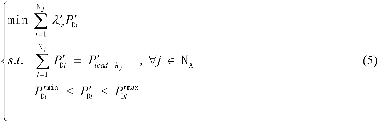
  • Firstly, with respect to subregions jN A , demand response is carried out for each of the subregions to obtain: min i = 1 N j λ c i P D i s . t . i = 1 N j P D i = P load A j , j N A P D i min P D i P D i max
    Figure imgb0004
    in which NA represents a set of load subregions and N j represents the number of load nodes in the jth subregion. Loads participating in demand response are substituted into the optimal power flow model as shown in the fomular (1) to obtain the carbon emission quotas of the loads of respective nodes after participating in demand response. The average carbon emission quotas λ cj of respective regions are calculated according to the formula, that is λ ¯ c j = i = 1 N j λ cj P D i i = 1 N j P D i , j N A
    Figure imgb0005
  • Then, differences ç between the average carbon emission quotas λ cj of respective regions are compared, respectively. If a difference ç is greater than a set threshold value σ, it is considered proceeding to a second level of demand response for the loads. That is, within a range of load capacity for participation in demand response, it is considered transferring loads of some nodes of high marginal carbon emission from a region with high average carbon emission quota to a region with low average carbon emission quota, that is, this region with low average carbon emission quota adds, on the basis of its original load, some further loads ΔPload-EX-Aj transferred from some regions, and it is obtained that P load A j = P load A j + ΔP load EX A j
    Figure imgb0006
    . min i = 1 N j λ c i P D i s . t . i = 1 N j P D i = P load A j , j N A P D i min P D i P D i max
    Figure imgb0007
  • As mentioned above, performing regional division for the loads to participate in demand response can get rid of the disadvantage that the outcome of demand response without regional division is limited by the load capacity, and further enhance the initiative of the user side to participate in system-level carbon reduction/reducing. From the perspective of practical application, it is possible for manufacturing enterprises and companies in the city, such as a water supply company and that having multiple different regions to significantly reduce the total carbon emission at the user side according to the above demand response strategies, and improve effective interaction between the user side and the power supply side.
  • In one embodiment, after the steps of solving the optimal power flow model to obtain related Lagrangian multipliers in front of the power flow equations of individual nodes and defining the related Lagrangian multipliers in front of the power flow equations of individual nodes as node marginal carbon emission quotas, it is further included that: under a fault condition, performing power flow calculation on the power transmission network, the power distribution network, and the microgrid based on the preset power flow equations to obtain voltage stability indicators of individual branches in the system; obtaining load reactive power of the branches, respectively, through calculation based on the optimal power flow model and the voltage stability indicators of individual branches; obtaining load reactive power of individual nodes, respectively, through calculation based on the load reactive power of the branches, and determining load active power of individual nodes, respectively, based on the load reactive power of individual nodes.
  • In this embodiment, when there are line disconnection in the power grid, generator failure at power supply side, and wind and solar power abandonment as a result of insufficient high/low voltage ride through capacity for new energy access, or even when severe power grid failure happens so that the grid disintegrates into "islands" for operation, the user side immediately switches from a mode of participating in demand response that targets at reducing carbon emissions under the normal operating condition to a demand response mode targeting at voltage stability. After the operation of the power grid stabilizes, the user side then switches back to the operating mode for carbon reduction/reducing.
  • Therefore, under the fault condition, power flow calculation (i.e., the optimal power flow model) should be carried out equally on the power transmission network, the power distribution network, or the microgrid. If the power grid does not suffer from disintegration under the fault condition, the corresponding power flow equations can be solved using the Newton-Raphson method or the improved Levenberg-Marquardt method and the voltage stability indicators of individual branches are calculated, that is, L i = 4 XP j RQ j 2 + XQ j + RP j
    Figure imgb0008
    in which Pi, Qi represent active power and reactive power of a node i at intermediate segment of a line, Pj, Qj represent active power and reactive power of a node j at the end of the line, and A, X represent the resistance and the reactance between a line i-j. Therefore, a voltage stability indicator L of the entire system is taken as the maximum voltage stability indicator of all branches, and the degree of voltage stability of the system can be determined based on a gap between the value L and a critical value of 1.0. According to the formula below, a model for the loads to participate in demand response under the fault condition based on the voltage stability indicators Li of the branches is that min i = 1 N L i Q BL i s . t . i = 1 N Q BL i = Q load Q BL i min Q BL i Q BL i max
    Figure imgb0009
    in which Q BLi is reactive power of loads on the ith branch, Q load is total reactive power of loads of all branches in the system, and Q BL i max , Q BL i min
    Figure imgb0010
    are upper and lower limits of the reactive power of loads on the ith branch. After allocation of the reactive power of loads on the branches is determined, the reactive power of loads at individual nodes are determined by calculation. Assuming that the loads of an individual node employ a constant power factor, upon determination of the reactive power of loads of the node, the active power of loads of the node can be determined. After the system fault is eliminated and the system is stabilized, the system then operates in the demand response mode targeting at minimizing carbon emissions at system level.
  • Under fault conditions, if a serious fault occurs and causes the power grid to operate as "islands", in order to avoid the situation where Jacobian matrix of the power flow equation of an "islanded" grid is singular so that the Newton method fails to converge or has no solution, the improved Levenberg-Marquardt method can be used to obtain the least squares solution, thereby providing information for subsequent power flow adjustment and improvement. After the power flow calculation of the "islanded" grids is completed, appropriate adjustments are made to ensure the stable operation of the "islanded" grids. First is to carry out power flow calculation for the major power grid through virtual interconnection lines among the "islanded" grids by following an idea of performing alternating iteration of power flow. The power flow calculation of the "islanded" grids is completed until power errors of the virtual interconnection lines are within a predetermined error accuracy range, and real interconnection lines are added then to gradually restore the power grid to a stable state like that before the fault. Secondly, after the power flow calculation of the "islanded" microgrid is completed, the loads are redistributed based on the demand response strategy targeting at voltage stability in the formula (7) by following an idea of performing regional division on the loads under a normal operation condition, so that the "islanded" grids are restored to a stable state. Then, through the alternating iteration algorithm of power flow, interconnection lines are added to restore the system to the stable state before the fault. When the fault condition reaches a normal stable operating state by adding the interconnection lines and redistributing the loads, the system then carries out the demand response mode targeting at minimizing carbon emissions at system level.
  • In summary, the present disclosure proposes a demand response strategy of minimizing system carbon emissions in the case that the power transmission network, the power distribution network and the microgrid are all under normal operating conditions. In this case, according to differences in system construction, it is discussed about demand response strategies for the loads of the system that are subjected to regional division and no regional division, respectively, so that it is possible to further break the limitation of original demand response strategy of the system being limited by the load capacity of the system, thereby reducing the total carbon emission of the entire system. Turning to a mode regarding fault, firstly, it is discussed about the power flow calculation method for restoring from a "fault" operating mode to a "normal" operating mode, then it is proposed a demand response strategy targeting at system voltage stability, and finally, when the major system has operated stably, a demand response mode targeting at carbon reduction/reducing under the normal operating condition, thereby further reducing the total carbon emission of the entire major system.
  • In one embodiment, the step of establishing the optimal power flow model targeting at minimizing carbon emissions at system level for the power transmission network, the power distribution network, and the microgrid includes: establishing objective functions that minimize system carbon emissions for the power transmission network, the power distribution network, and the microgrid, respectively; obtaining power flow equations corresponding to power balance of the nodes in the power transmission network, the power distribution network, and the microgrid, respectively, and applying the power flow equations corresponding to power balance of the nodes as equality-formed constraint equations for system carbon emission optimization; obtaining safety constraints for the power transmission network, the power distribution network, and the microgrid, respectively, and establishing inequality-formed constraint equations for system carbon emission optimization based on the constraints, wherein the safety constraints include active and reactive power output limits for a generator unit, voltage amplitude limit of a node, power limit of a line, and frequency limit of a system; and establishing an optimal power flow model targeting at minimizing carbon emissions at system level based on the objective functions that minimize system carbon emissions, the equality-formed constraint equations, and the inequality-formed constraint equations.
  • An objective function that minimizes system carbon emissions can be established equally with respect to the power transmission network, the power distribution network, and the microgrid. The power flow equations corresponding to power balance of the nodes serve as equality-formed constraints for the system carbon emission optimization, which involve active and reactive power output limits of a generator unit, voltage amplitude limit of a node, power limit of a line, frequency limit of a system, etc., and safety constraints for system operation serve as inequality-formed constraints for system carbon emission optimization. Therefore, establishing the optimal power flow model targeting at minimizing carbon emissions can be simplified as an expression involving multiple variations, multiple constraints, and nonlinear optimization as shown by the following formulas that are min f x s . t . h x = 0 g x 0
    Figure imgb0011
    in which f(x) represents objective functions of the system, h ( x ) represents a power flow equation of the transmission or distribution network, it also represents a power flow equation and a droop node control equation that are modified with respect to the microgrid, g(x) represents an inequality-formed constraint composed of the safety constraints of the system, and x represents a vector composed of a state variable and a control variables of the system.
  • Embodiment 2
  • Firstly, for a power transmission network system shown in Fig. 4A, Node 4 and Node 5 are connected to generators, respectively, wherein the Node 4 is called a PV node and the Node 5 is called a balance node. Thus, the power transmission network system can maintain system frequency stability through the balance node, and utilize other generator units together with other balance units for system load bearing and system voltage level maintaining. For a power distribution network shown in Fig. 4B, Node 1 is connected to the power grid, so it can also be considered that the power distribution network system can maintain system frequency stability through this balance node and further utilize other wind power generator units together with other balance units for system load bearing and system voltage level maintaining. For a microgrid shown in Fig. 4C, there is no balance node for the system to be connected to the major power grid, so that it is necessary to maintain the stabilities of voltage and frequency of the system by means of power sources in a distributed pattern though a specific control method. This is the most significant difference between the microgrid and the transmission and power distribution networks.
  • An objective function that minimizes system carbon emissions can be established equally with respect to the power transmission network, the power distribution network, and the microgrid. Power flow equations corresponding to power balance of nodes serve as equality-formed constraints for system carbon emission optimization, which involve active and reactive power output limits of a generator unit, voltage amplitude limit of a node, power limit of a line, frequency limit of a system, etc., and safety constraints for system running serve as inequality-formed constraints for system carbon emission optimization. Therefore, establishment of an optimal power flow model targeting at minimizing carbon emissions can be simplified as an expression involving multiple variations, multiple constraints, and nonlinear optimization as shown by the formula (1), that are, min f x s . t . h x = 0 g x 0
    Figure imgb0012
    in which f(x) represents objective functions of the system, h(x) represents a power flow equation of the transmission or distribution network, it also represents a power flow equation and a droop node control equation that are modified with respect to the microgrid, g(x) represents inequality-formed constraints composed of constraints of the system, and x represents a vector composed of a state variable and a control variables of the system.
  • Demand response method under normal operating condition
  • The optimal power flow model, i.e., the above formula (1), targeting at minimizing carbon emissions at system level is established uniformly with respect to the power transmission network, the power distribution network, and a microgrid, and it is solved using Primal-dual interior point method. A related Lagrangian multiplier in front of a power flow equation of each node can be defined as a node marginal carbon emission quota λcj , and loads may be subjected to regional division or no regional division to participate in demand response.
  • A. Loads subjected to no regional division
  • According to condition of a load of an individual node, assuming that the load participates in demand response by using a load at a predetermined proportion k of its own load, and obtained according to respective node marginal carbon emission quotas λcj , with minimization of carbon emissions at user side as a goal of demand response, is that min i = 1 N λ c i P D i s . t . i = 1 N P D i = P load P D i min P D i P D i max
    Figure imgb0013
    in which P Di represents a load of an individual node after participating in demand response, P load represents a total of loads of the individual node, P D i max , P D i min
    Figure imgb0014
    represents upper and lower limits of the load of the individual node after participating in demand response, and N represents the number of nodes in the system. Using the method for processing demand response as illustrated by the above formula (2), it is possible to transfer loads of nodes of high carbon emission in the entire system to loads of nodes of low carbon emission, with minimization of carbon emissions of the entire system as an ultimate goal. However, this demand response strategy is to some extent limited by load capacity for participating in demand response as well as on-grid capacity of new energy.
  • B. Loads subjected to regional division
  • The above-mentioned loads are subjected to no regional division, so that it is impossible to transfer all loads of the nodes of high carbon emission to the nodes of low carbon emission due to limitation of the load capacity for participating in demand response, so that advantages of the above demand response strategy cannot be fully leveraged. Therefore, in order to avoid the above problem, a 30-node distribution network system including on-grid wind power as shown in Fig. 5 is subjected to regional division of loads. That is, the loads are divides into three regions according to dashed line markers in Fig. 5. The most significant characteristics of regional division of loads are that, first, an optimization issue aimed at minimizing carbon emissions of the loads of the entire system has been transformed into an optimization issue aimed at minimizing carbon emissions of loads of respective regions; then, an average carbon emission quota for the loads of each region is calculated, and if there are significant difference among the average carbon emission quotas of respective regions and the regions still have the load capacity for participating in demand response, then a node of high carbon emission at a region of high carbon emission is further transferred to a node of low carbon emission at a region of low carbon emission, which is equivalent to being transformed into a dual optimization case.
  • Firstly, with respect to divided regions jN A, demand response is carried out for each of the subregions, that is min i = 1 N j λ c i P D i s . t . i = 1 N j P D i = P load A j , j N A P D i min P D i P D i max
    Figure imgb0015
    in which NA represents a set of load subregions and N j represents the number of load nodes in the jth subregion. Loads participating in demand response are substituted into the optimal power flow model shown in the fomular (1) to obtain the carbon emission quotas of the loads of respective nodes after participating in demand response. The average carbon emission quotas λ cj of respective regions are calculated according to the following formula (4), that is λ ¯ c j = i = 1 N j λ cj P D i i = 1 N j P D i , j N A
    Figure imgb0016
  • Then, differences ç between the average carbon emission quotas λ cj of respective regions are compared, respectively. If a difference ç is greater than a set threshold value σ, it is considered proceeding to a second level of demand response for the loads. That is, within a range of load capacity for participation in demand response, it is considered transferring loads of some nodes of high marginal carbon emission from a region with high average carbon emission quota to a region with low average carbon emission quota, that is, this region with low average carbon emission quota adds, on the basis of its original load, some further loads ΔP load-EX-Aj transferred from some regions, and it is obtained that P load A j = P load A j + ΔP load EX A j .
    Figure imgb0017
    . min i = 1 N j λ c i P D i s . t . i = 1 N j P D i = P load A j , j N A P D i min P D i P D i max
    Figure imgb0018
  • As mentioned above, performing regional division for the loads to participate in demand response can get rid of the disadvantage that the outcome of demand response without regional division is limited by the load capacity, and further enhance the initiative of the user side to participate in system-level carbon reduction/reducing. From the perspective of practical application, it is possible for manufacturing enterprises and companies in the city, such as a water supply company and the one having multiple different regions to significantly reduce the total carbon emission at the user side according to the above demand response strategies and improve effective interaction between the user side and the power supply side.
  • Demand response strategy under fault condition
  • When there are line disconnection in the power grid, generator failure at power supply side, and wind and solar power abandonment as a result of insufficient high/low voltage ride through capacity for new energy access, or even when severe power grid failure happens so that the grid disintegrates into "islands" for operation, the user side immediately switches from a mode of participating in demand response that targets at reducing carbon emissions under a normal operating condition to a demand response mode targeting at voltage stability. After the operation of the power grid is stabilized, the user side then switches back to the operating mode for carbon reduction/reducing.
  • Therefore, under the fault condition, power flow calculation (i.e., the formula (1) should be carried out equally on the power transmission network, the power distribution network, or the microgrid under investigation. If the power grid does not suffer from disintegration under the fault condition, the corresponding power flow equations can be solved using the Newton-Raphson method or the improved Levenberg-Marquardt method, and the voltage stability indicators of individual branches are calculated, that is, L i = 4 XP j RQ j 2 + XQ j + RP j
    Figure imgb0019
    in which Pi, Qi represent active power and reactive power of a node i at intermediate segment of a line, Pj, Qj represent active power and reactive power of a node j at the end of the line, and R, X represent the resistance and the reactance between a line i-j. Therefore, a voltage stability indicator of the entire system is taken as the maximum voltage stability indicator L of all branches, and the degree of voltage stability of the system can be determined based on a gap between the value L and a critical value of 1.0. According to the formula (7) below, a model for the loads to participate in demand response under the fault condition based on the voltage stability indicators Li of the branches is that min i = 1 N L i Q BL i s . t . i = 1 N Q BL i = Q load Q BL i min Q BL i Q BL i max
    Figure imgb0020
    in which Q BLi is reactive power of loads on the ith branch, Q load is total reactive power of loads of all branches in the system, and Q BL i max , Q BL i min
    Figure imgb0021
    are upper and lower limits of the reactive power of loads on the ith branch. After allocation of the reactive power of loads on the branches is determined, the reactive power of loads at individual nodes are determined by calculation. Assuming that the loads of an individual node employ a constant power factor, upon determination of the reactive power of loads of the node, the active power of loads of the node can be determined. After the system fault is eliminated and the system is stabilized, the system then operates in the demand response mode targeting at minimizing carbon emissions at system level.
  • Under fault conditions, if a serious fault occurs and causes the power grid to operate as "islands", in order to avoid the situation where Jacobian matrix of the power flow equation of an "islanded" grid is singular so that the Newton method fails to converge or has no solution, the improved Levenberg-Marquardt method can be used to obtain the least squares solution, thereby providing information for subsequent power flow adjustment and improvement. After the power flow calculation of the "islanded" grids is completed, appropriate adjustments are made to ensure the stable operation of the "islanded" grids. First is to carry out power flow calculation for the major power grid through virtual interconnection lines among the "islanded" grids by following an idea of performing alternating iteration of power flow. The power flow calculation of the "islanded" grids is completed until power errors of the virtual interconnection lines are within a predetermined error accuracy range, and real interconnection lines are further added to gradually restore the power grid to a stable state like that before the fault. Secondly, after the power flow calculation of the "islanded" microgrid is completed, the loads are redistributed based on the demand response strategy targeting at voltage stability in the formula (7) by following an idea of performing regional division on the loads in accordance of the normal operation condition, so that the "islanded" grids are restored to a stable state. Then, through the alternating iteration algorithm of power flow, interconnection lines are added to restore the system to the stable state before the fault. When the fault condition reaches a normal stable operating state by adding the interconnection lines and redistributing the loads, the system then carries out the demand response mode targeting at minimizing carbon emissions at system level.
  • In summary, the present disclosure proposes a demand response strategy of minimizing system carbon emissions in the case that the power transmission network, the power distribution network and the microgrid are all under normal operating conditions. In this case, according to differences in system construction, it is discussed about demand response strategies for the loads of the system that are subjected to regional division and no regional division, respectively, so that it is possible to further break the limitation of original demand response strategy of the system being limited by load capacity of the system, thereby reducing the total carbon emission of the entire system. Turning to a mode regarding fault, firstly, it is discussed about the power flow calculation method for restoring from a "fault" operating mode to a "normal" operating mode, then it is proposed a demand response strategy targeting at system voltage stability, and finally, when the major system has operated stably, a demand response mode targeting at carbon reduction/reducing under the normal operating condition, thereby further reducing the total carbon emission of the entire major system.
  • The beneficial effects of the present disclosure are as follows.
    • 1. It is innovatively proposed a demand response method based on node marginal carbon emissions, which is applicable to a power transmission network, a power distribution network, a microgrid, etc. and is implemented in such a way that it is loads at user side to participate in demand response, thereby achieving further carbon saving and reduction at the end of loads.
    • 2, In the case of normal operating condition, it is proposed for the first time a demand response mode based on regional division of loads. By calculating average carbon emission quotas of respective regions, it is possible that the loads are further transferred from a node of high marginal carbon emission in a region of high average carbon emission to a node of low marginal carbon emission in a region of low average carbon emission, thereby breaking the limitation of original demand response mode being limited by load capacity, and further reducing total carbon emission at an end of loads.
    • 3. In the case of fault operating conditions, it is adopted a demand response mode based on voltage stability indicators of branches in the system to restore the system to its original normal stable operating condition, then it is adopted the demand response strategy based on node marginal carbon emissions to achieve the goal of further reducing the total carbon emission of the system.
  • At present, researches on carbon reduction/reducing in the power industry mainly focus on power source end and load end. The power source end mainly reduces carbon dioxide emissions by installing carbon capture devices, adjusting power supply structure to reduce the proportion of coal-fired power generation, and improving the efficiency of coal-fired power units; and the load end mainly achieves the goal of carbon saving and reduction in such a way that a user participates in demand response based on signals such as carbon emission intensity and marginal carbon emission. However, the carbon reduction approaches at the power source end have limitation to some extent. Firstly, the cost of carbon capture devices, the renovation cost of traditional power plants, and how to improve the efficiency of coal-fired power units have become fundamental problems against carbon reduction/reducing at the power source end; while currently the mode at the load end of participating in demand response based on carbon emission signals is mainly limited by load capacity of response, which fails to achieve load balancing and significant carbon reduction and thus still cannot be widely applied in practical situations. The present disclosure provides a demand response method based on node marginal carbon emissions, which is applicable to power grids such as the power transmission network, the power distribution network, and the microgrid, and further discusses in detail about implementations under normal and fault conditions of the power grid. Under the normal operating condition, an innovative mode regarding regional division of loads for participating in demand response has been proposed for the first time, which solves the problem that loads for participating in demand response are limited by a capacity limit so that the loads are allowed to participate in demand response to the maximum extent, thereby achieving the goal of reducing carbon emissions at system level. Under the fault conditions, voltage stability indicators of branches are used as a demand response signal to quickly transition the system from a fault condition to the normal stable condition, then the demand response strategy based on node marginal carbon emissions is adopted, thereby achieving the effect of carbon reduction/reducing in the entire system. The present disclosure requires no additional hardware facility, but only reservation of sample storage space on underlying control software of the device, which is used for storage of the loads and the node marginal carbon emission signals under actual operating conditions as well as calculation of the demand response model. The method is simple, safe, and reliable.
  • Embodiment 3
  • In the present embodiment, as shown in Fig. 2, provided is an apparatus for processing carbon emission demand response, including: a model establishing module 210, a marginal carbon emission quota acquisition module 220, and a response processing module 230.
  • The model establishing module 210 is configured to establish an optimal power flow model targeting at minimizing carbon emissions at system level for a power transmission network, a power distribution network, and a microgrid; the marginal carbon emission quota acquisition module 220 is configured to solve the optimal power flow model to obtain related Lagrangian multipliers in front of power flow equations of individual nodes, wherein a related Lagrangian multiplier in front of a power flow equation of an individual node is defined as a node marginal carbon emission quota; and the response processing module 230 is configured to process participation in demand response according to the optimal power flow model by subjecting loads to regional division and/or no regional division.
  • In one embodiment, the response processing module includes a non-division processing unit for processing, in the case that the loads are subjected to no regional division, participation in demand response according to the optimal power flow model, based on the marginal carbon emission quotas of individual nodes, with the goal of minimizing carbon emissions at user side.
  • In one embodiment, the response processing module includes: a subregion dividing unit for dividing the power grid system into a plurality of subregions in the case that the loads are subjected to regional division; a subregion carbon emission quota calculation unit for calculating average carbon emission quotas of respective subregions according to the optimal power flow model; a subregion load transfer unit for comparing the average carbon emission quotas of respective subregions, and transferring the loads of some nodes in a subregion with a high average carbon emission quota to a subregion with a low average carbon emission quota when difference in the average carbon emission quotas of the respective subregions is greater than a preset threshold.
  • In one embodiment, the apparatus for processing carbon emission demand response further includes: a branch voltage stability indicator acquisition unit for performing, under a fault condition, power flow calculation on the power transmission network, the power distribution network, and the microgrid based on the preset power flow equations to obtain voltage stability indicators of individual branches in the system; a branch power calculation unit for calculating load reactive power of the branches based on the optimal power flow model and the voltage stability indicators of individual branches; and a node power calculation unit for calculating load reactive power of individual nodes based on the load reactive power of the branches, and determining load active power of individual nodes based on the load reactive power of individual nodes.
  • In one embodiment, the marginal carbon emission quota acquisition module is configured to solve the optimal power flow model using Primal-dual interior point method, and obtain the related Lagrangian multipliers in front of the power flow equations of individual nodes.
  • In one embodiment, the model establishing module includes: a minimum carbon emission objective function establishing unit for establishing objective functions that minimize system carbon emissions for the power transmission network, the power distribution networks, and the microgrid, respectively; an equality-formed constraint equation acquisition unit for obtaining power flow equations corresponding to power balance of the nodes in the power transmission network, the power distribution network, and the microgrid, respectively, and applying the power flow equations corresponding to power balance of the nodes as equality-formed constraint equations for the system carbon emission optimization; an inequality-formed constraint equation acquisition unit for obtaining safety constraints for the power transmission network, the power distribution network, and the microgrid, respectively, and establishing inequality-formed constraint equations for system carbon emission optimization based on the constraints, wherein the safety constraints include active and reactive power output limits for a generator unit, voltage amplitude limit of a node, power limit of a line, and frequency limit of a system; and a model establishing unit for establishing an optimal power flow model targeting at minimizing carbon emissions at system level based on the objective functions that minimize system carbon emissions, the equality-formed constraint equations, and the inequality-formed constraint equations.
  • In one embodiment, the optimal power flow model with the goal of minimizing carbon emissions at system level is: min f x s . t . h x = 0 g x 0
    Figure imgb0022
    in which, f( x ) represents objective functions of the system, h(x) represents a power flow equation of the transmission or distribution network, it also represents a power flow equation and a droop node control equation that are modified with respect to the microgrid, g ( x ) represents an inequality-formed constraint composed of the safety constraints of the system, and x represents a vector composed of a state variable and a control variables of the system.
  • The specific definition of the apparatus for processing carbon emission demand response can make reference to the previous definition regarding the method for processing carbon emission demand response, which will not be described any further here. The various units in the above-mentioned apparatus for processing carbon emission demand response can be fully or partially implemented through software, hardware, and their combinations. These units may be embedded in or independent of, in a form of hardware, a processor in a computer device, or may be stored, in a form of software, in a memory of the computer device, for easy calling and executing corresponding operations of these units by the processor.
  • Embodiment 4
  • In the present embodiment, a computer device is provided. A diagram of an internal structure thereof is shown in Fig. 3. The computer device includes a processor, a memory, a network interface, a display screen, and an input device, which are connected through a system bus. In this case, the processor of the computer device is configured to provide computing and control capabilities. The memory of the computer device includes non-volatile storage medium and memory storage. This non-volatile storage medium stores an operating system and a computer program, and the non-volatile storage medium is equipped with a database. The memory storage provides an environment for the operation of the operating system and the computer program in the non-volatile storage medium. The network interface of the computer device is configured to communicate with other computer devices that have equipped with application software. The computer program, when being executed by the processor, implements a method for processing carbon emission demand response. The display screen of the computer device may be a liquid crystal display screen or an electronic ink display screen. The input device of the computer device may be a touch layer covered on the display screen, a button, trackball, or touchpad arranged on a casing of the computer device, or an external keyboard, touchpad, or mouse.
  • It can be can understand by a person skilled in the art that the structure shown in Fig. 3 is only a block diagram showing a portion of structures related to the technical solutions of the present disclosure, and does not constitute a limitation to the computer device applied to the solutions of the present disclosure. The specific computer device can include more or fewer components than those shown in the figure, combine certain components, or have a different component arrangement.
  • In one embodiment, a computer device is provided, including a memory and a processor, wherein the memory stores a computer program which, when being executed by the processor, implements steps of the method for processing carbon emission demand response as described above and achieves the corresponding technical outcome, which will not be described any further here.
  • Embodiment 5
  • In the present embodiment, a computer-readable storage medium is provided, on which a computer program is stored, wherein the computer program, when being executed by the processor, implements the steps of the method for processing carbon emission demand response as described above and achieves the corresponding technical outcome, which will not be described any further here.
  • The above-mentioned method, apparatus, computer device, and storage medium for processing carbon emission demand response are applicable to the demand response processing method of marginal carbon emissions of nodes in power transmission networks, power distribution networks, and a microgrid, and further achieve carbon saving and reduction at the end of loads in such a way that it is loads at user side to participate in demand response.
  • In addition, in the embodiment, in the case of normal operating condition, a demand response mode based on regional division of loads enables the loads to be further transferred from a node of high marginal carbon emission in a region of high average carbon emission to a node of low marginal carbon emission in a region of low average carbon emission by calculating average carbon emission quotas of respective regions, thereby breaking the limitation of original demand response mode being limited by load capacity, and further reducing total carbon emission at the end of loads.
  • In addition, in the embodiment, in the case of fault operating conditions, it is adopted, firstly, a demand response mode based on voltage stability indicators of branches in the system to restore the system to its original normal stable operating condition, and then the demand response strategy based on node marginal carbon emissions to achieve the goal of further reducing the total carbon emission of the system.
  • It can be understood by a person of ordinary skill in the art that implementation of all or part of processes in the method according to these above embodiments can be accomplished by instructing relevant hardware through a computer program. The computer program can be stored in a non-volatile computer-readable storage medium, and the computer program, when being executed, can include the processes in the embodiments of the above method. In this case, any reference to memory, storage, database, or other medium adopted in the various embodiments provided by the present disclosure can each include non-volatile and/or volatile memory. Non-volatile memory may include read-only memory (ROM), programmable ROM (PROM), electrically programmable ROM (EPROM), electrically erasable programmable ROM (EEPROM), or flash memory. Volatile memory may include random access memory (RAM) or external cache memory. As an explanation rather than limitation, RAM is available in various forms, such as static RAM (SRAM), dynamic RAM (DRAM), synchronous DRAM (SDRAM), dual data rate SDRAM (DDRSDRAM), enhanced SDRAM (ESDRAM), synchlink DRAM (SLDRAM), Rambus direct RAM (RDRAM), direct memory bus dynamic RAM (DRDRAM), and memory bus dynamic RAM (RDRAM).
  • The various technical features of the above embodiments can be combined arbitrarily. To make the description concise, all possible combinations of the various technical features in the above embodiments have not been described exhaustively. However, a combination of these technical features should be considered within the scope of the present disclosure as long as there is no conflict therein.
  • The above embodiments illustrate only several implementations of the present disclosure with a manner of description of more specific and detailed, which, however, should not be understood as a limitation on the scope of the present disclosure. It should be noted for the person of ordinary skill in the art that several modifications and improvements can be made without departing from the proposals of the present disclosure, all of which fall within the scope of protection of the present disclosure. Therefore, the scope of protection of the present disclosure shall be based on the attached claims.

Claims (10)

  1. A method for processing carbon emission demand response, comprising:
    establishing an optimal power flow model targeting at minimizing carbon emissions at system level for a power transmission network, a power distribution network, and a microgrid;
    solving the optimal power flow model to obtain related Lagrangian multipliers in front of power flow equations of individual nodes, and defining a related Lagrangian multiplier in front of a power flow equation of an individual node as a node marginal carbon emission quota; and
    processing participation in demand response based on the optimal power flow model by subjecting loads to regional division and/or no regional division.
  2. The method according to claim 1, characterized in that processing participation in demand response based on the optimal power flow model by subjecting loads to regional division and/or no regional division comprises:
    processing, when the loads are subjected to no regional division, participation in demand response according to the optimal power flow model, based on respective node marginal carbon emission quotas, with minimization of carbon emissions at user side as a goal of demand response.
  3. The method according to claim 1, characterized in that the method of processing participation in demand response based on the optimal power flow model by subjecting loads to regional division and/or no regional division comprises:
    dividing, when the loads are subjected to regional division, power grid system into a plurality of subregions;
    calculating average carbon emission quotas for respective subregions based on the optimal power flow model; and
    comparing the average carbon emission quotas of respective subregions, and transferring the loads of some nodes in a subregion with a high average carbon emission quota to a subregion with a low average carbon emission quota when difference in the average carbon emission quotas of the respective subregions is greater than a preset threshold.
  4. The method according to claim 1, characterized in that after solving the optimal power flow model to obtain related Lagrangian multipliers in front of the power flow equations of individual nodes and defining the related Lagrangian multipliers in front of the power flow equations of individual nodes as node marginal carbon emission quotas, the method further comprises:
    performing, under a fault condition, power flow calculation on the power transmission network, the power distribution network, and the microgrid based on the preset power flow equations to obtain voltage stability indicators of individual branches in power grid system;
    obtaining load reactive power of the branches, respectively, by calculation based on the optimal power flow model and the voltage stability indicators of individual branches;
    obtaining load reactive power of individual nodes, respectively, by calculation based on the load reactive power of the branches, and determining load active power of individual nodes, respectively, based on the load reactive power of individual nodes.
  5. The method according to claim 1, characterized in that solving the optimal power flow model to obtain related Lagrangian multipliers in front of the power flow equations of individual nodes comprises:
    solving the optimal power flow model by using Primal-dual interior point method to obtain the related Lagrangian multipliers in front of the power flow equations of individual nodes.
  6. The method according to claim 1, characterized in that establishing an optimal power flow model targeting at minimizing carbon emissions at system level for a power transmission network, a power distribution network, and a microgrid comprises:
    establishing objective functions that minimize system carbon emissions for the power transmission network, the power distribution network, and the microgrid, respectively;
    obtaining power flow equations corresponding to power balance of the nodes in the power transmission network, the power distribution network, and the microgrid, respectively, and applying the power flow equations corresponding to power balance of the nodes as equality-formed constraint equations for system carbon emission optimization;
    obtaining safety constraints for the power transmission network, the power distribution network, and the microgrid, respectively, and establishing inequality-formed constraint equations for system carbon emission optimization based on the constraints, wherein the safety constraints include active and reactive power output limits for a generator unit, voltage amplitude limit of a node, power limit of a line, and frequency limit of a system; and
    establishing an optimal power flow model targeting at minimizing carbon emissions at system level based on the objective functions that minimize system carbon emissions, the equality-formed constraint equations, and the inequality-formed constraint equations.
  7. The method according to any one of claims 1 to 6, characterized in that the optimal power flow model targeting at minimizing carbon emissions at system level is: min f x s . t . h x = 0 g x 0
    Figure imgb0023
    in which f( x ) represents objective functions of the system, h(x) represents a power flow equation of the transmission or distribution network, it also represents a power flow equation and a droop node control equation that are modified with respect to a microgrid, g(x) represents an inequality-formed constraint composed of the safety constraints of the system, and x represents a vector composed of a state variable and a control variables of the system.
  8. An apparatus for processing carbon emission demand response, comprising:
    a model establishing module configured to establish an optimal power flow model targeting at minimizing carbon emissions at system level for a power transmission network, a power distribution network, and a microgrid;
    a marginal carbon emission quota acquisition module configured to solve the optimal power flow model to obtain related Lagrangian multipliers in front of power flow equations of individual nodes, and define a related Lagrangian multiplier in front of a power flow equation of an individual node as a node marginal carbon emission quota; and
    a response processing module configured to process participation in demand response based on the optimal power flow model by subjecting loads to regional division and/or no regional division.
  9. A computer device, comprising a memory and a processor, characterized in that the memory stores a computer program which, when being executed by the processor, implements steps of the method according to any one of claims 1 to 7.
  10. A computer-readable storage medium, on which a computer program is stored, characterized in that the computer program, when being executed by the processor, implements steps of the method according to any one of claims 1 to 7.
EP22923307.7A 2022-01-25 2022-09-27 Carbon emission demand response processing method and apparatus, and computer device and storage medium Pending EP4472007A4 (en)

Applications Claiming Priority (2)

Application Number Priority Date Filing Date Title
CN202210088506.7A CN116544939A (en) 2022-01-25 2022-01-25 Carbon emission demand response processing method, device, computer equipment and storage medium
PCT/CN2022/121563 WO2023142503A1 (en) 2022-01-25 2022-09-27 Carbon emission demand response processing method and apparatus, and computer device and storage medium

Publications (2)

Publication Number Publication Date
EP4472007A1 true EP4472007A1 (en) 2024-12-04
EP4472007A4 EP4472007A4 (en) 2026-05-06

Family

ID=87449305

Family Applications (1)

Application Number Title Priority Date Filing Date
EP22923307.7A Pending EP4472007A4 (en) 2022-01-25 2022-09-27 Carbon emission demand response processing method and apparatus, and computer device and storage medium

Country Status (3)

Country Link
EP (1) EP4472007A4 (en)
CN (1) CN116544939A (en)
WO (1) WO2023142503A1 (en)

Families Citing this family (19)

* Cited by examiner, † Cited by third party
Publication number Priority date Publication date Assignee Title
CN117175713B (en) * 2023-09-13 2025-04-08 南方电网能源发展研究院有限责任公司 Method and device for determining output power of generator set based on carbon emission
CN117474143B (en) * 2023-09-14 2026-04-24 华南理工大学 A method and optimized operation system for low-carbon interaction and trading of new energy power distribution and consumption
CN117114718B (en) * 2023-10-20 2023-12-29 国网浙江省电力有限公司丽水供电公司 Carbon emission management methods, devices, electronic equipment and storage media
CN117810959B (en) * 2023-11-16 2024-06-14 国家电网有限公司华东分部 Method for arranging inter-regional contact power of power grid based on available capacity of unit
CN117689184B (en) * 2024-02-02 2024-04-19 山东科技大学 Power system planning method and system considering load side and low-carbon economy synergy
CN118539421A (en) * 2024-05-20 2024-08-23 国网山东省电力公司临沂供电公司 Source-load distributed scheduling method, system and electronic equipment based on carbon flow tracking in medium and low voltage distribution networks
CN118739269B (en) * 2024-06-11 2024-12-17 国网山东省电力公司临沂供电公司 Three-stage low-carbon regulation and optimization method and system for power distribution network based on carbon flow distribution
CN118473010B (en) * 2024-07-09 2024-11-01 南昌大学 A method and system for optimizing power grid risk configuration based on island node analysis
CN119250398B (en) * 2024-08-15 2025-12-05 国网福建省电力有限公司经济技术研究院 A method and terminal for planning power distribution network assets
CN119051167B (en) * 2024-10-30 2025-01-03 中南大学 Island multi-micro-network multi-energy sharing scheduling method, system, terminal and storage medium
CN119651558B (en) * 2024-11-22 2025-12-12 许继集团有限公司 A method for constructing a power grid carbon emission distribution network model
CN119209569B (en) * 2024-11-25 2025-03-18 广东电网有限责任公司 Flexible interconnected distribution network resource scheduling method and system considering demand response
CN119675108B (en) * 2024-12-09 2025-11-18 广东电网有限责任公司电力调度控制中心 Methods, devices, electronic equipment, and storage media for optimizing data center power distribution networks.
CN119324468B (en) * 2024-12-17 2025-04-11 国网浙江省电力有限公司科技创新中心 Power grid dynamic carbon emission calculation method and system based on machine learning
CN120782191B (en) * 2025-07-01 2026-03-06 青岛翌智微电子科技有限公司 Energy-saving power utilization system for building construction site and control method thereof
CN120508735B (en) * 2025-07-22 2025-11-11 北京大学长沙计算与数字经济研究院 Methods, apparatus and electronic equipment for determining carbon sequestration in deep onshore saline aquifers
CN121238561B (en) * 2025-09-25 2026-03-24 陕西电力建设集团有限公司 A method and system for regional adjustment of power grid load based on carbon emissions
CN120893871B (en) * 2025-09-30 2026-02-27 武汉魅客科技有限公司 Energy coordination scheduling method and system based on energy conservation and carbon reduction
CN121279613B (en) * 2025-12-09 2026-03-31 浙江大学 Methods, devices, equipment and media for sensing and calculating unsteady carbon emissions in power systems

Family Cites Families (5)

* Cited by examiner, † Cited by third party
Publication number Priority date Publication date Assignee Title
CN104008434A (en) * 2014-06-06 2014-08-27 上海交通大学 Flexible constraint optimization method of electric power system
CN109636113A (en) * 2018-11-12 2019-04-16 贵州电网有限责任公司 Power grid risk analysis method based on deploying node
CN111563637B (en) * 2019-02-13 2023-09-12 株洲中车时代电气股份有限公司 Multi-objective probabilistic optimal power flow calculation method and device based on demand response
CN112994014B (en) * 2021-02-19 2024-04-05 山东大学 Power grid optimal operation point control method and system considering wind power influence
CN113780776B (en) * 2021-08-30 2022-12-06 南方电网科学研究院有限责任公司 Power system carbon operation scheduling method, device and equipment based on demand side

Also Published As

Publication number Publication date
EP4472007A4 (en) 2026-05-06
WO2023142503A1 (en) 2023-08-03
CN116544939A (en) 2023-08-04

Similar Documents

Publication Publication Date Title
EP4472007A1 (en) Carbon emission demand response processing method and apparatus, and computer device and storage medium
Yang et al. Reliability evaluation of power systems in the presence of energy storage system as demand management resource
Feng et al. A comprehensive approach for preventive and corrective control to mitigate voltage collapse
Yorino et al. A new formulation for FACTS allocation for security enhancement against voltage collapse
Sinha et al. A comparative study of voltage stability indices in a power system
Milligan et al. Capacity value assessments of wind power
Güven et al. Optimization of grid-connected photovoltaic/wind/battery/supercapacitor systems using a hybrid artificial gorilla troops optimizer with a quadratic interpolation algorithm
US20200175617A1 (en) Distributed and decentralized ders system optimizations
Hu et al. Distributionally robust co-optimization of transmission network expansion planning and penetration level of renewable generation
Liu et al. Research on peak load shifting for hybrid energy system with wind power and energy storage based on situation awareness
Li et al. A multi-objective stochastic-information gap decision model for soft open points planning considering power fluctuation and growth uncertainty
CN113937752A (en) Active power distribution network optimal scheduling method and system based on stochastic model predictive control
Yorino et al. Novel agent-based voltage control methods for PV prosumers using nodal price
Christopher et al. A bio-inspired approach for probabilistic energy management of micro-grid incorporating uncertainty in statistical cost estimation
Wu et al. Chance constrained mdp formulation and bayesian advantage policy optimization for stochastic dynamic optimal power flow
Yun et al. Distributionally robust optimization based restoration for integrated electricity-gas system incorporating wind power and flexible reserve capacity allocation
Liu et al. Optimal allocation method of energy storage for integrated renewable generation plants based on power market simulation
CN106887845A (en) Consider the optimal start-up mode arrangement method of unit of Power System Voltage Stability
Saber et al. Multi-objective der planning framework as a tep alternative: an augmented epsilon-constraint approach
CN120566560A (en) Isolated power supply system safety assessment and control method, system, equipment and medium
Alzaareer et al. Impedance sensitivity-based corrective method for online voltage control in smart distribution grids
Sheng et al. Framework and implementation of secondary voltage regulation strategy based on multi-agent technology
CN110232202A (en) Generation Rights Trade effect evaluation method, device, computer equipment and storage medium
Kadir et al. Reinforcement learning based proactive control for transmission grid resilience to wildfire
Qin et al. Economic capacity withholding bounds of competitive energy storage bidders

Legal Events

Date Code Title Description
STAA Information on the status of an ep patent application or granted ep patent

Free format text: STATUS: THE INTERNATIONAL PUBLICATION HAS BEEN MADE

PUAI Public reference made under article 153(3) epc to a published international application that has entered the european phase

Free format text: ORIGINAL CODE: 0009012

STAA Information on the status of an ep patent application or granted ep patent

Free format text: STATUS: REQUEST FOR EXAMINATION WAS MADE

17P Request for examination filed

Effective date: 20240731

AK Designated contracting states

Kind code of ref document: A1

Designated state(s): AL AT BE BG CH CY CZ DE DK EE ES FI FR GB GR HR HU IE IS IT LI LT LU LV MC MK MT NL NO PL PT RO RS SE SI SK SM TR

DAV Request for validation of the european patent (deleted)
DAX Request for extension of the european patent (deleted)