EP4472001A1 - Verdrahtungskasten für ein stromerzeugungssystem - Google Patents
Verdrahtungskasten für ein stromerzeugungssystem Download PDFInfo
- Publication number
- EP4472001A1 EP4472001A1 EP24179112.8A EP24179112A EP4472001A1 EP 4472001 A1 EP4472001 A1 EP 4472001A1 EP 24179112 A EP24179112 A EP 24179112A EP 4472001 A1 EP4472001 A1 EP 4472001A1
- Authority
- EP
- European Patent Office
- Prior art keywords
- cut
- alignment tool
- outs
- wiring box
- housing
- Prior art date
- Legal status (The legal status is an assumption and is not a legal conclusion. Google has not performed a legal analysis and makes no representation as to the accuracy of the status listed.)
- Withdrawn
Links
Images


Classifications
-
- H—ELECTRICITY
- H02—GENERATION; CONVERSION OR DISTRIBUTION OF ELECTRIC POWER
- H02G—INSTALLATION OF ELECTRIC CABLES OR LINES, OR OF COMBINED OPTICAL AND ELECTRIC CABLES OR LINES
- H02G3/00—Installations of electric cables or lines or protective tubing therefor in or on buildings, equivalent structures or vehicles
- H02G3/02—Details
- H02G3/08—Distribution boxes; Connection or junction boxes
- H02G3/081—Bases, casings or covers
- H02G3/083—Inlets
- H02G3/085—Inlets including knock-out or tear-out sections
-
- H—ELECTRICITY
- H02—GENERATION; CONVERSION OR DISTRIBUTION OF ELECTRIC POWER
- H02G—INSTALLATION OF ELECTRIC CABLES OR LINES, OR OF COMBINED OPTICAL AND ELECTRIC CABLES OR LINES
- H02G3/00—Installations of electric cables or lines or protective tubing therefor in or on buildings, equivalent structures or vehicles
- H02G3/02—Details
- H02G3/08—Distribution boxes; Connection or junction boxes
- H02G3/081—Bases, casings or covers
- H02G3/083—Inlets
-
- B—PERFORMING OPERATIONS; TRANSPORTING
- B23—MACHINE TOOLS; METAL-WORKING NOT OTHERWISE PROVIDED FOR
- B23B—TURNING; BORING
- B23B47/00—Constructional features of components specially designed for boring or drilling machines; Accessories therefor
- B23B47/28—Drill jigs for workpieces
- B23B47/287—Jigs for drilling plate-like workpieces
-
- B—PERFORMING OPERATIONS; TRANSPORTING
- B25—HAND TOOLS; PORTABLE POWER-DRIVEN TOOLS; MANIPULATORS
- B25H—WORKSHOP EQUIPMENT, e.g. FOR MARKING-OUT WORK; STORAGE MEANS FOR WORKSHOPS
- B25H7/00—Marking-out or setting-out work
- B25H7/02—Plates having a flat surface
-
- H—ELECTRICITY
- H02—GENERATION; CONVERSION OR DISTRIBUTION OF ELECTRIC POWER
- H02G—INSTALLATION OF ELECTRIC CABLES OR LINES, OR OF COMBINED OPTICAL AND ELECTRIC CABLES OR LINES
- H02G1/00—Methods or apparatus specially adapted for installing, maintaining, repairing or dismantling electric cables or lines
-
- H—ELECTRICITY
- H02—GENERATION; CONVERSION OR DISTRIBUTION OF ELECTRIC POWER
- H02G—INSTALLATION OF ELECTRIC CABLES OR LINES, OR OF COMBINED OPTICAL AND ELECTRIC CABLES OR LINES
- H02G3/00—Installations of electric cables or lines or protective tubing therefor in or on buildings, equivalent structures or vehicles
- H02G3/26—Installations of cables, lines, or separate protective tubing therefor directly on or in walls, ceilings, or floors
-
- H—ELECTRICITY
- H02—GENERATION; CONVERSION OR DISTRIBUTION OF ELECTRIC POWER
- H02G—INSTALLATION OF ELECTRIC CABLES OR LINES, OR OF COMBINED OPTICAL AND ELECTRIC CABLES OR LINES
- H02G3/00—Installations of electric cables or lines or protective tubing therefor in or on buildings, equivalent structures or vehicles
- H02G3/30—Installations of cables or lines on walls, floors or ceilings
Definitions
- the present disclosure relates to the field of power device wiring.
- multiple power devices may be connected using fittings and off-the-shelf gutters customized for each system installation.
- the gutters are placed between or near the power devices, and the fittings are custom-bent onsite to match the fitting holes on the gutter with the fitting holes on each power device.
- the present disclosure describes a wiring box for electrically connecting multiple power devices of a residence or building.
- the wiring box may include a housing and a cover, where the cover may be configured to be installed in two or more orientations.
- the housing may include a ground bar for connecting the ground of multiple power devices.
- the housing may include cut-outs for standardized fittings between the wiring box and the power devices.
- the fittings may fit between the cut-outs of the wiring box and fitting holes of the power device.
- the fittings may allow wiring from the power device to pass through the fitting holes, fittings, and cut-outs to connect the wiring to other devices of a residence.
- the cut-outs may be configured to allow different configurations of power devices, such as different numbers and locations of fittings between the power device and the wiring box.
- the location of the cut-outs on the wiring box matches the location of the fitting holes on the power device.
- Different sets of cut-outs on the wiring box housing may match different power devices, or different configurations of power devices.
- the cut-outs may be configured for different sizes and shapes of power devices at the same location on the housing.
- the different orientations may allow different spatial relationships between the power devices. For example, in a first orientation, an inverter may be positioned to the left of a backup interface unit above the wiring box, and in a second orientation, the inverter may be positioned to the right of the backup interface unit above the wiring box.
- the wiring box may include recesses and/or protrusions for positioning drill hole alignment tools.
- the wiring box may include a recess for positioning a drill hole alignment tool for a power device bracket, such as a fast mount bracket.
- the wiring box may include a protrusion for positioning a drill hole alignment tool configured for a power device or a power device bracket.
- the wiring box may include a recess and/or a protrusion for positioning a drill hole alignment tool for a power device or power device bracket.
- a drill hole alignment tool may include multiple drill hole guides for different power devices.
- the wiring box alignment tool recess may include a protrusion incorporated therein and the alignment tool may include a recess configured to engulf the protrusion, thereby accurately positioning the alignment tool relative to the fitting cut-outs.
- the alignment tool may include a template for drill holes that attach a bracket of the power device to the wall above or below the wiring box.
- the wiring box may include limit markers for regions of the housing where opening new fitting holes may be performed without affecting the internal components of the wiring box.
- the wiring box may include rounded corners for improved structural stability and mechanical strength.
- the wiring box may include wall attachment holes for securing the wiring box to a wall, where the wall attachment holes are at predetermined intervals such as corresponding to support structures for a drywall. For example, the wall attachment holes are spaced 18 inches apart to correspond to the stud distance used in constructing drywalls in North America.
- the wiring box may include internal walls and wire guides.
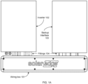
- FIG. 1A shows, schematically, an example wiring box 101, inverter 102, and backup interface 103 in a first configuration according to aspects of the disclosure.
- the inverter 102 and backup interface 103 may be referred to as "power devices.”
- other devices that may be installed near wiring box 101 may be referred to as “power devices,” such as energy storage devices (batteries), electrical vehicle chargers, load panels, load centers, breaker boxes, utility meters, main utility disconnect, fuel cell devices, heating units, cooling units, and heat exchanges.
- Inverter 102 and backup interface unit 103 are used here as examples of two power devices, but other power devices may be used as alternatives.
- wiring box 101 may be used to connect wires from two or more power devices.
- inverter 102 may be wired to backup interface unit 103 and an electrical distribution panel.
- Fittings 104 may be used between inverter 102 and wiring box 101.
- Fittings 104 may be straight and of a predetermined length.
- Fittings 104 may be used between backup interface unit 103 and wiring box 101.
- the wires between the two power devices may pass through fittings 104 and wiring box 101.
- the power devices are above wiring box 101, and inverter 102 is to the left of backup interface unit 103.
- This configuration may be turned 180 degrees and arranged so that wiring box 101 is above the power devices, such that inverter 102 is to the right of backup interface unit 103.
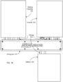
- FIG. 1B shows, schematically, an example wiring box 101 and power devices in a second configuration according to aspects of the disclosure.
- the power devices of this illustration show similar arrangement as FIG. 1A , but in a different configuration.
- the power devices are above and below wiring box 101, inverter 102 is to the right of backup interface unit 103, and battery 105 is below wiring box 101.
- This configuration may be turned 180 degrees, and arranged so that wiring box 101 is above the power devices, such that inverter 102 is to the left of backup interface unit 103, and battery 105 is above wiring box 101.
- Further configurations of power devices relative to the wiring box may include power devices above and below wiring box 101.
- Wiring box 101 kit may include separate fittings configured for each type of power device, such as inverter fittings 104A for an inverter and backup fittings 104B for a backup interface unit.
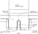
- Wiring box housing 101H may include tool recess 113 for positioning drill hole alignment tool 115 relative to cut-out holes in wiring box housing 101H.
- Drill hole alignment tool 115 positions a drill so that holes may be drilled into the wall behind wiring box 101, such as for a power device or a bracket for the respective power device.
- Cover 111 of wiring box 101 may be attached to wiring box housing 101H using bolts, screws, snap-fit connectors, or a combination thereof.
- Cover 111 of wiring box 101 may include a seal, such as an overmolded seal, an o-ring seal, or a gasket.
- Drill hole alignment tool 115 may include multiple drill holes 115C, where different drill holes may be configured to align different power devices.
- Alignment tool base recess 115A of drill hole alignment tool 115 may include alignment tool base recess 115B that can assist in positioning drill hole alignment tool 115 accurately relative to the cut-out holes.
- Drill hole alignment tool 115 may be configured for one or more of different kinds of power devices, such as different kinds of inverters, different kinds of backup interfaces, different kinds of electrical energy storage devices (batteries), and other devices associated with a power generation system.
- cut-outs may comprise pre-cut holes, areas manufactured for punch-out, areas marked to be cut out, or any other such aperture or area for creating an aperture.
- Wiring box housing 101H may include inverter fitting cut-outs 114A on the sides, such as cut-outs for more than one type of inverter. For example, each set of cut-outs is matched in number and location of the cut-outs to a different type of power device, such as a different make and/or model of inverter.
- Wiring box housing 101H may include backup fitting cut-outs 114B on the sides.
- Wiring box housing 101H may include auxiliary fitting marks 114C on the sides for cutting holes in wiring box housing 101H without damaging internal structures.
- Wiring box housing 101H may include tool recesses 113 on the sides of wiring box housing 101H and aligned with inverter fitting cut-outs 114A and/or backup fitting cut-outs 114B.
- Wiring box housing 101H may include vent cut-outs 117 on the sides. Vent cut-outs 117 may be used to insert breathing vents on the sides of wiring box housing 101H to allow air circulation and moisture drainage.
- Wiring box housing 101H may include alignment tool recesses 113 on both sides of wiring box housing 101H.
- Each tool recess 113 is configured to align drill holes for a power device bracket such that the fittings are aligned between the fitting holes of the power device and the cut-out fitting holes in wiring box housing 101H.
- Wiring box housing 101H may include multiple power device cut-outs, such as high-power inverter cut-outs 114AH and low-power inverter cut-outs 114AL.
- Wiring box housing 101H may include backup fitting cut-outs 114B on the sides.
- Wiring box housing 101H may include auxiliary fitting marks 114C on the sides for cutting holes in wiring box housing 101H without damaging internal structures.
- Wiring box housing 101H may include alignment tool recesses 113 on the sides of wiring box housing 101H and aligned with the cut-outs.
- Wiring box housing 101H may include vent cut-out 117 on the sides.
- Wiring box housing 101H may include multiple power device cut-outs, such as inverter fitting cut-outs 114A and backup fitting cut-outs 114B on both sides of wiring box housing 101H.
- Wiring box housing 101H may include auxiliary fitting marks 114C on both sides for cutting holes in wiring box housing 101H at auxiliary fitting region 114D without damaging internal structures.
- Wiring box housing 101H may include alignment tool recesses 113 on both sides of wiring box housing 101H.
- Tool recess 113 may include tool recess protrusion 113P to assist in positioning drill hole alignment tool 115 using recess 115B.
- Wiring box housing 101H may include vent cut-out 117 on the sides.
- Wiring box housing 101H may include one or more expansion cut-outs 116 on the left and right sides of wiring box housing 101H. Expansion cut-outs 116 may be used to expand wiring box housing 101H interconnect to a neighboring wiring box, combiner box, or power device located to the left or right sides of wiring box housing 101H.
- Wiring box housing 101H may include ground bar attachment 112A for attaching ground bar 112 to wiring box housing 101H.
- Drill hole alignment tools 115 may be positioned within tool recesses 113. Drill hole alignment tools 115 may be used to drill holes in the wall for attaching a power device securing brackets of the power device to the wall, such as inverter hanger bracket and backup interface unit hanger bracket.
- Wiring box housing 101H may include multiple alignment tool recesses 113.
- Alignment tool recess 113 may include tool recess protrusion 113P.
- Drill hole alignment tools 115 may include alignment tool base recess 115B configured to match tool recess protrusion 113P.
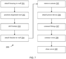
- wiring box housing 101H of wiring box 101 may be attached to a wall.
- drill hole alignment tool 115 may be positioned in alignment tool recess 113 of wiring box housing 101H.
- a hole may be drilled in the wall.
- a bracket of a power device may be attached to the hole in the wall.
- a set of cut-outs (e.g., 114A, 114AH, 114AL, or 114B) of wiring box housing 101H is removed, wherein the cut-outs removed correspond to the power device and the bracket of the power device installed at step 204.
- the corresponding power device is attached to the bracket of the power device.
- a plurality of fittings 104 are connected between wiring box housing 101H and the power device.
- a plurality of wires is electrically connected between the power device and wiring box housing 101H.
- a cover of wiring box housing 101H is attached to wiring box housing 101H.
- wiring box 101 Other devices may be included in wiring box 101, such as a switch, a circuit breaker, a relay, a residual-current circuit breaker, a ground fault circuit interrupter, a sensor, a microprocessor, a communication device, an arc detection device, an alarm, and/or a user interfaces.
- a switch such as a switch, a circuit breaker, a relay, a residual-current circuit breaker, a ground fault circuit interrupter, a sensor, a microprocessor, a communication device, an arc detection device, an alarm, and/or a user interfaces.
Landscapes
- Engineering & Computer Science (AREA)
- Architecture (AREA)
- Civil Engineering (AREA)
- Structural Engineering (AREA)
- Mechanical Engineering (AREA)
- Connection Or Junction Boxes (AREA)
Applications Claiming Priority (1)
| Application Number | Priority Date | Filing Date | Title |
|---|---|---|---|
| US202363504980P | 2023-05-30 | 2023-05-30 |
Publications (1)
| Publication Number | Publication Date |
|---|---|
| EP4472001A1 true EP4472001A1 (de) | 2024-12-04 |
Family
ID=91334872
Family Applications (1)
| Application Number | Title | Priority Date | Filing Date |
|---|---|---|---|
| EP24179112.8A Withdrawn EP4472001A1 (de) | 2023-05-30 | 2024-05-30 | Verdrahtungskasten für ein stromerzeugungssystem |
Country Status (2)
| Country | Link |
|---|---|
| US (1) | US20240405533A1 (de) |
| EP (1) | EP4472001A1 (de) |
Citations (2)
| Publication number | Priority date | Publication date | Assignee | Title |
|---|---|---|---|---|
| JP2014197974A (ja) * | 2013-03-08 | 2014-10-16 | 未来工業株式会社 | 配設体、配設体の配置方法、配設体配置装置及び配設体配置構造 |
| DE202019104816U1 (de) * | 2019-09-02 | 2019-09-12 | Kurt Falkowski | Schablone für die Installation von Wanddosen und Kit-of-parts umfassend die Schablone für die Installation von Wanddosen |
-
2024
- 2024-05-30 US US18/678,156 patent/US20240405533A1/en active Pending
- 2024-05-30 EP EP24179112.8A patent/EP4472001A1/de not_active Withdrawn
Patent Citations (2)
| Publication number | Priority date | Publication date | Assignee | Title |
|---|---|---|---|---|
| JP2014197974A (ja) * | 2013-03-08 | 2014-10-16 | 未来工業株式会社 | 配設体、配設体の配置方法、配設体配置装置及び配設体配置構造 |
| DE202019104816U1 (de) * | 2019-09-02 | 2019-09-12 | Kurt Falkowski | Schablone für die Installation von Wanddosen und Kit-of-parts umfassend die Schablone für die Installation von Wanddosen |
Non-Patent Citations (4)
| Title |
|---|
| ANONYMOUS: "Adjustable Floor Box Kit with White Cover THE FAST, EASY WAY TO PUT A PLUG ANYWHERE YOU NEED IT! - Eliminates extension cords - Great for home offices & entertainment rooms - Easy to use -kit includes everything you need!", 20 March 2003 (2003-03-20), pages 1 - 4, XP093206120, Retrieved from the Internet <URL:https://images.tradeservice.com/INSTALLATIONSHEETS/DIR100002/THOBETINST00088.pdf> [retrieved on 20240918] * |
| ANONYMOUS: "Puszka natynkowa 6410-20 90x90x40 IP54 odgalezna 14 otworów", 25 August 2019 (2019-08-25), pages 1 - 2, XP093206456, Retrieved from the Internet <URL:https://elektrogielda.com/22455-puszka-natynkowa-6410-20-90x90x40-ip54-odgalezna-14-otworow.html> [retrieved on 20240918] * |
| RENVU SOLAR EQUIPMENT DISTRIBUTION: "SolarEdge Installation Guide: How to Install SolarEdge | RENVU", 6 December 2013 (2013-12-06), XP093206484, Retrieved from the Internet <URL:https://www.youtube.com/watch?v=xX7ljmTV_GU> [retrieved on 20240919] * |
| U S Z K I I N S TA L A C Y J N E D L A W N I C E P: "Katalog Produktow", 25 August 2019 (2019-08-25), pages 1 - 33, XP093206454, Retrieved from the Internet <URL:https://elektrogielda.com/index.php?controller=attachment&id_attachment=14341> [retrieved on 20240918] * |
Also Published As
| Publication number | Publication date |
|---|---|
| US20240405533A1 (en) | 2024-12-05 |
Similar Documents
| Publication | Publication Date | Title |
|---|---|---|
| US20100288526A1 (en) | Electrical apparatus having quick connect components | |
| CN220341448U (zh) | 一种储能汇流柜 | |
| JP2019079738A (ja) | 蓄電池システム | |
| US9673602B2 (en) | System for isolating power conductors using cover assemblies | |
| WO2020228748A1 (zh) | 电源柜 | |
| US20240405533A1 (en) | Wiring Box for Power Generation System | |
| US7082728B1 (en) | Electrical box for use with insulated concrete form building systems | |
| CN212991859U (zh) | 一种十字花电缆桥架连接件 | |
| CN220440211U (zh) | 模块化箱变 | |
| CN112002616A (zh) | 一种带有保护机构的断路器 | |
| US11764552B2 (en) | Electrical panel with distributed energy resources compartment and pre-wiring for solar inverter connection | |
| CN104377557A (zh) | 一种微型断路器安装座 | |
| CN219106986U (zh) | 一种接线底盒 | |
| US11248807B2 (en) | Rough-in box for high wall minisplit (ductless) airconditioners | |
| CN224110348U (zh) | 模块化集成电池箱及具有其的动力电池 | |
| CN222692090U (zh) | 用于充电柜的集成箱以及充电柜 | |
| US20250247042A1 (en) | Building integrated photovoltaic system | |
| EP3748791B1 (de) | Vertikale busleitungsstützvorrichtung | |
| CN223693314U (zh) | 汇流排连接保护装置及电池装置 | |
| CN213278763U (zh) | 一种双面柜 | |
| JP4315439B2 (ja) | 地上設置用変圧器装置 | |
| JP7243802B1 (ja) | 電源装置、蓄電池箱、直流電源装置、及び取付方法 | |
| CN222785687U (zh) | 一种户外gis汇控柜 | |
| CN222128466U (zh) | 一种基于风冷技术的控制柜 | |
| CN220421188U (zh) | 测试电源集成柜 |
Legal Events
| Date | Code | Title | Description |
|---|---|---|---|
| PUAI | Public reference made under article 153(3) epc to a published international application that has entered the european phase |
Free format text: ORIGINAL CODE: 0009012 |
|
| STAA | Information on the status of an ep patent application or granted ep patent |
Free format text: STATUS: THE APPLICATION HAS BEEN PUBLISHED |
|
| AK | Designated contracting states |
Kind code of ref document: A1 Designated state(s): AL AT BE BG CH CY CZ DE DK EE ES FI FR GB GR HR HU IE IS IT LI LT LU LV MC ME MK MT NL NO PL PT RO RS SE SI SK SM TR |
|
| P01 | Opt-out of the competence of the unified patent court (upc) registered |
Free format text: CASE NUMBER: APP_64414/2024 Effective date: 20241205 |
|
| STAA | Information on the status of an ep patent application or granted ep patent |
Free format text: STATUS: THE APPLICATION HAS BEEN WITHDRAWN |
|
| 18W | Application withdrawn |
Effective date: 20250513 |