EP4471997A1 - Kabel und elektronische vorrichtung - Google Patents
Kabel und elektronische vorrichtung Download PDFInfo
- Publication number
- EP4471997A1 EP4471997A1 EP22923596.5A EP22923596A EP4471997A1 EP 4471997 A1 EP4471997 A1 EP 4471997A1 EP 22923596 A EP22923596 A EP 22923596A EP 4471997 A1 EP4471997 A1 EP 4471997A1
- Authority
- EP
- European Patent Office
- Prior art keywords
- interface
- cable
- processing circuit
- detection signal
- analog
- Prior art date
- Legal status (The legal status is an assumption and is not a legal conclusion. Google has not performed a legal analysis and makes no representation as to the accuracy of the status listed.)
- Pending
Links
Images

Classifications
-
- G—PHYSICS
- G08—SIGNALLING
- G08B—SIGNALLING SYSTEMS, e.g. PERSONAL CALLING SYSTEMS; ORDER TELEGRAPHS; ALARM SYSTEMS
- G08B5/00—Visible signalling systems, e.g. visible personal calling systems or remote indication of seats occupied
- G08B5/22—Visible signalling systems, e.g. visible personal calling systems or remote indication of seats occupied using electric transmission; using electromagnetic transmission
- G08B5/36—Visible signalling systems, e.g. visible personal calling systems or remote indication of seats occupied using electric transmission; using electromagnetic transmission using visible light sources
-
- H—ELECTRICITY
- H01—ELECTRIC ELEMENTS
- H01R—ELECTRICALLY-CONDUCTIVE CONNECTIONS; STRUCTURAL ASSOCIATIONS OF A PLURALITY OF MUTUALLY-INSULATED ELECTRICAL CONNECTING ELEMENTS; COUPLING DEVICES; CURRENT COLLECTORS
- H01R31/00—Coupling parts supported only by co-operation with counterpart
- H01R31/06—Intermediate parts for linking two coupling parts, e.g. adapter
- H01R31/065—Intermediate parts for linking two coupling parts, e.g. adapter with built-in electric apparatus
-
- G—PHYSICS
- G08—SIGNALLING
- G08B—SIGNALLING SYSTEMS, e.g. PERSONAL CALLING SYSTEMS; ORDER TELEGRAPHS; ALARM SYSTEMS
- G08B3/00—Audible signalling systems, e.g. audible personal calling systems
- G08B3/10—Audible signalling systems, e.g. audible personal calling systems using electric transmission; using electromagnetic transmission
-
- G—PHYSICS
- G08—SIGNALLING
- G08B—SIGNALLING SYSTEMS, e.g. PERSONAL CALLING SYSTEMS; ORDER TELEGRAPHS; ALARM SYSTEMS
- G08B7/00—Signalling systems according to two or more of groups G08B3/00 - G08B6/00
- G08B7/06—Signalling systems according to two or more of groups G08B3/00 - G08B6/00 using electric transmission, e.g. involving audible and visible signalling through the use of sound and light sources
-
- H—ELECTRICITY
- H01—ELECTRIC ELEMENTS
- H01R—ELECTRICALLY-CONDUCTIVE CONNECTIONS; STRUCTURAL ASSOCIATIONS OF A PLURALITY OF MUTUALLY-INSULATED ELECTRICAL CONNECTING ELEMENTS; COUPLING DEVICES; CURRENT COLLECTORS
- H01R13/00—Details of coupling devices of the kinds covered by groups H01R12/70 or H01R24/00 - H01R33/00
- H01R13/66—Structural association with built-in electrical component
- H01R13/665—Structural association with built-in electrical component with built-in electronic circuit
- H01R13/6683—Structural association with built-in electrical component with built-in electronic circuit with built-in sensor
-
- H—ELECTRICITY
- H01—ELECTRIC ELEMENTS
- H01R—ELECTRICALLY-CONDUCTIVE CONNECTIONS; STRUCTURAL ASSOCIATIONS OF A PLURALITY OF MUTUALLY-INSULATED ELECTRICAL CONNECTING ELEMENTS; COUPLING DEVICES; CURRENT COLLECTORS
- H01R31/00—Coupling parts supported only by co-operation with counterpart
- H01R31/06—Intermediate parts for linking two coupling parts, e.g. adapter
-
- G—PHYSICS
- G08—SIGNALLING
- G08B—SIGNALLING SYSTEMS, e.g. PERSONAL CALLING SYSTEMS; ORDER TELEGRAPHS; ALARM SYSTEMS
- G08B13/00—Burglar, theft or intruder alarms
- G08B13/02—Mechanical actuation
- G08B13/14—Mechanical actuation by lifting or attempted removal of hand-portable articles
- G08B13/1409—Mechanical actuation by lifting or attempted removal of hand-portable articles for removal detection of electrical appliances by detecting their physical disconnection from an electrical system, e.g. using a switch incorporated in the plug connector
- G08B13/1418—Removal detected by failure in electrical connection between the appliance and a control centre, home control panel or a power supply
-
- H—ELECTRICITY
- H01—ELECTRIC ELEMENTS
- H01R—ELECTRICALLY-CONDUCTIVE CONNECTIONS; STRUCTURAL ASSOCIATIONS OF A PLURALITY OF MUTUALLY-INSULATED ELECTRICAL CONNECTING ELEMENTS; COUPLING DEVICES; CURRENT COLLECTORS
- H01R13/00—Details of coupling devices of the kinds covered by groups H01R12/70 or H01R24/00 - H01R33/00
- H01R13/66—Structural association with built-in electrical component
- H01R13/717—Structural association with built-in electrical component with built-in light source
-
- H—ELECTRICITY
- H01—ELECTRIC ELEMENTS
- H01R—ELECTRICALLY-CONDUCTIVE CONNECTIONS; STRUCTURAL ASSOCIATIONS OF A PLURALITY OF MUTUALLY-INSULATED ELECTRICAL CONNECTING ELEMENTS; COUPLING DEVICES; CURRENT COLLECTORS
- H01R24/00—Two-part coupling devices, or either of their cooperating parts, characterised by their overall structure
- H01R24/60—Contacts spaced along planar side wall transverse to longitudinal axis of engagement
Definitions
- the invention relates to cable technology, in particular to a cable with a plugging and unplugging detection function and a corresponding electronic device.
- a UPS device with an interface monitoring device is proposed.
- the UPS device is equipped with an interface monitoring device.
- the interface monitoring device includes several micro pressure sensors, microprocessors, and alarms.
- the processors are connected to the micro pressure sensors and alarm signals respectively.
- the interface monitoring device can alarm through an alarm and prompt the staff to reinsert the cable plug into place to ensure the normal operation of the UPS device.
- the cable plugging and unplugging detection of the prior art often relies on the operation of electronic device.
- an interface monitoring device needs to be additionally set in the UPS device and the corresponding interface monitoring steps need to be executed.
- This causes the cable plugging and unplugging detection technology to need to be specially designed or improved for an electronic device. It is not universal for all electronic devices, which hinders the wide application of cable plugging and unplugging detection technology. Therefore, there is a great need for a cable plugging and unplugging detection technology that can be used directly in all electronic devices without the need for special design or modification.
- the main purpose of the present disclosure is to solve the problems of poor universality and weak application scalability of current cable plugging and unplugging detection technology.
- the present disclosure proposes a cable, including a first interface, a second interface, and a wire electrically connecting the first interface and the second interface.
- the first interface and the second interface are respectively used to connect the master device interface and the slave device interface.
- the cable also comprises: a sensor, at least one of the first interface and the second interface, for detecting whether the first interface and/or the second interface are inserted into the device interface and generating an analog detection signal;
- the processing circuit includes an analog-to-digital conversion element, which is connected to the output end of the sensor, and is used to generate a digital detection signal after analog-to-digital conversion of the analog detection signal output by the sensor.
- the cable also includes a power line for connecting the processing circuit and the power supply terminal of the main device interface, so that the processing circuit is powered by the main device interface.
- the processing circuit includes a rechargeable battery, and the charging end of the rechargeable battery is connected to the power line so that it can be charged through the power line, while supplying power to the processing circuit.
- the cable also includes a battery for powering the processing circuit.
- the processing circuit also includes an amplifier for amplifying the digital signal generated by the analog-to-digital conversion element.
- the processing circuit also includes an indicator light for indicating the state of the digital detection signal.
- the number of the indicator lights corresponds to the number of sensors to respectively indicate the status of digital detection signals from different sensors.
- the processing circuit also includes an audible alarm which gives an audible alarm when the digital detection signal is in a predetermined state.
- the cable also includes a detection line, which is used to transmit the analog detection signal output by the sensor to the analog digital conversion element.
- the disclosure provides an electronic device, including the aforementioned cable and the main device interface connecting the cable.
- the electronic device also includes a warning device, which is used to receive and process the digital detection signal from the main device interface to perform the warning operation according to the status of the digital detection signal.
- the cable of the invention has simple structure and low cost, and can easily realize the plugging and unplugging detection of the cable without redesign or modification the electronic device interface.
- the present disclosure takes a different approach. Instead of seeking to implement plugging and unplugging detection on the interface of an electronic device or electronic equipment, the plugging and unplugging detection function is implemented on the cable. In this way, it is not necessary to redesign or modify the electronic device, but only to replace the existing cable with the cable of the invention to achieve plugging and unplugging detection, thus greatly improving the versatility of the technology and the universality of application.
- the “cable” in this disclosure generally refers to an electronic cable; that is, the cable includes at least one pair of wires capable of transmitting current or electronic signals.
- the present disclosure does not exclude that it can be applied to some optical cables for transmitting optical signals, as long as the optical cables can contain wires for transmitting electronic signals.
- the said cable in the present disclosure has no restrictions on the interface to which it is connected, and the interface to which it is connected can be an existing interface type conforming to specific standards, or a special interface not defined according to standards.
- the cable in the present disclosure includes at least two interfaces, which are referred to here as the first interface and the second interface for distinguishing.
- the cable should also at least include the interface wire electrically connected.
- the wire can be used to transmit current, and the current can be used as the carrier of energy or signal.
- the present disclosure is not limited to the function of the current transmitted in the wire.
- a cable may include more than two interfaces. Therefore, the first interface and the second interface referred to in this disclosure do not refer to a particular interface, but may also include more than one interface. The first interface and the second interface essentially refer to different interfaces distinguished by different energy or signal inflow and outflow.
- the first interface and the second interface are respectively used to connect a master device interface and a slave device interface.
- the master device interface and slave device interface here correspond to the master device and slave device respectively.
- the master device and the slave device are not the master and slave devices in terms of the function of the device itself, but the device that receives the plugging and unplugging detection signal is called the master device, and the device that does not receive the plugging and unplugging detection signal is called the slave device. The generation and transmission of the plugging and unplugging detection signal will be described below.
- the cable of the present disclosure also includes a sensor, which is located with at least one of the first interface and the second interface, and is used to detect whether the first interface and/or the second interface are inserted into the device interface and generate a detection signal.
- a sensor which is located with at least one of the first interface and the second interface, and is used to detect whether the first interface and/or the second interface are inserted into the device interface and generate a detection signal.
- This disclosure is not limited to specific sensor types for plugging and unplugging detection, for example, piezoelectric sensors, Hall sensors, photoelectric sensors, photoresistors, micro sensors, distance sensors or MEMS based sensors can be used. In the present disclosure, it is preferred to adopt piezoelectric sensors and generate analog detection signals.
- the cable of the present disclosure also includes a processing circuit, which includes an analog-to-digital conversion element which is connected to the output end of the sensor to generate a digital detection signal after analog-to-digital conversion of the analog detection signal output by the sensor.
- the digital detection signal is transmitted from the processing circuit to the main device interface.
- the master device interface is an interface located on the master device, and correspondingly, the slave device interface is an interface located on the slave device.
- the disclosure has no restrictions on the functions of the master device and the slave device, and no restrictions on the operating system and interface type of the device. That is, in principle, the present disclosure can be applied to any electronic device. In particular, the present disclosure is more applicable to industrial control hosts such as industrial computers with special operating systems, wherein it is not convenient to install software, and whose interfaces are also complex.
- This disclosure sets both the sensor and the processing circuit in the cable. Since it is unnecessary to set a sensor or processing circuit in the device interface, the device can be provided with a feature of plugging and unplugging detection without special design or modification.
- the processing circuit can also include an amplifier to amplify the digital signal generated by the analog digital conversion element. After the signal is amplified, it is beneficial to transmit the signal to a longer distance.
- the present disclosure chooses to transmit the detection signal to the main device interface, this does not mean that the detection signal must be processed in the main device.
- the main device provides a corresponding processing program or processing software to process the detection signal and then perform further actions.
- the cable itself can also react or act on the detection signal, so that the cable with plugging and unplugging detection in the present disclosure can be plug_and_play, without causing additional burden on the main device.
- the processing circuit of the present disclosure also includes an indicator light, which can be used to indicate the state of the digital detection signal.
- the analog to digital converter converts the analog detection signal into a digital detection signal.
- the status of the digital detection signal represents the plugging or unplugging status detected by the sensor. Therefore, in order to directly display the plugging or unplugging status, the indicator light is used to display the status of the digital detection signal, so that the user can clearly know the plugging or unplugging status of the corresponding interface of the current cable.
- the LED light can be used to indicate that the corresponding cable connector is not inserted or pulled out.
- the color of the indicator light can also be used; for example, the red LED indicates that the cable connector is not inserted or pulled out, and the green LED indicates that the cable connector is inserted.
- the number of the indicator lights can correspond to the number of sensors, so as to indicate the status of digital detection signals from different sensors respectively.
- the processing circuit of the present disclosure also includes an audible alarm, such as a buzzer, and when the digital detection signal is in a predetermined state, the audible alarm performs an audible alarm. For example, when the plugging or unplugging status indicated by the digital detection signal is not connected or unplugged, the buzzer will beep for alarm.
- an audible alarm such as a buzzer
- the detection signal is transmitted to the main device interface, and the main device can process the detection signal.
- the main device includes an alarm means, which is used to receive and process the digital detection signal from the main device interface to perform alarm operation according to the status of the digital detection signal.
- the alarm operation such as sound, light, electricity and other alarms, can also be to send specific information to specific central control device, or warn terminal device of specific personnel through telephone, SMS and other means.
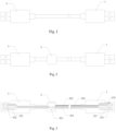
- Fig. 1 is the structural diagram of an embodiment of a USB cable in the prior art.
- the USB cable includes a first interface 1 and a second interface 2, and the first interface 1 and the second interface 2 are connected by a wire part.
- Fig. 2 shows the structure of a USB cable of the present disclosure.
- the wire routing of the cable the present invention also includes a convex cavity part 3.
- Fig. 3 is a sectional view of the first embodiment of the USB cable shown in Fig. 2 .
- the first interface 1 of the USB cable is provided with a plurality of first terminals 101
- the second interface 2 is provided with a plurality of second terminals 201.
- the first terminal 101 and the second terminal 201 are connected through a wire 401.
- the cavity part 3 is provided with a processing circuit 301, which can be constructed of a sheet-shaped circuit board and circuit elements on it.
- the wire 401 is not in contact with the circuit part of the processing circuit 301, that is, the processing circuit 301 does not affect the signal transmission of the wire 401.
- the processing circuit 301 at least includes an analog digital conversion element.
- the first interface 1 and the second interface 2 of this embodiment are also equipped with sensors, which are used to detect the plugging or unplugging status of the interface.
- the first sensor 102 is in the first interface 1
- the second sensor 202 is in the second interface 2.
- the first sensor 102 and the second sensor 202 are connected with the processing circuit 301 through the detection line 302.
- the detection line is used to transmit the analog detection signal output by the first sensor 102 and the second sensor 202 to the analog-to-digital conversion element (not shown in Fig. 3 ) of the processing circuit 301.
- the analog-to-digital conversion element is used for analog-to-digital conversion of analog detection signals output from the first sensor 102 and the second sensor 202 to generate a digital detection signal, which is transmitted to the main device interface by the processing circuit.
- the analog-to-digital conversion element is, for example, an analog-to-digital converter, which can be one or two. When the number of the analog-to-digital converter is one, it has multiple inputs and multiple outputs to convert the analog detection signals of the first sensor 102 and the second sensor 202 into two digital detection signals respectively. When there are two analog-to-digital converters, they respectively receive analog detection signals from the first sensor 102 and the second sensor 202 and output digital detection signals.
- the two output digital detection signals are transmitted to the electronic device connected with the first interface 1 through the signal line (not shown in Fig. 3 ).
- the signal line not shown in Fig. 3 .
- the processing circuit 301 of the cable is powered by the main device interface. Therefore, the cable also includes a power line 303, which is connected with the processing circuit 301 and the power supply terminal 103 of the main device interface, so that the processing circuit is powered by the main device interface.
- the power supply terminal 103 in this embodiment is different from the first terminal 101, that is, it is an independent power supply terminal.
- the power supply terminal can also be realized by some terminals with power supply function in the first terminal 101.
- the power line is connected to two terminals with power supply function in the first terminal 101 of the USB cable. It should be noted that although it is not specially drawn in Figs.
- the power line 303 usually includes two wires, so it usually needs to be connected to two terminals.
- a voltage stabilizing circuit or a current stabilizing circuit can be set in the processing circuit.
- corresponding voltage conversion elements or related circuits can be set in the processing circuit.
- Fig. 5 is a sectional view of the USB cable of the third embodiment of the present disclosure.
- a rechargeable battery can be set in the processing circuit, and the charging end of the rechargeable battery is connected to the power line 303.
- the rechargeable battery charges through the power line, and supplies power to the processing circuit 301 at the same time.
- Corresponding charging and discharging circuits can be provided in the processing circuit 301 for support.
- the main device interface can supply power to the rechargeable battery in the processing circuit 301.
- the rechargeable battery can continue to supply power to the processing circuit to provide signal processing and alarm operation.
- Fig. 6 is a sectional view of the USB cable of the fourth embodiment of the present disclosure.
- the embodiment does not include a power line 303, but instead includes a battery 304 in the cavity part 3.
- a detachable and universal button battery can be used.
- the cavity part 3 needs to be provided with a battery cavity and a corresponding cover plate.
- the battery holding chamber and the corresponding cover plate are the conventional structures of electronic device, so they will not be repeated here.
- the USB cable also includes a wire sleeve, the signal line, detection line, power line, etc. are all wrapped in the wire sleeve, the cavity part is located between the first interface and the second interface, and the wire sleeve also covers the cavity part.
- the above embodiments only take the USB cable as an example, that is, the first interface 1 and the second interface 2 of the above embodiments are interface types compatible with the USB standard.
- the present disclosure is not limited to the interface type of the upper body.
- any cable that transmits power or signal and has a plugging and unplugging detection requirement can be applied to the present disclosure, such as serial port line and network port line.
- modules in the device in the embodiment can be adaptively changed and set in one or more devices different from the embodiment.
- the modules or units or components in the embodiment can be combined into one module or unit or component, and they can be divided into multiple sub modules or sub units or sub components. Except that at least some of such features and/or processes or units are mutually exclusive, any combination may be used to combine all features disclosed in the specification (including accompanying claims, abstract and drawings) and all processes or units of any method or device so disclosed. Unless otherwise expressly stated, each feature disclosed in the specification (including accompanying claims, abstract and drawings) can be replaced by providing alternative features for the same, equivalent or similar purposes.
Landscapes
- Physics & Mathematics (AREA)
- General Physics & Mathematics (AREA)
- Engineering & Computer Science (AREA)
- Microelectronics & Electronic Packaging (AREA)
- Electromagnetism (AREA)
- Insulated Conductors (AREA)
- Details Of Connecting Devices For Male And Female Coupling (AREA)
Applications Claiming Priority (2)
| Application Number | Priority Date | Filing Date | Title |
|---|---|---|---|
| CN202220204993.4U CN216903609U (zh) | 2022-01-25 | 2022-01-25 | 线缆和电子设备 |
| PCT/CN2022/141296 WO2023142810A1 (zh) | 2022-01-25 | 2022-12-23 | 线缆和电子设备 |
Publications (2)
| Publication Number | Publication Date |
|---|---|
| EP4471997A1 true EP4471997A1 (de) | 2024-12-04 |
| EP4471997A4 EP4471997A4 (de) | 2026-03-18 |
Family
ID=82180357
Family Applications (1)
| Application Number | Title | Priority Date | Filing Date |
|---|---|---|---|
| EP22923596.5A Pending EP4471997A4 (de) | 2022-01-25 | 2022-12-23 | Kabel und elektronische vorrichtung |
Country Status (6)
| Country | Link |
|---|---|
| US (1) | US20240378972A1 (de) |
| EP (1) | EP4471997A4 (de) |
| JP (1) | JP3249693U (de) |
| KR (1) | KR20240001285U (de) |
| CN (1) | CN216903609U (de) |
| WO (1) | WO2023142810A1 (de) |
Families Citing this family (2)
| Publication number | Priority date | Publication date | Assignee | Title |
|---|---|---|---|---|
| CN216903609U (zh) * | 2022-01-25 | 2022-07-05 | 北京博衍思创信息科技有限公司 | 线缆和电子设备 |
| CN118352851A (zh) * | 2024-04-01 | 2024-07-16 | 华为技术有限公司 | 线缆、供电设备和受电设备 |
Family Cites Families (11)
| Publication number | Priority date | Publication date | Assignee | Title |
|---|---|---|---|---|
| US9138180B1 (en) * | 2010-05-03 | 2015-09-22 | Masimo Corporation | Sensor adapter cable |
| SE540862C2 (en) * | 2016-04-13 | 2018-12-04 | South Coast Eng Ab | Cable with sensor device and alarm unit |
| CN106374298A (zh) * | 2016-11-21 | 2017-02-01 | 李雄 | 带漏电告警usb线 |
| JP2019125428A (ja) * | 2018-01-12 | 2019-07-25 | Fxc株式会社 | ケーブル挿抜検出機能付電子機器 |
| SE543173C2 (en) * | 2018-07-02 | 2020-10-20 | Jondetech Sensors Ab Publ | Adapter device with infrared sensor and heat protection switch |
| KR102818549B1 (ko) * | 2019-02-25 | 2025-06-10 | 스냅 인코포레이티드 | 충전 상태 표시가 있는 충전 케이블 |
| WO2020185098A1 (en) * | 2019-03-11 | 2020-09-17 | Project X51 Limited | Illuminated charging connector or device and electronic device or system operable based on packaging status |
| CN209046357U (zh) | 2019-03-29 | 2019-06-28 | 海南韬世科技有限公司 | 一种带接口监控装置的ups设备 |
| CN209881017U (zh) * | 2019-06-21 | 2019-12-31 | 优奈柯恩(北京)科技有限公司 | 连接器 |
| US11323140B2 (en) * | 2020-01-27 | 2022-05-03 | Anritsu Corporation | Signal generation apparatus and signal generation method |
| CN216903609U (zh) * | 2022-01-25 | 2022-07-05 | 北京博衍思创信息科技有限公司 | 线缆和电子设备 |
-
2022
- 2022-01-25 CN CN202220204993.4U patent/CN216903609U/zh active Active
- 2022-12-23 JP JP2024600119U patent/JP3249693U/ja active Active
- 2022-12-23 KR KR2020247000034U patent/KR20240001285U/ko active Pending
- 2022-12-23 WO PCT/CN2022/141296 patent/WO2023142810A1/zh not_active Ceased
- 2022-12-23 EP EP22923596.5A patent/EP4471997A4/de active Pending
-
2024
- 2024-07-23 US US18/781,999 patent/US20240378972A1/en active Pending
Also Published As
| Publication number | Publication date |
|---|---|
| JP3249693U (ja) | 2025-01-08 |
| WO2023142810A1 (zh) | 2023-08-03 |
| CN216903609U (zh) | 2022-07-05 |
| EP4471997A4 (de) | 2026-03-18 |
| US20240378972A1 (en) | 2024-11-14 |
| KR20240001285U (ko) | 2024-07-26 |
Similar Documents
| Publication | Publication Date | Title |
|---|---|---|
| US20240378972A1 (en) | Cable and Electronic Device | |
| KR101374638B1 (ko) | 모바일 디바이스 자동 검출 장치 및 방법 | |
| US20180254648A1 (en) | Applying Alternate Modes of USB Type-C for Fast Charging Systems | |
| US8712196B2 (en) | Optical cable plug-in detection | |
| CN114041249B (zh) | 连接器及利用连接器进行充电控制的方法 | |
| US20070054550A1 (en) | Multi-device power charger and data communication device | |
| WO2022199231A1 (zh) | 一种无线键盘 | |
| TW201525660A (zh) | 具有音訊輸出之銜接台 | |
| NZ574606A (en) | Improved medical interface with a slow continuous data rate and faster intermittent data rate | |
| US20220280020A1 (en) | Power-adaptable device for scanning a human intra-cavity | |
| CN103487633A (zh) | 一种非接触式高压线验电器 | |
| CN110137755B (zh) | 连接器和包括连接器的第二电子设备 | |
| US20150039794A1 (en) | Multifunction Interface for Patient Monitoring | |
| JP2016530627A (ja) | 電気機械的アダプタ | |
| JP2002116853A (ja) | Usb搭載電子機器及びそれに用いるusbケーブル | |
| CN101189592A (zh) | 双usb端口设备 | |
| CN209046357U (zh) | 一种带接口监控装置的ups设备 | |
| CN218161098U (zh) | 电缆连接器 | |
| CN210573761U (zh) | 接口转换电路及信号检测装置 | |
| US10698467B2 (en) | Emergency power off devices | |
| CN210665994U (zh) | Usb接口负载检测装置、系统及usb连接装置 | |
| CN210111096U (zh) | 一种接口和电子设备 | |
| TW201935260A (zh) | 電子裝置 | |
| CN223334162U (zh) | 一种电缆端头连接器 | |
| CN112399298A (zh) | 无线耳机、无线耳机盒及无线耳机状态检测方法 |
Legal Events
| Date | Code | Title | Description |
|---|---|---|---|
| STAA | Information on the status of an ep patent application or granted ep patent |
Free format text: STATUS: THE INTERNATIONAL PUBLICATION HAS BEEN MADE |
|
| PUAI | Public reference made under article 153(3) epc to a published international application that has entered the european phase |
Free format text: ORIGINAL CODE: 0009012 |
|
| STAA | Information on the status of an ep patent application or granted ep patent |
Free format text: STATUS: REQUEST FOR EXAMINATION WAS MADE |
|
| 17P | Request for examination filed |
Effective date: 20240823 |
|
| AK | Designated contracting states |
Kind code of ref document: A1 Designated state(s): AL AT BE BG CH CY CZ DE DK EE ES FI FR GB GR HR HU IE IS IT LI LT LU LV MC ME MK MT NL NO PL PT RO RS SE SI SK SM TR |
|
| DAV | Request for validation of the european patent (deleted) | ||
| DAX | Request for extension of the european patent (deleted) | ||
| A4 | Supplementary search report drawn up and despatched |
Effective date: 20260218 |
|
| RIC1 | Information provided on ipc code assigned before grant |
Ipc: H01R 13/66 20060101AFI20260212BHEP Ipc: H01R 31/06 20060101ALI20260212BHEP Ipc: H01R 13/717 20060101ALI20260212BHEP Ipc: H01R 24/60 20110101ALN20260212BHEP Ipc: G08B 13/14 20060101ALN20260212BHEP |