EP4471979A1 - Electrical member contact device and antenna module comprising same - Google Patents
Electrical member contact device and antenna module comprising same Download PDFInfo
- Publication number
- EP4471979A1 EP4471979A1 EP23747205.5A EP23747205A EP4471979A1 EP 4471979 A1 EP4471979 A1 EP 4471979A1 EP 23747205 A EP23747205 A EP 23747205A EP 4471979 A1 EP4471979 A1 EP 4471979A1
- Authority
- EP
- European Patent Office
- Prior art keywords
- gasket
- frame
- fastening hole
- electrical member
- contact device
- Prior art date
- Legal status (The legal status is an assumption and is not a legal conclusion. Google has not performed a legal analysis and makes no representation as to the accuracy of the status listed.)
- Pending
Links
Images




Classifications
-
- H—ELECTRICITY
- H01—ELECTRIC ELEMENTS
- H01R—ELECTRICALLY-CONDUCTIVE CONNECTIONS; STRUCTURAL ASSOCIATIONS OF A PLURALITY OF MUTUALLY-INSULATED ELECTRICAL CONNECTING ELEMENTS; COUPLING DEVICES; CURRENT COLLECTORS
- H01R12/00—Structural associations of a plurality of mutually-insulated electrical connecting elements, specially adapted for printed circuits, e.g. printed circuit boards [PCB], flat or ribbon cables, or like generally planar structures, e.g. terminal strips, terminal blocks; Coupling devices specially adapted for printed circuits, flat or ribbon cables, or like generally planar structures; Terminals specially adapted for contact with, or insertion into, printed circuits, flat or ribbon cables, or like generally planar structures
- H01R12/70—Coupling devices
- H01R12/71—Coupling devices for rigid printing circuits or like structures
- H01R12/712—Coupling devices for rigid printing circuits or like structures co-operating with the surface of the printed circuit or with a coupling device exclusively provided on the surface of the printed circuit
- H01R12/714—Coupling devices for rigid printing circuits or like structures co-operating with the surface of the printed circuit or with a coupling device exclusively provided on the surface of the printed circuit with contacts abutting directly the printed circuit; Button contacts therefore provided on the printed circuit
-
- H—ELECTRICITY
- H01—ELECTRIC ELEMENTS
- H01Q—ANTENNAS, i.e. RADIO AERIALS
- H01Q1/00—Details of, or arrangements associated with, antennas
- H01Q1/12—Supports; Mounting means
- H01Q1/20—Resilient mountings
-
- H—ELECTRICITY
- H01—ELECTRIC ELEMENTS
- H01Q—ANTENNAS, i.e. RADIO AERIALS
- H01Q1/00—Details of, or arrangements associated with, antennas
- H01Q1/005—Damping of vibrations; Means for reducing wind-induced forces
-
- H—ELECTRICITY
- H01—ELECTRIC ELEMENTS
- H01R—ELECTRICALLY-CONDUCTIVE CONNECTIONS; STRUCTURAL ASSOCIATIONS OF A PLURALITY OF MUTUALLY-INSULATED ELECTRICAL CONNECTING ELEMENTS; COUPLING DEVICES; CURRENT COLLECTORS
- H01R12/00—Structural associations of a plurality of mutually-insulated electrical connecting elements, specially adapted for printed circuits, e.g. printed circuit boards [PCB], flat or ribbon cables, or like generally planar structures, e.g. terminal strips, terminal blocks; Coupling devices specially adapted for printed circuits, flat or ribbon cables, or like generally planar structures; Terminals specially adapted for contact with, or insertion into, printed circuits, flat or ribbon cables, or like generally planar structures
- H01R12/70—Coupling devices
- H01R12/7076—Coupling devices for connection between PCB and component, e.g. display
-
- H—ELECTRICITY
- H01—ELECTRIC ELEMENTS
- H01R—ELECTRICALLY-CONDUCTIVE CONNECTIONS; STRUCTURAL ASSOCIATIONS OF A PLURALITY OF MUTUALLY-INSULATED ELECTRICAL CONNECTING ELEMENTS; COUPLING DEVICES; CURRENT COLLECTORS
- H01R13/00—Details of coupling devices of the kinds covered by groups H01R12/70 or H01R24/00 - H01R33/00
- H01R13/02—Contact members
- H01R13/22—Contacts for co-operating by abutting
- H01R13/24—Contacts for co-operating by abutting resilient; resiliently-mounted
- H01R13/2407—Contacts for co-operating by abutting resilient; resiliently-mounted characterized by the resilient means
- H01R13/2414—Contacts for co-operating by abutting resilient; resiliently-mounted characterized by the resilient means conductive elastomers
-
- H—ELECTRICITY
- H01—ELECTRIC ELEMENTS
- H01R—ELECTRICALLY-CONDUCTIVE CONNECTIONS; STRUCTURAL ASSOCIATIONS OF A PLURALITY OF MUTUALLY-INSULATED ELECTRICAL CONNECTING ELEMENTS; COUPLING DEVICES; CURRENT COLLECTORS
- H01R13/00—Details of coupling devices of the kinds covered by groups H01R12/70 or H01R24/00 - H01R33/00
- H01R13/02—Contact members
- H01R13/22—Contacts for co-operating by abutting
- H01R13/24—Contacts for co-operating by abutting resilient; resiliently-mounted
- H01R13/2435—Contacts for co-operating by abutting resilient; resiliently-mounted with opposite contact points, e.g. C beam
-
- H—ELECTRICITY
- H01—ELECTRIC ELEMENTS
- H01R—ELECTRICALLY-CONDUCTIVE CONNECTIONS; STRUCTURAL ASSOCIATIONS OF A PLURALITY OF MUTUALLY-INSULATED ELECTRICAL CONNECTING ELEMENTS; COUPLING DEVICES; CURRENT COLLECTORS
- H01R2201/00—Connectors or connections adapted for particular applications
- H01R2201/02—Connectors or connections adapted for particular applications for antennas
Definitions
- Embodiments of the present disclosure relate to an electrical member contact device and an antenna module comprising same, and more particularly, to an electrical member contact device that protects the contact stability of a contact point between an antenna contact device and a substrate from external environmental factors such as vibration by improving the shape of a contact part, and an antenna module comprising same.
- vehicle antennas refer to various types of antennas mounted inside/outside of a vehicle for communication between wireless communication devices used in the vehicle.
- wireless communication devices used in a vehicle such as AM/FM radios, digital multimedia broadcast (DMB) receivers, global positioning systems (GPS), and vehicle mobile communication devices are extensively used and diversified, there are rapidly increasing requests for vehicle antenna manufacturing techniques of supporting multiple frequency bands while improving durability against vibration and shock occurring in vehicle environments and ensuring the stability and reliability of an antenna operation.
- DMB digital multimedia broadcast
- GPS global positioning systems
- the related arts have adopted a feeding method using the restoring force of a part of an antenna radiator.
- the restoring force is reduced due to long-term use.
- a feeding area is in the form of a contact point, there is a problem in that contact resistance increases due to environmental factors such as external shock or vibration.
- An object of the present disclosure is to provide an electrical member contact device capable of improving the stability and reliability of an antenna operation despite of external shock and vibration by improving a feeding structure of an antenna, and an antenna module comprising same.
- An object of the present disclosure is to provide an electrical member contact device capable of providing measures for preventing an antenna radiator from being separated from a gasket when the restoring force of the antenna radiator is reduced due to long-term used, and an antenna module comprising same.
- the frame may be curved past the first surface being the upper part of the gasket, may protrude out of the fastening hole by penetrating the fastening hole, and may be curved again so that an end of the frame is fixed to the gasket.
- the frame may be made of an elastic material.
- the gasket may be made of an elastic material.
- the gasket may include a fitting guide part provided in a direction penetrating the fastening hole so that the end of the frame is fixed by fitting into the gasket.
- the gasket may include a second surface located facing the first surface and provided to be electrically conductive in contact with a substrate.
- the frame may include: a contact part formed in a 'C' shape while surrounding the first surface and the third surface; and a support part electrically connected to the contact part, arranged between the third surface and the fourth surface, and formed in a 'C' shape to form a curve protruding out of the fastening hole, an end of the support part being fixed to the gasket.
- the contact part may be connected to the support part in a region where the third surface is arranged.
- the frame may be curved past the first surface being the upper part of the gasket, may protrude out of the fastening hole by penetrating the fastening hole, and may be curved again so that an end of the frame is fixed to the gasket.
- the frame may be made of an elastic material.
- the gasket may be made of an elastic material.
- the gasket may include a fitting guide part provided in a direction penetrating the fastening hole so that the end of the frame is fixed by fitting into the gasket.
- the frame may include a protrusion formed to protrude into contact with a side surface of the gasket in order to fix the frame.
- the gasket may include a second surface located facing the first surface and provided to be electrically conductive in contact with a substrate, and the fastening hole may include: a third surface formed on an inner surface of the fastening hole and adjacent to the first surface; and a fourth surface formed on the inner surface of the fastening hole, facing the third surface, and adjacent to the second surface.
- the frame may include: a contact part formed in a 'C' shape while surrounding the first surface and the third surface; and a support part electrically connected to the contact part, arranged between the third surface and the fourth surface, and formed in a 'C' shape to form a curve protruding out of the fastening hole, an end of the support part being fixed to the gasket.
- a second surface of the gasket comes into contact with the substrate.
- a contact area between the substrate and the gasket can be expanded, and separate components such as a feeding pad between the substrate and the gasket are not required.
- an electrical connection between a frame fastened to the gasket and the substrate can be stably maintained against external shock or vibration, and since a separate feeding pad is not required for the electrical connection between the substrate and the gasket, a manufacturing process such as an SMT process is omitted, so that the manufacturing cost can be reduced.
- a protrusion provided on a support part of the frame protrudes from the frame to contact the side surface of the gasket.
- the gasket is provided with a fitting guide part and is configured so that the support part is fitted adjacent to a fourth surface of the gasket.
- Term “and/or” used in the present specification includes each of mentioned components and one or more combinations thereof.
- terms “first” and “second” are used to describe various components, the components are not limited by the terms. The terms are used only to distinguish one component from another component. Therefore, a first component described below may be a second component within the technical idea of the present disclosure.
- Term “horizontal direction” used in the following description means a front, rear, left or right direction with no change in the position in an upward or downward direction
- term “vertical direction” used in the following description means an upward or downward direction with no change in the position in the front, rear, left or right direction.
- FIG. 1 is a perspective view of an antenna module 1 including an electrical member contact device according to embodiments of the present disclosure.
Landscapes
- Details Of Aerials (AREA)
Abstract
Description
- Embodiments of the present disclosure relate to an electrical member contact device and an antenna module comprising same, and more particularly, to an electrical member contact device that protects the contact stability of a contact point between an antenna contact device and a substrate from external environmental factors such as vibration by improving the shape of a contact part, and an antenna module comprising same.
- In general, vehicle antennas refer to various types of antennas mounted inside/outside of a vehicle for communication between wireless communication devices used in the vehicle. Recently, as wireless communication devices used in a vehicle such as AM/FM radios, digital multimedia broadcast (DMB) receivers, global positioning systems (GPS), and vehicle mobile communication devices are extensively used and diversified, there are rapidly increasing requests for vehicle antenna manufacturing techniques of supporting multiple frequency bands while improving durability against vibration and shock occurring in vehicle environments and ensuring the stability and reliability of an antenna operation.
- However, since the related arts simply connect a radiator pattern to a feeding point on a feeding circuit board by soldering, there is a problem in that the durability of the feeding structure is reduced such as occurrence of cracks and contact failure on a soldered portion due to continuous vibration, external shock, or the like occurring in vehicle environments. In addition, when a gap occurs between a three-dimensional structure and a lower board due to vehicle vibration, shock, or the like, there is a problem in that the feeding structure is damaged to cause disconnection and the stability and reliability of an antenna operation are reduced.
- In order to solve such problems, the related arts have adopted a feeding method using the restoring force of a part of an antenna radiator. However, there is a problem that the restoring force is reduced due to long-term use. In addition, since a feeding area is in the form of a contact point, there is a problem in that contact resistance increases due to environmental factors such as external shock or vibration.
- The contents described in the Background Art are to help the understanding of the background of the disclosure, and may include contents that are not a disclosed conventional technology.
- An object of the present disclosure is to provide an electrical member contact device capable of improving the stability and reliability of an antenna operation despite of external shock and vibration by improving a feeding structure of an antenna, and an antenna module comprising same.
- An object of the present disclosure is to provide an electrical member contact device capable of providing measures for preventing an antenna radiator from being separated from a gasket when the restoring force of the antenna radiator is reduced due to long-term used, and an antenna module comprising same.
- An object of the present disclosure is to provide an electrical member contact device capable of reducing the manufacturing cost by omitting an SMT process in a manufacturing process, and an antenna module comprising same.
- Problems to be solved by the present disclosure are not limited to the aforementioned problems, and the other unmentioned problems will be clearly understood by those skilled in the art from the following description.
- An electrical member contact device according to embodiments of the present disclosure may include: a gasket comprising a fastening hole formed therethrough and having conductivity; and a frame fastened to the fastening hole of the gasket and having conductivity, wherein the frame may be curved past a first surface being an upper part of the gasket, may be formed to face the fastening hole, and may be coupled to the gasket.
- The frame may be curved past the first surface being the upper part of the gasket, may protrude out of the fastening hole by penetrating the fastening hole, and may be curved again so that an end of the frame is fixed to the gasket.
- The frame may be formed in an 'S' shape.
- The frame may be made of an elastic material.
- The gasket may be made of an elastic material.
- The gasket may include a fitting guide part provided in a direction penetrating the fastening hole so that the end of the frame is fixed by fitting into the gasket.
- The frame may include a protrusion formed to protrude into contact with a side surface of the gasket in order to fix the frame.
- The gasket may include a second surface located facing the first surface and provided to be electrically conductive in contact with a substrate.
- The fastening hole may include: a third surface formed on an inner surface of the fastening hole and adjacent to the first surface; and a fourth surface formed on the inner surface of the fastening hole, facing the third surface, and adjacent to the second surface.
- The frame may include: a contact part formed in a 'C' shape while surrounding the first surface and the third surface; and a support part electrically connected to the contact part, arranged between the third surface and the fourth surface, and formed in a 'C' shape to form a curve protruding out of the fastening hole, an end of the support part being fixed to the gasket.
- The contact part may be connected to the support part in a region where the third surface is arranged.
- An antenna module including an electrical member contact device according to embodiments of the present disclosure may include: a gasket including a fastening hole formed therethrough and having conductivity; a substrate configured to contact the gasket; a frame fastened to the gasket, and having one end connected to a radiator and the other end connected to the gasket, the one end facing the other end; a fixing part to which the gasket is fixed; and a carrier configured to accommodate the gasket, the substrate, the frame, and the radiator therein, wherein the frame may be curved past a first surface being an upper part of the gasket, may be formed to face the fastening hole, and may be coupled to the gasket.
- The frame may be curved past the first surface being the upper part of the gasket, may protrude out of the fastening hole by penetrating the fastening hole, and may be curved again so that an end of the frame is fixed to the gasket.
- The frame may be made of an elastic material.
- The gasket may be made of an elastic material.
- The gasket may include a fitting guide part provided in a direction penetrating the fastening hole so that the end of the frame is fixed by fitting into the gasket.
- The frame may include a protrusion formed to protrude into contact with a side surface of the gasket in order to fix the frame.
- The gasket may include a second surface located facing the first surface and provided to be electrically conductive in contact with a substrate, and the fastening hole may include: a third surface formed on an inner surface of the fastening hole and adjacent to the first surface; and a fourth surface formed on the inner surface of the fastening hole, facing the third surface, and adjacent to the second surface.
- The frame may include: a contact part formed in a 'C' shape while surrounding the first surface and the third surface; and a support part electrically connected to the contact part, arranged between the third surface and the fourth surface, and formed in a 'C' shape to form a curve protruding out of the fastening hole, an end of the support part being fixed to the gasket.
- According to the present disclosure, the following effects can be obtained.
- First, in order to electrically connect a gasket to a substrate, a second surface of the gasket comes into contact with the substrate. In such a case, since surface contact is made rather than point contact, a contact area between the substrate and the gasket can be expanded, and separate components such as a feeding pad between the substrate and the gasket are not required.
- Accordingly, an electrical connection between a frame fastened to the gasket and the substrate can be stably maintained against external shock or vibration, and since a separate feeding pad is not required for the electrical connection between the substrate and the gasket, a manufacturing process such as an SMT process is omitted, so that the manufacturing cost can be reduced.
- In addition, a protrusion provided on a support part of the frame protrudes from the frame to contact the side surface of the gasket.
- Accordingly, even though the restoring force of the frame made of an elastic material is reduced with long-term use, it is possible to prevent the support part of the frame from being separated from the gasket due to the protrusion.
- In addition, the gasket is provided with a fitting guide part and is configured so that the support part is fitted adjacent to a fourth surface of the gasket.
- Therefore, even when external shock occurs, the support part of the frame is not separated from the gasket, so that the stability of an antenna operation can be maintained.
- Effects of the present disclosure are not limited to the aforementioned effects and other unmentioned effects will be clearly understood by those skilled in the art from the following description.
-
-
FIG. 1 is a perspective view of an antenna module including an electrical member contact device according to an embodiment of the present disclosure. -
FIG. 2 is an enlarged view related to the electrical member contact device inFIG. 1 according to an embodiment of the present disclosure. -
FIG. 3 is a view illustrating coupling between the electrical member contact device according to an embodiment of the present disclosure and a substrate. -
FIG. 4 is a side view ofFIG. 3 . -
FIG. 5 is a perspective view of a gasket of the present disclosure. -
FIG. 6 is a perspective view of the electrical member contact device according to an embodiment of the present disclosure when viewed in another direction. -
FIG. 7 is a side conceptual view of an operation of a frame inFIG. 6 . - The advantages and characteristics of the present disclosure and a method for achieving the advantages and characteristics will be clearly understood through embodiments to be described in detail with reference to the accompanying drawings. However, the present disclosure is not limited to the following embodiments, but may be implemented in various forms different from each other, and the present embodiment is provided to bring the disclosure of the present disclosure to perfection and assist those skilled in the art to completely understand the scope of the present disclosure. Therefore, the scope of the present disclosure is defined only by claims.
- Terms used in the present specification are used to describe a specific embodiment, and are not intended to limit the present disclosure. Furthermore, in the present specification, an expression of the singular number may include an expression of the plural number unless clearly defined otherwise in the context.
- The meaning of 'comprise' and 'comprising' used in the specification does not exclude the presence or addition of one or more other components in addition to the mentioned components.
- Term "and/or" used in the present specification includes each of mentioned components and one or more combinations thereof. Although terms "first" and "second" are used to describe various components, the components are not limited by the terms. The terms are used only to distinguish one component from another component. Therefore, a first component described below may be a second component within the technical idea of the present disclosure.
- Term "horizontal direction" used in the following description means a front, rear, left or right direction with no change in the position in an upward or downward direction, and term "vertical direction" used in the following description means an upward or downward direction with no change in the position in the front, rear, left or right direction.
- The drawings are merely for enabling the spirit of the present disclosure to be understood, and it should not be interpreted that the scope of the present disclosure is limited by the drawings. Furthermore, in the drawings, a relative thickness or length or a relative size may be enlarged for convenience and the clarity of description, and the same reference numerals refer to the same components throughout the specification.
- Hereinafter, embodiments of the present disclosure are described in detail with reference to the accompanying drawings.
-
FIG. 1 is a perspective view of anantenna module 1 including an electrical member contact device according to embodiments of the present disclosure. - Referring to
FIG. 1 , theantenna module 1 according to embodiments of the present disclosure includes an electricalmember contact device 10, asubstrate 300, aradiator 400, a fixingpart 500, and acarrier 600. - The
carrier 600 has a dome shape with an open bottom and an empty interior. The electricalmember contact device 10, thesubstrate 300, and theradiator 400 are accommodated inside thecarrier 600. Depending on the antenna operation characteristics desired by a user, a plurality of electricalmember contact devices 10, a plurality ofsubstrates 300, and a plurality ofradiators 400 may be provided. - The
carrier 600 may be made of an insulating material by injection molding. Thecarrier 600 may be made of a synthetic resin material in order to maintain weather resistance, impact resistance, and mechanical strength. - Although not illustrated in the drawing, the
carrier 600 may be mounted on a vehicle or on main boards of various devices. - The electrical
member contact device 10 is configured to be electrically connected to thesubstrate 300 and theradiator 400, and is fitted into the fixingpart 500 as illustrated in the drawing. - The
substrate 300 is mounted on an inner surface of thecarrier 600. Afeeding pattern 120 is formed on thesubstrate 300, and thefeeding pattern 120 of various service bands such as DMB signals, FM/AM signals, GPS signals, and CDMA signals is formed. - The
feeding pattern 120 may be formed at a contact point of thegasket 100 and thesubstrate 300 and be electrically connected to thegasket 100. - The
feeding pattern 120 is coupled to an internal RF processing circuit of a vehicle provided with theantenna module 1, and receives RF signals received from theradiator 400. - The
radiator 400 is located above the electricalmember contact device 10 and is electrically coupled to the electricalmember contact device 10. Theradiator 400 is fixed to one inner surface of thecarrier 600 and may have a conductive pattern. - The
radiator 400 is configured to be supplied with power by the substrate and radiate an electronic signal into space, and transmits and receives signals in a predetermined frequency band. For example, theradiator 400 may have a function of receiving DMB signals and FM/AM signals. - The length and width of the
radiator 400 are set to be appropriate for receiving FM/AM signals in a low frequency band compared to DMB. - The shape of the
radiator 400 is preferably a plate shape as illustrated in the drawing, but is not necessarily limited to the plate shape. - The fixing
part 500 is fixed by coupling the electricalmember contact device 10, and further explanation thereof is described below with reference toFIG. 2 . - The
carrier 600 may adjust the arrangement structure thesubstrate 300 and theradiator 400 and the number thereof to be arranged, so that theantenna module 1 exhibits desired radiation characteristics. - The
carrier 600 may play a role in reducing a specific absorption rate (SAR). - The
carrier 600 is provided with a recessed area, and the recessed area may include various components in addition to an antenna module necessary for the operation of an antenna. The antenna module refers to an antenna module that transmits or receives a frequency signal. -
FIG. 2 is an enlarged view of the electricalmember contact device 10 inFIG. 1 according to an embodiment of the present disclosure. - Referring to
FIG. 2 , the electricalmember contact device 10 is vertically installed on thesubstrate 300. Thegasket 100 provided in the electricalmember contact device 10 forms a pressing surface on thesubstrate 300 and is in contact with thesubstrate 300. - The
frame 200 provided in the electricalmember contact device 10 serves as a medium for electrical connection between theradiator 400 and thesubstrate 300. - In such a case, the electrical
member contact device 10 is coupled to the fixingpart 500 fixedly arranged inside the carrier. The position of the electricalmember contact device 10 may be fixed to the fixingpart 500 by insertion or fitting. - Therefore, even though external shock is applied to the
antenna module 1, since thegasket 100 and thesubstrate 300 are less likely to separate from each other, thegasket 100 and thesubstrate 300 can more stably maintain their coupling than before. - On the other hand, a plurality of electrical
member contact devices 10 may be arranged on thesubstrate 300 depending on the antenna operation characteristics. -
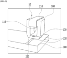
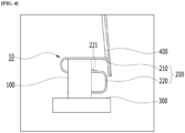
FIG. 3 is a view illustrating coupling between the electricalmember contact device 10 according to an embodiment of the present disclosure and thesubstrate 300,FIG. 4 is a side view ofFIG. 3 , andFIG. 5 is a perspective view of thegasket 100 of the present disclosure. - Referring to
FIGS. 3 to 5 , the electricalmember contact device 10 includes thegasket 100 and theframe 200. - The
gasket 100 is provided in a rectangular parallelepiped shape, has an arched lower portion to form the outer shape of the electricalmember contact device 10, and is made of a conductive material. - The
gasket 100 has afirst surface 101, asecond surface 102, a third surface 113, a fourth surface 114, and afastening hole 110 formed therethrough. - The
first surface 101 constitutes the outer surface of thegasket 100, is located at the top of thegasket 100, and has a flat cross-section. - The
second surface 102 constitutes the outer surface of thegasket 100 and is formed at a position opposite to thefirst surface 101. - The
second surface 102 is provided so that the lower portion of thegasket 100 is arched before thegasket 100 is installed on (contacts) thesubstrate 300. - In the process of installing the
gasket 100 on thesubstrate 300, the arch structure of thesecond surface 102 is pressed and comes into surface contact with thesubstrate 300. - The
gasket 100 may be made of an elastic material. Accordingly, when thegasket 100 is brought into contact with thesubstrate 300 for electrical connection, since thesecond surface 102 is deformed by elasticity while contacting thesubstrate 300, thegasket 100 and thesubstrate 300 may be brought into surface contact with each other. - The
fastening hole 110 is formed through thegasket 100 and is configured to be coupled to asupport part 220 of theframe 200 to be described below. - The third surface 113 and the fourth surface 114 form the inner surface of the
fastening hole 110. The third surface 113 is located adjacent to thefirst surface 101 and may be formed to be flat. The fourth surface 114 faces the third surface 113 and is formed adjacent to thesecond surface 102. - The
gasket 100 is electrically connected to thesubstrate 300. In such a case, thesecond surface 102 of thegasket 100 may be electrically connected by partially contacting thesubstrate 300 as described above. - When the
gasket 100 is brought into surface contact with thesubstrate 300 and is electrically connected thereto, since the contact area is larger than in the case of the related art in which thegasket 100 and thesubstrate 300 are in point contact with each other, the antenna operation may be more stable even though external shock or vibration is applied to the embodiment of the present disclosure. - When the electrical
member contact device 10 according to an embodiment of the present disclosure is installed on thesubstrate 300, no feeding pad is required unlike the related art. Since thesecond surface 102 having the arcuate structure and formed on thegasket 100 is pressed and makes surface contact while being mounted on thesubstrate 300, electrical connection can be made without a feeding pad. When a feeding pad is provided in order to electrically connect thesubstrate 300 and thegasket 100, a surface mounter technology (SMT) process needs be performed in order to mount the electricalmember contact device 10 on the surface of thesubstrate 300 during the manufacturing process, thereby increasing the manufacturing cost. However, since the SMT process can be omitted in the present disclosure, the manufacturing cost of the present disclosure can be reduced. - The
frame 200 is made of the same material as theradiator 400. Theframe 200 has conductivity. In addition, theframe 200 may be made of an elastic material. - The
frame 200 is curved past thefirst surface 101 being an upper part of thegasket 100, is formed to face thefastening hole 110, and is coupled to thegasket 100. - In addition, the
frame 200 is curved past thefirst surface 101 being the upper part of thegasket 100, and protrudes out of thefastening hole 110 by penetrating thefastening hole 110, and the protrudinggasket 100 is curved again and its end is fixed to thegasket 100. In such a case, theframe 200 may be formed in an 'S' shape when viewed from the side. - Specifically, the
frame 200 includes acontact part 210 and thesupport part 220. - The
contact part 210 is formed to surround thefirst surface 101 and the third surface 113. When viewed from the side, thecontact part 210 may be formed in a 'C' shape. - When the electrical
member contact device 10 being an embodiment of the present disclosure is used in the antenna module, thecontact part 210 is in contact with thefirst surface 101 of thegasket 100 as illustrated inFIG. 2 . The portion of thecontact part 210 that is in contact with thefirst surface 101 is formed to be flat like thefirst surface 101 and is in close contact with thefirst surface 101, thereby forming a large contact area. - In such a case, the
contact part 210 contacts the third surface 113. The portion of thecontact part 210 that is in contact with the third surface 113 is formed to be flat like the third surface 113 and is in close contact with the third surface 113. Therefore, the contact area between thecontact part 210 of theframe 200 and the third surface 113 may be formed to be large. - That is, the
contact part 210 formed in a 'C' shape may be inserted into thegasket 100 while surrounding thefirst surface 101 and the third surface 113. - The
contact part 210 may be electrically connected to theradiator 400 fixed to thecarrier 600. - The
support part 220 is electrically connected to thecontact part 210 and supports the inner surface of thefastening hole 110. - The
support part 220 is electrically connected to thecontact part 210, is arranged between the third surface 113 and the fourth surface 114 of thefastening hole 110, and is curved to protrude out of thefastening hole 110. When viewed from the side, thesupport part 220 is formed in a 'C' shape. - The
frame 200 includes aprotrusion 221. - The
protrusion 221 is formed to protrude into contact with the side surface of thegasket 100 in order to fix theframe 200. A more detailed description of theprotrusion 221 is provided below. - The
support part 220, which is formed by being curved, exerts a supporting force or an elastic force toward the third surface 113 and the fourth surface 114. Accordingly, even though thesupport part 220 is inserted into thefastening hole 110 of thegasket 100, thesupport part 220 may not be easily separated from thegasket 100 due to the supporting force or the elastic force. - The
frame 200 may be configured in an 'S' shape by electrically connecting and coupling thecontact part 210 having a 'C' shape and thesupport part 220 having a 'C' shape described above. - The
gasket 100 includes afitting guide part 130 provided in the direction penetrating thefastening hole 110 so that the end of theframe 200 is fixed by fitting into thegasket 100. - Specifically, the
fitting guide part 130 is formed on the inner surface of thefastening hole 110. Thefitting guide part 130 is located adjacent to the fourth surface 114 of thefastening hole 110, and is formed on both sides of the inner surface of thefastening hole 110 in correspondence with the shape of thesupport part 220 so that thesupport part 220 is fitted. - Since the
support part 220 is coupled to thefitting guide part 130, thesupport part 220 may not be easily separated from thegasket 100 even though external shock or the like is applied to the embodiment of the present disclosure. Therefore, the stability of the antenna operation can be maintained. -
FIG. 6 is a perspective view of the electricalmember contact device 10 according to an embodiment of the present disclosure when viewed in another direction, andFIG. 7 is a side conceptual view of the operation of theframe 200 inFIG. 6 . - Referring to
FIGS. 6 and7 , thesupport part 220 includes theprotrusion 221. - The
protrusion 221 protrudes from thesupport part 220 and contacts the side surface of thegasket 100. Therefore, theprotrusion 221 can prevent thesupport part 220 from being separated from thegasket 100. - According to the illustrated embodiment, the
protrusion 221 may be formed by cutting a portion of thesupport part 220 adjacent to the third surface 113 of thefastening hole 110 in the longitudinal direction and lifting the cut portion toward thefirst surface 101. - When the
contact part 210 having a 'C' shape is inserted into thegasket 100, theprotrusion 221 is formed in a direction opposite to the curved shape of thecontact part 210. That is, theprotrusion 221 is formed in a direction opposite to the position where thecontact part 210 surrounds thefirst surface 101 and the third surface 113. - When an embodiment of the present disclosure is used for a long period of time, since the restoring force of the
frame 200 made of an elastic material is reduced or the rigidity of theframe 200 is weakened, theframe 200 and thegasket 100 may not be closely coupled and a gap may be formed therebetween. When the gap is formed in this way, since the electrical connection between theframe 200 and thegasket 100 is unstable, there is a problem in that the antenna operation is unstable. The above-mentionedprotrusion 221 can prevent thesupport part 220 of the frame from being separated from thegasket 100. - That is, since the
frame 200 is formed in an 'S' shape by connecting thecontact part 210 and thesupport part 220 and is fastened to thegasket 100, it is difficult for theframe 200 to be separated from thegasket 100. In addition, theframe 200 has a structure in which thecontact part 210 is fitted in close contact with thegasket 100 while contacting thefirst surface 101 of thegasket 100 and the inner surface of thefastening hole 110. Moreover, thesupport part 220 is provided with theprotrusion 221 that contacts the side of thegasket 100, and thegasket 100 is provided with thefitting guide part 130 so that thesupport part 220 is fitted and coupled to thegasket 100. Accordingly, it can be seen that a plurality of means are provided to prevent theframe 200 connected to theradiator 400 from being separated from thegasket 100. - The embodiment of the present disclosure also has the effect of being able to be manufactured at low cost than before even though a plurality of methods are provided to prevent the
frame 200 connected to theradiator 400 from being separated from thegasket 100. - When the electrical
member contact device 10 being an embodiment of the present disclosure is fixed to the fixingpart 500 of the antenna module and connected to thesubstrate 300 and theradiator 400, thecontact part 210 of theframe 200 is in contact with thegasket 100, but a gap may be formed between thegasket 100 and theframe 200 before the electricalmember contact device 10 is installed in the antenna module. - Since the
frame 200 is made of an elastic material, when pressure is applied from above theframe 200 toward theframe 200, thegasket 100 and theframe 200 can be brought into close contact without a gap. - When pressure is applied from above the
frame 200 toward theframe 200, since theframe 200 is made of an elastic material, a gap may be formed between theframe 200 and the third surface 113. Even though a gap is formed between theframe 200 and the third surface 113 in this way, theframe 200 is provided with theprotrusion 221 as described above, thereby preventing theframe 200 from being separated from thegasket 100. - The above description is merely a description of the technical spirit of the present disclosure, and those skilled in the art may change and modify the present disclosure in various ways without departing from the essential characteristic of the present disclosure. Accordingly, the embodiments described in the present disclosure should not be construed as limiting the technical spirit of the present disclosure, but should be construed as describing the technical spirit of the present disclosure. The technical spirit of the present disclosure is not restricted by the embodiments. The range of protection of the present disclosure should be construed based on the following claims, and all of technical spirits within an equivalent range of the present disclosure should be construed as being included in the scope of rights of the present disclosure.
Claims (11)
- An electrical member contact device comprising:a gasket comprising a fastening hole formed therethrough and having conductivity; anda frame fastened to the fastening hole of the gasket and having conductivity,wherein the frame is curved past a first surface being an upper part of the gasket, is formed to face the fastening hole, and is coupled to the gasket.
- The electrical member contact device of claim 1, wherein the frame is curved past the first surface being the upper part of the gasket, protrudes out of the fastening hole by penetrating the fastening hole, and is curved again so that an end of the frame is fixed to the gasket.
- The electrical member contact device of claim 1, wherein the frame is formed in an 'S' shape.
- The electrical member contact device of claim 1, wherein the frame is made of an elastic material.
- The electrical member contact device of claim 1, wherein the gasket is made of an elastic material.
- The electrical member contact device of claim 2, wherein the gasket comprises a fitting guide part provided in a direction penetrating the fastening hole so that the end of the frame is fixed by fitting into the gasket.
- The electrical member contact device of claim 2, wherein the frame comprises a protrusion formed to protrude into contact with a side surface of the gasket in order to fix the frame.
- The electrical member contact device of claim 1, wherein the gasket comprises a second surface located facing the first surface and provided to be electrically conductive in contact with a substrate.
- The electrical member contact device of claim 8, wherein the fastening hole comprises:a third surface formed on an inner surface of the fastening hole and adjacent to the first surface; anda fourth surface formed on the inner surface of the fastening hole, facing the third surface, and adjacent to the second surface.
- The electrical member contact device of claim 9, wherein the frame comprises:a contact part formed in a 'C' shape while surrounding the first surface and the third surface; anda support part electrically connected to the contact part, arranged between the third surface and the fourth surface, and formed in a 'C' shape to form a curve protruding out of the fastening hole, an end of the support part being fixed to the gasket.
- The electrical member contact device of claim 10, wherein the contact part is connected to the support part in a region where the third surface is arranged.
Applications Claiming Priority (2)
| Application Number | Priority Date | Filing Date | Title |
|---|---|---|---|
| KR1020220012367A KR102656046B1 (en) | 2022-01-27 | 2022-01-27 | Electrical member contact apparatus and antenna module including the same |
| PCT/KR2023/000416 WO2023146162A1 (en) | 2022-01-27 | 2023-01-10 | Electrical member contact device and antenna module comprising same |
Publications (2)
| Publication Number | Publication Date |
|---|---|
| EP4471979A1 true EP4471979A1 (en) | 2024-12-04 |
| EP4471979A4 EP4471979A4 (en) | 2025-05-07 |
Family
ID=87471822
Family Applications (1)
| Application Number | Title | Priority Date | Filing Date |
|---|---|---|---|
| EP23747205.5A Pending EP4471979A4 (en) | 2022-01-27 | 2023-01-10 | Electrical member contact device and antenna module comprising same |
Country Status (5)
| Country | Link |
|---|---|
| US (1) | US20250112352A1 (en) |
| EP (1) | EP4471979A4 (en) |
| KR (1) | KR102656046B1 (en) |
| CN (1) | CN118891786A (en) |
| WO (1) | WO2023146162A1 (en) |
Family Cites Families (9)
| Publication number | Priority date | Publication date | Assignee | Title |
|---|---|---|---|---|
| AU7281698A (en) * | 1997-05-06 | 1998-11-27 | Gryphics, Inc. | Multi-mode compliant connector and replaceable chip module utilizing the same |
| KR100989547B1 (en) * | 2008-05-19 | 2010-10-25 | 박진우 | Antenna connection device |
| KR200458069Y1 (en) | 2010-03-16 | 2012-01-18 | 주식회사 이엠따블유 | Antenna carrier, antenna radiator, and built-in antenna having the same |
| KR101049545B1 (en) * | 2010-07-07 | 2011-07-14 | 강태석 | Antenna connection device |
| KR101123423B1 (en) * | 2010-09-03 | 2012-03-23 | 김연수 | Antanna contacting apparatus for mobile phone |
| KR101033193B1 (en) * | 2010-10-14 | 2011-05-06 | 주식회사 이노칩테크놀로지 | Electromagnetic shielding gasket |
| JP2016208291A (en) * | 2015-04-23 | 2016-12-08 | ミツミ電機株式会社 | Antenna device |
| US11258163B2 (en) * | 2018-08-30 | 2022-02-22 | Apple Inc. | Housing and antenna architecture for mobile device |
| KR102340421B1 (en) * | 2019-06-12 | 2021-12-17 | 조인셋 주식회사 | Electric conductive gasket with assembly strength improved |
-
2022
- 2022-01-27 KR KR1020220012367A patent/KR102656046B1/en active Active
-
2023
- 2023-01-10 CN CN202380026938.8A patent/CN118891786A/en active Pending
- 2023-01-10 EP EP23747205.5A patent/EP4471979A4/en active Pending
- 2023-01-10 WO PCT/KR2023/000416 patent/WO2023146162A1/en not_active Ceased
- 2023-01-10 US US18/833,813 patent/US20250112352A1/en active Pending
Also Published As
| Publication number | Publication date |
|---|---|
| KR102656046B1 (en) | 2024-04-09 |
| WO2023146162A1 (en) | 2023-08-03 |
| US20250112352A1 (en) | 2025-04-03 |
| EP4471979A4 (en) | 2025-05-07 |
| KR20230115651A (en) | 2023-08-03 |
| CN118891786A (en) | 2024-11-01 |
Similar Documents
| Publication | Publication Date | Title |
|---|---|---|
| US8026864B2 (en) | Antenna device, antenna element and antenna module | |
| EP1861893B1 (en) | Patch antenna with electromagnetic shield counterpoise | |
| US12199332B2 (en) | Antenna device for vehicle | |
| US10008768B2 (en) | Capacitively shielded housing, in particular capacitively shielded component housing for an antenna device | |
| KR101814301B1 (en) | Multiband vehicular antenna assemblies | |
| CN103918126A (en) | GPS antenna on-shield/housing with grounding | |
| CN113839222B (en) | Antenna device | |
| US7078620B2 (en) | Mounting structure of on-vehicle electronic circuit unit | |
| KR20050043701A (en) | Multi-frequency antenna | |
| KR101153165B1 (en) | High frequency transmission line using printed circuit board | |
| EP4471979A1 (en) | Electrical member contact device and antenna module comprising same | |
| US7646350B2 (en) | Antenna structure | |
| CN108565552B (en) | Antenna device, connection structure and terminal equipment | |
| US20040075612A1 (en) | Antenna device | |
| KR102278616B1 (en) | Antenna device and vehicle having the same | |
| US20220376382A1 (en) | Antenna module for small device | |
| US20110075375A1 (en) | Tuner module capable of preventing a heat conductive sheet from arising | |
| CN220527199U (en) | Flat dual-frequency patch antenna | |
| US6735308B1 (en) | Mobile telephone connector module | |
| US12327912B2 (en) | Vehicle antenna module | |
| US6940459B2 (en) | Antenna assembly with electrical connectors | |
| KR20170084794A (en) | Antenna Module | |
| US8681054B2 (en) | PIFA/monopole hybrid antenna and mobile communications device having the same | |
| WO2001091228A1 (en) | Antenna arrangement | |
| KR102278617B1 (en) | Antenna device and vehicle having the same |
Legal Events
| Date | Code | Title | Description |
|---|---|---|---|
| STAA | Information on the status of an ep patent application or granted ep patent |
Free format text: STATUS: THE INTERNATIONAL PUBLICATION HAS BEEN MADE |
|
| PUAI | Public reference made under article 153(3) epc to a published international application that has entered the european phase |
Free format text: ORIGINAL CODE: 0009012 |
|
| STAA | Information on the status of an ep patent application or granted ep patent |
Free format text: STATUS: REQUEST FOR EXAMINATION WAS MADE |
|
| 17P | Request for examination filed |
Effective date: 20240806 |
|
| AK | Designated contracting states |
Kind code of ref document: A1 Designated state(s): AL AT BE BG CH CY CZ DE DK EE ES FI FR GB GR HR HU IE IS IT LI LT LU LV MC ME MK MT NL NO PL PT RO RS SE SI SK SM TR |
|
| DAV | Request for validation of the european patent (deleted) | ||
| DAX | Request for extension of the european patent (deleted) | ||
| A4 | Supplementary search report drawn up and despatched |
Effective date: 20250403 |
|
| RIC1 | Information provided on ipc code assigned before grant |
Ipc: H01R 13/24 20060101ALI20250328BHEP Ipc: H01R 12/71 20110101ALI20250328BHEP Ipc: H01R 12/70 20110101ALI20250328BHEP Ipc: H01Q 1/00 20060101ALI20250328BHEP Ipc: H01Q 1/20 20060101AFI20250328BHEP |