EP4471953A2 - Battery box and electric equipment - Google Patents
Battery box and electric equipment Download PDFInfo
- Publication number
- EP4471953A2 EP4471953A2 EP24166632.0A EP24166632A EP4471953A2 EP 4471953 A2 EP4471953 A2 EP 4471953A2 EP 24166632 A EP24166632 A EP 24166632A EP 4471953 A2 EP4471953 A2 EP 4471953A2
- Authority
- EP
- European Patent Office
- Prior art keywords
- beams
- reinforcement
- battery
- battery box
- module
- Prior art date
- Legal status (The legal status is an assumption and is not a legal conclusion. Google has not performed a legal analysis and makes no representation as to the accuracy of the status listed.)
- Granted
Links
Images



Classifications
-
- H—ELECTRICITY
- H01—ELECTRIC ELEMENTS
- H01M—PROCESSES OR MEANS, e.g. BATTERIES, FOR THE DIRECT CONVERSION OF CHEMICAL ENERGY INTO ELECTRICAL ENERGY
- H01M50/00—Constructional details or processes of manufacture of the non-active parts of electrochemical cells other than fuel cells, e.g. hybrid cells
- H01M50/20—Mountings; Secondary casings or frames; Racks, modules or packs; Suspension devices; Shock absorbers; Transport or carrying devices; Holders
- H01M50/204—Racks, modules or packs for multiple batteries or multiple cells
- H01M50/207—Racks, modules or packs for multiple batteries or multiple cells characterised by their shape
- H01M50/213—Racks, modules or packs for multiple batteries or multiple cells characterised by their shape adapted for cells having curved cross-section, e.g. round or elliptic
-
- B—PERFORMING OPERATIONS; TRANSPORTING
- B60—VEHICLES IN GENERAL
- B60L—PROPULSION OF ELECTRICALLY-PROPELLED VEHICLES; SUPPLYING ELECTRIC POWER FOR AUXILIARY EQUIPMENT OF ELECTRICALLY-PROPELLED VEHICLES; ELECTRODYNAMIC BRAKE SYSTEMS FOR VEHICLES IN GENERAL; MAGNETIC SUSPENSION OR LEVITATION FOR VEHICLES; MONITORING OPERATING VARIABLES OF ELECTRICALLY-PROPELLED VEHICLES; ELECTRIC SAFETY DEVICES FOR ELECTRICALLY-PROPELLED VEHICLES
- B60L3/00—Electric devices on electrically-propelled vehicles for safety purposes; Monitoring operating variables, e.g. speed, deceleration or energy consumption
- B60L3/0007—Measures or means for preventing or attenuating collisions
-
- B—PERFORMING OPERATIONS; TRANSPORTING
- B60—VEHICLES IN GENERAL
- B60L—PROPULSION OF ELECTRICALLY-PROPELLED VEHICLES; SUPPLYING ELECTRIC POWER FOR AUXILIARY EQUIPMENT OF ELECTRICALLY-PROPELLED VEHICLES; ELECTRODYNAMIC BRAKE SYSTEMS FOR VEHICLES IN GENERAL; MAGNETIC SUSPENSION OR LEVITATION FOR VEHICLES; MONITORING OPERATING VARIABLES OF ELECTRICALLY-PROPELLED VEHICLES; ELECTRIC SAFETY DEVICES FOR ELECTRICALLY-PROPELLED VEHICLES
- B60L50/00—Electric propulsion with power supplied within the vehicle
- B60L50/50—Electric propulsion with power supplied within the vehicle using propulsion power supplied by batteries or fuel cells
- B60L50/60—Electric propulsion with power supplied within the vehicle using propulsion power supplied by batteries or fuel cells using power supplied by batteries
- B60L50/64—Constructional details of batteries specially adapted for electric vehicles
-
- H—ELECTRICITY
- H01—ELECTRIC ELEMENTS
- H01M—PROCESSES OR MEANS, e.g. BATTERIES, FOR THE DIRECT CONVERSION OF CHEMICAL ENERGY INTO ELECTRICAL ENERGY
- H01M50/00—Constructional details or processes of manufacture of the non-active parts of electrochemical cells other than fuel cells, e.g. hybrid cells
- H01M50/20—Mountings; Secondary casings or frames; Racks, modules or packs; Suspension devices; Shock absorbers; Transport or carrying devices; Holders
- H01M50/204—Racks, modules or packs for multiple batteries or multiple cells
-
- H—ELECTRICITY
- H01—ELECTRIC ELEMENTS
- H01M—PROCESSES OR MEANS, e.g. BATTERIES, FOR THE DIRECT CONVERSION OF CHEMICAL ENERGY INTO ELECTRICAL ENERGY
- H01M50/00—Constructional details or processes of manufacture of the non-active parts of electrochemical cells other than fuel cells, e.g. hybrid cells
- H01M50/20—Mountings; Secondary casings or frames; Racks, modules or packs; Suspension devices; Shock absorbers; Transport or carrying devices; Holders
- H01M50/244—Secondary casings; Racks; Suspension devices; Carrying devices; Holders characterised by their mounting method
-
- H—ELECTRICITY
- H01—ELECTRIC ELEMENTS
- H01M—PROCESSES OR MEANS, e.g. BATTERIES, FOR THE DIRECT CONVERSION OF CHEMICAL ENERGY INTO ELECTRICAL ENERGY
- H01M50/00—Constructional details or processes of manufacture of the non-active parts of electrochemical cells other than fuel cells, e.g. hybrid cells
- H01M50/20—Mountings; Secondary casings or frames; Racks, modules or packs; Suspension devices; Shock absorbers; Transport or carrying devices; Holders
- H01M50/249—Mountings; Secondary casings or frames; Racks, modules or packs; Suspension devices; Shock absorbers; Transport or carrying devices; Holders specially adapted for aircraft or vehicles, e.g. cars or trains
-
- H—ELECTRICITY
- H01—ELECTRIC ELEMENTS
- H01M—PROCESSES OR MEANS, e.g. BATTERIES, FOR THE DIRECT CONVERSION OF CHEMICAL ENERGY INTO ELECTRICAL ENERGY
- H01M50/00—Constructional details or processes of manufacture of the non-active parts of electrochemical cells other than fuel cells, e.g. hybrid cells
- H01M50/20—Mountings; Secondary casings or frames; Racks, modules or packs; Suspension devices; Shock absorbers; Transport or carrying devices; Holders
- H01M50/262—Mountings; Secondary casings or frames; Racks, modules or packs; Suspension devices; Shock absorbers; Transport or carrying devices; Holders with fastening means, e.g. locks
-
- H—ELECTRICITY
- H01—ELECTRIC ELEMENTS
- H01M—PROCESSES OR MEANS, e.g. BATTERIES, FOR THE DIRECT CONVERSION OF CHEMICAL ENERGY INTO ELECTRICAL ENERGY
- H01M50/00—Constructional details or processes of manufacture of the non-active parts of electrochemical cells other than fuel cells, e.g. hybrid cells
- H01M50/20—Mountings; Secondary casings or frames; Racks, modules or packs; Suspension devices; Shock absorbers; Transport or carrying devices; Holders
- H01M50/262—Mountings; Secondary casings or frames; Racks, modules or packs; Suspension devices; Shock absorbers; Transport or carrying devices; Holders with fastening means, e.g. locks
- H01M50/264—Mountings; Secondary casings or frames; Racks, modules or packs; Suspension devices; Shock absorbers; Transport or carrying devices; Holders with fastening means, e.g. locks for cells or batteries, e.g. straps, tie rods or peripheral frames
-
- H—ELECTRICITY
- H01—ELECTRIC ELEMENTS
- H01M—PROCESSES OR MEANS, e.g. BATTERIES, FOR THE DIRECT CONVERSION OF CHEMICAL ENERGY INTO ELECTRICAL ENERGY
- H01M50/00—Constructional details or processes of manufacture of the non-active parts of electrochemical cells other than fuel cells, e.g. hybrid cells
- H01M50/20—Mountings; Secondary casings or frames; Racks, modules or packs; Suspension devices; Shock absorbers; Transport or carrying devices; Holders
- H01M50/289—Mountings; Secondary casings or frames; Racks, modules or packs; Suspension devices; Shock absorbers; Transport or carrying devices; Holders characterised by spacing elements or positioning means within frames, racks or packs
-
- H—ELECTRICITY
- H01—ELECTRIC ELEMENTS
- H01M—PROCESSES OR MEANS, e.g. BATTERIES, FOR THE DIRECT CONVERSION OF CHEMICAL ENERGY INTO ELECTRICAL ENERGY
- H01M2220/00—Batteries for particular applications
- H01M2220/20—Batteries in motive systems, e.g. vehicle, ship, plane
-
- H—ELECTRICITY
- H01—ELECTRIC ELEMENTS
- H01M—PROCESSES OR MEANS, e.g. BATTERIES, FOR THE DIRECT CONVERSION OF CHEMICAL ENERGY INTO ELECTRICAL ENERGY
- H01M50/00—Constructional details or processes of manufacture of the non-active parts of electrochemical cells other than fuel cells, e.g. hybrid cells
- H01M50/20—Mountings; Secondary casings or frames; Racks, modules or packs; Suspension devices; Shock absorbers; Transport or carrying devices; Holders
- H01M50/233—Mountings; Secondary casings or frames; Racks, modules or packs; Suspension devices; Shock absorbers; Transport or carrying devices; Holders characterised by physical properties of casings or racks, e.g. dimensions
- H01M50/236—Hardness
-
- Y—GENERAL TAGGING OF NEW TECHNOLOGICAL DEVELOPMENTS; GENERAL TAGGING OF CROSS-SECTIONAL TECHNOLOGIES SPANNING OVER SEVERAL SECTIONS OF THE IPC; TECHNICAL SUBJECTS COVERED BY FORMER USPC CROSS-REFERENCE ART COLLECTIONS [XRACs] AND DIGESTS
- Y02—TECHNOLOGIES OR APPLICATIONS FOR MITIGATION OR ADAPTATION AGAINST CLIMATE CHANGE
- Y02E—REDUCTION OF GREENHOUSE GAS [GHG] EMISSIONS, RELATED TO ENERGY GENERATION, TRANSMISSION OR DISTRIBUTION
- Y02E60/00—Enabling technologies; Technologies with a potential or indirect contribution to GHG emissions mitigation
- Y02E60/10—Energy storage using batteries
Definitions
- the present disclosure relates to the technical field of batteries, and in particular, to a battery box and an electric equipment.
- a power battery As one of core components of an electric vehicle, a power battery is the energy hub of the electric vehicle.
- a battery box as an energy distribution unit of the power battery, plays an irreplaceable role in the entire vehicle. With the development of the power battery technology, higher requirements are put forward for the mechanical strength of the battery box.
- reinforcement beams are generally provided in the middle of the box body.
- the reinforcement beam improves the impact resistance of the battery box, improves the mechanical performance of the box body, and has a simple structure, lighter weight, and higher reliability.
- side walls of the box body still have the risk of wear and tear, thereby causing safety accidents.
- the reinforcement beams occupy a large internal space of the battery box, which has the problem of low space utilization.
- Embodiments of the present disclosure provide a battery box and an electric equipment to solve or at least partially solve the shortcomings of the above background.
- inventions of the present disclosure provide a battery box.
- the battery box includes a box body and a battery module located in the box body.
- the battery module includes a plurality of cell groups arranged at intervals along a first direction, and each cell group includes a plurality of battery cells arranged at intervals along a second direction.
- the box body includes a box frame and a reinforcement module.
- the box frame includes a bottom plate and a plurality of side beams.
- the plurality of side beams are fixedly arranged on edges of the bottom plate to define an accommodation cavity.
- the battery module and the reinforcement module are both arranged in the accommodation cavity.
- the reinforcement module includes a plurality of reinforcement beams arranged at intervals along the first direction. Both ends of the reinforcement beam are fixedly connected to the side beams.
- One cell group is provided between adjacent reinforcement beams.
- embodiments of the present disclosure provide an electrical device, which includes any one of the battery boxes described above.
- Embodiments of the present disclosure provide a battery box and an electric equipment.
- the battery box includes the box body and the battery module located in the box body.
- the battery module includes the plurality of cell groups arranged at intervals along the first direction, and each cell group includes the plurality of battery cells arranged at intervals along the second direction.
- the box body includes the box frame and the reinforcement module.
- the box frame includes the bottom plate and the plurality of side beams.
- the plurality of side beams are fixedly arranged on the edges of the bottom plate to define the accommodation cavity.
- the battery module and the reinforcement module are both arranged in the accommodation cavity.
- the reinforcement module includes the plurality of reinforcement beams arranged at intervals along the first direction. Both ends of the reinforcement beam are fixedly connected to the side beams.
- One cell group is provided between adjacent reinforcement beams.
- the embodiments provide a battery box and an electric equipment. Each is explained in detail below. It should be noted that the order of description of the following embodiments does not limit the preferred order of the embodiments.
- the embodiments provide a battery box and an electric equipment.
- the battery box includes a box body 10 and a battery module (not shown in the figures) located in the box body 10.
- the battery module includes a plurality of cell groups arranged at intervals along a first direction X. Each cell group includes a plurality of battery cells arranged at intervals along a second direction Y.
- the box body 10 includes a box frame 11 and a reinforcement module 14.
- the box frame 11 includes a bottom plate 12 and a plurality of side beams 11A. The plurality of side beams 11A are fixedly arranged on edges of the bottom plate to define an accommodation cavity 100.
- the battery module and the reinforcement module 14 are both arranged in the accommodation cavity 100.
- the reinforcement module 14 includes a plurality of reinforcement beams 14A arranged at intervals along the first direction X. Both ends of the reinforcement beam 14A are fixedly connected to the side beams 11A. One cell group is provided between every adjacent two of the reinforcement beams 14A.
- the reinforcement beams are generally provided in the middle of the box body.
- the reinforcement beam improves the impact resistance of the battery box, improves the mechanical performance of the box body, and has a simple structure, lighter weight, and higher reliability.
- side walls of the box body still have the risk of wear and tear, thereby causing safety accidents.
- the reinforcement beams occupy a large internal space of the battery box, which has the problem of low space utilization.
- the box body includes the reinforcement module, and the reinforcement module includes the plurality of reinforcement beams arranged at intervals along the first direction. Both ends of each reinforcement beam are fixedly connected to the side beams, and one cell group is provided between every adjacent reinforcement beams, thereby achieving a high-strength design while meeting the hardness requirements of the battery box. Furthermore, the reinforcement beam is arranged between adjacent cell groups, so that the space utilization of the battery box is increased.
- FIG. 1 is a schematic structural view of the box body provided by an embodiment of the present disclosure
- FIG. 2 is an exploded view of the box body provided by the embodiment of the present disclosure
- FIG. 3 is a top view of the box body provided by the embodiment of the present disclosure.
- the battery box includes a box body 10 and a battery module located in the box body 10.
- the box body 10 includes a box frame 11 and a reinforcement module 14.
- the box frame 11 includes a bottom plate 12, a support plate 13, and a plurality of side beams 11A.
- the support plate 13 is located between the bottom plate 12 and the reinforcement module 14.
- the support plate 13 is fixedly connected to the reinforcement module 14 and the bottom plate 12.
- the plurality of the side beams 11A are fixedly arranged on edges of the bottom plate 12 to define an accommodation cavity 100.
- the battery module and the reinforcement module 14 are both arranged in the accommodation cavity 100.
- the box frame 11 further includes a cross beam 11B.
- the plurality of side beams 11A are connected in sequence to form an annular structure. Both ends of the cross beam 11B are in contact with the side beams 11A, so that the cross beam 11B and the plurality of side beams 11A form the accommodation cavity 100 for placing the battery module.
- the battery module and the reinforcement module 14 are both disposed in the accommodation cavity 100.
- the reinforcement module 14 includes a plurality of reinforcement beams 14A arranged at intervals along the first direction X. Both ends of the reinforcement beam 14A are fixedly connected to the side beams 11A.
- the cell groups are arranged between adjacent reinforcement beams 14A. Furthermore, in the embodiment, two cell groups are located between every two adjacent reinforcement beams 14A.
- the reinforcement beam 14A abuts against outer peripheral surfaces of the battery cells located on its both sides, and the reinforcement beam 14A matches the outer peripheral surface of the battery cell.
- the first direction is marked with X
- the second direction is marked with Y
- the first direction X and the second direction Y are arranged at a right angle.
- the battery cells are cylindrical battery cells, and the battery module includes a plurality of cylindrical battery cells. Multiple cylindrical battery cells are provided between adjacent reinforcement beams 14A.
- the reinforcement beam 14A has a corrugated structure matching the outer peripheral surface of the cylindrical battery cell.
- a thickness of the reinforcement beam 14A is greater than or equal to 1 mm and less than or equal to 4 mm.
- the thickness of the reinforcement beam 14A is one of 1 mm, 2 mm, 3 mm, and 4 mm.
- the reinforcement beam 14A is arranged to contact the outer peripheral surfaces of the battery cells located on its both sides, and the reinforcement beam 14A matches the outer peripheral surface of the battery cell, so that a structure of the reinforcement beam 14A is added to a gap between adjacent cell groups to increase the space utilization of the battery box. Furthermore, the reinforcement beams 14A are evenly distributed, which may effectively disperse the force, reduce stress concentration, and enhance the strength of the battery box.
- FIG. 4 is a schematic structural view of the box frame provided by an embodiment of the present disclosure
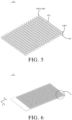
- FIG. 5 is a schematic structural view of the reinforcement module provided by an embodiment of the present disclosure.
- a plurality of recesses 11C are provided on sides of the side beams 11A close to the reinforcement beams 14A
- plug-in parts 14B are provided on sides of the reinforcement beams 14A close to the side beams 11A
- one plug-in part 14B is plugged in a corresponding one recess 11C
- the plug-in part 14B and the recess 11C are fixed by welding.
- the plurality of plug-in parts 14B are provided on sides of the side beams 11A close to the reinforcement beams 14A
- the recesses 11C are provided on sides of the reinforcement beams 14A close to the side beams 11A
- one plug-in part 14B is plugged in a corresponding one recess 11C
- the plug-in part 14B and the recess 11C are fixed by welding.
- the side beams 11A include a first side beam 11A1 and a second side beam 11A2 arranged oppositely. One end of the cross beam 11B is in contact with the first side beam 11A1, and the other end of the cross beam 11B is in contact with the second side beam 11A2.
- the reinforcement beams 14A are located between the first side beam 11A1 and the second side beam 11A2. An extending direction of the reinforcement beam 14A is parallel to an extending direction of the cross beam 11B.
- the first side beam 11A1 is provided with a plurality of first recesses 11C1 on a side close to the reinforcement module 14, and the second side beam 11A2 is provided with a plurality of second recesses 11C2 on a side close to the reinforcement module 14.
- One first recess 11C1 is provided corresponding to one second recess 11C2.
- the reinforcement beam 14A is located between the first recess 11C1 and the second recess 11C2.
- Each reinforcement beam 14A includes a first plug-in part 14B1 and a second plug-in part 14B2.
- the reinforcement beam 14A is plugged in the first recess 11C1 through the first plug-in part 14B1, and the reinforcement beam 14A is plugged in the second recess 11C2 through the second plug-in part 14B2.
- the first plug-in part 14B1 and the first recess 11C1 are fixed by welding.
- the second plug-in part 14B2 and the second recess 11C2 are fixed by welding.
- the reinforcement beam 14A is plugged in the first recess 11C1 through the first plug-in part 14B1, and the reinforcement beam 14A is plugged in the second recess 11C2 through the second plug-in part 14B2, thereby improving the assembly efficiency when assembling the reinforcement beams 14A and increasing the production capacity of the battery box.
- the first plug-in part 14B 1 and the first recess 11C1 are fixed by welding
- the second plug-in part 14B2 and the second recess 11C2 are fixed by welding
- the first recess 11C1 and the second recess 11C2 are configured to limit the reinforcement beam 14A, which may prevent the reinforcement beam 14A from moving when the battery box is subjected to external impact, thereby improving the stability of the battery box.
- the embodiment does not specifically limit positions of the recess 11C and the plug-in part 14B.
- the embodiment illustrates the technical solution of the present disclosure by only taking an example that the plurality of recesses 11C provided on sides of the side beams 11A close to the reinforcement beams 14A and the plug-in parts 14B are provided on sides of the reinforcement beams 14A close to the side beams 11A.
- the battery box further includes two longitudinal beams 11D arranged oppositely along the second direction Y.
- the longitudinal beams 11D are located on sides of the side beams 11A facing away from the reinforcement beams 14A.
- Each longitudinal beam 11D is provided with a plurality of mounting points 11E arranged at intervals along the first direction X.
- the reinforcement beams 14A are located between the two longitudinal beams 11D, and the mounting points 11E correspond to the reinforcement beams 14A one by one.
- the mounting points 11E are configured to connect to mounting portions of a vehicle body to install the battery box on the vehicle body.
- the longitudinal beams 11D include a first longitudinal beam 11D1 and a second longitudinal beam 11D2 arranged oppositely along the second direction Y.
- the first longitudinal beam 11D1 is located on one side of the first side beam 11A1 facing away from the reinforcement beams 14A
- the second longitudinal beam 11D2 is located on one side of the second side beam 11A2 facing away from the reinforcement beams 14A.
- the first longitudinal beam 11D1 is provided with a plurality of first mounting points 11E1 arranged at intervals along the first direction X.
- the second longitudinal beam 11D2 is provided with a plurality of second mounting points 11E2 arranged at intervals along the first direction X.
- One first mounting point 11E1 is arranged corresponding to one second mount point 11E2.
- the reinforcement beams 14A are located between the first longitudinal beam 11D1 and the second longitudinal beam 11D2.
- the extending direction of the reinforcement beam 14A is consistent with a direction of force transmission on the mounting points 11E to strengthen the load bearing capacity of the mounting points 11E, thereby further enhancing the mounting strength of the entire battery box.
- first longitudinal beam 11D1 and the first side beam 11A1 may be integrally formed, and the second longitudinal beam 11D2 and the second side beam 11A2 may be integrally formed, so that the structural strength of the mounting points 11E is further enhanced and the structural stability of the entire battery box is enhanced.
- FIG. 6 is a schematic structural view of the support plate provided by an embodiment of the present disclosure
- FIG. 7 is an enlarged schematic view of part A in FIG. 6
- FIG. 8 is a schematic structural view of the bottom plate provided by an embodiment of the present disclosure.
- the support plate 13 is provided with a plurality of installation slots 13A.
- Each installation slot 13A penetrates the support plate 13.
- the installation slots 13A and the reinforcement beams 14A are arranged at intervals.
- One battery cell is correspondingly installed in one installation slot 13A.
- one battery cell is correspondingly arranged and installed in one installation slot 13A, so that multiple battery cells may be installed simultaneously during assembly, which greatly improves the assembly efficiency of the battery module, ensures assembly accuracy, and is easy to realize automation.
- a structural glue may be used to fixedly connect the support plate 13 to the battery cells, making the connection convenient and reliable, and effectively preventing the battery cells from loosening and falling off.
- the adjacent installation slots 13A are arranged side by side or in a staggered manner.
- a shape of the installation slot 13A includes but is not limited to any one or more combinations of rhombus, circle, and regular hexagon.
- the shape of the installation slot 13A is a rhombus
- more and denser openings may be provided to minimize the Young's modulus of the support plate 13.
- the stability of the circle may be used to alleviate the stress when the support plate 13 is bent.
- the shape of the installation slot 13A is a regular hexagon, which is similar to a honeycomb shape, the strength of a bending area may be supplemented when the support plate 13 is bent, and the fracture damage of the support plate 13 may be avoided.
- aperture sizes of the plurality of installation slots 13A are equal, and the adjacent installation slots 13A are disposed in a staggered manner. It can be understood that the misaligned installation slots 13A may reduce the bending stress of the support plate 13 when the support plate 13 is bent under force, thereby avoiding adverse phenomena such as bending of the support plate 13 under the force.
- one of the support plate 13 and the reinforcement beam 14A provided with fixing holes 13B, and the other one of the support plate 13 and the reinforcement beam 14A is provided with protrusions 14C.
- One protrusions 14C is provided corresponding to one fixing hole 13B, and the protrusion 14C is clamped in the fixing hole 13B.
- the support plate 13 is provided with the plurality of fixing holes 13B, and each fixing hole 13B penetrates the support plate 13.
- Sides of the reinforcement beams 14A close to the support plate 13 are provided with the plurality of protrusions 14C.
- One protrusion 14C is provided corresponding to one fixing hole 13B.
- the protrusions 14C are clamped in the fixing holes 13B, and the protrusions 14C are fixedly to the support plate 13 by welding.
- the protrusions 14C of the reinforcement beams 14A and the support plate 13 are fixed by spot welding, and welding points are located on one side of the support plate 13 close to the bottom plate 12.
- the plurality of installation slots 13A are provided on the support plate 13, and the installation slots 13A may reduce the rigidity of the support plate 13.
- the protrusions 14C of the reinforcement beams 14A and the support plate 13 are fixed by spot welding, thereby increasing the rigidity of the support plate 13 and improving the stability of the battery box.
- the fixing holes 13B and the installation slots 13A are arranged at intervals.
- An aperture of the fixing hole 13B is less than an aperture of the installation slot 13A.
- One protrusion 14C is provided corresponding to one fixing hole 13B. The protrusion 14C passes through the fixing hole 13B fixed to the support plate 13 by welding, and the welding point is located on one side of the support plate 13 facing away from the reinforcement beams 14A.
- the support plate 13 is provided with the plurality of fixing holes 13B, sides of the reinforcement beams 14A close to the support plate 13 are provided with the plurality of protrusions 14C, the protrusions 14C are clamped in the fixing holes 13B, and the protrusions 14C and the support plate 13 are fixed by welding, so that the fixing strength between the reinforcement beams 14A and the support plate 13 is enhanced, thereby increasing the structural strength of the battery box.
- the support plate 13 may provide a certain supporting force to the battery module, thereby effectively improving the installation stability of the battery module and further improving the protection effect of the battery box on the battery module.
- a plurality of openings 13C are provided on the support plate 13.
- the bottom plate 12 is provided with a plurality of connection holes 12A.
- One connection hole 12A is provided corresponding to one opening 13C.
- the battery box includes a plurality of fixing members 15.
- One fixing member 15 is arranged corresponding to one opening 13C. The fixing member 15 passes through the opening 13C and the connection hole 12A in sequence to be fixedly connected to the bottom plate 12. Specifically, the fixing member 15 is threadedly connected to the bottom plate 12 through the opening 13C, and the support plate 13 is fixedly connected to the bottom plate 12 through the fixing member 15.
- the openings 13C and the fixing holes 13B are arranged at intervals.
- the openings 13C and the installation slots 13A are fixedly arranged.
- the fixing members 15 include but is not limited to bolts. It can be understood that in the embodiment, the fixing member 15 is threadedly connected to the bottom plate 12 through the opening 13C, and the support plate 13 is fixedly connected to the bottom plate 12 through the fixing member 15, thereby improving the structural stability of the battery box.
- the battery box further includes a liquid cooling module disposed in the accommodation cavity 100.
- the liquid cooling module includes a plurality of liquid cooling plates arranged at intervals along the first direction X.
- the plurality of liquid cooling plates and the plurality of the reinforcement beams 14A are alternately arranged along the first direction X.
- One cell group is arranged between every adjacent two of the liquid cooling plates and the reinforcement beams 14A, which facilitates heat dissipation of the battery module, improves the cooling effect of the battery box, and improves temperature uniformity.
- the embodiments also provides an electrical device, which includes the battery box described in any of the above embodiments.
- the battery box includes the battery module, and the battery module is used as a power supply for the electric equipment. Therefore, the electric equipment also has various advantages of the above-mentioned battery module, which simplifies an overall structure of the electric equipment.
- the electric equipment may be a vehicle, an aircraft, or a mechanical production equipment, etc.
- Embodiments of the present disclosure provide the battery box and the electric equipment.
- the battery box includes the box body and the battery module located in the box body.
- the battery module includes the plurality of cell groups arranged at intervals along the first direction, and each cell group includes the plurality of battery cells arranged at intervals along the second direction.
- the box body includes the box frame and the reinforcement module.
- the box frame includes the bottom plate and the plurality of side beams.
- the plurality of side beams are fixedly arranged on the edges of the bottom plate to define the accommodation cavity.
- the battery module and the reinforcement module are both arranged in the accommodation cavity.
- the reinforcement module includes the plurality of reinforcement beams arranged at intervals along the first direction. Both ends of the reinforcement beam are fixedly connected to the side beams.
- One cell group is provided between adjacent reinforcement beams.
Landscapes
- Chemical & Material Sciences (AREA)
- General Chemical & Material Sciences (AREA)
- Electrochemistry (AREA)
- Chemical Kinetics & Catalysis (AREA)
- Engineering & Computer Science (AREA)
- Sustainable Energy (AREA)
- Mechanical Engineering (AREA)
- Transportation (AREA)
- Power Engineering (AREA)
- Life Sciences & Earth Sciences (AREA)
- Sustainable Development (AREA)
- Aviation & Aerospace Engineering (AREA)
- Battery Mounting, Suspending (AREA)
Abstract
Description
- The present disclosure relates to the technical field of batteries, and in particular, to a battery box and an electric equipment.
- As one of core components of an electric vehicle, a power battery is the energy hub of the electric vehicle. A battery box, as an energy distribution unit of the power battery, plays an irreplaceable role in the entire vehicle. With the development of the power battery technology, higher requirements are put forward for the mechanical strength of the battery box.
- At present, in related arts, in order to improve a side anti-collision ability of the battery box, reinforcement beams are generally provided in the middle of the box body. The reinforcement beam improves the impact resistance of the battery box, improves the mechanical performance of the box body, and has a simple structure, lighter weight, and higher reliability. However, for other positions in the battery box that are far away from the reinforcement beams, when the battery box is subjected to external impact, side walls of the box body still have the risk of wear and tear, thereby causing safety accidents. At the same time, in the related arts, the reinforcement beams occupy a large internal space of the battery box, which has the problem of low space utilization.
- Embodiments of the present disclosure provide a battery box and an electric equipment to solve or at least partially solve the shortcomings of the above background.
- In a first aspect, embodiments of the present disclosure provide a battery box. The battery box includes a box body and a battery module located in the box body. The battery module includes a plurality of cell groups arranged at intervals along a first direction, and each cell group includes a plurality of battery cells arranged at intervals along a second direction. The box body includes a box frame and a reinforcement module. The box frame includes a bottom plate and a plurality of side beams. The plurality of side beams are fixedly arranged on edges of the bottom plate to define an accommodation cavity. The battery module and the reinforcement module are both arranged in the accommodation cavity. The reinforcement module includes a plurality of reinforcement beams arranged at intervals along the first direction. Both ends of the reinforcement beam are fixedly connected to the side beams. One cell group is provided between adjacent reinforcement beams.
- In a second aspect, embodiments of the present disclosure provide an electrical device, which includes any one of the battery boxes described above.
- Beneficial effects of the embodiments of the present disclosure: Embodiments of the present disclosure provide a battery box and an electric equipment. The battery box includes the box body and the battery module located in the box body. The battery module includes the plurality of cell groups arranged at intervals along the first direction, and each cell group includes the plurality of battery cells arranged at intervals along the second direction. The box body includes the box frame and the reinforcement module. The box frame includes the bottom plate and the plurality of side beams. The plurality of side beams are fixedly arranged on the edges of the bottom plate to define the accommodation cavity. The battery module and the reinforcement module are both arranged in the accommodation cavity. The reinforcement module includes the plurality of reinforcement beams arranged at intervals along the first direction. Both ends of the reinforcement beam are fixedly connected to the side beams. One cell group is provided between adjacent reinforcement beams. The solutions provided by the embodiments of the present disclosure achieve a high-strength design while meeting the hardness requirements of the battery box.
- In order to explain the technical solutions in the embodiments more clearly, the drawings needed to be used in the description of the embodiments will be briefly introduced below. Obviously, the drawings in the following description are only some embodiments of the present disclosure. Those skilled in the art may also obtain other drawings based on these drawings without exerting creative efforts.
-
FIG. 1 is a schematic structural view of a box body provided by an embodiment of the present disclosure. -
FIG. 2 is an exploded view of the box body provided by the embodiment of the present disclosure. -
FIG. 3 is a top view of the box body provided by the embodiment of the present disclosure. -
FIG. 4 is a schematic structural view of a box frame provided by an embodiment of the present disclosure. -
FIG. 5 is a schematic structural view of a reinforcement module provided by an embodiment of the present disclosure. -
FIG. 6 is a schematic structural view of a support plate provided by an embodiment of the present disclosure. -
FIG. 7 is an enlarged schematic view of part A inFIG. 6 . -
FIG. 8 is a schematic structural view of a bottom plate provided by an embodiment of the present disclosure. - The technical solutions in the embodiments will be clearly and completely described below with reference to the accompanying drawings in the embodiments. Obviously, the described embodiments are only some of the embodiments of the present disclosure, rather than all of the embodiments. Based on the embodiments in the present disclosure, all other embodiments obtained by those skilled in the art without making creative efforts fall within the protection scope of the present disclosure. In addition, it should be understood that the specific embodiments described here are only used to illustrate and explain the invention, and are not intended to limit the invention. In the present disclosure, unless otherwise specified, the orientational terms such as "upper" and "lower" usually refer to the upper and lower positions of the device in actual use or working conditions, specifically the orientations in the drawings. The terms "Inside" and "outside" refer to the outline of the device.
- The embodiments provide a battery box and an electric equipment. Each is explained in detail below. It should be noted that the order of description of the following embodiments does not limit the preferred order of the embodiments.
- Referring to
FIG. 1 to FIG. 7 , the embodiments provide a battery box and an electric equipment. The battery box includes abox body 10 and a battery module (not shown in the figures) located in thebox body 10. The battery module includes a plurality of cell groups arranged at intervals along a first direction X. Each cell group includes a plurality of battery cells arranged at intervals along a second direction Y. Thebox body 10 includes abox frame 11 and areinforcement module 14. Thebox frame 11 includes abottom plate 12 and a plurality ofside beams 11A. The plurality ofside beams 11A are fixedly arranged on edges of the bottom plate to define anaccommodation cavity 100. The battery module and thereinforcement module 14 are both arranged in theaccommodation cavity 100. Thereinforcement module 14 includes a plurality ofreinforcement beams 14A arranged at intervals along the first direction X. Both ends of thereinforcement beam 14A are fixedly connected to the side beams 11A. One cell group is provided between every adjacent two of the reinforcement beams 14A. - It should be noted that in the related arts, in order to improve a side anti-collision ability of the battery box, the reinforcement beams are generally provided in the middle of the box body. The reinforcement beam improves the impact resistance of the battery box, improves the mechanical performance of the box body, and has a simple structure, lighter weight, and higher reliability. However, for other positions in the battery box that are far away from the reinforcement beams, when the battery box is subjected to external impact, side walls of the box body still have the risk of wear and tear, thereby causing safety accidents. At the same time, in the related arts, the reinforcement beams occupy a large internal space of the battery box, which has the problem of low space utilization.
- It can be understood that in the embodiments, the box body includes the reinforcement module, and the reinforcement module includes the plurality of reinforcement beams arranged at intervals along the first direction. Both ends of each reinforcement beam are fixedly connected to the side beams, and one cell group is provided between every adjacent reinforcement beams, thereby achieving a high-strength design while meeting the hardness requirements of the battery box. Furthermore, the reinforcement beam is arranged between adjacent cell groups, so that the space utilization of the battery box is increased.
- In an embodiment, referring to
FIG. 1, FIG. 2 , andFIG. 3 ,FIG. 1 is a schematic structural view of the box body provided by an embodiment of the present disclosure,FIG. 2 is an exploded view of the box body provided by the embodiment of the present disclosure, andFIG. 3 is a top view of the box body provided by the embodiment of the present disclosure. - In the embodiment, the battery box includes a
box body 10 and a battery module located in thebox body 10. Thebox body 10 includes abox frame 11 and areinforcement module 14. Thebox frame 11 includes abottom plate 12, asupport plate 13, and a plurality ofside beams 11A. Thesupport plate 13 is located between thebottom plate 12 and thereinforcement module 14. Thesupport plate 13 is fixedly connected to thereinforcement module 14 and thebottom plate 12. The plurality of the side beams 11A are fixedly arranged on edges of thebottom plate 12 to define anaccommodation cavity 100. The battery module and thereinforcement module 14 are both arranged in theaccommodation cavity 100. - Specifically, the
box frame 11 further includes across beam 11B. The plurality ofside beams 11A are connected in sequence to form an annular structure. Both ends of thecross beam 11B are in contact with the side beams 11A, so that thecross beam 11B and the plurality ofside beams 11A form theaccommodation cavity 100 for placing the battery module. - The battery module and the
reinforcement module 14 are both disposed in theaccommodation cavity 100. Thereinforcement module 14 includes a plurality ofreinforcement beams 14A arranged at intervals along the first direction X. Both ends of thereinforcement beam 14A are fixedly connected to the side beams 11A. The cell groups are arranged betweenadjacent reinforcement beams 14A. Furthermore, in the embodiment, two cell groups are located between every twoadjacent reinforcement beams 14A. Thereinforcement beam 14A abuts against outer peripheral surfaces of the battery cells located on its both sides, and thereinforcement beam 14A matches the outer peripheral surface of the battery cell. - It should be noted that in the embodiment, the first direction is marked with X, the second direction is marked with Y, and the first direction X and the second direction Y are arranged at a right angle.
- Specifically, in the embodiment, the battery cells are cylindrical battery cells, and the battery module includes a plurality of cylindrical battery cells. Multiple cylindrical battery cells are provided between
adjacent reinforcement beams 14A. Thereinforcement beam 14A has a corrugated structure matching the outer peripheral surface of the cylindrical battery cell. A thickness of thereinforcement beam 14A is greater than or equal to 1 mm and less than or equal to 4 mm. Preferably, the thickness of thereinforcement beam 14A is one of 1 mm, 2 mm, 3 mm, and 4 mm. - It can be understood that in the embodiment, the
reinforcement beam 14A is arranged to contact the outer peripheral surfaces of the battery cells located on its both sides, and thereinforcement beam 14A matches the outer peripheral surface of the battery cell, so that a structure of thereinforcement beam 14A is added to a gap between adjacent cell groups to increase the space utilization of the battery box. Furthermore, the reinforcement beams 14A are evenly distributed, which may effectively disperse the force, reduce stress concentration, and enhance the strength of the battery box. - Furthermore, referring to
FIG. 1 ,FIG. 4, and FIG. 3, FIG. 4 is a schematic structural view of the box frame provided by an embodiment of the present disclosure, andFIG. 5 is a schematic structural view of the reinforcement module provided by an embodiment of the present disclosure. - In the embodiment, a plurality of
recesses 11C are provided on sides of theside beams 11A close to the reinforcement beams 14A, plug-inparts 14B are provided on sides of the reinforcement beams 14A close to the side beams 11A, one plug-inpart 14B is plugged in a corresponding onerecess 11C, and the plug-inpart 14B and therecess 11C are fixed by welding. Alternatively, the plurality of plug-inparts 14B are provided on sides of theside beams 11A close to the reinforcement beams 14A, therecesses 11C are provided on sides of the reinforcement beams 14A close to the side beams 11A, one plug-inpart 14B is plugged in a corresponding onerecess 11C, and the plug-inpart 14B and therecess 11C are fixed by welding. - Specifically, in the embodiment, the side beams 11A include a first side beam 11A1 and a second side beam 11A2 arranged oppositely. One end of the
cross beam 11B is in contact with the first side beam 11A1, and the other end of thecross beam 11B is in contact with the second side beam 11A2. The reinforcement beams 14A are located between the first side beam 11A1 and the second side beam 11A2. An extending direction of thereinforcement beam 14A is parallel to an extending direction of thecross beam 11B. - The first side beam 11A1 is provided with a plurality of first recesses 11C1 on a side close to the
reinforcement module 14, and the second side beam 11A2 is provided with a plurality of second recesses 11C2 on a side close to thereinforcement module 14. One first recess 11C1 is provided corresponding to one second recess 11C2. Thereinforcement beam 14A is located between the first recess 11C1 and the second recess 11C2. Eachreinforcement beam 14A includes a first plug-in part 14B1 and a second plug-in part 14B2. Thereinforcement beam 14A is plugged in the first recess 11C1 through the first plug-in part 14B1, and thereinforcement beam 14A is plugged in the second recess 11C2 through the second plug-in part 14B2. The first plug-in part 14B1 and the first recess 11C1 are fixed by welding. The second plug-in part 14B2 and the second recess 11C2 are fixed by welding. - It can be understood that in the embodiment, the
reinforcement beam 14A is plugged in the first recess 11C1 through the first plug-in part 14B1, and thereinforcement beam 14A is plugged in the second recess 11C2 through the second plug-in part 14B2, thereby improving the assembly efficiency when assembling the reinforcement beams 14A and increasing the production capacity of the battery box. At the same time, the first plug-inpart 14B 1 and the first recess 11C1 are fixed by welding, the second plug-in part 14B2 and the second recess 11C2 are fixed by welding, and the first recess 11C1 and the second recess 11C2 are configured to limit thereinforcement beam 14A, which may prevent thereinforcement beam 14A from moving when the battery box is subjected to external impact, thereby improving the stability of the battery box. - It should be noted that the embodiment does not specifically limit positions of the
recess 11C and the plug-inpart 14B. The embodiment illustrates the technical solution of the present disclosure by only taking an example that the plurality ofrecesses 11C provided on sides of theside beams 11A close to the reinforcement beams 14A and the plug-inparts 14B are provided on sides of the reinforcement beams 14A close to the side beams 11A. - Furthermore, in the embodiment, the battery box further includes two
longitudinal beams 11D arranged oppositely along the second direction Y. Thelongitudinal beams 11D are located on sides of theside beams 11A facing away from the reinforcement beams 14A. Eachlongitudinal beam 11D is provided with a plurality of mountingpoints 11E arranged at intervals along the first direction X. The reinforcement beams 14A are located between the twolongitudinal beams 11D, and the mountingpoints 11E correspond to the reinforcement beams 14A one by one. The mounting points 11E are configured to connect to mounting portions of a vehicle body to install the battery box on the vehicle body. - Specifically, in the embodiment, the
longitudinal beams 11D include a first longitudinal beam 11D1 and a second longitudinal beam 11D2 arranged oppositely along the second direction Y. The first longitudinal beam 11D1 is located on one side of the first side beam 11A1 facing away from the reinforcement beams 14A, and the second longitudinal beam 11D2 is located on one side of the second side beam 11A2 facing away from the reinforcement beams 14A. The first longitudinal beam 11D1 is provided with a plurality of first mounting points 11E1 arranged at intervals along the first direction X. The second longitudinal beam 11D2 is provided with a plurality of second mounting points 11E2 arranged at intervals along the first direction X. One first mounting point 11E1 is arranged corresponding to one second mount point 11E2. The reinforcement beams 14A are located between the first longitudinal beam 11D1 and the second longitudinal beam 11D2. The extending direction of thereinforcement beam 14A is consistent with a direction of force transmission on the mountingpoints 11E to strengthen the load bearing capacity of the mounting points 11E, thereby further enhancing the mounting strength of the entire battery box. - It should be noted that in the embodiment, the first longitudinal beam 11D1 and the first side beam 11A1 may be integrally formed, and the second longitudinal beam 11D2 and the second side beam 11A2 may be integrally formed, so that the structural strength of the mounting
points 11E is further enhanced and the structural stability of the entire battery box is enhanced. - Furthermore, referring to
FIG. 1 ,FIG. 6 ,FIG. 7, and FIG. 8 ,FIG. 6 is a schematic structural view of the support plate provided by an embodiment of the present disclosure,FIG. 7 is an enlarged schematic view of part A inFIG. 6 , andFIG. 8 is a schematic structural view of the bottom plate provided by an embodiment of the present disclosure. - In the embodiment, the
support plate 13 is provided with a plurality ofinstallation slots 13A. Eachinstallation slot 13A penetrates thesupport plate 13. Theinstallation slots 13A and the reinforcement beams 14A are arranged at intervals. One battery cell is correspondingly installed in oneinstallation slot 13A. - It can be understood that in the embodiment, one battery cell is correspondingly arranged and installed in one
installation slot 13A, so that multiple battery cells may be installed simultaneously during assembly, which greatly improves the assembly efficiency of the battery module, ensures assembly accuracy, and is easy to realize automation. A structural glue may be used to fixedly connect thesupport plate 13 to the battery cells, making the connection convenient and reliable, and effectively preventing the battery cells from loosening and falling off. - Furthermore, in the embodiment, the
adjacent installation slots 13A are arranged side by side or in a staggered manner. A shape of theinstallation slot 13A includes but is not limited to any one or more combinations of rhombus, circle, and regular hexagon. On a condition that the shape of theinstallation slot 13A is a rhombus, more and denser openings may be provided to minimize the Young's modulus of thesupport plate 13. On a condition that the shape of theinstallation slot 13A is circular, the stability of the circle may be used to alleviate the stress when thesupport plate 13 is bent. On a condition that the shape of theinstallation slot 13A is a regular hexagon, which is similar to a honeycomb shape, the strength of a bending area may be supplemented when thesupport plate 13 is bent, and the fracture damage of thesupport plate 13 may be avoided. - Specifically, in the embodiment, aperture sizes of the plurality of
installation slots 13A are equal, and theadjacent installation slots 13A are disposed in a staggered manner. It can be understood that themisaligned installation slots 13A may reduce the bending stress of thesupport plate 13 when thesupport plate 13 is bent under force, thereby avoiding adverse phenomena such as bending of thesupport plate 13 under the force. - Furthermore, in the embodiment, one of the
support plate 13 and thereinforcement beam 14A provided with fixingholes 13B, and the other one of thesupport plate 13 and thereinforcement beam 14A is provided withprotrusions 14C. Oneprotrusions 14C is provided corresponding to one fixinghole 13B, and theprotrusion 14C is clamped in the fixinghole 13B. - Preferably, in the embodiment, the
support plate 13 is provided with the plurality of fixingholes 13B, and each fixinghole 13B penetrates thesupport plate 13. Sides of the reinforcement beams 14A close to thesupport plate 13 are provided with the plurality ofprotrusions 14C. Oneprotrusion 14C is provided corresponding to one fixinghole 13B. Theprotrusions 14C are clamped in the fixingholes 13B, and theprotrusions 14C are fixedly to thesupport plate 13 by welding. Preferably, theprotrusions 14C of the reinforcement beams 14A and thesupport plate 13 are fixed by spot welding, and welding points are located on one side of thesupport plate 13 close to thebottom plate 12. - It can be understood that the plurality of
installation slots 13A are provided on thesupport plate 13, and theinstallation slots 13A may reduce the rigidity of thesupport plate 13. In the embodiment, theprotrusions 14C of the reinforcement beams 14A and thesupport plate 13 are fixed by spot welding, thereby increasing the rigidity of thesupport plate 13 and improving the stability of the battery box. - Specifically, in the embodiment, the fixing
holes 13B and theinstallation slots 13A are arranged at intervals. An aperture of the fixinghole 13B is less than an aperture of theinstallation slot 13A. Oneprotrusion 14C is provided corresponding to one fixinghole 13B. Theprotrusion 14C passes through the fixinghole 13B fixed to thesupport plate 13 by welding, and the welding point is located on one side of thesupport plate 13 facing away from the reinforcement beams 14A. - It can be understood that in the embodiment, the
support plate 13 is provided with the plurality of fixingholes 13B, sides of the reinforcement beams 14A close to thesupport plate 13 are provided with the plurality ofprotrusions 14C, theprotrusions 14C are clamped in the fixingholes 13B, and theprotrusions 14C and thesupport plate 13 are fixed by welding, so that the fixing strength between the reinforcement beams 14A and thesupport plate 13 is enhanced, thereby increasing the structural strength of the battery box. At the same time, when collision occurs, thesupport plate 13 may provide a certain supporting force to the battery module, thereby effectively improving the installation stability of the battery module and further improving the protection effect of the battery box on the battery module. - Furthermore, in the embodiment, a plurality of
openings 13C are provided on thesupport plate 13. Thebottom plate 12 is provided with a plurality ofconnection holes 12A. Oneconnection hole 12A is provided corresponding to oneopening 13C. The battery box includes a plurality of fixingmembers 15. One fixingmember 15 is arranged corresponding to oneopening 13C. The fixingmember 15 passes through theopening 13C and theconnection hole 12A in sequence to be fixedly connected to thebottom plate 12. Specifically, the fixingmember 15 is threadedly connected to thebottom plate 12 through theopening 13C, and thesupport plate 13 is fixedly connected to thebottom plate 12 through the fixingmember 15. - Specifically, the
openings 13C and the fixingholes 13B are arranged at intervals. Theopenings 13C and theinstallation slots 13A are fixedly arranged. The fixingmembers 15 include but is not limited to bolts. It can be understood that in the embodiment, the fixingmember 15 is threadedly connected to thebottom plate 12 through theopening 13C, and thesupport plate 13 is fixedly connected to thebottom plate 12 through the fixingmember 15, thereby improving the structural stability of the battery box. - It should be noted that in actual production, the battery box further includes a liquid cooling module disposed in the
accommodation cavity 100. The liquid cooling module includes a plurality of liquid cooling plates arranged at intervals along the first direction X. The plurality of liquid cooling plates and the plurality of the reinforcement beams 14A are alternately arranged along the first direction X. One cell group is arranged between every adjacent two of the liquid cooling plates and the reinforcement beams 14A, which facilitates heat dissipation of the battery module, improves the cooling effect of the battery box, and improves temperature uniformity. - The embodiments also provides an electrical device, which includes the battery box described in any of the above embodiments.
- It can be understood that the battery box has been described in detail in the above embodiments, and the description will not be repeated here.
- The battery box includes the battery module, and the battery module is used as a power supply for the electric equipment. Therefore, the electric equipment also has various advantages of the above-mentioned battery module, which simplifies an overall structure of the electric equipment. The electric equipment may be a vehicle, an aircraft, or a mechanical production equipment, etc.
- Embodiments of the present disclosure provide the battery box and the electric equipment. The battery box includes the box body and the battery module located in the box body. The battery module includes the plurality of cell groups arranged at intervals along the first direction, and each cell group includes the plurality of battery cells arranged at intervals along the second direction. The box body includes the box frame and the reinforcement module. The box frame includes the bottom plate and the plurality of side beams. The plurality of side beams are fixedly arranged on the edges of the bottom plate to define the accommodation cavity. The battery module and the reinforcement module are both arranged in the accommodation cavity. The reinforcement module includes the plurality of reinforcement beams arranged at intervals along the first direction. Both ends of the reinforcement beam are fixedly connected to the side beams. One cell group is provided between adjacent reinforcement beams. The solutions provided by the embodiments of the present disclosure achieve a high-strength design while meeting the hardness requirements of the battery box.
- In the above embodiments, each embodiment is described with its own emphasis. For parts that are not described in detail in a certain embodiment, please refer to the relevant descriptions of other embodiments.
- The above is a detailed introduction to the battery box and the electric equipment provided by the embodiments. Specific examples are used in this paper to illustrate the principles and implementation methods of the present disclosure. The description of the above embodiments is only used to help understand methods and core ideas of the present disclosure. At the same time, for those skilled in the art, there will be changes in the specific implementation and application scope based on the ideas of the present disclosure. In summary, the content of the description should not be understood as a limitation of the present disclosure.
Claims (15)
- A battery box, characterized by comprising a box body (10) and a battery module located in the box body (10);wherein the battery module comprises a plurality of cell groups arranged at intervals along a first direction, and each of the cell groups comprises a plurality of battery cells arranged at intervals along a second direction; andwherein the box body (10) comprises a box frame (11) and a reinforcement module (14), the box frame (11) comprises a bottom plate (12) and a plurality of side beams (11A), the plurality of side beams (11A) are fixedly arranged on edges of the bottom plate (12) to define an accommodation cavity (100), the battery module and the reinforcement module (14) are both arranged in the accommodation cavity (100), the reinforcement module (14) comprises a plurality of reinforcement beams (14A) arranged at intervals along the first direction, both ends of each of the reinforcement beams (14A) are fixedly connected to the side beams (11A), and every adjacent two of the reinforcement beams (14A) are inserted with one of the cell groups.
- The battery box according to claim 1, characterized in that, each of the reinforcement beams (14A) abuts against outer peripheral surfaces of the battery cells located on its both sides, and each of the reinforcement beams (14A) matches the outer peripheral surfaces of the battery cells.
- The battery box according to claim 2, characterized in that, the battery cell are cylindrical battery cells, and each of the reinforcement beams (14A) has a corrugated structure matching the outer peripheral surfaces of the cylindrical battery cells.
- The battery box according to claim 1, characterized in that, a plurality of recesses (11C) are provided on sides of the side beams (11A) close to the reinforcement beams (14A), a plurality of plug-in parts (14B) are provided on sides of the reinforcement beams (14A) close to the side beams (11A), and each of the plug-in parts (14B) is plugged in a corresponding one of the recesses (11C); alternatively,
the plurality of plug-in parts (14B) are provided on the sides of the side beams (11A) close to the reinforcement beams (14A), the plurality of recesses (11C) are provided on the sides of the reinforcement beams (14A) close to the side beams (11A), and each of the plug-in parts (14B) is plugged in a corresponding one of the recesses (11C). - The battery box according to claim 4, characterized in that, each of the plug-in parts (14B) and the corresponding one of the recesses (11C) are fixed by welding.
- The battery box according to any one of claims 1-5, characterized in that, the box body (10) further comprises two longitudinal beams (11D) arranged oppositely along the second direction, the longitudinal beams (11D) are located on sides of the side beams (11A) facing away from the reinforcement beams (14A), each of the longitudinal beams (11D) is provided with a plurality of mounting points (11E) arranged at intervals along the first direction, and the mounting points (11E) correspond to the reinforcement beams (14A) one by one.
- The battery box according to claim 6, characterized in that, the side beams (11A) comprise a first side beam (11A1) and a second side beam (11A2) arranged oppositely, the reinforcement beams (14A) are located between the first side beam (11A1) and the second side beam (11A2); and
the longitudinal beams (11D) comprise a first longitudinal beam (11D1) and a second longitudinal beam (11D2) arranged oppositely, the first longitudinal beam (11D1) is located on one side of the first side beam (11A1) facing away from the reinforcement beams (14A), and the second longitudinal beam (11D2) is located on one side of the second side beam (11A2) facing away from the reinforcement beams (14A). - The battery box according to claim 7, characterized in that, the first longitudinal beam (11D1) and the first side beam (11A1) are integrally formed, and the second longitudinal beam (11D2) and the second side beam (11A2) are integrally formed.
- The battery box according to any one of claims 1-5, characterized in that, the box body (10) further comprises a support plate (13) located between the bottom plate (12) and the reinforcement module (14), and the support plate (13) is fixedly connected to the reinforcement module (14) and the bottom plate (12); and
the support plate (13) is provided with a plurality of installation slots (13A), each of the installation slots (13A) penetrates the support plate (13), the installation slots (13A) and the reinforcement beams (14A) are arranged at intervals, and each of the battery cells is installed in a corresponding one of the installation slots (13A). - The battery box according to claim 9, characterized in that, adjacent ones of the installation slots (13A) are arranged side by side or in a staggered manner.
- The battery box according to claim 9, characterized in that, one of the support plate (13) and the reinforcement beam (14A) is provided with a plurality of fixing holes (13B), and the other one of the support plate (13) and the reinforcement beam (14A) is provided with protrusions (14C), one of the protrusions (14C) is provided corresponding to one of the fixing holes (13B), and each of the protrusions (14C) is clamped in a corresponding one of the fixing holes (13B).
- The battery box according to claim 11, characterized in that, each of the protrusions (14C) and the corresponding one of the fixing holes (13B) are fixed by welding.
- The battery box according to claim 9, characterized in that, a plurality of openings (13C) are provided on the support plate (13), the bottom plate (12) is provided with a plurality of connection holes (12A), and one of the connection holes (12A) is provided corresponding to one of the openings (13C); and
the battery box comprises a plurality of fixing members (15), one of the fixing members (15) is provided corresponding to one of the openings (13C), and each of the fixing members (15) passes through a corresponding one of the openings (13C) and a corresponding one of the connection holes (12A) in sequence to be fixedly connected to the bottom plate (12). - The battery box according to any one of claims 1-5, characterized in that, a thickness of each of the reinforcement beams (14A) is greater than or equal to 1 mm and less than or equal to 4 mm.
- An electric equipment, characterized by comprising the battery box according to any one of claims 1-14.
Applications Claiming Priority (1)
| Application Number | Priority Date | Filing Date | Title |
|---|---|---|---|
| CN202310624038.5A CN116505168A (en) | 2023-05-29 | 2023-05-29 | A battery box and electrical equipment |
Publications (3)
| Publication Number | Publication Date |
|---|---|
| EP4471953A2 true EP4471953A2 (en) | 2024-12-04 |
| EP4471953A3 EP4471953A3 (en) | 2025-03-19 |
| EP4471953B1 EP4471953B1 (en) | 2026-03-04 |
Family
ID=87323157
Family Applications (1)
| Application Number | Title | Priority Date | Filing Date |
|---|---|---|---|
| EP24166632.0A Active EP4471953B1 (en) | 2023-05-29 | 2024-03-27 | Battery box and electric equipment |
Country Status (2)
| Country | Link |
|---|---|
| EP (1) | EP4471953B1 (en) |
| CN (1) | CN116505168A (en) |
Families Citing this family (2)
| Publication number | Priority date | Publication date | Assignee | Title |
|---|---|---|---|---|
| WO2024244670A1 (en) * | 2023-05-29 | 2024-12-05 | 惠州亿纬锂能股份有限公司 | Battery pack and electrical device |
| WO2024244660A1 (en) * | 2023-05-29 | 2024-12-05 | 惠州亿纬锂能股份有限公司 | Battery box and electrical device |
Family Cites Families (11)
| Publication number | Priority date | Publication date | Assignee | Title |
|---|---|---|---|---|
| JP2015185295A (en) * | 2014-03-24 | 2015-10-22 | パナソニックIpマネジメント株式会社 | battery module |
| US10847760B2 (en) * | 2017-11-13 | 2020-11-24 | Lg Chem, Ltd. | Battery module having heat pipe and battery pack including the same |
| CN211828940U (en) * | 2020-04-30 | 2020-10-30 | 蜂巢能源科技有限公司 | Battery pack and vehicle |
| KR102937187B1 (en) * | 2020-05-19 | 2026-03-09 | 주식회사 엘지에너지솔루션 | Battery Module and Battery Pack Having the Same and Vehicle |
| CN121939069A (en) * | 2021-03-04 | 2026-04-28 | 株式会社Lg新能源 | Battery pack and vehicle containing the battery pack |
| CN115843398B (en) * | 2021-07-21 | 2023-12-15 | 宁德时代新能源科技股份有限公司 | Batteries, electrical equipment, methods and equipment for preparing batteries |
| CN113937411B (en) * | 2021-09-30 | 2023-07-14 | 蜂巢能源科技有限公司 | Cylindrical battery module |
| US20230113884A1 (en) * | 2021-10-12 | 2023-04-13 | Lg Energy Solution, Ltd. | Battery pack and vehicle including the same |
| CN114552115A (en) * | 2022-02-11 | 2022-05-27 | 湖北亿纬动力有限公司 | Battery module and electric vehicle |
| CN114388958B (en) * | 2022-03-23 | 2022-07-05 | 宁德时代新能源科技股份有限公司 | Battery box, battery and power consumption device |
| CN218242101U (en) * | 2022-08-30 | 2023-01-06 | 比亚迪股份有限公司 | Battery trays, battery packs and cars |
-
2023
- 2023-05-29 CN CN202310624038.5A patent/CN116505168A/en active Pending
-
2024
- 2024-03-27 EP EP24166632.0A patent/EP4471953B1/en active Active
Also Published As
| Publication number | Publication date |
|---|---|
| EP4471953B1 (en) | 2026-03-04 |
| EP4471953A3 (en) | 2025-03-19 |
| CN116505168A (en) | 2023-07-28 |
Similar Documents
| Publication | Publication Date | Title |
|---|---|---|
| EP4471953A2 (en) | Battery box and electric equipment | |
| US11329347B2 (en) | Battery pack and vehicle | |
| EP3905370B1 (en) | Battery pack and automobile | |
| EP4148874B1 (en) | Battery box | |
| EP3905371B1 (en) | Battery box and battery module | |
| EP3703153B1 (en) | Battery module | |
| EP3506391B1 (en) | Battery module with composite end plate | |
| EP4471939A1 (en) | Battery pack and electric equipment | |
| CN210073956U (en) | Lower casing boundary beam, lower casing and battery package | |
| US12172696B2 (en) | Longitudinal beam assembly and automobile chassis | |
| EP3790073B1 (en) | Battery pack | |
| WO2024244660A1 (en) | Battery box and electrical device | |
| CN212907959U (en) | Battery module and electric automobile | |
| CN219717119U (en) | Battery box and electric equipment | |
| CN211265551U (en) | Power battery pack and shell thereof | |
| CN118054151A (en) | Energy storage structure, electric equipment and application of energy storage structure serving as support | |
| CN217387366U (en) | Tray, battery pack and electric vehicle | |
| CN212676404U (en) | Battery pack | |
| CN219493006U (en) | Multi-layer gear box beneficial to heat dissipation and installation | |
| CN216928810U (en) | Battery pack and helicopter | |
| CN218448246U (en) | Power battery module and power battery box | |
| CN222673182U (en) | Box, battery and power consumption device | |
| CN218957882U (en) | Frame mechanism for fixing battery module and battery module using same | |
| CN219457879U (en) | Module end plate, battery module and electronic equipment | |
| CN224053293U (en) | Battery cell installation frame and battery system |
Legal Events
| Date | Code | Title | Description |
|---|---|---|---|
| PUAI | Public reference made under article 153(3) epc to a published international application that has entered the european phase |
Free format text: ORIGINAL CODE: 0009012 |
|
| STAA | Information on the status of an ep patent application or granted ep patent |
Free format text: STATUS: REQUEST FOR EXAMINATION WAS MADE |
|
| 17P | Request for examination filed |
Effective date: 20240327 |
|
| AK | Designated contracting states |
Kind code of ref document: A2 Designated state(s): AL AT BE BG CH CY CZ DE DK EE ES FI FR GB GR HR HU IE IS IT LI LT LU LV MC ME MK MT NL NO PL PT RO RS SE SI SK SM TR |
|
| REG | Reference to a national code |
Ref country code: DE Ref legal event code: R079 Free format text: PREVIOUS MAIN CLASS: H01M0050213000 Ipc: B60L0050640000 Ref document number: 602024002902 Country of ref document: DE |
|
| PUAL | Search report despatched |
Free format text: ORIGINAL CODE: 0009013 |
|
| AK | Designated contracting states |
Kind code of ref document: A3 Designated state(s): AL AT BE BG CH CY CZ DE DK EE ES FI FR GB GR HR HU IE IS IT LI LT LU LV MC ME MK MT NL NO PL PT RO RS SE SI SK SM TR |
|
| RIC1 | Information provided on ipc code assigned before grant |
Ipc: H01M 50/264 20210101ALI20250213BHEP Ipc: H01M 50/262 20210101ALI20250213BHEP Ipc: H01M 50/249 20210101ALI20250213BHEP Ipc: H01M 50/244 20210101ALI20250213BHEP Ipc: H01M 50/213 20210101ALI20250213BHEP Ipc: H01M 50/204 20210101ALI20250213BHEP Ipc: B60L 50/64 20190101AFI20250213BHEP Ipc: H01M 50/289 20210101ALI20250213BHEP |
|
| STAA | Information on the status of an ep patent application or granted ep patent |
Free format text: STATUS: EXAMINATION IS IN PROGRESS |
|
| 17Q | First examination report despatched |
Effective date: 20250811 |
|
| GRAP | Despatch of communication of intention to grant a patent |
Free format text: ORIGINAL CODE: EPIDOSNIGR1 |
|
| STAA | Information on the status of an ep patent application or granted ep patent |
Free format text: STATUS: GRANT OF PATENT IS INTENDED |
|
| INTG | Intention to grant announced |
Effective date: 20251119 |
|
| GRAS | Grant fee paid |
Free format text: ORIGINAL CODE: EPIDOSNIGR3 |
|
| GRAA | (expected) grant |
Free format text: ORIGINAL CODE: 0009210 |
|
| STAA | Information on the status of an ep patent application or granted ep patent |
Free format text: STATUS: THE PATENT HAS BEEN GRANTED |
|
| AK | Designated contracting states |
Kind code of ref document: B1 Designated state(s): AL AT BE BG CH CY CZ DE DK EE ES FI FR GB GR HR HU IE IS IT LI LT LU LV MC ME MK MT NL NO PL PT RO RS SE SI SK SM TR |
|
| P01 | Opt-out of the competence of the unified patent court (upc) registered |
Free format text: CASE NUMBER: UPC_APP_0002295_4471953/2026 Effective date: 20260122 |
|
| REG | Reference to a national code |
Ref country code: CH Ref legal event code: F10 Free format text: ST27 STATUS EVENT CODE: U-0-0-F10-F00 (AS PROVIDED BY THE NATIONAL OFFICE) Effective date: 20260304 Ref country code: GB Ref legal event code: FG4D |
|
| REG | Reference to a national code |
Ref country code: DE Ref legal event code: R096 Ref document number: 602024002902 Country of ref document: DE |
|
| REG | Reference to a national code |
Ref country code: IE Ref legal event code: FG4D |
|
| PGFP | Annual fee paid to national office [announced via postgrant information from national office to epo] |
Ref country code: DE Payment date: 20260317 Year of fee payment: 3 |
|
| PGFP | Annual fee paid to national office [announced via postgrant information from national office to epo] |
Ref country code: AT Payment date: 20260303 Year of fee payment: 3 |
|
| PGFP | Annual fee paid to national office [announced via postgrant information from national office to epo] |
Ref country code: FR Payment date: 20260323 Year of fee payment: 3 |