EP4471895B1 - Cathode material and preparation method thereof - Google Patents
Cathode material and preparation method thereof Download PDFInfo
- Publication number
- EP4471895B1 EP4471895B1 EP23199535.8A EP23199535A EP4471895B1 EP 4471895 B1 EP4471895 B1 EP 4471895B1 EP 23199535 A EP23199535 A EP 23199535A EP 4471895 B1 EP4471895 B1 EP 4471895B1
- Authority
- EP
- European Patent Office
- Prior art keywords
- cathode material
- metal oxide
- lithium
- lithium metal
- solid electrolyte
- Prior art date
- Legal status (The legal status is an assumption and is not a legal conclusion. Google has not performed a legal analysis and makes no representation as to the accuracy of the status listed.)
- Active
Links
Images


Classifications
-
- H—ELECTRICITY
- H01—ELECTRIC ELEMENTS
- H01M—PROCESSES OR MEANS, e.g. BATTERIES, FOR THE DIRECT CONVERSION OF CHEMICAL ENERGY INTO ELECTRICAL ENERGY
- H01M4/00—Electrodes
- H01M4/02—Electrodes composed of, or comprising, active material
- H01M4/36—Selection of substances as active materials, active masses, active liquids
- H01M4/48—Selection of substances as active materials, active masses, active liquids of inorganic oxides or hydroxides
- H01M4/52—Selection of substances as active materials, active masses, active liquids of inorganic oxides or hydroxides of nickel, cobalt or iron
- H01M4/525—Selection of substances as active materials, active masses, active liquids of inorganic oxides or hydroxides of nickel, cobalt or iron of mixed oxides or hydroxides containing iron, cobalt or nickel for inserting or intercalating light metals, e.g. LiNiO2, LiCoO2 or LiCoOxFy
-
- C—CHEMISTRY; METALLURGY
- C01—INORGANIC CHEMISTRY
- C01G—COMPOUNDS CONTAINING METALS NOT COVERED BY SUBCLASSES C01D OR C01F
- C01G53/00—Compounds of nickel
- C01G53/40—Complex oxides containing nickel and at least one other metal element
- C01G53/42—Complex oxides containing nickel and at least one other metal element containing alkali metals, e.g. LiNiO2
- C01G53/44—Complex oxides containing nickel and at least one other metal element containing alkali metals, e.g. LiNiO2 containing manganese
- C01G53/50—Complex oxides containing nickel and at least one other metal element containing alkali metals, e.g. LiNiO2 containing manganese of the type (MnO2)n-, e.g. Li(NixMn1-x)O2 or Li(MyNixMn1-x-y)O2
-
- H—ELECTRICITY
- H01—ELECTRIC ELEMENTS
- H01M—PROCESSES OR MEANS, e.g. BATTERIES, FOR THE DIRECT CONVERSION OF CHEMICAL ENERGY INTO ELECTRICAL ENERGY
- H01M10/00—Secondary cells; Manufacture thereof
- H01M10/05—Accumulators with non-aqueous electrolyte
- H01M10/052—Li-accumulators
-
- H—ELECTRICITY
- H01—ELECTRIC ELEMENTS
- H01M—PROCESSES OR MEANS, e.g. BATTERIES, FOR THE DIRECT CONVERSION OF CHEMICAL ENERGY INTO ELECTRICAL ENERGY
- H01M10/00—Secondary cells; Manufacture thereof
- H01M10/05—Accumulators with non-aqueous electrolyte
- H01M10/052—Li-accumulators
- H01M10/0525—Rocking-chair batteries, i.e. batteries with lithium insertion or intercalation in both electrodes; Lithium-ion batteries
-
- H—ELECTRICITY
- H01—ELECTRIC ELEMENTS
- H01M—PROCESSES OR MEANS, e.g. BATTERIES, FOR THE DIRECT CONVERSION OF CHEMICAL ENERGY INTO ELECTRICAL ENERGY
- H01M10/00—Secondary cells; Manufacture thereof
- H01M10/05—Accumulators with non-aqueous electrolyte
- H01M10/056—Accumulators with non-aqueous electrolyte characterised by the materials used as electrolytes, e.g. mixed inorganic/organic electrolytes
- H01M10/0561—Accumulators with non-aqueous electrolyte characterised by the materials used as electrolytes, e.g. mixed inorganic/organic electrolytes the electrolyte being constituted of inorganic materials only
- H01M10/0562—Solid materials
-
- H—ELECTRICITY
- H01—ELECTRIC ELEMENTS
- H01M—PROCESSES OR MEANS, e.g. BATTERIES, FOR THE DIRECT CONVERSION OF CHEMICAL ENERGY INTO ELECTRICAL ENERGY
- H01M4/00—Electrodes
- H01M4/02—Electrodes composed of, or comprising, active material
- H01M4/04—Processes of manufacture in general
- H01M4/0471—Processes of manufacture in general involving thermal treatment, e.g. firing, sintering, backing particulate active material, thermal decomposition, pyrolysis
-
- H—ELECTRICITY
- H01—ELECTRIC ELEMENTS
- H01M—PROCESSES OR MEANS, e.g. BATTERIES, FOR THE DIRECT CONVERSION OF CHEMICAL ENERGY INTO ELECTRICAL ENERGY
- H01M4/00—Electrodes
- H01M4/02—Electrodes composed of, or comprising, active material
- H01M4/36—Selection of substances as active materials, active masses, active liquids
- H01M4/362—Composites
- H01M4/366—Composites as layered products
-
- H—ELECTRICITY
- H01—ELECTRIC ELEMENTS
- H01M—PROCESSES OR MEANS, e.g. BATTERIES, FOR THE DIRECT CONVERSION OF CHEMICAL ENERGY INTO ELECTRICAL ENERGY
- H01M4/00—Electrodes
- H01M4/02—Electrodes composed of, or comprising, active material
- H01M4/36—Selection of substances as active materials, active masses, active liquids
- H01M4/48—Selection of substances as active materials, active masses, active liquids of inorganic oxides or hydroxides
- H01M4/50—Selection of substances as active materials, active masses, active liquids of inorganic oxides or hydroxides of manganese
- H01M4/505—Selection of substances as active materials, active masses, active liquids of inorganic oxides or hydroxides of manganese of mixed oxides or hydroxides containing manganese for inserting or intercalating light metals, e.g. LiMn2O4 or LiMn2OxFy
-
- C—CHEMISTRY; METALLURGY
- C01—INORGANIC CHEMISTRY
- C01P—INDEXING SCHEME RELATING TO STRUCTURAL AND PHYSICAL ASPECTS OF SOLID INORGANIC COMPOUNDS
- C01P2004/00—Particle morphology
- C01P2004/01—Particle morphology depicted by an image
- C01P2004/03—Particle morphology depicted by an image obtained by SEM
-
- C—CHEMISTRY; METALLURGY
- C01—INORGANIC CHEMISTRY
- C01P—INDEXING SCHEME RELATING TO STRUCTURAL AND PHYSICAL ASPECTS OF SOLID INORGANIC COMPOUNDS
- C01P2004/00—Particle morphology
- C01P2004/54—Particles characterised by their aspect ratio, i.e. the ratio of sizes in the longest to the shortest dimension
-
- C—CHEMISTRY; METALLURGY
- C01—INORGANIC CHEMISTRY
- C01P—INDEXING SCHEME RELATING TO STRUCTURAL AND PHYSICAL ASPECTS OF SOLID INORGANIC COMPOUNDS
- C01P2004/00—Particle morphology
- C01P2004/60—Particles characterised by their size
- C01P2004/61—Micrometer sized, i.e. from 1-100 micrometer
-
- C—CHEMISTRY; METALLURGY
- C01—INORGANIC CHEMISTRY
- C01P—INDEXING SCHEME RELATING TO STRUCTURAL AND PHYSICAL ASPECTS OF SOLID INORGANIC COMPOUNDS
- C01P2004/00—Particle morphology
- C01P2004/80—Particles consisting of a mixture of two or more inorganic phases
- C01P2004/82—Particles consisting of a mixture of two or more inorganic phases two phases having the same anion, e.g. both oxidic phases
- C01P2004/84—Particles consisting of a mixture of two or more inorganic phases two phases having the same anion, e.g. both oxidic phases one phase coated with the other
-
- C—CHEMISTRY; METALLURGY
- C01—INORGANIC CHEMISTRY
- C01P—INDEXING SCHEME RELATING TO STRUCTURAL AND PHYSICAL ASPECTS OF SOLID INORGANIC COMPOUNDS
- C01P2006/00—Physical properties of inorganic compounds
- C01P2006/40—Electric properties
-
- H—ELECTRICITY
- H01—ELECTRIC ELEMENTS
- H01M—PROCESSES OR MEANS, e.g. BATTERIES, FOR THE DIRECT CONVERSION OF CHEMICAL ENERGY INTO ELECTRICAL ENERGY
- H01M4/00—Electrodes
- H01M4/02—Electrodes composed of, or comprising, active material
- H01M2004/026—Electrodes composed of, or comprising, active material characterised by the polarity
- H01M2004/028—Positive electrodes
-
- Y—GENERAL TAGGING OF NEW TECHNOLOGICAL DEVELOPMENTS; GENERAL TAGGING OF CROSS-SECTIONAL TECHNOLOGIES SPANNING OVER SEVERAL SECTIONS OF THE IPC; TECHNICAL SUBJECTS COVERED BY FORMER USPC CROSS-REFERENCE ART COLLECTIONS [XRACs] AND DIGESTS
- Y02—TECHNOLOGIES OR APPLICATIONS FOR MITIGATION OR ADAPTATION AGAINST CLIMATE CHANGE
- Y02E—REDUCTION OF GREENHOUSE GAS [GHG] EMISSIONS, RELATED TO ENERGY GENERATION, TRANSMISSION OR DISTRIBUTION
- Y02E60/00—Enabling technologies; Technologies with a potential or indirect contribution to GHG emissions mitigation
- Y02E60/10—Energy storage using batteries
Definitions
- the present disclosure relates to a cathode material and a preparation method thereof, and more particularly to a cathode material and a preparation method thereof for obtaining a solid electrolyte coating layer through an organic solvent thereby enhancing the electrochemical performance.
- solid-state batteries In recent years, the development of solid-state batteries has become a mainstream trend due to increasing emphasis on safety and energy density. While solid-state batteries show promise for improving upon traditional lithium batteries, there is still room for further enhancements.
- cathode materials high-nickel cathode materials are known to be sensitive to moisture.
- solid electrolytes it is a challenging task to reduce their thickness while improving their mechanical properties.
- US 2022/216507 A1 discloses a solid electrolyte material for a lithium secondary battery, an electrode, and a battery, relating in particular to an additive material capable of improving rapid transmission of ions in lithium secondary battery electrodes, a preparation method therefor and application thereof, and a solid electrolyte material for a secondary battery, a preparation method therefor and application thereof, as well as an electrode, an electrolyte thin layer, and a preparation method therefor.
- a 10% Li 3 InCl 6 -coated NCM material was assembled into a 10% LIC@NCM/Li 6 PS 5 Cl/In all-solid-state battery with an initial charge capacity of 201.3 mAh g -1 , a discharge specific capacity of 158.7 mAh g -1 , and a Coulombic efficiency of 79.06%. After 100 cycles at room temperature at 0.1C current density, the capacity retention was 92% and the capacity retention was 72% after 270 cycles. In comparison, all-solid-state batteries using matched Li 6 PS 5 Cl and untreated NCM had a capacity retention rate of 53% after 100 cycles at 0.1C under the same charge/discharge regime and environment.
- oxide solid electrolytes oxide solid electrolytes, sulfide solid electrolytes, and halide solid electrolytes have emerged as the most promising options for mass production.
- the halide solid electrolytes have received significant attention in recent years due to their remarkable properties such as high stability, safety, ion conductivity, and low interfacial impedance.
- halide solid electrolytes are also sensitive to moisture.
- the electrochemical performance of the widely used Li 3 InCl 6 in halide solid electrolytes has room for improvement.
- An object of the present disclosure is to provide a cathode material having a solid electrolyte coating layer obtained through an organic solvent, thereby eliminating the adverse effects of moisture on the cathode material and enhancing the electrochemical performance.
- the cathode material includes a plurality of particles. Each of the plurality of particles includes a core layer and a coating layer coated thereon.
- the core layer includes a lithium metal oxide material having a composition of Li[Ni a Co b Mn c Al d ]O 2 .
- the coefficient "a" satisfies the conditions of 0.8 ⁇ a ⁇ 1.
- the coating layer of the cathode material includes a solid electrolyte having a composition of Li 3 InCl x F y .
- the incorporation of chlorine and fluorine in the solid electrolyte further results in the cathode material with high discharge capacity and high discharge capacity retention.
- the coefficients "x" and "y” satisfy the conditions of 4 ⁇ x ⁇ 5.5 and 0.5 ⁇ y ⁇ 2.
- the lithium metal oxide material in the core layer and the solid electrolyte in the coating layer have a weight ratio ranged from 1:0.3 to 1:0.6, resulting in the cathode material with a uniform core-shell structure.
- Another object of the present disclosure is to provide a preparation method of a cathode material for obtaining a solid electrolyte coating layer through an organic solvent, thereby eliminating the adverse effects of moisture on the cathode material and enhancing the electrochemical performance.
- a lithium metal oxide material, a first material and an organic solvent are mixed and heat-treated to form the cathode material.
- wet mixing using the organic solvent offers cost efficiency and easy controllability. It not only enhances the solid dispersion of the cathode material but also eliminates the adverse effects of moisture.
- the first material is reacted and undergoes an in-situ synthesis on the surface of the cathode material particles, resulting in the formation of a solid electrolyte.
- the heat treatment has a temperature ranged from 100 °C to 250 °C, ensuring that the preparation method of the cathode material is energy-efficient, cost-effective and environmentally friendly.
- a cathode material including a plurality of particles according to appended claim 1 is provided.
- Each of the plurality of particles includes a core layer and a coating layer.
- the core layer includes a lithium metal oxide material.
- the lithium metal oxide material has a composition of Li[Ni a Co b Mn c Al d ]O 2 .
- the coating layer is coated on the core layer and includes a solid electrolyte.
- a first material is reacted on the core layer to in-situ synthesize the solid electrolyte.
- the solid electrolyte has a composition of Li 3 InCl x F y .
- the lithium metal oxide material, the first material, and a solvent are mixed to form a precursor.
- the precursor is heat-treated to form the cathode material.
- the first material includes lithium, indium, chlorine, and fluorine.
- the lithium metal oxide material and the solid electrolyte have a weight ratio ranged from 1:0.3 to 1:0.6.
- the coefficient "a" satisfies the condition of 0.9 ⁇ a ⁇ 1.
- the lithium metal oxide material and the solid electrolyte have a weight ratio ranged from 1:0.4 to 1:0.5.
- each of the plurality of particles has a particle size
- the coating layer has a thickness.
- the particle size and the thickness have a ratio ranged from 6:1 to 40:1.
- the particle size is ranged from 5 ⁇ m to 20 ⁇ m, and the thickness is ranged from 0.5 ⁇ m to 3 ⁇ m.
- the first material comprises lithium chloride (LiCl), lithium fluoride (LiF) and indium chloride (InCl 3 ).
- the solvent includes a volatile organic solvent.
- the precursor is heat-treated in a vacuum environment or an inert atmosphere to form the cathode material.
- the precursor is heat-treated at a temperature to form the cathode material.
- the temperature is ranged from 100 °C to 250 °C.
- the coefficient "a" satisfies the condition of 0.9 ⁇ a ⁇ 1.
- the lithium metal oxide material and the solid electrolyte have a weight ratio ranged from 1:0.4 to 1:0.5.
- each of the plurality of particles has a particle size
- the coating layer has a thickness.
- the particle size and the thickness have a ratio ranged from 6:1 to 40:1.
- the particle size is ranged from 5 ⁇ m to 20 ⁇ m, and the thickness is ranged from 0.5 ⁇ m to 3 ⁇ m.
- the first material comprises lithium chloride (LiCl), lithium fluoride (LiF), and indium chloride (InCl 3 ).
- the solvent includes a volatile organic solvent.
- the precursor is heat-treated in a vacuum environment or an inert atmosphere to form the cathode material.
- the precursor is heat-treated at a temperature to form the cathode material.
- the temperature is ranged from 100 °C to 250 °C.
- FIG. 1 is a schematic diagram of a cathode material particle according to an embodiment of the present disclosure.
- FIG. 2 is a cross-sectional SEM image of cathode material particles according to an embodiment of the present disclosure.
- FIG. 2 is obtained by a Focused ion beam scanning electron microscopy (FIB-SEM).
- the cathode material includes a plurality of particles 1.
- Each of the plurality of particles 1 includes a core layer 10 and a coating layer 20.
- the core layer 10 includes a lithium metal oxide material.
- the lithium metal oxide material has a composition of Li[Ni a Co b Mn c Al d ]O 2 .
- the coating layer 20 is coated on the core layer 10 and includes a solid electrolyte.
- a first material is reacted on the core layer 10 to in-situ synthesize the solid electrolyte.
- the solid electrolyte has a composition of Li 3 InCl x F y .
- the lithium metal oxide material, the first material, and a solvent are mixed to form a precursor.
- the precursor is heat-treated to form the cathode material.
- the first material includes lithium, indium, chlorine, and fluorine.
- the lithium metal oxide material and the solid electrolyte have a weight ratio ranged from 1:0.3 to 1:0.6.
- the incorporation of chlorine and fluorine in the solid electrolyte results in the cathode material with high discharge capacity and high discharge capacity retention.
- the lithium metal oxide material includes a lithium nickel cobalt manganese oxide (NCM) material having a composition of Li[Ni a Co b Mn c ]O 2 .
- NCM lithium nickel cobalt manganese oxide
- the lithium nickel cobalt manganese oxide material is prepared by a solid-state synthesis method.
- the lithium metal oxide material includes a lithium nickel cobalt manganese oxide (NCM) material with a different amount ratio, a lithium nickel cobalt aluminum oxide (NCA) material having a composition of Li[Ni a Co b Al d ]O 2 , or a lithium nickel cobalt manganese aluminum oxide (NCMA) material having a composition of Li[Ni a Co b Mn c Al d ]O 2 , and is prepared by a sol-gel process.
- NCM lithium nickel cobalt manganese oxide
- NCA lithium nickel cobalt aluminum oxide
- NCMA lithium nickel cobalt manganese aluminum oxide
- the lithium metal oxide material has a composition of Li[Ni a Co b Mn c Al d ]O 2 , and the coefficients "a" satisfies the condition of 0.9 ⁇ a ⁇ 1. This condition indicates that the proportion of nickel in the metallic elements other than lithium in the lithium metal oxide material is more than 90%.
- the lithium metal oxide material includes a lithium nickel cobalt manganese aluminum oxide (NCMA) material having a composition of Li[Ni a Co b Mn c Al d ]O 2 .
- NCMA lithium nickel cobalt manganese aluminum oxide
- the coefficients "x" and "y” further satisfy the conditions of 4 ⁇ x ⁇ 5.5 and 0.5 ⁇ y ⁇ 2. These conditions indicate that chlorine and fluorine have an amount ratio ranged from 5.5:0.5 to 4:2.
- the electrochemical performance of the cathode material is enhanced. Even more preferably, the amount ratio of chlorine to fluorine is ranged from 5.3:0.7 to 4.5:1.5.
- the present disclosure is not limited thereto.
- the lithium metal oxide material and the solid electrolyte have a weight ratio ranged from 1:0.4 to 1:0.5, resulting in the cathode material with a uniform core-shell structure.
- each of the plurality of the particles 1 includes a particle size T1, and the coating layer 20 has a thickness T2.
- the particle size T1 and the thickness T2 have a ratio ranged from 6:1 to 40:1.
- the particle size T1 is ranged from 5 ⁇ m to 20 ⁇ m
- the thickness T2 is ranged from 0.5 ⁇ m to 3 ⁇ m.
- the first material comprises lithium chloride (LiCl), lithium fluoride (LiF) and indium chloride (InCl3).
- the solvent is a volatile organic solvent. Compared to dry mixing, wet mixing using the organic solvent offers cost efficiency and easy controllability. It not only enhances the solid dispersion of the cathode material but also eliminates the adverse effects of moisture. Furthermore, through wet mixing, the first material is reacted and undergoes an in-situ synthesis on the surface of the cathode material particles, resulting in the formation of a solid electrolyte. This leads to the formation of the cathode material with a uniform core-shell structure, thereby enhancing the electrochemical performance.
- lithium, indium, and halogen elements (the sum of chlorine and fluorine) have an amount ratio of 3:1:6.
- the volatile organic solvent is an ethanol.
- the lithium metal oxide material, the first material, a conductive additive, a binder, and the solvent are mixed and reacted to form the precursor.
- the lithium metal oxide material, the first material, the conductive additive, the binder, and the solvent are reacted in a vacuum environment or an inert atmosphere to form the cathode material.
- the conductive additive includes a nano carbon tube, a conductive graphite, a conductive carbon black, an acetylene black, or a vapor grown carbon fiber (VGCF).
- the binder includes a polyvinylidene difluoride (PVDF) or a polytetrafluoroethene (PTFE).
- PVDF polyvinylidene difluoride
- PTFE polytetrafluoroethene
- the vacuum environment is in a reaction flask having a pressure less than or equal to 10 -3 torr.
- the inert atmosphere is an argon atmosphere or a nitrogen atmosphere. The present disclosure is not limited thereto.
- FIG. 3 is a flow chart of a preparation method of a cathode material according to an embodiment of the present disclosure.
- a lithium metal oxide material is provided.
- the lithium metal oxide material has a composition of Li[Ni a Co b Mn c Al d ]O 2 .
- the lithium metal oxide material includes a lithium nickel cobalt manganese oxide (NCM) material having a composition of Li[Ni a Co b Mn c ]O 2 .
- the lithium nickel cobalt manganese oxide material is prepared by a solid-state synthesis method.
- the lithium metal oxide material includes a lithium nickel cobalt manganese oxide (NCM) material with a different composition ratio, a lithium nickel cobalt aluminum oxide (NCA) material having a composition of Li[Ni a Co b Al d ]O 2 , or a lithium nickel cobalt manganese aluminum oxide (NCMA) material having a composition of Li[Ni a Co b Mn c Al d ]O 2 , and is prepared by a sol-gel process.
- the lithium metal oxide material has a composition of Li[Ni a Co b Mn c Al d ]O 2 , and the coefficients "a" satisfies the condition of 0.9 ⁇ a ⁇ 1.
- the lithium metal oxide material includes a lithium nickel cobalt manganese aluminum oxide (NCMA) material having a composition of Li[Ni a Co b Mn c Al d ]O 2 .
- NCMA lithium nickel cobalt manganese aluminum oxide
- nickel, cobalt, manganese and aluminum in the NCMA material have an amount ratio of 93:3:3:1.
- the types, the composition ratios, and the preparation processes of the lithium metal oxide material are adjustable according to the practical requirements. The present disclosure is not limited thereto, and not redundantly described herein.
- the lithium metal oxide material, the first material, and a solvent are mixed to form a precursor.
- the first material includes lithium, indium, chlorine, and fluorine.
- the first material comprises lithium chloride (LiCl), lithium fluoride (LiF) and indium chloride (InCl3).
- the solvent is a volatile organic solvent. Compared to dry mixing, wet mixing using the organic solvent offers cost efficiency and easy controllability. It not only enhances the solid dispersion of the cathode material but also eliminates the adverse effects of moisture. Furthermore, through wet mixing, the first material is reacted and undergoes an in-situ synthesis on the surface of the cathode material particles, resulting in the formation of a solid electrolyte.
- the cathode material with a uniform core-shell structure, thereby enhancing the electrochemical performance.
- the first material lithium, indium, and halogen elements (the sum of chlorine and fluorine) have an amount ratio of 3:1:6.
- the volatile organic solvent is an ethanol.
- other volatile organic solvents that do not react with the lithium metal oxide material and the first material are also suitable, and their description is not redundantly described herein.
- the lithium metal oxide material, the first material, a conductive additive, a binder, and the solvent are mixed and reacted to form the precursor.
- the lithium metal oxide material, the first material, the conductive additive, the binder, and the solvent are reacted in a vacuum environment or an inert atmosphere to form the precursor.
- the conductive additive includes a nano carbon tube, a conductive graphite, a conductive carbon black, an acetylene black, or a vapor grown carbon fiber (VGCF).
- the binder includes a polyvinylidene difluoride (PVDF) or a polytetrafluoroethene (PTFE).
- PVDF polyvinylidene difluoride
- PTFE polytetrafluoroethene
- the vacuum environment is in a reaction flask having a pressure less than or equal to 10 -3 torr.
- the inert atmosphere is an argon atmosphere or a nitrogen atmosphere. The present disclosure is not limited thereto.
- the precursor is heat-treated to form the cathode material including a plurality of particles 1.
- Each of the plurality of particles 1 includes a core layer 10 and a coating layer 20.
- the core layer 10 includes the lithium metal oxide material.
- the coating layer is coated on the core layer and includes a solid electrolyte.
- the first material is reacted on the core layer 20 to in-situ synthesize the solid electrolyte.
- the solid electrolyte has a composition of Li 3 InCl x F y .
- the lithium metal oxide material and the solid electrolyte have a weight ratio ranged from 1:0.3 to 1:0.6.
- the precursor is heat-treated in a vacuum environment or an inert atmosphere to form the cathode material.
- the vacuum environment is in a reaction flask having a pressure less than or equal to 10 -3 torr.
- the inert atmosphere is an argon atmosphere or a nitrogen atmosphere.
- the present disclosure is not limited thereto.
- the precursor is heat-treated at a temperature ranged from 100 °C to 250 °C.
- the temperature is ranged from 160 °C to 200 °C, ensuring that the preparation method of the cathode material is energy-efficient, cost-effective and environmentally friendly.
- the precursor is uniformly coated on a metal foil and hot treated, and then cut to form the cathode sheet.
- the coefficients "x" and "y” further satisfy the conditions of 4 ⁇ x ⁇ 5.5 and 0.5 ⁇ y ⁇ 2. These conditions indicate that chlorine and fluorine have an amount ratio ranged from 5.5:0.5 to 4:2.
- the electrochemical performance of the cathode material is enhanced. Even more preferably, the amount ratio of chlorine to fluorine is ranged from 5.3:0.7 to 4.5:1.5.
- the present disclosure is not limited thereto.
- the lithium metal oxide material and the solid electrolyte have a weight ratio ranged from 1:0.4 to 1:0.5, resulting in the cathode material with a uniform core-shell structure.
- Each of the plurality of the particles 1 includes a particle size T1, and the coating layer 20 has a thickness T2.
- the particle size T1 and the thickness T2 have a ratio ranged from 6:1 to 40:1.
- the particle size T1 is ranged from 5 ⁇ m to 20 ⁇ m
- the thickness T2 is ranged from 0.5 ⁇ m to 3 ⁇ m.
- the first demonstrative example is a cathode material prepared through the following steps.
- a lithium metal oxide material is provided.
- the lithium metal oxide material has a composition of Li[Ni a Co b Mn c ]O 2 .
- the first material of the first demonstrative example includes 0.083 grams of lithium chloride (LiCl), 0.0189 grams of lithium fluoride (LiF), and 0.199 grams of indium chloride (InCl 3 ). This indicates that in the first material, lithium, indium, chloride, and fluoride have an amount ratio of 3:1:5.19:0.81.
- the precursor is heat-treated to form the cathode material.
- the precursor is heat-treated in an argon atmosphere at a temperature of 180 °C for a duration of 2 hours.
- the preparation method of the second demonstrative example is roughly similar to that of the first demonstrative example.
- the first material of the second demonstrative example includes 0.068 grams of lithium chloride (LiCl), 0.029 grams of lithium fluoride (LiF), and 0.203 grams of indium chloride (InCl 3 ). This indicates that in the first material, lithium, indium, chloride, and fluoride have an amount ratio of 3:1:4.77:1.23.
- the preparation method of the third demonstrative example is roughly similar to that of the first demonstrative example.
- the first material of the third demonstrative example includes 0.053 grams of lithium chloride (LiCl), 0.04 grams of lithium fluoride (LiF), and 0.207 grams of indium chloride (InCl 3 ). This indicates that in the first material, lithium, indium, chloride, and fluoride have an amount ratio of 3:1:4.35:1.65.
- the preparation method of the comparative example is roughly similar to that of the first demonstrative example.
- the first material of the comparative example includes 0.11 grams of lithium chloride (LiCl) and 0.19 grams of indium chloride (InCl 3 ). This indicates that the first material does not include fluoride, and lithium, indium, and chloride have an amount ratio of 3:1:4.35:1.65.
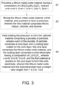
- FIGS. 4A and 4B are SEM images of a cathode material according to a first demonstrative example of the present disclosure.
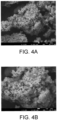
- FIGS. 5A and 5B are SEM images of a cathode material according to a second demonstrative example of the present disclosure.
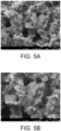
- FIGS. 6A and 6B are SEM images of a cathode material according to a third demonstrative example of the present disclosure.
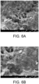
- FIGS. 7A and 7B are SEM images of a cathode material according to a comparative example of the present disclosure.
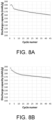
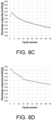
- FIGS. 8A to 8D are plots of discharge capacity vs. cycle number for button cells made using the first demonstrative example, the second demonstrative example, the third demonstrative example and the comparative example of the present disclosure.
- Table 1 below shows the discharge capacity at the first cycle and the forty-fifth cycle for the button cells made using the first demonstrative example, the second demonstrative example, the third demonstrative example and the comparative example.
- the cathode of each button cells is made using the first demonstrative example, the second demonstrative example, the third demonstrative example and the comparative example, respectively.
- the anode of each button cells is made using lithium.
- the button cells undergo testing under specific conditions, including a voltage window ranging from 2.5 V to 4.4 V, a C-rate of 0.1 C, and a temperature of 55 °C.
- the button cells are charged by a constant current (CC) method and discharged by a constant current constant voltage (CCCV) method.
- CC constant current
- CCCV constant current constant voltage
- the button cells are discharged at a constant current until they reach a specified voltage limit. Once the voltage limit is reached, the button cells are then discharged at a constant voltage until they are fully discharged.
- the discharge capacity of the second demonstrative example is 196.18 mAh/g, slightly higher than the discharge capacity of the comparative example.
- chlorine and fluorine has an amount ratio of 4.77:1.23.
- the discharge capacity of the first demonstrative example is 189.49 mAh/g, slightly lower than the discharge capacity of the comparative example. However, the differences are not significant.
- chlorine and fluorine has an amount ratio of 5.19:0.81.
- the discharge capacity of the first demonstrative example is 160.21 mAh/g, showing an improvement of 8.31% compared to the discharge capacity of the comparative example, which is 147.91 mAh/g.
- the discharge capacity of the second demonstrative example is 166.90 mAh/g, showing an improvement of 12.83% compared to the discharge capacity of the comparative example, which is 147.91 mAh/g. Based on the results, it can be inferred that the incorporation of chlorine and fluorine in the solid electrolyte results in the cathode material with high discharge capacity.
- the solid electrolyte formulated with a chlorine-to-fluorine amount ratio ranged from 5.3:0.7 to 4.5:1.5 demonstrates superior performance.
- Table 1 1st Cycle Discharge Capacity (mAh/g) 45th Cycle Discharge Capacity (mAh/g) First Demonstrative Example 189.49 160.21 Second Demonstrative Example 196.18 166.90 Third Demonstrative Example 157.60 123.62 Comparative Example 192.97 147.91
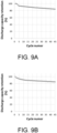
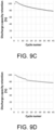
- FIGS. 9A to 9D are plots of discharge capacity retention vs. cycle number for button cells made using the first demonstrative example, the second demonstrative example, the third demonstrative example and the comparative example of the present disclosure.
- Table 2 shows the discharge capacity retention at the forty-fifth cycle for the button cells made using the first demonstrative example, the second demonstrative example, the third demonstrative example and the comparative example.
- the discharge capacity retention of the first demonstrative example is 84.55 %, showing an improvement of 10.31 % compared to the discharge capacity of the comparative example, which is 76.65 %.
- the discharge capacity of the second demonstrative example is 85.07 %, showing an improvement of 10.98 % compared to the discharge capacity of the comparative example, which is 76.65 %.
- the discharge capacity of the second demonstrative example is 166.90 mAh/g, showing an improvement of 2.34 % compared to the discharge capacity of the comparative example, which is 76.65 %.
- the incorporation of chlorine and fluorine in the solid electrolyte results in the cathode material with high discharge capacity retention.
- the solid electrolyte formulated with a chlorine-to-fluorine amount ratio ranged from 5.3:0.7 to 4.5:1.5 demonstrates superior performance.
- Table 2 45th Cycle Discharge Capacity Retention First Demonstrative Example 84.55 % Second Demonstrative Example 85.07 % Third Demonstrative Example 78.44 % Comparative Example 76.65%
- the present disclosure provides a cathode material and a preparation method thereof for obtaining a solid electrolyte coating through an organic solvent, thereby eliminating the adverse effects of moisture on the cathode material and enhancing the electrochemical performance.
- the cathode material includes a plurality of particles. Each of the plurality of particles includes a core layer and a coating layer coated thereon.
- the core layer includes a lithium metal oxide material having a composition of Li[Ni a Co b Mn c Al d ]O 2 .
- the coefficient "a" satisfies the conditions of 0.8 ⁇ a ⁇ 1.
- the coating layer of the cathode material includes a solid electrolyte having a composition of Li 3 InCl x F y .
- the incorporation of chlorine and fluorine in the solid electrolyte further results in the cathode material with high discharge capacity and high discharge capacity retention.
- the coefficients "x" and "y” satisfy the conditions of 4 ⁇ x ⁇ 5.5 and 0.5 ⁇ y ⁇ 2.
- the lithium metal oxide material in the core layer and the solid electrolyte in the coating layer have a weight ratio ranged from 1:0.3 to 1:0.6, resulting in the cathode material with a uniform core-shell structure.
- the lithium metal oxide material, a first material and an organic solvent are mixed and heat-treated to form the cathode material.
- wet mixing using the organic solvent offers cost efficiency and easy controllability. It not only enhances the solid dispersion of the cathode material but also eliminates the adverse effects of moisture.
- the first material is reacted and undergoes an in-situ synthesis on the surface of the cathode material particles, resulting in the formation of a solid electrolyte. This leads to the formation of the cathode material with a uniform core-shell structure, thereby enhancing the electrochemical performance.
- the heat treatment has a temperature ranged from 100 °C to 250 °C, ensuring that the preparation method of the cathode material is energy-efficient, cost-effective and environmentally friendly.
Landscapes
- Chemical & Material Sciences (AREA)
- Electrochemistry (AREA)
- General Chemical & Material Sciences (AREA)
- Chemical Kinetics & Catalysis (AREA)
- Inorganic Chemistry (AREA)
- Engineering & Computer Science (AREA)
- Organic Chemistry (AREA)
- Composite Materials (AREA)
- Manufacturing & Machinery (AREA)
- Physics & Mathematics (AREA)
- Condensed Matter Physics & Semiconductors (AREA)
- General Physics & Mathematics (AREA)
- Materials Engineering (AREA)
- Battery Electrode And Active Subsutance (AREA)
- Secondary Cells (AREA)
- Inorganic Compounds Of Heavy Metals (AREA)
- Primary Cells (AREA)
Description
- The present disclosure relates to a cathode material and a preparation method thereof, and more particularly to a cathode material and a preparation method thereof for obtaining a solid electrolyte coating layer through an organic solvent thereby enhancing the electrochemical performance.
- In recent years, the development of solid-state batteries has become a mainstream trend due to increasing emphasis on safety and energy density. While solid-state batteries show promise for improving upon traditional lithium batteries, there is still room for further enhancements. In terms of cathode materials, high-nickel cathode materials are known to be sensitive to moisture. As for solid electrolytes, it is a challenging task to reduce their thickness while improving their mechanical properties.
-
US 2022/216507 A1 discloses a solid electrolyte material for a lithium secondary battery, an electrode, and a battery, relating in particular to an additive material capable of improving rapid transmission of ions in lithium secondary battery electrodes, a preparation method therefor and application thereof, and a solid electrolyte material for a secondary battery, a preparation method therefor and application thereof, as well as an electrode, an electrolyte thin layer, and a preparation method therefor. - Wang Jing et al.: High Lithium-Ion Conductivity, Halide-Coated, Ni-Rich NCM Improves Cycling Stability in Sulfide All-Solid-State Batteries", ACS APPLIED ENERGIE MATERIALS, vol. 6, no. 7, pages 3671-3681 discloses a halide electrolyte coating with high lithium-ion conductivity obtained by mechanical coating under n-heptane solvent and annealing at 200 °C of Ni-rich LiNi0.83Co0.14Mn0.03O2 (NCM) for Li6PS5Cl-type all-solid-state batteries. A 10% Li3InCl6-coated NCM material was assembled into a 10% LIC@NCM/Li6PS5Cl/In all-solid-state battery with an initial charge capacity of 201.3 mAh g-1, a discharge specific capacity of 158.7 mAh g-1, and a Coulombic efficiency of 79.06%. After 100 cycles at room temperature at 0.1C current density, the capacity retention was 92% and the capacity retention was 72% after 270 cycles. In comparison, all-solid-state batteries using matched Li6PS5Cl and untreated NCM had a capacity retention rate of 53% after 100 cycles at 0.1C under the same charge/discharge regime and environment. It is indicated that the cycling performance and rate performance of the NCM material significantly improve after the 10% LIC coating. In this paper, X-ray diffraction (XRD), X-ray absorption spectroscopy (XAS), X-ray photoelectron spectroscopy (XPS), high-resolution high-resolution transmission electron microscopy (HR-TEM), scanning electron microscopy (SEM), and other tests and analyses confirmed the following: the pregenerated interfacial layer of approximately 2 nm on the surface of NCM after the 10% halide solid electrolyte coating improves the structural stability of the material during charging and discharging, the LIC coating layer slows down the decomposition of LI6PS5Cl during cycling, and the capacity increase at high rates is due to the reduction of the interfacial impedance between the cathode material and LI6PS5Cl solid electrolyte.
- Among different types of solid-state electrolytes, oxide solid electrolytes, sulfide solid electrolytes, and halide solid electrolytes have emerged as the most promising options for mass production. Particularly, the halide solid electrolytes have received significant attention in recent years due to their remarkable properties such as high stability, safety, ion conductivity, and low interfacial impedance. However, similar to high-nickel cathode materials, halide solid electrolytes are also sensitive to moisture. Moreover, the electrochemical performance of the widely used Li3InCl6 in halide solid electrolytes has room for improvement.
- Therefore, there is a need to provide a cathode material and a preparation method thereof for obtaining a solid electrolyte coating layer through an organic solvent, thereby eliminating the adverse effects of moisture on the cathode material and enhancing the electrochemical performance.
- An object of the present disclosure is to provide a cathode material having a solid electrolyte coating layer obtained through an organic solvent, thereby eliminating the adverse effects of moisture on the cathode material and enhancing the electrochemical performance. The cathode material includes a plurality of particles. Each of the plurality of particles includes a core layer and a coating layer coated thereon. The core layer includes a lithium metal oxide material having a composition of Li[NiaCobMncAld]O2. The coefficient "a" satisfies the conditions of 0.8<a<1. By incorporating the core layer with high nickel content, the low-cost cathode material with high energy density is achieved. The coating layer of the cathode material includes a solid electrolyte having a composition of Li3InClxFy. The incorporation of chlorine and fluorine in the solid electrolyte further results in the cathode material with high discharge capacity and high discharge capacity retention. The coefficients "x" and "y" satisfy the conditions of 4≤x≤5.5 and 0.5≤y≤2. By controlling the amount ratio of chlorine and fluorine in the solid electrolyte, the electrochemical performance of the cathode material is enhanced. The lithium metal oxide material in the core layer and the solid electrolyte in the coating layer have a weight ratio ranged from 1:0.3 to 1:0.6, resulting in the cathode material with a uniform core-shell structure.
- Another object of the present disclosure is to provide a preparation method of a cathode material for obtaining a solid electrolyte coating layer through an organic solvent, thereby eliminating the adverse effects of moisture on the cathode material and enhancing the electrochemical performance. A lithium metal oxide material, a first material and an organic solvent are mixed and heat-treated to form the cathode material. Compared to dry mixing, wet mixing using the organic solvent offers cost efficiency and easy controllability. It not only enhances the solid dispersion of the cathode material but also eliminates the adverse effects of moisture. Furthermore, through wet mixing, the first material is reacted and undergoes an in-situ synthesis on the surface of the cathode material particles, resulting in the formation of a solid electrolyte. This leads to the formation of the cathode material with a uniform core-shell structure, thereby enhancing the electrochemical performance. The heat treatment has a temperature ranged from 100 °C to 250 °C, ensuring that the preparation method of the cathode material is energy-efficient, cost-effective and environmentally friendly.
- To achieve the abovementioned object, a cathode material including a plurality of particles according to appended
claim 1 is provided. Each of the plurality of particles includes a core layer and a coating layer. The core layer includes a lithium metal oxide material. The lithium metal oxide material has a composition of Li[NiaCobMncAld]O2. The coefficients "a", "b", "c", and "d" satisfy the conditions of a+b+c+d=1, 0.8<a<1, 0<b<1, 0≤c<1, and 0≤d<1. The coating layer is coated on the core layer and includes a solid electrolyte. A first material is reacted on the core layer to in-situ synthesize the solid electrolyte. The solid electrolyte has a composition of Li3InClxFy. The coefficients "x" and "y" satisfy the conditions of x+y=6, 4≤x≤5.5, and 0.5≤y≤2. The lithium metal oxide material, the first material, and a solvent are mixed to form a precursor. The precursor is heat-treated to form the cathode material. The first material includes lithium, indium, chlorine, and fluorine. The lithium metal oxide material and the solid electrolyte have a weight ratio ranged from 1:0.3 to 1:0.6. - In an embodiment, the coefficient "a" satisfies the condition of 0.9<a<1.
- In an embodiment, the lithium metal oxide material and the solid electrolyte have a weight ratio ranged from 1:0.4 to 1:0.5.
- In an embodiment, each of the plurality of particles has a particle size, and the coating layer has a thickness. The particle size and the thickness have a ratio ranged from 6:1 to 40:1.
- In an embodiment, the particle size is ranged from 5 µm to 20 µm, and the thickness is ranged from 0.5 µm to 3 µm.
- In an embodiment, the first material comprises lithium chloride (LiCl), lithium fluoride (LiF) and indium chloride (InCl3).
- In an embodiment, the solvent includes a volatile organic solvent.
- In an embodiment, the precursor is heat-treated in a vacuum environment or an inert atmosphere to form the cathode material.
- In an embodiment, the precursor is heat-treated at a temperature to form the cathode material. The temperature is ranged from 100 °C to 250 °C.
- To further achieve the abovementioned object, a preparation method of a cathode material according to appended claim 8 is provided. The preparation method includes steps of: (a) providing a lithium metal oxide material having a composition of Li[NiaCobMncAld]O2, wherein a+b+c+d=1, 0.8<a<1, 0<b<1, 0≤c<1, and 0≤d<1; (b) mixing the lithium metal oxide material with a first material and a solvent to form a precursor, wherein the first material includes lithium, indium, chlorine, and fluorine; and (c) heat-treating the precursor to form the cathode material comprising a plurality of particles, wherein each of the plurality of particles includes a core layer and a coating layer coated on the core layer, the core layer includes the lithium metal oxide material, and the coating layer includes a solid electrolyte having a composition of Li3InClxFy, wherein x+y=6, 4≤x≤5.5, and 0.5≤y≤2, and the first material is reacted on the core layer to form the solid electrolyte, wherein the lithium metal oxide material and the solid electrolyte have a weight ratio ranged from 1:0.3 to 1:0.6.
- In an embodiment, the coefficient "a" satisfies the condition of 0.9<a<1.
- In an embodiment, the lithium metal oxide material and the solid electrolyte have a weight ratio ranged from 1:0.4 to 1:0.5.
- In an embodiment, each of the plurality of particles has a particle size, and the coating layer has a thickness. The particle size and the thickness have a ratio ranged from 6:1 to 40:1.
- In an embodiment, the particle size is ranged from 5 µm to 20 µm, and the thickness is ranged from 0.5 µm to 3 µm.
- In an embodiment, the first material comprises lithium chloride (LiCl), lithium fluoride (LiF), and indium chloride (InCl3).
- In an embodiment, the solvent includes a volatile organic solvent.
- In an embodiment, the precursor is heat-treated in a vacuum environment or an inert atmosphere to form the cathode material.
- In an embodiment, the precursor is heat-treated at a temperature to form the cathode material. The temperature is ranged from 100 °C to 250 °C.
-
-
FIG. 1 is a schematic diagram of a cathode material particle according to an embodiment of the present disclosure; -
FIG. 2 is a cross-sectional SEM image of cathode material particles according to an embodiment of the present disclosure; -
FIG. 3 is a flow chart of a preparation method of a cathode material according to an embodiment of the present disclosure; -
FIGS. 4A and 4B are SEM images of a cathode material according to a first demonstrative example of the present disclosure; -
FIGS. 5A and 5B are SEM images of a cathode material according to a second demonstrative example of the present disclosure; -
FIGS. 6A and 6B are SEM images of a cathode material according to a third demonstrative example of the present disclosure; -
FIGS. 7A and 7B are SEM images of a cathode material according to a comparative example of the present disclosure; -
FIG. 8A is a plot of discharge capacity vs. cycle number according to the first demonstrative example of the present disclosure; -
FIG. 8B is a plot of discharge capacity vs. cycle number according to the second demonstrative example of the present disclosure; -
FIG. 8C is a plot of discharge capacity vs. cycle number according to the third demonstrative example of the present disclosure; -
FIG. 8D is a plot of discharge capacity vs. cycle number according to the comparative example of the present disclosure; -
FIG. 9A is a plot of discharge capacity retention vs. cycle number according to the first demonstrative example of the present disclosure; -
FIG. 9B is a plot of discharge capacity retention vs. cycle number according to the second demonstrative example of the present disclosure; -
FIG. 9C is a plot of discharge capacity retention vs. cycle number according to the third demonstrative example of the present disclosure; and -
FIG. 9D is a plot of discharge capacity retention vs. cycle number according to the comparative example of the present disclosure. - The present disclosure will now be described more specifically with reference to the following embodiments. It is to be noted that the following descriptions of preferred embodiments of this disclosure are presented herein for purpose of illustration and description only. It is not intended to be exhaustive or to be limited to the precise form disclosed. In addition, although the "first," "second," "third," and the like terms in the claims be used to describe the various elements can be appreciated, these elements should not be limited by these terms, and these elements are described in the respective embodiments are used to express the different reference numerals, these terms are only used to distinguish one element from another element. For example, a first element could be termed a second element, and, similarly, a second element could be termed a first element, without departing from the scope of example embodiments. Besides, "and/or" and the like may be used herein for including any or all combinations of one or more of the associated listed items. Alternatively, the word "about" means within an acceptable standard error of ordinary skill in the art-recognized average. In addition to the operation / working examples, or unless otherwise specifically stated otherwise, in all cases, all of the numerical ranges, amounts, values and percentages, such as the number for the herein disclosed materials, time duration, temperature, operating conditions, the ratio of the amount, and the like, should be understood as the word "about" decorator. Accordingly, unless otherwise indicated, the numerical parameters of the present invention and scope of the appended patent proposed is to follow changes in the desired approximations. At least, the number of significant digits for each numerical parameter should at least be reported and explained by conventional rounding technique is applied. Herein, it can be expressed as a range between from one endpoint to the other or both endpoints. Unless otherwise specified, all ranges disclosed herein are inclusive.
-
FIG. 1 is a schematic diagram of a cathode material particle according to an embodiment of the present disclosure.FIG. 2 is a cross-sectional SEM image of cathode material particles according to an embodiment of the present disclosure.FIG. 2 is obtained by a Focused ion beam scanning electron microscopy (FIB-SEM). In the embodiment, the cathode material includes a plurality ofparticles 1. Each of the plurality ofparticles 1 includes acore layer 10 and acoating layer 20. Thecore layer 10 includes a lithium metal oxide material. The lithium metal oxide material has a composition of Li[NiaCobMncAld]O2. The coefficients "a", "b", "c", and "d" satisfy the conditions of a+b+c+d=1, 0.8<a<1, 0<b<1, 0≤c<1, and 0≤d<1. Thecoating layer 20 is coated on thecore layer 10 and includes a solid electrolyte. A first material is reacted on thecore layer 10 to in-situ synthesize the solid electrolyte. The solid electrolyte has a composition of Li3InClxFy. The coefficients "x" and "y" satisfy the conditions of x+y=6, 4≤x≤5.5 and 0.5≤y≤2. The lithium metal oxide material, the first material, and a solvent are mixed to form a precursor. The precursor is heat-treated to form the cathode material. The first material includes lithium, indium, chlorine, and fluorine. The lithium metal oxide material and the solid electrolyte have a weight ratio ranged from 1:0.3 to 1:0.6. The incorporation of chlorine and fluorine in the solid electrolyte results in the cathode material with high discharge capacity and high discharge capacity retention. In the embodiment, preferably but not exclusively, the lithium metal oxide material includes a lithium nickel cobalt manganese oxide (NCM) material having a composition of Li[NiaCobMnc]O2. The coefficients "a", "b", and "c" satisfy the conditions of a=0.83, b=0.12, and c=0.05. These values indicate that nickel, cobalt and manganese in the NCM material have an amount ratio of 83: 12:5. Preferably but not exclusively, the lithium nickel cobalt manganese oxide material is prepared by a solid-state synthesis method. In other embodiments, the lithium metal oxide material includes a lithium nickel cobalt manganese oxide (NCM) material with a different amount ratio, a lithium nickel cobalt aluminum oxide (NCA) material having a composition of Li[NiaCobAld]O2, or a lithium nickel cobalt manganese aluminum oxide (NCMA) material having a composition of Li[NiaCobMncAld]O2, and is prepared by a sol-gel process. In an embodiment, preferably but not exclusively, the lithium metal oxide material has a composition of Li[NiaCobMncAld]O2, and the coefficients "a" satisfies the condition of 0.9<a<1. This condition indicates that the proportion of nickel in the metallic elements other than lithium in the lithium metal oxide material is more than 90%. Preferably but not exclusively, the lithium metal oxide material includes a lithium nickel cobalt manganese aluminum oxide (NCMA) material having a composition of Li[NiaCobMncAld]O2. The coefficients "a", "b", "c", and "d" satisfy the conditions of a=0.93, b=0.03, c=0.03, and d=0.01. These values indicate that nickel, cobalt, manganese and aluminum in the NCMA material have an amount ratio of 93:3:3:1. By incorporating thecore layer 10 with high nickel content, the low-cost cathode material with high energy density is achieved. It should be noted that the types, the composition, and the preparation processes of the lithium metal oxide material are adjustable according to the practical requirements. The present disclosure is not limited thereto, and not redundantly described herein. - Preferably but not exclusively, in the composition of Li3InClxFy, the coefficients "x" and "y" further satisfy the conditions of 4≤x≤5.5 and 0.5≤y≤2. These conditions indicate that chlorine and fluorine have an amount ratio ranged from 5.5:0.5 to 4:2. By controlling the amount ratio of chlorine and fluorine in the solid electrolyte, the electrochemical performance of the cathode material is enhanced. Even more preferably, the amount ratio of chlorine to fluorine is ranged from 5.3:0.7 to 4.5:1.5. The present disclosure is not limited thereto.
- In an embodiment, preferably but not exclusively, the lithium metal oxide material and the solid electrolyte have a weight ratio ranged from 1:0.4 to 1:0.5, resulting in the cathode material with a uniform core-shell structure. As shown in
FIG. 2 , each of the plurality of theparticles 1 includes a particle size T1, and thecoating layer 20 has a thickness T2. The particle size T1 and the thickness T2 have a ratio ranged from 6:1 to 40:1. The particle size T1 is ranged from 5 µm to 20 µm, and the thickness T2 is ranged from 0.5 µm to 3 µm. - In the embodiment, the first material comprises lithium chloride (LiCl), lithium fluoride (LiF) and indium chloride (InCl3). The solvent is a volatile organic solvent. Compared to dry mixing, wet mixing using the organic solvent offers cost efficiency and easy controllability. It not only enhances the solid dispersion of the cathode material but also eliminates the adverse effects of moisture. Furthermore, through wet mixing, the first material is reacted and undergoes an in-situ synthesis on the surface of the cathode material particles, resulting in the formation of a solid electrolyte. This leads to the formation of the cathode material with a uniform core-shell structure, thereby enhancing the electrochemical performance. In the first material, lithium, indium, and halogen elements (the sum of chlorine and fluorine) have an amount ratio of 3:1:6. Preferably but not exclusively, the volatile organic solvent is an ethanol. However, it should be noted that other volatile organic solvents that do not react with the lithium metal oxide material and the first material are also suitable, and their description is not redundantly described herein. In the embodiment, the lithium metal oxide material, the first material, a conductive additive, a binder, and the solvent are mixed and reacted to form the precursor. The lithium metal oxide material, the first material, the conductive additive, the binder, and the solvent are reacted in a vacuum environment or an inert atmosphere to form the cathode material. Preferably but not exclusively, the conductive additive includes a nano carbon tube, a conductive graphite, a conductive carbon black, an acetylene black, or a vapor grown carbon fiber (VGCF). The binder includes a polyvinylidene difluoride (PVDF) or a polytetrafluoroethene (PTFE). The vacuum environment is in a reaction flask having a pressure less than or equal to 10-3 torr. The inert atmosphere is an argon atmosphere or a nitrogen atmosphere. The present disclosure is not limited thereto.
- According to the aforementioned cathode material, a preparation for the cathode material is provided.
FIG. 3 is a flow chart of a preparation method of a cathode material according to an embodiment of the present disclosure. First, as show in the step S1, a lithium metal oxide material is provided. The lithium metal oxide material has a composition of Li[NiaCobMncAld]O2. The coefficients "a", "b", "c", and "d" satisfy the conditions of a+b+c+d=1, 0.8<a<1, 0<b<1, 0≤c<1, and 0≤d<1. In the embodiment, preferably but not exclusively, the lithium metal oxide material includes a lithium nickel cobalt manganese oxide (NCM) material having a composition of Li[NiaCobMnc]O2. The coefficients "a", "b", and "c" satisfy the conditions of a=0.83, b=0.12, and c=0.05. These values indicate that nickel, cobalt and manganese in the NCM material have an amount ratio of 83: 12:5. Preferably but not exclusively, the lithium nickel cobalt manganese oxide material is prepared by a solid-state synthesis method. In other embodiments, the lithium metal oxide material includes a lithium nickel cobalt manganese oxide (NCM) material with a different composition ratio, a lithium nickel cobalt aluminum oxide (NCA) material having a composition of Li[NiaCobAld]O2, or a lithium nickel cobalt manganese aluminum oxide (NCMA) material having a composition of Li[NiaCobMncAld]O2, and is prepared by a sol-gel process. In an embodiment, preferably but not exclusively, the lithium metal oxide material has a composition of Li[NiaCobMncAld]O2, and the coefficients "a" satisfies the condition of 0.9<a<1. This condition indicates that the proportion of nickel in the metallic elements other than lithium in the lithium metal oxide material is more than 90%. Preferably but not exclusively, the lithium metal oxide material includes a lithium nickel cobalt manganese aluminum oxide (NCMA) material having a composition of Li[NiaCobMncAld]O2. The coefficients "a", "b", "c", and "d" satisfy the conditions of a=0.93, b=0.03, c=0.03, and d=0.01. These values indicate that nickel, cobalt, manganese and aluminum in the NCMA material have an amount ratio of 93:3:3:1. By incorporating thecore layer 10 with high nickel content, the low-cost cathode material with high energy density is achieved. It should be noted that the types, the composition ratios, and the preparation processes of the lithium metal oxide material are adjustable according to the practical requirements. The present disclosure is not limited thereto, and not redundantly described herein. - After that, as shown in the step S2, the lithium metal oxide material, the first material, and a solvent are mixed to form a precursor. The first material includes lithium, indium, chlorine, and fluorine. The first material comprises lithium chloride (LiCl), lithium fluoride (LiF) and indium chloride (InCl3). The solvent is a volatile organic solvent. Compared to dry mixing, wet mixing using the organic solvent offers cost efficiency and easy controllability. It not only enhances the solid dispersion of the cathode material but also eliminates the adverse effects of moisture. Furthermore, through wet mixing, the first material is reacted and undergoes an in-situ synthesis on the surface of the cathode material particles, resulting in the formation of a solid electrolyte. This leads to the formation of the cathode material with a uniform core-shell structure, thereby enhancing the electrochemical performance. In the first material, lithium, indium, and halogen elements (the sum of chlorine and fluorine) have an amount ratio of 3:1:6. Preferably but not exclusively, the volatile organic solvent is an ethanol. However, it should be noted that other volatile organic solvents that do not react with the lithium metal oxide material and the first material are also suitable, and their description is not redundantly described herein. In the embodiment, the lithium metal oxide material, the first material, a conductive additive, a binder, and the solvent are mixed and reacted to form the precursor. The lithium metal oxide material, the first material, the conductive additive, the binder, and the solvent are reacted in a vacuum environment or an inert atmosphere to form the precursor. Preferably but not exclusively, the conductive additive includes a nano carbon tube, a conductive graphite, a conductive carbon black, an acetylene black, or a vapor grown carbon fiber (VGCF). The binder includes a polyvinylidene difluoride (PVDF) or a polytetrafluoroethene (PTFE). The vacuum environment is in a reaction flask having a pressure less than or equal to 10-3 torr. The inert atmosphere is an argon atmosphere or a nitrogen atmosphere. The present disclosure is not limited thereto.
- Finally, as shown in the step S3, the precursor is heat-treated to form the cathode material including a plurality of
particles 1. Each of the plurality ofparticles 1 includes acore layer 10 and acoating layer 20. Thecore layer 10 includes the lithium metal oxide material. The coating layer is coated on the core layer and includes a solid electrolyte. The first material is reacted on thecore layer 20 to in-situ synthesize the solid electrolyte. The solid electrolyte has a composition of Li3InClxFy. The coefficients "x" and "y" satisfy the conditions of x+y=6, 4≤x≤5.5, and 0.5≤y≤2. . The lithium metal oxide material and the solid electrolyte have a weight ratio ranged from 1:0.3 to 1:0.6. Preferably but not exclusively, the precursor is heat-treated in a vacuum environment or an inert atmosphere to form the cathode material. The vacuum environment is in a reaction flask having a pressure less than or equal to 10-3 torr. The inert atmosphere is an argon atmosphere or a nitrogen atmosphere. The present disclosure is not limited thereto. The precursor is heat-treated at a temperature ranged from 100 °C to 250 °C. Preferably but not exclusively, the temperature is ranged from 160 °C to 200 °C, ensuring that the preparation method of the cathode material is energy-efficient, cost-effective and environmentally friendly. In the embodiment, the precursor is uniformly coated on a metal foil and hot treated, and then cut to form the cathode sheet. - Preferably but not exclusively, in the composition of Li3InClxFy, the coefficients "x" and "y" further satisfy the conditions of 4≤x≤5.5 and 0.5≤y≤2. These conditions indicate that chlorine and fluorine have an amount ratio ranged from 5.5:0.5 to 4:2. By controlling the amount ratio of chlorine and fluorine in the solid electrolyte, the electrochemical performance of the cathode material is enhanced. Even more preferably, the amount ratio of chlorine to fluorine is ranged from 5.3:0.7 to 4.5:1.5. The present disclosure is not limited thereto. In an embodiment, preferably but not exclusively, the lithium metal oxide material and the solid electrolyte have a weight ratio ranged from 1:0.4 to 1:0.5, resulting in the cathode material with a uniform core-shell structure. Each of the plurality of the
particles 1 includes a particle size T1, and thecoating layer 20 has a thickness T2. The particle size T1 and the thickness T2 have a ratio ranged from 6:1 to 40:1. The particle size T1 is ranged from 5 µm to 20 µm, and the thickness T2 is ranged from 0.5 µm to 3 µm. - The preparation process and the effects of the present disclosure are further described in detail below through a comparative example and demonstrative examples.
- The first demonstrative example is a cathode material prepared through the following steps. First, a lithium metal oxide material is provided. The lithium metal oxide material has a composition of Li[NiaCobMnc]O2. The coefficients "a", "b", and "c" satisfy the conditions of a=0.82, b=0.13, and c=0.05. This indicates that the lithium metal oxide material is a lithium nickel cobalt manganese oxide material, where nickel, cobalt and manganese have an amount ratio of 83:12:5.
- After that, 0.68 grams of lithium metal oxide material, 0.3 grams of first material, 0.02 grams of vapor grown carbon fiber (VGCF), 0.01 grams of polytetrafluoroethene (PTFE), and 3 milliliters of ethanol are mixed and ground at a temperature of 120 °C to form a precursor. The first material of the first demonstrative example includes 0.083 grams of lithium chloride (LiCl), 0.0189 grams of lithium fluoride (LiF), and 0.199 grams of indium chloride (InCl3). This indicates that in the first material, lithium, indium, chloride, and fluoride have an amount ratio of 3:1:5.19:0.81.
- Finally, the precursor is heat-treated to form the cathode material. The precursor is heat-treated in an argon atmosphere at a temperature of 180 °C for a duration of 2 hours.
- The preparation method of the second demonstrative example is roughly similar to that of the first demonstrative example. The first material of the second demonstrative example includes 0.068 grams of lithium chloride (LiCl), 0.029 grams of lithium fluoride (LiF), and 0.203 grams of indium chloride (InCl3). This indicates that in the first material, lithium, indium, chloride, and fluoride have an amount ratio of 3:1:4.77:1.23.
- The preparation method of the third demonstrative example is roughly similar to that of the first demonstrative example. The first material of the third demonstrative example includes 0.053 grams of lithium chloride (LiCl), 0.04 grams of lithium fluoride (LiF), and 0.207 grams of indium chloride (InCl3). This indicates that in the first material, lithium, indium, chloride, and fluoride have an amount ratio of 3:1:4.35:1.65.
- The preparation method of the comparative example is roughly similar to that of the first demonstrative example. The first material of the comparative example includes 0.11 grams of lithium chloride (LiCl) and 0.19 grams of indium chloride (InCl3). This indicates that the first material does not include fluoride, and lithium, indium, and chloride have an amount ratio of 3:1:4.35:1.65.
-
FIGS. 4A and 4B are SEM images of a cathode material according to a first demonstrative example of the present disclosure.FIGS. 5A and 5B are SEM images of a cathode material according to a second demonstrative example of the present disclosure.FIGS. 6A and 6B are SEM images of a cathode material according to a third demonstrative example of the present disclosure.FIGS. 7A and 7B are SEM images of a cathode material according to a comparative example of the present disclosure.FIGS. 8A to 8D are plots of discharge capacity vs. cycle number for button cells made using the first demonstrative example, the second demonstrative example, the third demonstrative example and the comparative example of the present disclosure. Table 1 below shows the discharge capacity at the first cycle and the forty-fifth cycle for the button cells made using the first demonstrative example, the second demonstrative example, the third demonstrative example and the comparative example. The cathode of each button cells is made using the first demonstrative example, the second demonstrative example, the third demonstrative example and the comparative example, respectively. The anode of each button cells is made using lithium. The button cells undergo testing under specific conditions, including a voltage window ranging from 2.5 V to 4.4 V, a C-rate of 0.1 C, and a temperature of 55 °C. The button cells are charged by a constant current (CC) method and discharged by a constant current constant voltage (CCCV) method. During the constant current constant voltage (CCCV) discharging, the button cells are discharged at a constant current until they reach a specified voltage limit. Once the voltage limit is reached, the button cells are then discharged at a constant voltage until they are fully discharged. As shown inFIGS. 8A to 8D and Table 1, during the first cycle, the discharge capacity of the second demonstrative example is 196.18 mAh/g, slightly higher than the discharge capacity of the comparative example. In the second demonstrative example, chlorine and fluorine has an amount ratio of 4.77:1.23. On the other hand, the discharge capacity of the first demonstrative example is 189.49 mAh/g, slightly lower than the discharge capacity of the comparative example. However, the differences are not significant. In the first demonstrative example, chlorine and fluorine has an amount ratio of 5.19:0.81. During the forty-fifth cycle, the discharge capacity of the first demonstrative example is 160.21 mAh/g, showing an improvement of 8.31% compared to the discharge capacity of the comparative example, which is 147.91 mAh/g. The discharge capacity of the second demonstrative example is 166.90 mAh/g, showing an improvement of 12.83% compared to the discharge capacity of the comparative example, which is 147.91 mAh/g. Based on the results, it can be inferred that the incorporation of chlorine and fluorine in the solid electrolyte results in the cathode material with high discharge capacity. Preferably, the solid electrolyte formulated with a chlorine-to-fluorine amount ratio ranged from 5.3:0.7 to 4.5:1.5 demonstrates superior performance.Table 1 1st Cycle Discharge Capacity (mAh/g) 45th Cycle Discharge Capacity (mAh/g) First Demonstrative Example 189.49 160.21 Second Demonstrative Example 196.18 166.90 Third Demonstrative Example 157.60 123.62 Comparative Example 192.97 147.91 -
FIGS. 9A to 9D are plots of discharge capacity retention vs. cycle number for button cells made using the first demonstrative example, the second demonstrative example, the third demonstrative example and the comparative example of the present disclosure. Table 2 below shows the discharge capacity retention at the forty-fifth cycle for the button cells made using the first demonstrative example, the second demonstrative example, the third demonstrative example and the comparative example. As shown inFIGS. 9A to 9D and Table 2, during the forty-fifth cycle, the discharge capacity retention of the first demonstrative example is 84.55 %, showing an improvement of 10.31 % compared to the discharge capacity of the comparative example, which is 76.65 %. The discharge capacity of the second demonstrative example is 85.07 %, showing an improvement of 10.98 % compared to the discharge capacity of the comparative example, which is 76.65 %. The discharge capacity of the second demonstrative example is 166.90 mAh/g, showing an improvement of 2.34 % compared to the discharge capacity of the comparative example, which is 76.65 %. Based on the results, it can be inferred that the incorporation of chlorine and fluorine in the solid electrolyte results in the cathode material with high discharge capacity retention. Preferably, the solid electrolyte formulated with a chlorine-to-fluorine amount ratio ranged from 5.3:0.7 to 4.5:1.5 demonstrates superior performance.Table 2 45th Cycle Discharge Capacity Retention First Demonstrative Example 84.55 % Second Demonstrative Example 85.07 % Third Demonstrative Example 78.44 % Comparative Example 76.65% - In summary, the present disclosure provides a cathode material and a preparation method thereof for obtaining a solid electrolyte coating through an organic solvent, thereby eliminating the adverse effects of moisture on the cathode material and enhancing the electrochemical performance. The cathode material includes a plurality of particles. Each of the plurality of particles includes a core layer and a coating layer coated thereon. The core layer includes a lithium metal oxide material having a composition of Li[NiaCobMncAld]O2. The coefficient "a" satisfies the conditions of 0.8<a<1. By incorporating the core layer with high nickel content, the low-cost cathode material with high energy density is achieved. The coating layer of the cathode material includes a solid electrolyte having a composition of Li3InClxFy. The incorporation of chlorine and fluorine in the solid electrolyte further results in the cathode material with high discharge capacity and high discharge capacity retention. The coefficients "x" and "y" satisfy the conditions of 4≤x≤5.5 and 0.5≤y≤2. By controlling the amount ratio of chlorine and fluorine in the solid electrolyte, the electrochemical performance of the cathode material is enhanced. The lithium metal oxide material in the core layer and the solid electrolyte in the coating layer have a weight ratio ranged from 1:0.3 to 1:0.6, resulting in the cathode material with a uniform core-shell structure. The lithium metal oxide material, a first material and an organic solvent are mixed and heat-treated to form the cathode material. Compared to dry mixing, wet mixing using the organic solvent offers cost efficiency and easy controllability. It not only enhances the solid dispersion of the cathode material but also eliminates the adverse effects of moisture. Furthermore, through wet mixing, the first material is reacted and undergoes an in-situ synthesis on the surface of the cathode material particles, resulting in the formation of a solid electrolyte. This leads to the formation of the cathode material with a uniform core-shell structure, thereby enhancing the electrochemical performance. The heat treatment has a temperature ranged from 100 °C to 250 °C, ensuring that the preparation method of the cathode material is energy-efficient, cost-effective and environmentally friendly.
Claims (14)
- A cathode material comprising a plurality of particles (1), wherein each of the plurality of particles (1) is characterized by comprising:a core layer (10) comprising a lithium metal oxide material, wherein the lithium metal oxide material has a composition of Li[NiaCobMncAld]O2, wherein a+b+c+d=1, 0.8<a<1, 0<b<1, 0≤c<1, and 0≤d<1; anda coating layer (20) coated on the core layer (10) and comprising a solid electrolyte, wherein the solid electrolyte is formed by a reaction of a first material on the core layer (10) and has a composition of Li3InClxFy, x+y=6, 4≤x≤5.5, and 0.5≤y≤2, wherein the lithium metal oxide material, the first material, and a solvent are mixed to form a precursor, and the precursor is heat-treated to form the cathode material, wherein the first material comprises lithium, indium, chlorine, and fluorine, and the lithium metal oxide material and the solid electrolyte have a weight ratio ranged from 1:0.3 to 1:0.6.
- The cathode material according to claim 1, wherein 0.9<a<1.
- The cathode material according to claim 1, wherein the lithium metal oxide material and the solid electrolyte have a weight ratio ranged from 1:0.4 to 1:0.5.
- The cathode material according to claim 1, wherein each of the plurality of particles (1) has a particle size (T1), and the coating layer (20) has a thickness (T2), wherein the particle size (T1) and the thickness (T2) have a ratio ranged from 6:1 to 40:1, wherein the particle size (T1) is ranged from 5 µm to 20 µm, and the thickness (T2) is ranged from 0.5 µm to 3 µm.
- The cathode material according to claim 1, wherein the first material comprises lithium chloride (LiCl), lithium fluoride (LiF) and indium chloride (InCl3)
- The cathode material according to claim 1, wherein the solvent comprises a volatile organic solvent.
- The cathode material according to claim 1, wherein the precursor is heat-treated in a vacuum environment or an inert atmosphere to form the cathode material, wherein the precursor is heat-treated at a temperature to form the cathode material, and the temperature is ranged from 100 °C to 250 °C.
- A preparation method of a cathode material, characterized by comprising steps of:(a) providing a lithium metal oxide material having a composition of Li[NiaCobMncAld]O2, wherein a+b+c+d=1, 0.8<a<1, 0<b<1, 0≤c<1, and 0≤d<1;(b) mixing the lithium metal oxide material with a first material and a solvent to form a precursor, wherein the first material comprises lithium, indium, chlorine, and fluorine; and(c) heat-treating the precursor to form the cathode material comprising a plurality of particles (1), wherein each of the plurality of particles (1) comprises a core layer (10) and a coating layer (20) coated on the core layer (10), the core layer (10) comprises the lithium metal oxide material, and the coating layer (20) comprises a solid electrolyte having a composition of Li3InClxFy, wherein x+y=6, 4≤x≤5.5, and 0.5≤y≤2, and the first material is reacted on the core layer (10) to form the solid electrolyte, wherein the lithium metal oxide material and the solid electrolyte have a weight ratio ranged from 1:0.3 to 1:0.6.
- The preparation method of the cathode material according to claim 8, wherein 0.9<a<1.
- The preparation method of the cathode material according to claim 8, wherein the lithium metal oxide material and the solid electrolyte have a weight ratio ranged from 1:0.4 to 1:0.5.
- The preparation method of the cathode material according to claim 8, wherein each of the plurality of particles (1) has a particle size (T1), and the coating layer (20) has a thickness (T2), wherein the particle size (T1) and the thickness (T2) have a ratio ranged from 6:1 to 40:1, wherein the particle size (T1) is ranged from 5 µm to 20 µm, and the thickness (T2) is ranged from 0.5 µm to 3 µm.
- The preparation method of the cathode material according to claim 8, wherein the first material comprises lithium chloride (LiCl), lithium fluoride (LiF), and indium chloride (InCl3).
- The preparation method of the cathode material according to claim 8, wherein the solvent comprises a volatile organic solvent.
- The preparation method of the cathode material according to claim 8, wherein the precursor is heat-treated in a vacuum environment or an inert atmosphere to form the cathode material, wherein the precursor is heat-treated at a temperature to form the cathode material, and the temperature is ranged from 100 °C to 250 °C.
Priority Applications (2)
| Application Number | Priority Date | Filing Date | Title |
|---|---|---|---|
| HRP20250890TT HRP20250890T1 (en) | 2023-06-02 | 2023-09-25 | Cathode material and preparation method thereof |
| MA71107A MA71107B1 (en) | 2023-06-02 | 2023-09-25 | CATHODE MATERIAL AND PREPARATION METHOD THEREOF |
Applications Claiming Priority (1)
| Application Number | Priority Date | Filing Date | Title |
|---|---|---|---|
| TW112120622A TWI867563B (en) | 2023-06-02 | 2023-06-02 | Cathode material and preparation method thereof |
Publications (3)
| Publication Number | Publication Date |
|---|---|
| EP4471895A1 EP4471895A1 (en) | 2024-12-04 |
| EP4471895B1 true EP4471895B1 (en) | 2025-06-18 |
| EP4471895C0 EP4471895C0 (en) | 2025-06-18 |
Family
ID=88196981
Family Applications (1)
| Application Number | Title | Priority Date | Filing Date |
|---|---|---|---|
| EP23199535.8A Active EP4471895B1 (en) | 2023-06-02 | 2023-09-25 | Cathode material and preparation method thereof |
Country Status (8)
| Country | Link |
|---|---|
| US (1) | US20240400410A1 (en) |
| EP (1) | EP4471895B1 (en) |
| JP (1) | JP2024173574A (en) |
| AU (1) | AU2023233213B1 (en) |
| ES (1) | ES3036404T3 (en) |
| HR (1) | HRP20250890T1 (en) |
| MA (1) | MA71107B1 (en) |
| TW (1) | TWI867563B (en) |
Families Citing this family (1)
| Publication number | Priority date | Publication date | Assignee | Title |
|---|---|---|---|---|
| US12463242B2 (en) * | 2022-06-29 | 2025-11-04 | Nissan North America, Inc. | Advanced cathode materials for long-life lithium-ion batteries |
Family Cites Families (13)
| Publication number | Priority date | Publication date | Assignee | Title |
|---|---|---|---|---|
| TW201419635A (en) * | 2012-11-08 | 2014-05-16 | Nanmat Technology Co Ltd | A cathode material having a core-shell structure and method of manufacturing the same |
| WO2020220697A1 (en) * | 2019-04-29 | 2020-11-05 | 国联汽车动力电池研究院有限责任公司 | Solid electrolyte material for lithium secondary battery, electrode, and battery |
| JP7376348B2 (en) * | 2019-12-26 | 2023-11-08 | エルジー エナジー ソリューション リミテッド | Positive electrode, lithium ion secondary battery, manufacturing method of positive electrode, and manufacturing method of lithium ion secondary battery |
| CN111146425B (en) * | 2019-12-30 | 2022-01-25 | 国联汽车动力电池研究院有限责任公司 | Method for coating solid electrolyte with electrode material, coating material and electrode prepared by using coating method |
| WO2021209380A1 (en) * | 2020-04-14 | 2021-10-21 | Solvay Sa | New lithium rare-earth halides |
| CN111490243B (en) * | 2020-05-25 | 2022-03-11 | 蜂巢能源科技有限公司 | Composite positive electrode material for lithium ion battery, preparation method and application thereof |
| CN113845141A (en) * | 2020-06-28 | 2021-12-28 | 宝山钢铁股份有限公司 | A kind of fluorine-doped halide solid-state electrolyte, preparation method and lithium battery |
| CN111900461B (en) * | 2020-07-17 | 2022-06-28 | 国联汽车动力电池研究院有限责任公司 | Fluorine-containing solid electrolyte for high-voltage all-solid-state battery and preparation method and application thereof |
| WO2022139562A1 (en) * | 2020-12-25 | 2022-06-30 | 주식회사 엘지에너지솔루션 | Cathode active material, cathode active material slurry, cathode, lithium ion secondary battery, and method for preparing cathode active material |
| CN113097460B (en) * | 2021-03-29 | 2022-09-09 | 清华大学 | A ternary cathode material@indium oxide core-shell structure composite material and preparation method thereof |
| JP7784077B2 (en) * | 2021-07-07 | 2025-12-11 | 三星電子株式会社 | A coated positive electrode active material for a non-aqueous electrolyte secondary battery and a non-aqueous electrolyte secondary battery containing the coated positive electrode active material. |
| CN114335681B (en) * | 2021-11-29 | 2023-11-28 | 蜂巢能源科技(无锡)有限公司 | Inorganic halide solid electrolyte, preparation method thereof, lithium ion battery and application |
| CN114497713B (en) * | 2022-02-15 | 2024-03-26 | 蜂巢能源科技(无锡)有限公司 | Fluorine-containing solid electrolyte and preparation method and application thereof |
-
2023
- 2023-06-02 TW TW112120622A patent/TWI867563B/en active
- 2023-07-14 US US18/222,149 patent/US20240400410A1/en active Pending
- 2023-09-21 JP JP2023155824A patent/JP2024173574A/en active Pending
- 2023-09-22 AU AU2023233213A patent/AU2023233213B1/en active Active
- 2023-09-25 EP EP23199535.8A patent/EP4471895B1/en active Active
- 2023-09-25 HR HRP20250890TT patent/HRP20250890T1/en unknown
- 2023-09-25 ES ES23199535T patent/ES3036404T3/en active Active
- 2023-09-25 MA MA71107A patent/MA71107B1/en unknown
Also Published As
| Publication number | Publication date |
|---|---|
| ES3036404T3 (en) | 2025-09-18 |
| AU2023233213B1 (en) | 2024-10-03 |
| MA71107B1 (en) | 2025-08-29 |
| HRP20250890T1 (en) | 2025-09-26 |
| EP4471895C0 (en) | 2025-06-18 |
| TW202450156A (en) | 2024-12-16 |
| TWI867563B (en) | 2024-12-21 |
| KR20240173136A (en) | 2024-12-10 |
| JP2024173574A (en) | 2024-12-12 |
| US20240400410A1 (en) | 2024-12-05 |
| EP4471895A1 (en) | 2024-12-04 |
Similar Documents
| Publication | Publication Date | Title |
|---|---|---|
| EP1738425B1 (en) | Method for manufacturing an anode active material with improved electrochemical properties | |
| KR101630209B1 (en) | Positive active material, lithium secondary battery having the same and manufacturing method thereof | |
| US7285358B2 (en) | Negative active material for lithium rechargeable batteries and method of fabricating same | |
| JP6578189B2 (en) | Positive electrode material for non-aqueous secondary battery, method for producing the same, positive electrode for non-aqueous secondary battery using the positive electrode material for non-aqueous secondary battery, and non-aqueous secondary battery using the same | |
| US20240154106A1 (en) | Negative electrode active material, negative electrode material and battery | |
| EP4614619A1 (en) | Lithium manganese iron phosphate positive electrode material, preparation method therefor, and lithium-ion battery | |
| KR20180077018A (en) | Positive electrode active material for secondary battery, method for preparing the same and lithium secondary battery comprising the same | |
| KR20190001191A (en) | Positive Electrode Material for Lithium-Ion Batteries and Lithium-Ion Battery Having the Same | |
| EP4471895B1 (en) | Cathode material and preparation method thereof | |
| CN113614948B (en) | Cathode materials and batteries | |
| US20250030045A1 (en) | Solid electrolyte material and battery using same | |
| CN119627193A (en) | A solid electrolyte and its preparation method and application | |
| WO2021220580A1 (en) | Negative electrode material and battery | |
| EP4040542A1 (en) | Cathode active material for lithium secondary battery, and lithium secondary battery including same | |
| KR20200131793A (en) | Composite anode active material, a method of preparing the composite anode material, and Lithium secondary battery comprising the composite anode active material | |
| US12424657B2 (en) | Positive-electrode material and battery | |
| JP7702578B2 (en) | Olivine-type composite positive electrode material and its manufacturing method and application, lithium-ion battery | |
| US20230093244A1 (en) | Solid-state battery | |
| KR102955094B1 (en) | Cathode material and preparation method | |
| EP4492480A1 (en) | Composite cathode preparation method | |
| KR101919715B1 (en) | Manufacturing method for negative electrode materials | |
| KR102928890B1 (en) | Positive active materials for lithium secondary battery, manufacturing method thereof, and lithium secondary battery containing the same | |
| JP3495639B2 (en) | Lithium-manganese composite oxide, method for producing the same, and lithium secondary battery using the composite oxide | |
| KR20200026623A (en) | Positive electrode active material powder, method for manufacturing the same, lithium rechargeable battery including the same | |
| KR20250089636A (en) | Cathode active material for lithium secondary battery and manufacturing method for the same |
Legal Events
| Date | Code | Title | Description |
|---|---|---|---|
| REG | Reference to a national code |
Ref country code: HR Ref legal event code: TUEP Ref document number: P20250890T Country of ref document: HR |
|
| PUAI | Public reference made under article 153(3) epc to a published international application that has entered the european phase |
Free format text: ORIGINAL CODE: 0009012 |
|
| STAA | Information on the status of an ep patent application or granted ep patent |
Free format text: STATUS: REQUEST FOR EXAMINATION WAS MADE |
|
| 17P | Request for examination filed |
Effective date: 20241020 |
|
| AK | Designated contracting states |
Kind code of ref document: A1 Designated state(s): AL AT BE BG CH CY CZ DE DK EE ES FI FR GB GR HR HU IE IS IT LI LT LU LV MC ME MK MT NL NO PL PT RO RS SE SI SK SM TR |
|
| GRAP | Despatch of communication of intention to grant a patent |
Free format text: ORIGINAL CODE: EPIDOSNIGR1 |
|
| STAA | Information on the status of an ep patent application or granted ep patent |
Free format text: STATUS: GRANT OF PATENT IS INTENDED |
|
| RIC1 | Information provided on ipc code assigned before grant |
Ipc: H01M 10/0562 20100101ALI20241218BHEP Ipc: H01M 10/0525 20100101ALI20241218BHEP Ipc: H01M 10/052 20100101ALI20241218BHEP Ipc: H01M 4/505 20100101ALI20241218BHEP Ipc: H01M 4/04 20060101ALI20241218BHEP Ipc: H01M 4/525 20100101ALI20241218BHEP Ipc: H01M 4/36 20060101AFI20241218BHEP |
|
| INTG | Intention to grant announced |
Effective date: 20250109 |
|
| RAV | Requested validation state of the european patent: fee paid |
Extension state: MA Effective date: 20250224 |
|
| GRAS | Grant fee paid |
Free format text: ORIGINAL CODE: EPIDOSNIGR3 |
|
| GRAA | (expected) grant |
Free format text: ORIGINAL CODE: 0009210 |
|
| STAA | Information on the status of an ep patent application or granted ep patent |
Free format text: STATUS: THE PATENT HAS BEEN GRANTED |
|
| AK | Designated contracting states |
Kind code of ref document: B1 Designated state(s): AL AT BE BG CH CY CZ DE DK EE ES FI FR GB GR HR HU IE IS IT LI LT LU LV MC ME MK MT NL NO PL PT RO RS SE SI SK SM TR |
|
| REG | Reference to a national code |
Ref country code: GB Ref legal event code: FG4D |
|
| REG | Reference to a national code |
Ref country code: CH Ref legal event code: EP |
|
| REG | Reference to a national code |
Ref country code: DE Ref legal event code: R096 Ref document number: 602023004071 Country of ref document: DE |
|
| REG | Reference to a national code |
Ref country code: CH Ref legal event code: EP |
|
| REG | Reference to a national code |
Ref country code: IE Ref legal event code: FG4D |
|
| U01 | Request for unitary effect filed |
Effective date: 20250715 |
|
| U07 | Unitary effect registered |
Designated state(s): AT BE BG DE DK EE FI FR IT LT LU LV MT NL PT RO SE SI Effective date: 20250721 |
|
| REG | Reference to a national code |
Ref country code: MA Ref legal event code: VAGR Ref document number: 71107 Country of ref document: MA Kind code of ref document: B1 |
|
| REG | Reference to a national code |
Ref country code: ES Ref legal event code: FG2A Ref document number: 3036404 Country of ref document: ES Kind code of ref document: T3 Effective date: 20250918 |
|
| REG | Reference to a national code |
Ref country code: HR Ref legal event code: T1PR Ref document number: P20250890 Country of ref document: HR |
|
| REG | Reference to a national code |
Ref country code: HR Ref legal event code: ODRP Ref document number: P20250890 Country of ref document: HR Payment date: 20250925 Year of fee payment: 3 |
|
| PG25 | Lapsed in a contracting state [announced via postgrant information from national office to epo] |
Ref country code: GR Free format text: LAPSE BECAUSE OF FAILURE TO SUBMIT A TRANSLATION OF THE DESCRIPTION OR TO PAY THE FEE WITHIN THE PRESCRIBED TIME-LIMIT Effective date: 20250919 |
|
| PGFP | Annual fee paid to national office [announced via postgrant information from national office to epo] |
Ref country code: NO Payment date: 20250919 Year of fee payment: 3 |
|
| PGFP | Annual fee paid to national office [announced via postgrant information from national office to epo] |
Ref country code: TR Payment date: 20250917 Year of fee payment: 3 |
|
| PGFP | Annual fee paid to national office [announced via postgrant information from national office to epo] |
Ref country code: HR Payment date: 20250916 Year of fee payment: 3 |
|
| PG25 | Lapsed in a contracting state [announced via postgrant information from national office to epo] |
Ref country code: RS Free format text: LAPSE BECAUSE OF FAILURE TO SUBMIT A TRANSLATION OF THE DESCRIPTION OR TO PAY THE FEE WITHIN THE PRESCRIBED TIME-LIMIT Effective date: 20250918 |
|
| REG | Reference to a national code |
Ref country code: HR Ref legal event code: ODRP Ref document number: P20250890 Country of ref document: HR Payment date: 20250916 Year of fee payment: 3 |
|
| U20 | Renewal fee for the european patent with unitary effect paid |
Year of fee payment: 3 Effective date: 20250930 |
|
| VSFP | Annual fee paid to validation state [announced via postgrant information from national office to epo] |
Ref country code: MA Payment date: 20251008 Year of fee payment: 3 |
|
| PG25 | Lapsed in a contracting state [announced via postgrant information from national office to epo] |
Ref country code: IS Free format text: LAPSE BECAUSE OF FAILURE TO SUBMIT A TRANSLATION OF THE DESCRIPTION OR TO PAY THE FEE WITHIN THE PRESCRIBED TIME-LIMIT Effective date: 20251018 |
|
| PG25 | Lapsed in a contracting state [announced via postgrant information from national office to epo] |
Ref country code: SM Free format text: LAPSE BECAUSE OF FAILURE TO SUBMIT A TRANSLATION OF THE DESCRIPTION OR TO PAY THE FEE WITHIN THE PRESCRIBED TIME-LIMIT Effective date: 20250618 |
|
| PG25 | Lapsed in a contracting state [announced via postgrant information from national office to epo] |
Ref country code: CZ Free format text: LAPSE BECAUSE OF FAILURE TO SUBMIT A TRANSLATION OF THE DESCRIPTION OR TO PAY THE FEE WITHIN THE PRESCRIBED TIME-LIMIT Effective date: 20250618 |
|
| PG25 | Lapsed in a contracting state [announced via postgrant information from national office to epo] |
Ref country code: PL Free format text: LAPSE BECAUSE OF FAILURE TO SUBMIT A TRANSLATION OF THE DESCRIPTION OR TO PAY THE FEE WITHIN THE PRESCRIBED TIME-LIMIT Effective date: 20250618 |
|
| PG25 | Lapsed in a contracting state [announced via postgrant information from national office to epo] |
Ref country code: SK Free format text: LAPSE BECAUSE OF FAILURE TO SUBMIT A TRANSLATION OF THE DESCRIPTION OR TO PAY THE FEE WITHIN THE PRESCRIBED TIME-LIMIT Effective date: 20250618 |
|
| PGFP | Annual fee paid to national office [announced via postgrant information from national office to epo] |
Ref country code: ES Payment date: 20251020 Year of fee payment: 3 |
|
| PLBE | No opposition filed within time limit |
Free format text: ORIGINAL CODE: 0009261 |
|
| STAA | Information on the status of an ep patent application or granted ep patent |
Free format text: STATUS: NO OPPOSITION FILED WITHIN TIME LIMIT |
|
| REG | Reference to a national code |
Ref country code: CH Ref legal event code: L10 Free format text: ST27 STATUS EVENT CODE: U-0-0-L10-L00 (AS PROVIDED BY THE NATIONAL OFFICE) Effective date: 20260430 |