EP4471848A1 - Cooling structure, electric power converter comprising such cooling structure and vehicle - Google Patents
Cooling structure, electric power converter comprising such cooling structure and vehicle Download PDFInfo
- Publication number
- EP4471848A1 EP4471848A1 EP24178045.1A EP24178045A EP4471848A1 EP 4471848 A1 EP4471848 A1 EP 4471848A1 EP 24178045 A EP24178045 A EP 24178045A EP 4471848 A1 EP4471848 A1 EP 4471848A1
- Authority
- EP
- European Patent Office
- Prior art keywords
- opening
- cooling structure
- inner area
- fluid
- structure according
- Prior art date
- Legal status (The legal status is an assumption and is not a legal conclusion. Google has not performed a legal analysis and makes no representation as to the accuracy of the status listed.)
- Granted
Links
Images



Classifications
-
- H—ELECTRICITY
- H05—ELECTRIC TECHNIQUES NOT OTHERWISE PROVIDED FOR
- H05K—PRINTED CIRCUITS; CASINGS OR CONSTRUCTIONAL DETAILS OF ELECTRIC APPARATUS; MANUFACTURE OF ASSEMBLAGES OF ELECTRICAL COMPONENTS
- H05K7/00—Constructional details common to different types of electric apparatus
- H05K7/20—Modifications to facilitate cooling, ventilating, or heating
- H05K7/2089—Modifications to facilitate cooling, ventilating, or heating for power electronics, e.g. for inverters for controlling motor
- H05K7/20927—Liquid coolant without phase change
-
- H—ELECTRICITY
- H10—SEMICONDUCTOR DEVICES; ELECTRIC SOLID-STATE DEVICES NOT OTHERWISE PROVIDED FOR
- H10W—GENERIC PACKAGES, INTERCONNECTIONS, CONNECTORS OR OTHER CONSTRUCTIONAL DETAILS OF DEVICES COVERED BY CLASS H10
- H10W40/00—Arrangements for thermal protection or thermal control
- H10W40/40—Arrangements for thermal protection or thermal control involving heat exchange by flowing fluids
- H10W40/43—Arrangements for thermal protection or thermal control involving heat exchange by flowing fluids by flowing gases, e.g. forced air cooling
-
- B—PERFORMING OPERATIONS; TRANSPORTING
- B60—VEHICLES IN GENERAL
- B60L—PROPULSION OF ELECTRICALLY-PROPELLED VEHICLES; SUPPLYING ELECTRIC POWER FOR AUXILIARY EQUIPMENT OF ELECTRICALLY-PROPELLED VEHICLES; ELECTRODYNAMIC BRAKE SYSTEMS FOR VEHICLES IN GENERAL; MAGNETIC SUSPENSION OR LEVITATION FOR VEHICLES; MONITORING OPERATING VARIABLES OF ELECTRICALLY-PROPELLED VEHICLES; ELECTRIC SAFETY DEVICES FOR ELECTRICALLY-PROPELLED VEHICLES
- B60L15/00—Methods, circuits, or devices for controlling the traction-motor speed of electrically-propelled vehicles
- B60L15/007—Physical arrangements or structures of drive train converters specially adapted for the propulsion motors of electric vehicles
-
- F—MECHANICAL ENGINEERING; LIGHTING; HEATING; WEAPONS; BLASTING
- F28—HEAT EXCHANGE IN GENERAL
- F28F—DETAILS OF HEAT-EXCHANGE AND HEAT-TRANSFER APPARATUS, OF GENERAL APPLICATION
- F28F3/00—Plate-like or laminated elements; Assemblies of plate-like or laminated elements
- F28F3/08—Elements constructed for building-up into stacks, e.g. capable of being taken apart for cleaning
-
- F—MECHANICAL ENGINEERING; LIGHTING; HEATING; WEAPONS; BLASTING
- F28—HEAT EXCHANGE IN GENERAL
- F28F—DETAILS OF HEAT-EXCHANGE AND HEAT-TRANSFER APPARATUS, OF GENERAL APPLICATION
- F28F3/00—Plate-like or laminated elements; Assemblies of plate-like or laminated elements
- F28F3/08—Elements constructed for building-up into stacks, e.g. capable of being taken apart for cleaning
- F28F3/086—Elements constructed for building-up into stacks, e.g. capable of being taken apart for cleaning having one or more openings therein forming tubular heat-exchange passages
-
- H—ELECTRICITY
- H02—GENERATION; CONVERSION OR DISTRIBUTION OF ELECTRIC POWER
- H02M—APPARATUS FOR CONVERSION BETWEEN AC AND AC, BETWEEN AC AND DC, OR BETWEEN DC AND DC, AND FOR USE WITH MAINS OR SIMILAR POWER SUPPLY SYSTEMS; CONVERSION OF DC OR AC INPUT POWER INTO SURGE OUTPUT POWER; CONTROL OR REGULATION THEREOF
- H02M1/00—Details of apparatus for conversion
-
- H—ELECTRICITY
- H02—GENERATION; CONVERSION OR DISTRIBUTION OF ELECTRIC POWER
- H02M—APPARATUS FOR CONVERSION BETWEEN AC AND AC, BETWEEN AC AND DC, OR BETWEEN DC AND DC, AND FOR USE WITH MAINS OR SIMILAR POWER SUPPLY SYSTEMS; CONVERSION OF DC OR AC INPUT POWER INTO SURGE OUTPUT POWER; CONTROL OR REGULATION THEREOF
- H02M7/00—Conversion of AC power input into DC power output; Conversion of DC power input into AC power output
- H02M7/003—Constructional details, e.g. physical layout, assembly, wiring or busbar connections
-
- H—ELECTRICITY
- H02—GENERATION; CONVERSION OR DISTRIBUTION OF ELECTRIC POWER
- H02M—APPARATUS FOR CONVERSION BETWEEN AC AND AC, BETWEEN AC AND DC, OR BETWEEN DC AND DC, AND FOR USE WITH MAINS OR SIMILAR POWER SUPPLY SYSTEMS; CONVERSION OF DC OR AC INPUT POWER INTO SURGE OUTPUT POWER; CONTROL OR REGULATION THEREOF
- H02M7/00—Conversion of AC power input into DC power output; Conversion of DC power input into AC power output
- H02M7/42—Conversion of DC power input into AC power output without possibility of reversal
-
- H—ELECTRICITY
- H05—ELECTRIC TECHNIQUES NOT OTHERWISE PROVIDED FOR
- H05K—PRINTED CIRCUITS; CASINGS OR CONSTRUCTIONAL DETAILS OF ELECTRIC APPARATUS; MANUFACTURE OF ASSEMBLAGES OF ELECTRICAL COMPONENTS
- H05K7/00—Constructional details common to different types of electric apparatus
- H05K7/20—Modifications to facilitate cooling, ventilating, or heating
- H05K7/20218—Modifications to facilitate cooling, ventilating, or heating using a liquid coolant without phase change in electronic enclosures
- H05K7/20254—Cold plates transferring heat from heat source to coolant
-
- H—ELECTRICITY
- H05—ELECTRIC TECHNIQUES NOT OTHERWISE PROVIDED FOR
- H05K—PRINTED CIRCUITS; CASINGS OR CONSTRUCTIONAL DETAILS OF ELECTRIC APPARATUS; MANUFACTURE OF ASSEMBLAGES OF ELECTRICAL COMPONENTS
- H05K7/00—Constructional details common to different types of electric apparatus
- H05K7/20—Modifications to facilitate cooling, ventilating, or heating
- H05K7/20218—Modifications to facilitate cooling, ventilating, or heating using a liquid coolant without phase change in electronic enclosures
- H05K7/20272—Accessories for moving fluid, for expanding fluid, for connecting fluid conduits, for distributing fluid, for removing gas or for preventing leakage, e.g. pumps, tanks or manifolds
-
- H—ELECTRICITY
- H10—SEMICONDUCTOR DEVICES; ELECTRIC SOLID-STATE DEVICES NOT OTHERWISE PROVIDED FOR
- H10W—GENERIC PACKAGES, INTERCONNECTIONS, CONNECTORS OR OTHER CONSTRUCTIONAL DETAILS OF DEVICES COVERED BY CLASS H10
- H10W40/00—Arrangements for thermal protection or thermal control
- H10W40/40—Arrangements for thermal protection or thermal control involving heat exchange by flowing fluids
- H10W40/47—Arrangements for thermal protection or thermal control involving heat exchange by flowing fluids by flowing liquids, e.g. forced water cooling
-
- B—PERFORMING OPERATIONS; TRANSPORTING
- B60—VEHICLES IN GENERAL
- B60Y—INDEXING SCHEME RELATING TO ASPECTS CROSS-CUTTING VEHICLE TECHNOLOGY
- B60Y2306/00—Other features of vehicle sub-units
- B60Y2306/05—Cooling
-
- F—MECHANICAL ENGINEERING; LIGHTING; HEATING; WEAPONS; BLASTING
- F28—HEAT EXCHANGE IN GENERAL
- F28F—DETAILS OF HEAT-EXCHANGE AND HEAT-TRANSFER APPARATUS, OF GENERAL APPLICATION
- F28F2250/00—Arrangements for modifying the flow of the heat exchange media, e.g. flow guiding means; Particular flow patterns
- F28F2250/10—Particular pattern of flow of the heat exchange media
- F28F2250/106—Particular pattern of flow of the heat exchange media with cross flow
Definitions
- the invention relates to a cooling structure and an electric power converter, in particular inverter, comprising such a cooling structure.
- the invention also relates to a vehicle with such an electric power converter.
- the electric power converter comprises controllable switches, for instance controllable semiconductor switches such as IGBTs.
- controllable switches for instance controllable semiconductor switches such as IGBTs.
- EP 2416483 A2 describes a doubled sided single phase power module, which is directly cooled.
- the power module comprises a plate from which pins project.
- the pins are intended to be inserted into an opening of a flow path so that a coolant flowing through the flow path comes into contact with the pins.
- WO 2022/248427 A1 discloses a cooling structure comprising several layers and a network of local chambers distributed between the several layers stacked one on another according to a stacking direction, wherein each local chamber comprises at least two apertures, of which at least one is in communication with a local chamber of another of the layers, and wherein each local chamber comprises one or several meander-like structures blocking any direct path in the local chamber between the two apertures.
- each local chamber the coolant flowing between the two apertures is forced to get in contact with at least one meander-like structure, so that heat may be relatively easily transferred from a wall of the meander-like structure to the coolant.
- Each layer comprises one or more of the meander-like structures, between the inlet of the cooling structure and the outlet the temperature of the coolant increases, whereby heat is dissipated from the power module comprising the cooling structure.
- the object of the invention is to provide a cooling structure with a more homogeneous temperature distribution.
- the inventive cooling structure comprises: a fluid distribution layer with a first opening and a second opening for a cooling fluid, which are arranged at opposite sides of the fluid distribution layer, an elongated inner area, in which the first opening is positioned, an elongated outer area, in which the second opening is positioned, with two side arms, which partly surround the inner area, a barrier separating the inner area and the outer area, wherein the width of the inner area decreases along a direction from the first opening to the second opening.
- the inventive cooling structure is particularly well-suited for an electric power converter comprising several semiconductor switches, as the cooling structure ensures that the semiconductor switches are cooled homogeneously.
- Another advantage of the invention is that the pressure loss of the cooling fluid is lower compared to the structure of WO 2022/248427 A1 , so that less energy is required for conveying the cooling fluid in a closed circuit.
- the first opening in the fluid distribution layer can be an inlet for cooling fluid and the second opening can be an outlet.
- inlet and outlet are reversed, which leads to a reversed flow of the cooling fluid.
- the width of the inner area decreases along a direction from the first opening, preferably the inlet, to the second opening, preferably the outlet.
- the width of the outer area of the fluid distribution layer increases.
- the barrier has a U shape or a V shape. With such a shape it can be ensured that the width of the inner area decreases from the inlet to the outlet, in longitudinal direction of the cooling structure, whereas the width of the outer area increases.
- U shape and V shape are to be understood in a broad sense.
- the legs of a U shape barrier are not necessarily perpendicular.
- a barrier with a U shape can have legs which are slightly inclined outwards.
- Such a barrier with a U shape can have a middle part which is comparatively shorter than its legs.
- a barrier with a V shape does not necessarily have a sharp edge.
- the connection of the legs of a V shape barrier can also be rounded.
- the width of the inner area decreases stepwise. This structure enables to adapt the flow sensitively to the position of several semiconductor switches, which are positioned next to each other in longitudinal direction of the cooling structure.
- outer edges of the inner area are inclined to an axis from the inlet to the outlet.
- the outer edge of the inner area may be divided into several parts, wherein each part has a different inclination with regard to the longitudinal axis.
- An inventive cooling structure with inclined outer edges can as well be adapted very precisely in order to influence the flow of the cooling fluid.
- the inner area and the outer area are essentially symmetrical to an axis from the inlet to the outlet. This feature will also contribute to a homogeneous temperature distribution
- the through openings are formed as slits which are arranged along a direction from the inlet to the outlet. Such slits do not essentially impair the flow pressure.
- the invention further relates to an electric power converter, in particular an inverter, comprising a power module with semiconductor power components, arranged on a substrate, a base plate, on which the substrate is arranged, and an inventive cooling structure, arranged below the base plate.
- an electric power converter in particular an inverter, comprising a power module with semiconductor power components, arranged on a substrate, a base plate, on which the substrate is arranged, and an inventive cooling structure, arranged below the base plate.
- the cooling structure is received in a housing with an inlet and an outlet for cooling fluid.
- the invention further relates to a vehicle, comprising a battery, a multiphase electric motor configured to drive at least one wheel and an inventive electric power converter.
- Fig. 2 shows a fluid separation plate 9, which in the installed state is arranged on top of the fluid distribution layer 1.
- the fluid separation plate 9 comprises three through openings 10, which are arranged in a row in longitudinal direction.
- the through openings 10 are placed along the centre of the fluid separation plate 9, so that they are in communication with the inner area 4 of the fluid distribution layer 1.
- further through openings 11 are arranged on both sides of the through openings 10.
- the through openings 10 and the further through openings 11 are arranged in parallel with each other. All through openings 10, 11 are formed as slits.
- the through openings 10 in the middle are marked with a dot, the outer through openings 11 are marked with a cross. These signs symbolize the flow direction.
- a dot stands for cooling fluid flowing downward, out of the plane, whereas a cross stands for cooling fluid flowing downward, into the plane.
- the function of the fluid separation plate 9 is to distribute the cooling fluid between several power modules. In the illustrated example three power modules are present, which are arranged on top of the cooling structure.
- Fig. 3 shows a cross meander layer 12, which is positioned on top of the fluid separation plate 9.
- the cross meander plate 12 comprises three distinct and identical meander areas 13, each having an approximate square shape.
- Each meander area 13 comprises meander structures, which are oriented in transverse direction.
- the meander areas 13 are separated from each other by transverse separators.
- Cold cooling fluid from the fluid separation plate 9 goes upward and enters the middle of the cross meander layer 12, which is indicated by the dots.
- the middle part of the cross meander layer 12 is restricted by two parallel barriers 14, which are represented by lines. Due to the meander structure the cold cooling fluid absorbs heat from the cross meander layer 12, which is made from metal, and is warmed up.
- Fig. 4 shows in total four cross meander layers, which are stacked one on another.
- the first cross meander layer 12 has been described before.
- the second cross meander layer 15 has a similar structure as the first cross meander layer 12, except for the position of the barriers 14.
- the parallel barriers 14 of the first cross meander layer 12 are shifted a certain amount from the centre line to the right side, whereas the barriers 14 of the second cross meander layer 15 are shifted a certain amount from the centre line to the left side.
- a third cross meander layer 16 is identical to the first cross meander layer 12 and a fourth cross meander layer 17 is identical to the second cross meander layer 15.
- the stacked layers 12, 15, 16, 17 create a 3D structure circuit.
- Fig. 5 shows an upper plate 18, which is placed on top of the fourth cross meander layer 17, which seals the cooling structure and which ensures a good thermal connection with the power modules.
- Fig. 6 is a sectional view along the flow direction of an inverter 22 which is configured to convert a DC voltage into an AC voltage.
- the arrow "V” denotes the vertical direction.
- the arrow “F” denotes the flow direction.
- the inverter 22 comprises a DC link capacitor (not shown) configured to smooth the DC voltage. Conversion of the DC voltage into the AC voltage is performed by a power module 23 comprising a base plate 24 and a substrate 25 fixed on a top face of the base plate 24.
- the power module 23 further comprises controllable switches, which are semiconductor power components 26 supported by the substrate 25.
- the power module 23 comprises an electrically insulating housing 27 surrounding the substrate 25 and the semiconductor power components 26, while a downward face of the base plate 24 is uncovered.
- the power module 23 further comprises a cooling structure 28 which is fixed at the bottom face of the base plate 24.
- the fluid distribution layer 29 comprises an inlet 30 and an outlet 31.
- the barrier 8 between the inner area and the outer area is visible as well.
- the cooling structure 28 has elongated side walls and is configured to be fixed to the power module 23, so that stacked cross meander layers 12 are received in a cavity of the cooling structure.
- the cooling structure 28 and the inverter 22 comprising the power module 23 are fixed to each other and sealed.
- the coolant is intended to cross chambers 32 in the meander areas of the cross meander layers 12 along the direction of flow F perpendicular to the vertical direction V for flowing from the inlet 30 to the outlet 31.
- the chambers 32 are formed by holes and are distributed between several cross meander layers 12 stacked on one another along the vertical direction. Each layer comprises meander like structures, as shown in Fig. 3 .
- the chambers are stacked in an offset manner, so that for flowing between two consecutive chambers 32 the cooling fluid has to pass through one chamber of another cross meander layer 12.
- each chamber 32 overlaps with chambers of an adjacent layer.
- the overlap between two chambers 32 of adjacent layers forms a cooling fluid aperture allowing coolant communication between these two chambers 32.
- Fig. 7 is a sectional view of the cooling structure 28 shown in Fig. 6 perpendicular to the flow direction.
- the barrier 8 separates the inner area 4 from two outer areas 5.
- Fig. 8 shows a second embodiment of a fluid distribution layer 19, which is similar to the fluid distribution layer 1.
- the fluid distribution layer 19 has an inlet 2, an outlet 3, an elongated inner area 20, which is surrounded by an outer area 21.
- the widths of the inner area 20 decrease stepwise from the inlet to the outlet.
- the inner area 20 comprises three regions, which are symmetrical with regard to the centre line. The widths of these regions decrease from the inlet 2 to the outlet 3.
- Fig. 9 shows an automotive vehicle 33, comprising wheels 34 and an electric drive 35 configured to drive one or more wheels directly or indirectly.
- the vehicle 33 comprises a DC voltage source 36, such as a battery, for electrically powering the electric drive 35.
- the DC voltage source 36 is configured to provide a DC voltage E.
- the electric drive 35 comprises an electric motor 37 and an inverter 38 configured to drive the electric motor 37 by supplying electric power.
- the electric motor 37 is a rotary electric motor comprising stator phases.
- the electric motor 37 is a three-phase electric motor comprising three stator phases.
- the inverter 38 comprises input terminals IT+, IT- connected to the DC voltage source 36 so that the DC voltage E is present at the input terminals IT+, IT-. More precisely, the input terminals IT+, IT- include a positive input terminal IT+
- the inverter 38 further comprises output terminals OT connected to the electric motor 37.
- An AC voltage is intended to be present at the output terminals OT for powering the electric motor 37.
- the AC voltage may be a single or a multiphase AC voltage. In the described example where the electric motor 37 is a three-phase electric motor, the AC voltage is a three-phase AC voltage.
- the inverter 38 further comprises controllable switches Q, Q', called main switches, connected to the input terminals IT+, IT- and to the output terminals OT.
- the main switches Q, Q' are semiconductor switches comprising for example transistors.
- Each main switch Q, Q' comprises for example one amongst: a Metal Oxide Semiconductor Field Effect Transistor (MOSFET), an Insulated Gate Bipolar Transistor (IGBT) and a Silicon Carbide MOSFET (SiC MOSFET).
- MOSFET Metal Oxide Semiconductor Field Effect Transistor
- IGBT Insulated Gate Bipolar Transistor
- SiC MOSFET Silicon Carbide MOSFET
- These switches Q, Q' correspond to the semiconductor power components 26 of Fig. 6 .
- the inverter 38 comprises switch elements 39 respectively associated to the stator phases of the electric motor 37.
- Each switch element 39 comprises a high side (HS) main switch Q' connected to the positive input terminal IT+ and a low side (LS) main switch Q connected to the negative input terminal IT.
- the HS main switch Q' and the LS main switch Q are connected to each other at a middle point connected to the output terminal OT connected to the associated stator phase of the electric motor 37.
- Each switch element 39 is intended to be controlled to commute between two configurations.
- the first one called high side (HS) configuration
- the HS main switch Q' is closed (on) and the LS main switch Q is open (off) so that the DC voltage E is essentially applied to the associated stator phase.
- the second one called low side (LS) configuration
- the HS main switch Q' is open (off) and the LS main switch Q is closed (on) so that a zero voltage is essentially applied to the associated stator phase.
- the inverter 38 further comprises a control device 40 configured to control the main switches Q, Q' such that the main switches Q, Q' convert the DC voltage E into the AC voltage.
- the control device 40 is configured to commute each switch element 39 between the two configurations mentioned above.
- the power module 23 could implement, for example, one of the switch elements 39 or all the switch elements 39.
Landscapes
- Engineering & Computer Science (AREA)
- Microelectronics & Electronic Packaging (AREA)
- Physics & Mathematics (AREA)
- Thermal Sciences (AREA)
- Power Engineering (AREA)
- Mechanical Engineering (AREA)
- General Engineering & Computer Science (AREA)
- Transportation (AREA)
- Cooling Or The Like Of Semiconductors Or Solid State Devices (AREA)
- Inverter Devices (AREA)
- Electric Propulsion And Braking For Vehicles (AREA)
- Cooling Or The Like Of Electrical Apparatus (AREA)
Abstract
Description
- The invention relates to a cooling structure and an electric power converter, in particular inverter, comprising such a cooling structure. The invention also relates to a vehicle with such an electric power converter.
- Electric power converters like inverters are used to generate an alternating voltage, in particular a multiphase alternating voltage, for operating an electric machine from a direct voltage supplied by a battery. The electric machine can be used as an electric motor to drive a wheel or an axle of an electrically driven vehicle.
- The electric power converter comprises controllable switches, for instance controllable semiconductor switches such as IGBTs. During operation of the electric power converter a substantial amount of heat is generated, which must be dissipated, in order to keep the operating temperature of the semiconductors below a predetermined limit.
-
EP 2416483 A2 describes a doubled sided single phase power module, which is directly cooled. In particular, the power module comprises a plate from which pins project. The pins are intended to be inserted into an opening of a flow path so that a coolant flowing through the flow path comes into contact with the pins. -
WO 2022/248427 A1 discloses a cooling structure comprising several layers and a network of local chambers distributed between the several layers stacked one on another according to a stacking direction, wherein each local chamber comprises at least two apertures, of which at least one is in communication with a local chamber of another of the layers, and wherein each local chamber comprises one or several meander-like structures blocking any direct path in the local chamber between the two apertures. In each local chamber, the coolant flowing between the two apertures is forced to get in contact with at least one meander-like structure, so that heat may be relatively easily transferred from a wall of the meander-like structure to the coolant. Each layer comprises one or more of the meander-like structures, between the inlet of the cooling structure and the outlet the temperature of the coolant increases, whereby heat is dissipated from the power module comprising the cooling structure. - The object of the invention is to provide a cooling structure with a more homogeneous temperature distribution.
- This object is achieved by a cooling structure with the features of claim 1.
- The inventive cooling structure comprises: a fluid distribution layer with a first opening and a second opening for a cooling fluid, which are arranged at opposite sides of the fluid distribution layer, an elongated inner area, in which the first opening is positioned, an elongated outer area, in which the second opening is positioned, with two side arms, which partly surround the inner area, a barrier separating the inner area and the outer area, wherein the width of the inner area decreases along a direction from the first opening to the second opening.
- The inventive cooling structure is particularly well-suited for an electric power converter comprising several semiconductor switches, as the cooling structure ensures that the semiconductor switches are cooled homogeneously. Another advantage of the invention is that the pressure loss of the cooling fluid is lower compared to the structure of
WO 2022/248427 A1 , so that less energy is required for conveying the cooling fluid in a closed circuit. - The first opening in the fluid distribution layer can be an inlet for cooling fluid and the second opening can be an outlet. However, an alternative embodiment is also possible, in which inlet and outlet are reversed, which leads to a reversed flow of the cooling fluid.
- As mentioned above, the width of the inner area decreases along a direction from the first opening, preferably the inlet, to the second opening, preferably the outlet. Preferably, the width of the outer area of the fluid distribution layer increases.
- It is preferred that the barrier has a U shape or a V shape. With such a shape it can be ensured that the width of the inner area decreases from the inlet to the outlet, in longitudinal direction of the cooling structure, whereas the width of the outer area increases.
- "U shape" and "V shape" are to be understood in a broad sense. The legs of a U shape barrier are not necessarily perpendicular. A barrier with a U shape can have legs which are slightly inclined outwards. Such a barrier with a U shape can have a middle part which is comparatively shorter than its legs. On the other hand, a barrier with a V shape does not necessarily have a sharp edge. The connection of the legs of a V shape barrier can also be rounded.
- According to a preferred embodiment it can be envisaged that the width of the inner area decreases stepwise. This structure enables to adapt the flow sensitively to the position of several semiconductor switches, which are positioned next to each other in longitudinal direction of the cooling structure.
- It is also possible that outer edges of the inner area are inclined to an axis from the inlet to the outlet. The outer edge of the inner area may be divided into several parts, wherein each part has a different inclination with regard to the longitudinal axis. An inventive cooling structure with inclined outer edges can as well be adapted very precisely in order to influence the flow of the cooling fluid.
- It is particularly preferred that the inner area and the outer area are essentially symmetrical to an axis from the inlet to the outlet. This feature will also contribute to a homogeneous temperature distribution
- Preferably, a fluid separation plate is arranged between the fluid distribution layer and stacked layers of the cooling structure, wherein the fluid separation plate comprises through openings, which are either in communication with the inner area or the outer area. Further preferably, the through openings in the fluid separation plate are at the same position as the semiconductor switches of the inverter, so that the cooling fluid is conveyed to the correct position.
- In this regard, it can also be envisaged that the through openings are formed as slits which are arranged along a direction from the inlet to the outlet. Such slits do not essentially impair the flow pressure.
- The inventive cooling structure may comprise several layers and a network of local chambers distributed between the several layers stacked one on another according to a stacking direction, wherein each local chamber comprises at least two apertures, of which at least one is in communication with a local chamber of another of the layers, wherein each local chamber comprises one or several meander-like structures blocking any direct path in the local chamber between the two apertures. The invention enables to dissipate heat from power electronic components having a high power density.
- The invention further relates to an electric power converter, in particular an inverter, comprising a power module with semiconductor power components, arranged on a substrate, a base plate, on which the substrate is arranged, and an inventive cooling structure, arranged below the base plate.
- Preferably, the inverter is a multiphase inverter, wherein the through openings in the fluid separation plate, in particular the slits, are arranged in rows, wherein the number of rows corresponds to the number of phases.
- Preferably, the cooling structure is received in a housing with an inlet and an outlet for cooling fluid.
- The invention further relates to a vehicle, comprising a battery, a multiphase electric motor configured to drive at least one wheel and an inventive electric power converter.
- The invention is explained by means of a preferred example with reference to the drawings. The drawings are schematic representations and show:
- Fig. 1
- a top view of a fluid distribution layer;
- Fig. 2
- a top view of a fluid separation plate;
- Fig. 3
- a cross meander layer;
- Fig. 4
- several cross meander layers;
- Fig. 5
- an upper plate;
- Fig. 6
- a sectional side view of the inventive cooling structure;
- Fig. 7
- a sectional view of a cooling structure;
- Fig. 8
- a second embodiment of a fluid distribution layer; and
- Fig. 9
- an inventive vehicle.
-
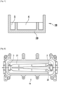
Fig. 1 is a top view of a rectangular fluid distribution layer 1 which has an approximate rectangular shape. The fluid distribution layer 1 is a component of a cooling structure. Aninlet 2 for a cooling fluid and anoutlet 3 are arranged at opposite sides of the fluid distribution layer 1. Theinlet 2 is positioned in an elongatedinner area 4. An elongatedouter area 5 is provided with twoside arms inner area 4. Abarrier 8 separates theinner area 4 from theouter area 5. In the embodiment ofFig. 1 thebarrier 8 has a V shape. Along the longitudinal direction, which extends between the inlet and the outlet, the width of theinner area 4 decreases, whereas the width of theouter area 5 increases. Theinner area 4 and theouter area 5 are essentially symmetrical to a longitudinal axis, which extends between theinlet 2 and theoutlet 3. -
Fig. 2 shows afluid separation plate 9, which in the installed state is arranged on top of the fluid distribution layer 1. Thefluid separation plate 9 comprises three throughopenings 10, which are arranged in a row in longitudinal direction. The throughopenings 10 are placed along the centre of thefluid separation plate 9, so that they are in communication with theinner area 4 of the fluid distribution layer 1. In addition, further throughopenings 11 are arranged on both sides of the throughopenings 10. The throughopenings 10 and the further throughopenings 11 are arranged in parallel with each other. All throughopenings openings 10 in the middle are marked with a dot, the outer throughopenings 11 are marked with a cross. These signs symbolize the flow direction. A dot stands for cooling fluid flowing downward, out of the plane, whereas a cross stands for cooling fluid flowing downward, into the plane. The function of thefluid separation plate 9 is to distribute the cooling fluid between several power modules. In the illustrated example three power modules are present, which are arranged on top of the cooling structure. -
Fig. 3 shows across meander layer 12, which is positioned on top of thefluid separation plate 9. In this embodiment thecross meander plate 12 comprises three distinct andidentical meander areas 13, each having an approximate square shape. Eachmeander area 13 comprises meander structures, which are oriented in transverse direction. Themeander areas 13 are separated from each other by transverse separators. Cold cooling fluid from thefluid separation plate 9 goes upward and enters the middle of thecross meander layer 12, which is indicated by the dots. The middle part of thecross meander layer 12 is restricted by twoparallel barriers 14, which are represented by lines. Due to the meander structure the cold cooling fluid absorbs heat from thecross meander layer 12, which is made from metal, and is warmed up. The separators between themeander areas 13 and thebarriers 14 cause that cooling fluid which is between theparallel barriers 14 can only flow further upward. As indicated by the crosses, hot cooling fluid in both outer parts of thecross meander layer 12 flows downward to thefluid separation plate 9. It is noted that the width of both outer parts of thecross meander layer 12 is different, which means that thebarriers 14 are not arranged symmetrical to the centre line (longitudinal axis). -
Fig. 4 shows in total four cross meander layers, which are stacked one on another. The firstcross meander layer 12 has been described before. The secondcross meander layer 15 has a similar structure as the firstcross meander layer 12, except for the position of thebarriers 14. Theparallel barriers 14 of the firstcross meander layer 12 are shifted a certain amount from the centre line to the right side, whereas thebarriers 14 of the secondcross meander layer 15 are shifted a certain amount from the centre line to the left side. A thirdcross meander layer 16 is identical to the firstcross meander layer 12 and a fourthcross meander layer 17 is identical to the secondcross meander layer 15. As the position of thebarriers 14 is not symmetrical to the centre line and alternates from one layer to the following cooling fluid is forced to mix and to go upwards and downwards. The stacked layers 12, 15, 16, 17 create a 3D structure circuit. -
Fig. 5 shows anupper plate 18, which is placed on top of the fourthcross meander layer 17, which seals the cooling structure and which ensures a good thermal connection with the power modules. -
Fig. 6 is a sectional view along the flow direction of aninverter 22 which is configured to convert a DC voltage into an AC voltage. The arrow "V" denotes the vertical direction. The arrow "F" denotes the flow direction. Theinverter 22 comprises a DC link capacitor (not shown) configured to smooth the DC voltage. Conversion of the DC voltage into the AC voltage is performed by apower module 23 comprising abase plate 24 and a substrate 25 fixed on a top face of thebase plate 24. Thepower module 23 further comprises controllable switches, which aresemiconductor power components 26 supported by the substrate 25. Thepower module 23 comprises an electrically insulatinghousing 27 surrounding the substrate 25 and thesemiconductor power components 26, while a downward face of thebase plate 24 is uncovered. Thepower module 23 further comprises acooling structure 28 which is fixed at the bottom face of thebase plate 24. - A sectional view of a
fluid distribution layer 29, which is configured to guide the cooling fluid, is depicted below thepower module 23. Thefluid distribution layer 29 comprises aninlet 30 and anoutlet 31. In the sectional view thebarrier 8 between the inner area and the outer area is visible as well. The coolingstructure 28 has elongated side walls and is configured to be fixed to thepower module 23, so that stacked cross meander layers 12 are received in a cavity of the cooling structure. The coolingstructure 28 and theinverter 22 comprising thepower module 23 are fixed to each other and sealed. - The coolant is intended to cross
chambers 32 in the meander areas of the cross meander layers 12 along the direction of flow F perpendicular to the vertical direction V for flowing from theinlet 30 to theoutlet 31. Thechambers 32 are formed by holes and are distributed between several cross meander layers 12 stacked on one another along the vertical direction. Each layer comprises meander like structures, as shown inFig. 3 . The chambers are stacked in an offset manner, so that for flowing between twoconsecutive chambers 32 the cooling fluid has to pass through one chamber of anothercross meander layer 12. In order to allow the flow of coolant between chambers of different layers, eachchamber 32 overlaps with chambers of an adjacent layer. The overlap between twochambers 32 of adjacent layers forms a cooling fluid aperture allowing coolant communication between these twochambers 32. When the cooling fluid flows through the cross meander layers 12, heat which is generated by thesemiconductor power components 26 is dissipated from thebase plate 24. -
Fig. 7 is a sectional view of the coolingstructure 28 shown inFig. 6 perpendicular to the flow direction. Thebarrier 8 separates theinner area 4 from twoouter areas 5. -
Fig. 8 shows a second embodiment of afluid distribution layer 19, which is similar to the fluid distribution layer 1. Thefluid distribution layer 19 has aninlet 2, anoutlet 3, an elongatedinner area 20, which is surrounded by anouter area 21. In contrast with the first embodiment the widths of theinner area 20 decrease stepwise from the inlet to the outlet. Theinner area 20 comprises three regions, which are symmetrical with regard to the centre line. The widths of these regions decrease from theinlet 2 to theoutlet 3. -
Fig. 9 shows anautomotive vehicle 33, comprisingwheels 34 and anelectric drive 35 configured to drive one or more wheels directly or indirectly. Thevehicle 33 comprises aDC voltage source 36, such as a battery, for electrically powering theelectric drive 35. TheDC voltage source 36 is configured to provide a DC voltage E. - The
electric drive 35 comprises anelectric motor 37 and aninverter 38 configured to drive theelectric motor 37 by supplying electric power. In this embodiment, theelectric motor 37 is a rotary electric motor comprising stator phases. In the described example, theelectric motor 37 is a three-phase electric motor comprising three stator phases. - The
inverter 38 comprises input terminals IT+, IT- connected to theDC voltage source 36 so that the DC voltage E is present at the input terminals IT+, IT-. More precisely, the input terminals IT+, IT- include a positive input terminal IT+ - connected to a positive terminal of the
DC voltage source 36 and a negative input terminal IT- connected to a negative terminal of the DC voltage source 106 and to an electrical ground GND. - The
inverter 38 further comprises output terminals OT connected to theelectric motor 37. An AC voltage is intended to be present at the output terminals OT for powering theelectric motor 37. The AC voltage may be a single or a multiphase AC voltage. In the described example where theelectric motor 37 is a three-phase electric motor, the AC voltage is a three-phase AC voltage. - The
inverter 38 further comprises controllable switches Q, Q', called main switches, connected to the input terminals IT+, IT- and to the output terminals OT. The main switches Q, Q' are semiconductor switches comprising for example transistors. Each main switch Q, Q' comprises for example one amongst: a Metal Oxide Semiconductor Field Effect Transistor (MOSFET), an Insulated Gate Bipolar Transistor (IGBT) and a Silicon Carbide MOSFET (SiC MOSFET). These switches Q, Q' correspond to thesemiconductor power components 26 ofFig. 6 . In the described embodiment, theinverter 38 comprisesswitch elements 39 respectively associated to the stator phases of theelectric motor 37. Eachswitch element 39 comprises a high side (HS) main switch Q' connected to the positive input terminal IT+ and a low side (LS) main switch Q connected to the negative input terminal IT. The HS main switch Q' and the LS main switch Q are connected to each other at a middle point connected to the output terminal OT connected to the associated stator phase of theelectric motor 37. - Each
switch element 39 is intended to be controlled to commute between two configurations. In the first one, called high side (HS) configuration, the HS main switch Q' is closed (on) and the LS main switch Q is open (off) so that the DC voltage E is essentially applied to the associated stator phase. In the second one, called low side (LS) configuration, the HS main switch Q' is open (off) and the LS main switch Q is closed (on) so that a zero voltage is essentially applied to the associated stator phase. - The
inverter 38 further comprises acontrol device 40 configured to control the main switches Q, Q' such that the main switches Q, Q' convert the DC voltage E into the AC voltage. In the described example, thecontrol device 40 is configured to commute eachswitch element 39 between the two configurations mentioned above. Thepower module 23 could implement, for example, one of theswitch elements 39 or all theswitch elements 39. - It will be noted that the invention is not limited to the embodiments described above. It will indeed appear to those skilled in the art that various modifications can be made to the embodiments described above, in the light of the teaching which has just been disclosed.
Claims (14)
- Cooling structure (28), comprising:- a fluid distribution layer (1, 19, 29) with- a first opening and a second opening for a cooling fluid, which are arranged at opposite sides of the fluid distribution layer (1, 19, 29),- an elongated inner area (4, 20), in which the first opening is positioned,- an elongated outer area (5, 21), in which the second opening is positioned, with two side arms (6, 7), which partly surround the inner area (4, 20),- a barrier (8) separating the inner area (4, 20) and the outer area (5, 21), wherein the width of the inner area (4, 20) decreases along a direction from the first opening to the second opening.
- Cooling structure according to claim 1, wherein the first opening is an inlet (2) for the cooling fluid and the second opening is an outlet (3) or vice versa.
- Cooling structure according to claim 1 or 2, wherein the width of the outer area (5, 21) increases along a direction from the first opening to the second opening.
- Cooling structure according to any of the preceding claims, wherein the barrier (8) has a U shape or a V shape.
- Cooling structure according to any of the preceding claims, wherein the width of the inner area (4, 20) decreases stepwise.
- Cooling structure according to any of the preceding claims, wherein outer edges of the inner area (4, 20) are inclined to an axis from the first opening, in particular the inlet (2), to the second opening, in particular the outlet (3).
- Cooling structure according to any of the preceding claims, wherein the inner area (4, 20) and the outer area (5, 21) are essentially symmetrical to an axis from the first opening, in particular the inlet (2), to the second opening, in particular the outlet (3).
- Cooling structure according any of the preceding claims, wherein a fluid separation plate (9) is arranged between the fluid distribution layer (1, 19, 29) and stacked layers (12, 15, 16, 17) of the cooling structure (28), wherein the fluid separation plate (9) comprises through openings (10, 11), which are either in communication with the inner area (4, 20) or the outer area (5, 21).
- Cooling structure according to claim 8, wherein the through openings (10, 11) are formed as slits arranged along a direction from the inlet (2) to the outlet (3).
- Cooling structure according any of the preceding claims, comprising several layers (12, 15, 16, 17) and a network of local chambers (32) distributed between the several layers (12, 15, 16, 17) stacked one on another according to a stacking direction, wherein each local chamber (32) comprises at least two apertures, of which at least one is in communication with a local chamber (32) of another of the layers (12, 15, 16, 17), wherein each local chamber (32) comprises one or several meander-like structures blocking any direct path in the local chamber (32) between the two apertures.
- Electric power converter, in particular inverter (38), comprising:- a power module (23) with semiconductor power components (26), arranged on a substrate (25),- a base plate (24), on which the substrate (25) is arranged, and- a cooling structure (28) according to any of claims 1 to 10, arranged below the base plate (24).
- Electric power converter according to claim 11, wherein the inverter (38) is a multiphase inverter, wherein the through openings (10, 11) in the fluid separation plate (9), in particular the slits, are arranged in rows, wherein the number of rows corresponds to the number of phases.
- Electric power converter according to claim 11 or 12, wherein the cooling structure (28) is received in a housing (27) with an inlet (30) and an outlet (31) for cooling fluid.
- Vehicle (33), comprising a battery, a multiphase electric motor (37) configured to drive at least one wheel and an electric power converter according to any of claims 11 to 13.
Applications Claiming Priority (1)
| Application Number | Priority Date | Filing Date | Title |
|---|---|---|---|
| FR2305474A FR3149373B1 (en) | 2023-06-01 | 2023-06-01 | Cooling structure, electric power converter comprising such a cooling structure and vehicle |
Publications (2)
| Publication Number | Publication Date |
|---|---|
| EP4471848A1 true EP4471848A1 (en) | 2024-12-04 |
| EP4471848B1 EP4471848B1 (en) | 2025-09-10 |
Family
ID=87889651
Family Applications (1)
| Application Number | Title | Priority Date | Filing Date |
|---|---|---|---|
| EP24178045.1A Active EP4471848B1 (en) | 2023-06-01 | 2024-05-24 | Cooling structure, electric power converter comprising such cooling structure and vehicle |
Country Status (6)
| Country | Link |
|---|---|
| US (1) | US20240407143A1 (en) |
| EP (1) | EP4471848B1 (en) |
| JP (1) | JP2024173837A (en) |
| KR (1) | KR20240172692A (en) |
| CN (1) | CN119072075A (en) |
| FR (1) | FR3149373B1 (en) |
Citations (3)
| Publication number | Priority date | Publication date | Assignee | Title |
|---|---|---|---|---|
| EP2416483A2 (en) | 2010-06-21 | 2012-02-08 | Hitachi Automotive Systems, Ltd. | Power semiconductor device and power conversion device |
| WO2012028144A2 (en) * | 2010-08-31 | 2012-03-08 | Danfoss Drives A/S | A cooling device with at least two coolant flow modules |
| WO2022248427A1 (en) | 2021-05-27 | 2022-12-01 | Valeo Eautomotive Germany Gmbh | Cooling structure, power module comprising such a cooling structure, electrical power converter, such as an inverter, comprising such a power module |
Family Cites Families (4)
| Publication number | Priority date | Publication date | Assignee | Title |
|---|---|---|---|---|
| JP2006313054A (en) * | 2005-04-04 | 2006-11-16 | Soichi Mizui | Plate-shaped heat exchanger and radiator |
| US20110226448A1 (en) * | 2008-08-08 | 2011-09-22 | Mikros Manufacturing, Inc. | Heat exchanger having winding channels |
| US20130032230A1 (en) * | 2010-04-13 | 2013-02-07 | Danfoss Silicon Power Gmbh | Flow distributor |
| JP7159617B2 (en) * | 2018-05-25 | 2022-10-25 | 富士電機株式会社 | Cooling device, semiconductor module, vehicle and manufacturing method |
-
2023
- 2023-06-01 FR FR2305474A patent/FR3149373B1/en active Active
-
2024
- 2024-05-24 EP EP24178045.1A patent/EP4471848B1/en active Active
- 2024-05-28 KR KR1020240069029A patent/KR20240172692A/en active Pending
- 2024-05-29 CN CN202410679458.8A patent/CN119072075A/en active Pending
- 2024-05-31 JP JP2024089491A patent/JP2024173837A/en active Pending
- 2024-05-31 US US18/679,880 patent/US20240407143A1/en active Pending
Patent Citations (3)
| Publication number | Priority date | Publication date | Assignee | Title |
|---|---|---|---|---|
| EP2416483A2 (en) | 2010-06-21 | 2012-02-08 | Hitachi Automotive Systems, Ltd. | Power semiconductor device and power conversion device |
| WO2012028144A2 (en) * | 2010-08-31 | 2012-03-08 | Danfoss Drives A/S | A cooling device with at least two coolant flow modules |
| WO2022248427A1 (en) | 2021-05-27 | 2022-12-01 | Valeo Eautomotive Germany Gmbh | Cooling structure, power module comprising such a cooling structure, electrical power converter, such as an inverter, comprising such a power module |
Also Published As
| Publication number | Publication date |
|---|---|
| FR3149373A1 (en) | 2024-12-06 |
| CN119072075A (en) | 2024-12-03 |
| US20240407143A1 (en) | 2024-12-05 |
| EP4471848B1 (en) | 2025-09-10 |
| JP2024173837A (en) | 2024-12-12 |
| FR3149373B1 (en) | 2025-05-16 |
| KR20240172692A (en) | 2024-12-10 |
Similar Documents
| Publication | Publication Date | Title |
|---|---|---|
| US10985089B2 (en) | Semiconductor cooling arrangement | |
| CN101681898B (en) | Cooling structure for semiconductor elements | |
| CN108306524B (en) | Power modules for inverter switches with gate coils shielding eddy currents | |
| CN100416804C (en) | power stack | |
| EP3076428B1 (en) | Cooler and cooler fixing method | |
| US20070165376A1 (en) | Three phase inverter power stage and assembly | |
| US11355629B2 (en) | Semiconductor device and power converter | |
| US20240230247A1 (en) | Cooling structure, power module comprising such a cooling structure, electrical power converter, such as an inverter, comprising such a power module | |
| CN115149772A (en) | Power module for inverter and inverter including the same | |
| EP3598490A1 (en) | Power module | |
| CN104218829A (en) | Inverted unit | |
| CN113728546A (en) | Power conversion device | |
| JP3793700B2 (en) | Power converter | |
| EP4471848B1 (en) | Cooling structure, electric power converter comprising such cooling structure and vehicle | |
| US6584001B2 (en) | Power converter module | |
| CN111034007B (en) | Power conversion device | |
| US20230301008A1 (en) | Switch module for an inverter, inverter with several such switch modules and vehicle with the inverter | |
| WO2024107513A1 (en) | Power electronics package with dual-single side cooling water jacket | |
| US20210407880A1 (en) | Power module for operating an electric vehicle drive with improved temperature determination of the power semiconductors | |
| US20250201665A1 (en) | Power device and method for assembling a power device |
Legal Events
| Date | Code | Title | Description |
|---|---|---|---|
| PUAI | Public reference made under article 153(3) epc to a published international application that has entered the european phase |
Free format text: ORIGINAL CODE: 0009012 |
|
| STAA | Information on the status of an ep patent application or granted ep patent |
Free format text: STATUS: REQUEST FOR EXAMINATION WAS MADE |
|
| 17P | Request for examination filed |
Effective date: 20240524 |
|
| AK | Designated contracting states |
Kind code of ref document: A1 Designated state(s): AL AT BE BG CH CY CZ DE DK EE ES FI FR GB GR HR HU IE IS IT LI LT LU LV MC ME MK MT NL NO PL PT RO RS SE SI SK SM TR |
|
| GRAP | Despatch of communication of intention to grant a patent |
Free format text: ORIGINAL CODE: EPIDOSNIGR1 |
|
| STAA | Information on the status of an ep patent application or granted ep patent |
Free format text: STATUS: GRANT OF PATENT IS INTENDED |
|
| INTG | Intention to grant announced |
Effective date: 20250425 |
|
| RIN1 | Information on inventor provided before grant (corrected) |
Inventor name: KUNTZE, FRIEDHELM Inventor name: ANBAZHAGAN, ARUNPRASAD Inventor name: KHOT, SHAUNAK Inventor name: HECHT, MICHAEL Inventor name: SMIT, ARNOUD Inventor name: FAKES, MICHEL |
|
| GRAS | Grant fee paid |
Free format text: ORIGINAL CODE: EPIDOSNIGR3 |
|
| GRAA | (expected) grant |
Free format text: ORIGINAL CODE: 0009210 |
|
| STAA | Information on the status of an ep patent application or granted ep patent |
Free format text: STATUS: THE PATENT HAS BEEN GRANTED |
|
| AK | Designated contracting states |
Kind code of ref document: B1 Designated state(s): AL AT BE BG CH CY CZ DE DK EE ES FI FR GB GR HR HU IE IS IT LI LT LU LV MC ME MK MT NL NO PL PT RO RS SE SI SK SM TR |
|
| REG | Reference to a national code |
Ref country code: GB Ref legal event code: FG4D |
|
| REG | Reference to a national code |
Ref country code: CH Ref legal event code: EP |
|
| REG | Reference to a national code |
Ref country code: DE Ref legal event code: R096 Ref document number: 602024000623 Country of ref document: DE |
|
| REG | Reference to a national code |
Ref country code: IE Ref legal event code: FG4D |
|
| REG | Reference to a national code |
Ref country code: DE Ref legal event code: R079 Ref document number: 602024000623 Country of ref document: DE Free format text: PREVIOUS MAIN CLASS: H01L0023467000 Ipc: H10W0040430000 |
|
| PG25 | Lapsed in a contracting state [announced via postgrant information from national office to epo] |
Ref country code: NO Free format text: LAPSE BECAUSE OF FAILURE TO SUBMIT A TRANSLATION OF THE DESCRIPTION OR TO PAY THE FEE WITHIN THE PRESCRIBED TIME-LIMIT Effective date: 20251210 |
|
| REG | Reference to a national code |
Ref country code: LT Ref legal event code: MG9D |
|
| PG25 | Lapsed in a contracting state [announced via postgrant information from national office to epo] |
Ref country code: FI Free format text: LAPSE BECAUSE OF FAILURE TO SUBMIT A TRANSLATION OF THE DESCRIPTION OR TO PAY THE FEE WITHIN THE PRESCRIBED TIME-LIMIT Effective date: 20250910 |
|
| REG | Reference to a national code |
Ref country code: NL Ref legal event code: MP Effective date: 20250910 |
|
| PG25 | Lapsed in a contracting state [announced via postgrant information from national office to epo] |
Ref country code: HR Free format text: LAPSE BECAUSE OF FAILURE TO SUBMIT A TRANSLATION OF THE DESCRIPTION OR TO PAY THE FEE WITHIN THE PRESCRIBED TIME-LIMIT Effective date: 20250910 |
|
| PG25 | Lapsed in a contracting state [announced via postgrant information from national office to epo] |
Ref country code: GR Free format text: LAPSE BECAUSE OF FAILURE TO SUBMIT A TRANSLATION OF THE DESCRIPTION OR TO PAY THE FEE WITHIN THE PRESCRIBED TIME-LIMIT Effective date: 20251211 |
|
| PG25 | Lapsed in a contracting state [announced via postgrant information from national office to epo] |
Ref country code: SE Free format text: LAPSE BECAUSE OF FAILURE TO SUBMIT A TRANSLATION OF THE DESCRIPTION OR TO PAY THE FEE WITHIN THE PRESCRIBED TIME-LIMIT Effective date: 20250910 |
|
| PG25 | Lapsed in a contracting state [announced via postgrant information from national office to epo] |
Ref country code: LV Free format text: LAPSE BECAUSE OF FAILURE TO SUBMIT A TRANSLATION OF THE DESCRIPTION OR TO PAY THE FEE WITHIN THE PRESCRIBED TIME-LIMIT Effective date: 20250910 |
|
| PG25 | Lapsed in a contracting state [announced via postgrant information from national office to epo] |
Ref country code: BG Free format text: LAPSE BECAUSE OF FAILURE TO SUBMIT A TRANSLATION OF THE DESCRIPTION OR TO PAY THE FEE WITHIN THE PRESCRIBED TIME-LIMIT Effective date: 20250910 Ref country code: PL Free format text: LAPSE BECAUSE OF FAILURE TO SUBMIT A TRANSLATION OF THE DESCRIPTION OR TO PAY THE FEE WITHIN THE PRESCRIBED TIME-LIMIT Effective date: 20250910 |
|
| PG25 | Lapsed in a contracting state [announced via postgrant information from national office to epo] |
Ref country code: RS Free format text: LAPSE BECAUSE OF FAILURE TO SUBMIT A TRANSLATION OF THE DESCRIPTION OR TO PAY THE FEE WITHIN THE PRESCRIBED TIME-LIMIT Effective date: 20251210 |
|
| PG25 | Lapsed in a contracting state [announced via postgrant information from national office to epo] |
Ref country code: ES Free format text: LAPSE BECAUSE OF FAILURE TO SUBMIT A TRANSLATION OF THE DESCRIPTION OR TO PAY THE FEE WITHIN THE PRESCRIBED TIME-LIMIT Effective date: 20250910 |
|
| REG | Reference to a national code |
Ref country code: AT Ref legal event code: MK05 Ref document number: 1836870 Country of ref document: AT Kind code of ref document: T Effective date: 20250910 |
|
| PG25 | Lapsed in a contracting state [announced via postgrant information from national office to epo] |
Ref country code: NL Free format text: LAPSE BECAUSE OF FAILURE TO SUBMIT A TRANSLATION OF THE DESCRIPTION OR TO PAY THE FEE WITHIN THE PRESCRIBED TIME-LIMIT Effective date: 20250910 |
|
| PG25 | Lapsed in a contracting state [announced via postgrant information from national office to epo] |
Ref country code: SM Free format text: LAPSE BECAUSE OF FAILURE TO SUBMIT A TRANSLATION OF THE DESCRIPTION OR TO PAY THE FEE WITHIN THE PRESCRIBED TIME-LIMIT Effective date: 20250910 |
|
| PG25 | Lapsed in a contracting state [announced via postgrant information from national office to epo] |
Ref country code: AT Free format text: LAPSE BECAUSE OF FAILURE TO SUBMIT A TRANSLATION OF THE DESCRIPTION OR TO PAY THE FEE WITHIN THE PRESCRIBED TIME-LIMIT Effective date: 20250910 |
|
| PG25 | Lapsed in a contracting state [announced via postgrant information from national office to epo] |
Ref country code: IT Free format text: LAPSE BECAUSE OF FAILURE TO SUBMIT A TRANSLATION OF THE DESCRIPTION OR TO PAY THE FEE WITHIN THE PRESCRIBED TIME-LIMIT Effective date: 20250910 |
|
| PG25 | Lapsed in a contracting state [announced via postgrant information from national office to epo] |
Ref country code: IS Free format text: LAPSE BECAUSE OF FAILURE TO SUBMIT A TRANSLATION OF THE DESCRIPTION OR TO PAY THE FEE WITHIN THE PRESCRIBED TIME-LIMIT Effective date: 20260110 |
|
| PG25 | Lapsed in a contracting state [announced via postgrant information from national office to epo] |
Ref country code: CZ Free format text: LAPSE BECAUSE OF FAILURE TO SUBMIT A TRANSLATION OF THE DESCRIPTION OR TO PAY THE FEE WITHIN THE PRESCRIBED TIME-LIMIT Effective date: 20250910 Ref country code: PT Free format text: LAPSE BECAUSE OF FAILURE TO SUBMIT A TRANSLATION OF THE DESCRIPTION OR TO PAY THE FEE WITHIN THE PRESCRIBED TIME-LIMIT Effective date: 20260112 |
|
| PG25 | Lapsed in a contracting state [announced via postgrant information from national office to epo] |
Ref country code: EE Free format text: LAPSE BECAUSE OF FAILURE TO SUBMIT A TRANSLATION OF THE DESCRIPTION OR TO PAY THE FEE WITHIN THE PRESCRIBED TIME-LIMIT Effective date: 20250910 Ref country code: SK Free format text: LAPSE BECAUSE OF FAILURE TO SUBMIT A TRANSLATION OF THE DESCRIPTION OR TO PAY THE FEE WITHIN THE PRESCRIBED TIME-LIMIT Effective date: 20250910 |