EP4471819A1 - Direct-current limiter and direct-current interruption system - Google Patents
Direct-current limiter and direct-current interruption system Download PDFInfo
- Publication number
- EP4471819A1 EP4471819A1 EP22923754.0A EP22923754A EP4471819A1 EP 4471819 A1 EP4471819 A1 EP 4471819A1 EP 22923754 A EP22923754 A EP 22923754A EP 4471819 A1 EP4471819 A1 EP 4471819A1
- Authority
- EP
- European Patent Office
- Prior art keywords
- current
- direct
- inductor
- interrupt
- line
- Prior art date
- Legal status (The legal status is an assumption and is not a legal conclusion. Google has not performed a legal analysis and makes no representation as to the accuracy of the status listed.)
- Pending
Links
Images


Classifications
-
- H—ELECTRICITY
- H01—ELECTRIC ELEMENTS
- H01H—ELECTRIC SWITCHES; RELAYS; SELECTORS; EMERGENCY PROTECTIVE DEVICES
- H01H33/00—High-tension or heavy-current switches with arc-extinguishing or arc-preventing means
- H01H33/02—Details
- H01H33/59—Circuit arrangements not adapted to a particular application of the switch and not otherwise provided for, e.g. for ensuring operation of the switch at a predetermined point in the AC cycle
- H01H33/596—Circuit arrangements not adapted to a particular application of the switch and not otherwise provided for, e.g. for ensuring operation of the switch at a predetermined point in the AC cycle for interrupting DC
-
- H—ELECTRICITY
- H02—GENERATION; CONVERSION OR DISTRIBUTION OF ELECTRIC POWER
- H02H—EMERGENCY PROTECTIVE CIRCUIT ARRANGEMENTS
- H02H3/00—Emergency protective circuit arrangements for automatic disconnection directly responsive to an undesired change from normal electric working condition with or without subsequent reconnection ; integrated protection
- H02H3/08—Emergency protective circuit arrangements for automatic disconnection directly responsive to an undesired change from normal electric working condition with or without subsequent reconnection ; integrated protection responsive to excess current
- H02H3/087—Emergency protective circuit arrangements for automatic disconnection directly responsive to an undesired change from normal electric working condition with or without subsequent reconnection ; integrated protection responsive to excess current for DC applications
-
- H—ELECTRICITY
- H02—GENERATION; CONVERSION OR DISTRIBUTION OF ELECTRIC POWER
- H02H—EMERGENCY PROTECTIVE CIRCUIT ARRANGEMENTS
- H02H7/00—Emergency protective circuit arrangements specially adapted for specific types of electric machines or apparatus or for sectionalised protection of cable or line systems, and effecting automatic switching in the event of an undesired change from normal working conditions
- H02H7/001—Emergency protective circuit arrangements specially adapted for specific types of electric machines or apparatus or for sectionalised protection of cable or line systems, and effecting automatic switching in the event of an undesired change from normal working conditions for superconducting apparatus, e.g. coils, lines, machines
-
- H—ELECTRICITY
- H01—ELECTRIC ELEMENTS
- H01F—MAGNETS; INDUCTANCES; TRANSFORMERS; SELECTION OF MATERIALS FOR THEIR MAGNETIC PROPERTIES
- H01F6/00—Superconducting magnets; Superconducting coils
- H01F6/06—Coils, e.g. winding, insulating, terminating or casing arrangements therefor
-
- H—ELECTRICITY
- H02—GENERATION; CONVERSION OR DISTRIBUTION OF ELECTRIC POWER
- H02H—EMERGENCY PROTECTIVE CIRCUIT ARRANGEMENTS
- H02H3/00—Emergency protective circuit arrangements for automatic disconnection directly responsive to an undesired change from normal electric working condition with or without subsequent reconnection ; integrated protection
- H02H3/02—Details
- H02H3/025—Disconnection after limiting, e.g. when limiting is not sufficient or for facilitating disconnection
-
- H—ELECTRICITY
- H02—GENERATION; CONVERSION OR DISTRIBUTION OF ELECTRIC POWER
- H02H—EMERGENCY PROTECTIVE CIRCUIT ARRANGEMENTS
- H02H9/00—Emergency protective circuit arrangements for limiting excess current or voltage without disconnection
- H02H9/02—Emergency protective circuit arrangements for limiting excess current or voltage without disconnection responsive to excess current
- H02H9/023—Current limitation using superconducting elements
-
- Y—GENERAL TAGGING OF NEW TECHNOLOGICAL DEVELOPMENTS; GENERAL TAGGING OF CROSS-SECTIONAL TECHNOLOGIES SPANNING OVER SEVERAL SECTIONS OF THE IPC; TECHNICAL SUBJECTS COVERED BY FORMER USPC CROSS-REFERENCE ART COLLECTIONS [XRACs] AND DIGESTS
- Y02—TECHNOLOGIES OR APPLICATIONS FOR MITIGATION OR ADAPTATION AGAINST CLIMATE CHANGE
- Y02E—REDUCTION OF GREENHOUSE GAS [GHG] EMISSIONS, RELATED TO ENERGY GENERATION, TRANSMISSION OR DISTRIBUTION
- Y02E40/00—Technologies for an efficient electrical power generation, transmission or distribution
- Y02E40/60—Superconducting electric elements or equipment; Power systems integrating superconducting elements or equipment
Definitions
- the present invention relates to a direct-current limiter and a direct-current circuit breaker system.
- Direct-current circuits unlike alternating-current circuits, have no skin effect and are excellent in power transmission efficiency. Therefore, direct-current circuits are widely used in power networks for trains and similar devices.
- an accident such as a short circuit occurs in a direct-current circuit
- the current increases over time, making it more difficult to interrupt the circuit in proportion to the elapsed time. For this reason, in the event of an accident, it is necessary to interrupt the direct-current circuit at high speed. Therefore, in order to interrupt the direct-current circuit at high speed, a direct-current high-speed circuit breaker (HSCB) has been used. This breaker generates an explosive arc by opening the contacts to generate a voltage higher than the power supply voltage and limit and interrupt the fault current (see, for example, Non-Patent Literature 1).
- HSCB direct-current high-speed circuit breaker
- Non-Patent Literature 1 Nobumoto Tooya, Hiroshi Sasaki, Tomohiro Nakata, "High Speed Circuit Breaker for Railway Substation,” Mitsubishi Denki giho, 2017, Vol. 91, No. 11, p. 39-43
- Non-Patent Literature 1 has a problem that, in the case of an accident where the current rises quickly, the current limiting does not occur in time, and the circuit breaker may fail to interrupt the current.
- the present invention has been made in light of such problems, and an object thereof is to provide a direct-current limiter that can reliably limit the current even in the case of an accident where the current rises quickly and a direct-current circuit breaker system that can more reliably interrupt a direct-current line.
- a direct-current limiter for limiting a direct current in order to interrupt the direct current flowing through a direct-current line, including: an LC parallel circuit inserted in the direct-current line having a first inductor and a capacitor connected in parallel to each other; and a second inductor inserted in the direct-current line and connected in series to the LC parallel circuit.
- the direct-current limiter operates according to the following principle.
- a constant direct current flows through the direct-current line in a normal state.
- a current flows only through the first inductor.
- a current also flows through the second inductor inserted into the direct-current line and connected in series to the LC parallel circuit.
- the direct-current limiter it is preferable that at least one of the first inductor and the second inductor is made of superconducting coils.
- the resistance values of the first inductor and the second inductor to the direct current can be made almost zero. Therefore, almost no voltage is generated in the LC parallel circuit and the second inductor in the normal state, and power loss can be made almost zero.
- the amplitude of the increase and decrease in the current value due to the transient phenomenon that occurs in the event of an accident can be increased, and the minimum value of the current (current at the time of current limiting) can be reduced.
- the first inductor can be made smaller and lighter by making the first inductor using a superconducting coil.
- a direct-current circuit breaker system includes the direct-current limiter according to the present invention and an interrupting unit configured to interrupt the current flowing through the direct-current line when a passing current that has passed through the LC parallel circuit and the second inductor satisfies a predetermined condition.
- the direct-current circuit breaker system can reliably interrupt the current, for example, by the direct-current limiter interrupting the current flowing through the direct-current line when the passing current that has passed through the LC parallel circuit and the second inductor satisfies a predetermined condition, such as when the passing current is limited by the direct-current limiter. Therefore, in the case of an accident where the current rises quickly, the direct-current line can be interrupted by limiting the current more reliably.
- the direct-current circuit breaker system can prevent an interruption failure because the direct-current limiter can suppress the maximum current Imax in the event of an accident and can ensure a time margin until the current is interrupted.
- the interrupting unit may be any type capable of interrupting a direct-current line, but it is preferably made of a type capable of effectively interrupting a current that changes due to a transient phenomenon.
- the interrupting unit may be configured to interrupt the current flowing through the direct-current line when the passing current becomes equal to or less than a predetermined current value.
- the current can be interrupted when the passing current is limited.
- the interrupting unit preferably interrupts the current flowing through the direct-current line when the passing current becomes zero amperes. This makes it possible to prevent the occurrence of an arc discharge when the current is interrupted.
- the interrupting unit is made of an alternating-current circuit breaker.
- the interrupting unit may be configured to interrupt the current flowing through the direct-current line when the passing current varies by a predetermined value or more from a current value of the direct current. In this case, it is possible to detect the occurrence of an accident due to fluctuations in the passing current and interrupt the current.
- the interrupting unit may be configured to interrupt the current flowing through the direct-current line when the passing current repeatedly increases and decreases with a predetermined amplitude or more. In this case, it is possible to detect the occurrence of an accident due to the occurrence of a transient phenomenon and interrupt the current.
- a direct-current limiter that can reliably limit the current even in the case of an accident where the current rises quickly, and a direct-current circuit breaker system that can more reliably interrupt a direct-current line.
- FIGS. 1 to 7 show a direct-current limiter and a direct-current circuit breaker system according to an embodiment of the present invention.
- a direct-current circuit breaker system 10 is a direct-current circuit breaker system for interrupting a direct current flowing through a direct-current line 1, and includes a direct-current limiter 11 and an interrupting unit 12.
- the direct-current limiter 11 includes an LC parallel circuit 11a including a first inductor 21 and a capacitor 22, and a second inductor 23.
- the LC parallel circuit 11a is inserted into the direct-current line 1, and the first inductor 21 and the capacitor 22 are connected in parallel to each other.
- the second inductor 23 is inserted into the direct-current line 1 and connected in series to the LC parallel circuit 11a.
- the second inductor 23 may be connected to the upstream side or the downstream side of the direct current flowing through the direct-current line 1 with respect to the LC parallel circuit 11a.
- the first inductor 21 has a larger inductance than the second inductor 23.
- the first inductor 21 and the second inductor 23 preferably have a smaller resistance value to direct current, and are particularly preferably made of superconducting coils.
- the interrupting unit 12 is inserted in the direct-current line 1.
- the interrupting unit 12 is connected on the downstream side of the direct current flowing through the direct-current line 1 with respect to the LC parallel circuit 11a and the second inductor 23.
- the interrupting unit 12 is configured to interrupt the current flowing through the direct-current line 1 when the passing current that has passed through the LC parallel circuit 11a and the second inductor 23 satisfies a predetermined condition.
- the interrupting unit 12 may be any type capable of interrupting the direct-current line 1, but is preferably made of a type capable of effectively interrupting a changing current.
- the direct-current limiter 11 and the direct-current circuit breaker system 10 operate according to the following principle.
- a constant direct current flows through the direct-current line 1 in a normal state.
- a current flows only through the first inductor 21.
- a current also flows through the second inductor 23 connected in series to the LC parallel circuit 11a.
- both the first inductor 21 and the second inductor 23 are made of superconducting coils, it is possible to make the resistance value to the direct current almost zero, and to make power loss almost zero. Also, even if either the first inductor 21 or the second inductor 23 is a superconducting coil, it is possible to suppress power loss.
- the amplitude of the increase and decrease in the current value due to the transient phenomenon occurring at the time of the accident can be increased, and the minimum value of the current (current at the time of current limiting) can be reduced.
- the current can be reliably interrupted by configuring the interrupting unit 12 so that the current is interrupted, for example, when any of the following conditions are met.
- the current can be interrupted when the passing current is limited. In particular, by interrupting the current when the passing current becomes zero amperes, it is possible to prevent arc discharge from occurring when the current is interrupted. By preventing arc discharge, it is possible to prevent wear on the contacts and arc chutes, noise during interruption, and damage to peripheral devices. In addition, since it is not necessary to secure an arc space, it is possible to reduce the size of the interrupting unit 12. In this case, an alternating-current circuit breaker can be used as the interrupting unit 12. In the case of condition 2, it is possible to detect the occurrence of an accident due to fluctuations in the passing current and interrupt the current. In the case of condition 3, it is possible to detect the occurrence of an accident due to the occurrence of a transient phenomenon and interrupt the current.
- the direct-current circuit breaker system 10 can reliably interrupt the current by the interrupting unit 12 interrupting the current flowing through the direct-current line 1 when the passing current that has passed through the LC parallel circuit 11a and the second inductor 23 satisfies the predetermined conditions such as conditions 1 to 3. Therefore, even in the case of an accident where the current rises quickly, the direct-current line 1 can be interrupted by limiting the current more reliably.
- the direct-current circuit breaker system 10 can prevent an interruption failure because the direct-current limiter 11 can suppress the maximum current Imax in the event of an accident and can ensure a time margin until the current is interrupted.
- the operation of the direct-current limiter 11 and the direct-current circuit breaker system 10 was analyzed using commercially available analysis software "MATLAB ® /Simulink (manufactured by MathWorks, Inc.)".
- the circuit used for the analysis is shown in FIG. 3 .
- the circuit in FIG. 3 is a circuit in which a variable resistor 2 is inserted in the direct-current line 1 of the circuit shown in FIG. 1 to represent the load of the power supply destination in a normal state and the load in the event of an accident such as a short circuit.
- FIG. 4 An analysis of the interruption operation was performed using current waveform data simulating a ground fault accident as accident data.
- the current waveform data used is shown in FIG. 4 .
- the rate of change of current over time dI/dt is constant at 80 kA/sec, and the current rises from a steady current of 100 A to 16000 A 200 msec after the occurrence of the accident. It was also assumed that the current would rise until the analysis was completed if the current was not interrupted.
- the data shown in FIG. 4 was input to the variable resistor 2.
- the voltage E of the power supply 3 was set to 1500 V, the inductance L 1 of the first inductor 21 to 1 H, the capacitance C of the capacitor 22 to 4.5 mF, and the inductance L 2 of the second inductor 23 to 0.03 H.
- the current was interrupted by the interrupting unit 12 when the passing current that has passed through the interrupting unit 12 became zero amperes.
- the resistance of the interrupting unit 12 was 0.001 ⁇ , and the conductance was 10 -6 S.
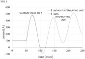
- FIG. 5 shows the analyzed current waveform at the time of the accident. Note that FIG. 5 also shows the case where there is no interrupting unit 12 (where the current is not interrupted). As shown in FIG. 5 , it was confirmed that the current value temporarily increases due to the short circuit accident, but the current decreases due to the transient phenomenon, and the current was reliably limited. It was also confirmed that the current was interrupted by the interrupting unit 12 the moment the passing current became zero amperes. Specifically, it was confirmed that the maximum current Imax was suppressed to 480 A. It was also confirmed that the current was interrupted within 100 msec (about 50 msec) after the accident occurred. Note that from the graph for the case where there is no interrupting unit 12, it was confirmed that the current value oscillates with the maximum current Imax suppressed due to the transient phenomenon. From this, it can be said that a time margin until interruption can be secured.
- the parameters of the inductance L 1 of the first inductor 21, the capacitance C of the capacitor 22, and the inductance L 2 of the second inductor 23 in the circuit were changed to analyze the current fluctuation.
- the data shown in FIG. 4 was used as the accident waveform data to be input to the variable resistor 2.
- the voltage E of the power supply 3 was set to 1500 V, and the interrupting unit 12 was not provided.
- Analysis was performed for three cases: a case where the inductance L 1 of the first inductor 21 was changed, a case where the capacitance C of the capacitor 22 was changed, and a case where the inductance L 2 of the second inductor 23 was changed.
- the values of the parameters used in the analysis for these three cases are shown in Table 1.
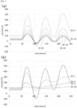
- FIG. 6(a) to 6(c) The current waveforms after the accident for the three cases shown in Table 1 are shown in FIG. 6(a) to 6(c) , respectively.
- FIG. 6(a) it was confirmed that the amplitude of the current due to the transient phenomenon becomes smaller as the inductance L 1 of the first inductor 21 increases. It was also confirmed that the period of the current due to the transient phenomenon does not change even if the inductance L 1 changes.
- FIG. 6(b) it was confirmed that the amplitude of the current due to the transient phenomenon becomes larger and the period becomes longer as the capacitance C of the capacitor 22 increases.
- FIG. 6(c) it was confirmed that the initial amplitude of the current due to the transient phenomenon becomes smaller and the period becomes longer as the inductance L 2 of the second inductor 23 increases.
- the data shown in FIG. 4 was used as the accident data to be input to the variable resistor 2.
- the voltage E of the power supply 3 was set to 1500 V
- the inductance L 1 of the first inductor 21 to 1H the capacitance C of the capacitor 22 to 4.5 mF
- the inductance L 2 of the second inductor 23 was 0.03 H.
- the interrupting unit 12 was not provided.
- FIGS. 7(a) and 7(b) The current waveforms after the accident in each case are shown in FIGS. 7(a) and 7(b) , respectively.
- FIG. 7(a) it was confirmed that the value of the constant current in the normal state becomes smaller and the amplitude of the current due to the transient phenomenon also becomes smaller as the resistance value of the first inductor 21 increases.
- FIG. 7(b) it was confirmed that the value of the constant current in the normal state becomes smaller and the amplitude of the current due to the transient phenomenon also becomes smaller as the resistance value of the second inductor 23 increases. It was also confirmed that the resistance of the second inductor 23 has a greater effect on the amplitude of the current due to the transient phenomenon than the resistance of the first inductor 21.
Landscapes
- Engineering & Computer Science (AREA)
- Power Engineering (AREA)
- Emergency Protection Circuit Devices (AREA)
Abstract
Description
- The present invention relates to a direct-current limiter and a direct-current circuit breaker system.
- Direct-current circuits, unlike alternating-current circuits, have no skin effect and are excellent in power transmission efficiency. Therefore, direct-current circuits are widely used in power networks for trains and similar devices. When an accident such as a short circuit occurs in a direct-current circuit, the current increases over time, making it more difficult to interrupt the circuit in proportion to the elapsed time. For this reason, in the event of an accident, it is necessary to interrupt the direct-current circuit at high speed. Therefore, in order to interrupt the direct-current circuit at high speed, a direct-current high-speed circuit breaker (HSCB) has been used. This breaker generates an explosive arc by opening the contacts to generate a voltage higher than the power supply voltage and limit and interrupt the fault current (see, for example, Non-Patent Literature 1).
- Non-Patent Literature 1: Nobumoto Tooya, Hiroshi Sasaki, Tomohiro Nakata, "High Speed Circuit Breaker for Railway Substation," Mitsubishi Denki giho, 2017, Vol. 91, No. 11, p. 39-43
- However, the direct-current high-speed circuit breaker described in Non-Patent
Literature 1 has a problem that, in the case of an accident where the current rises quickly, the current limiting does not occur in time, and the circuit breaker may fail to interrupt the current. - The present invention has been made in light of such problems, and an object thereof is to provide a direct-current limiter that can reliably limit the current even in the case of an accident where the current rises quickly and a direct-current circuit breaker system that can more reliably interrupt a direct-current line.
- To achieve the above object, a direct-current limiter according to the present invention is a direct-current limiter for limiting a direct current in order to interrupt the direct current flowing through a direct-current line, including: an LC parallel circuit inserted in the direct-current line having a first inductor and a capacitor connected in parallel to each other; and a second inductor inserted in the direct-current line and connected in series to the LC parallel circuit.
- The direct-current limiter according to the present invention operates according to the following principle. First, a constant direct current flows through the direct-current line in a normal state. At this time, in the LC parallel circuit inserted into the direct-current line, since no current flows through the capacitor, a current flows only through the first inductor. In addition, a current also flows through the second inductor inserted into the direct-current line and connected in series to the LC parallel circuit. Here, by reducing the resistance value of the first inductor and the second inductor to the direct current, it is possible to suppress the voltage generation in the LC parallel circuit and the second inductor in the normal state and reduce power loss.
- Next, when an accident such as a short circuit occurs, the current flowing through the direct-current line changes. At this time, in the LC parallel circuit, since the capacitor has a smaller resistance value to the alternating current than the first inductor, a current starts to flow through the capacitor. In addition, a voltage is generated in the second inductor along with the change in current. As a result, a transient phenomenon occurs between the capacitor and the second inductor of the LC parallel circuit, and the current value flowing through the direct-current line increases and decreases. Therefore, even if the current value temporarily increases due to an accident, the current value can be reduced by the transient phenomenon, and the current can be reliably limited. In addition, since the maximum current Imax in the event of an accident can be suppressed, a time margin until the current is interrupted can be secured.
- In the direct-current limiter according to the present invention, it is preferable that at least one of the first inductor and the second inductor is made of superconducting coils. In particular, when both the first inductor and the second inductor are made of superconducting coils, the resistance values of the first inductor and the second inductor to the direct current can be made almost zero. Therefore, almost no voltage is generated in the LC parallel circuit and the second inductor in the normal state, and power loss can be made almost zero. In addition, the amplitude of the increase and decrease in the current value due to the transient phenomenon that occurs in the event of an accident can be increased, and the minimum value of the current (current at the time of current limiting) can be reduced. In addition, even when only one of the first inductor and the second inductor is made of superconducting coils, power loss can be suppressed. In addition, since the inductance can be increased while the resistance value is almost zero, the first inductor can be made smaller and lighter by making the first inductor using a superconducting coil.
- A direct-current circuit breaker system according to the present invention includes the direct-current limiter according to the present invention and an interrupting unit configured to interrupt the current flowing through the direct-current line when a passing current that has passed through the LC parallel circuit and the second inductor satisfies a predetermined condition.
- The direct-current circuit breaker system according to the present invention can reliably interrupt the current, for example, by the direct-current limiter interrupting the current flowing through the direct-current line when the passing current that has passed through the LC parallel circuit and the second inductor satisfies a predetermined condition, such as when the passing current is limited by the direct-current limiter. Therefore, in the case of an accident where the current rises quickly, the direct-current line can be interrupted by limiting the current more reliably. The direct-current circuit breaker system can prevent an interruption failure because the direct-current limiter can suppress the maximum current Imax in the event of an accident and can ensure a time margin until the current is interrupted.
- In the direct-current circuit breaker system according to the present invention, the interrupting unit may be any type capable of interrupting a direct-current line, but it is preferably made of a type capable of effectively interrupting a current that changes due to a transient phenomenon.
- In the direct-current circuit breaker system according to the present invention, the interrupting unit may be configured to interrupt the current flowing through the direct-current line when the passing current becomes equal to or less than a predetermined current value. In this case, the current can be interrupted when the passing current is limited. In particular, the interrupting unit preferably interrupts the current flowing through the direct-current line when the passing current becomes zero amperes. This makes it possible to prevent the occurrence of an arc discharge when the current is interrupted. In this case, it is preferable that the interrupting unit is made of an alternating-current circuit breaker.
- Furthermore, in the direct-current circuit breaker system according to the present invention, the interrupting unit may be configured to interrupt the current flowing through the direct-current line when the passing current varies by a predetermined value or more from a current value of the direct current. In this case, it is possible to detect the occurrence of an accident due to fluctuations in the passing current and interrupt the current.
- In the direct-current circuit breaker system according to the present invention, the interrupting unit may be configured to interrupt the current flowing through the direct-current line when the passing current repeatedly increases and decreases with a predetermined amplitude or more. In this case, it is possible to detect the occurrence of an accident due to the occurrence of a transient phenomenon and interrupt the current.
- According to the present invention, it is possible to provide a direct-current limiter that can reliably limit the current even in the case of an accident where the current rises quickly, and a direct-current circuit breaker system that can more reliably interrupt a direct-current line.
-
-
FIG. 1 is a circuit diagram showing the use state of a direct-current limiter and a direct-current circuit breaker system according to an embodiment of the present invention. -
FIG. 2 is a circuit diagram showing the operation principle of the direct-current limiter and the direct-current circuit breaker system according to an embodiment of the present invention, in whichFIG. 2(a) shows a normal state andFIG. 2(b) shows the state in the event of an accident. -
FIG. 3 is a circuit diagram used in the operation analysis of the direct-current limiter and the direct-current circuit breaker system according to an embodiment of the present invention. -
FIG. 4 is a graph of current waveform data used in the analysis of the interruption operation of the direct-current limiter and the direct-current circuit breaker system according to the embodiment of the present invention. -
FIG. 5 is a graph of current waveforms showing the analysis results of the interruption operation of the direct-current limiter and the direct-current circuit breaker system according to the embodiment of the present invention. -
FIG. 6 is a graph of current waveforms showing the analysis results of current fluctuations in the direct-current limiter according to the embodiment of the present invention, in whichFIG. 6(a) shows a case where the inductance L1 of the first inductor is changed,FIG. 6(b) shows a case where the capacitance C of the capacitor is changed, andFIG. 6(c) shows a case where the inductance L2 of the second inductor is changed. -
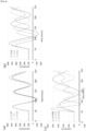
FIG. 7 is a graph of current waveforms showing the analysis results of current fluctuations in the direct-current limiter according to the embodiment of the present invention, in whichFIG. 7(a) shows a case where the resistance value R of the first inductor is changed, andFIG. 7(b) shows a case where the resistance value R of the second inductor is changed. - Hereinafter, an embodiment of the present invention will be described based on the drawings.
-
FIGS. 1 to 7 show a direct-current limiter and a direct-current circuit breaker system according to an embodiment of the present invention. - As shown in
FIG. 1 , a direct-currentcircuit breaker system 10 is a direct-current circuit breaker system for interrupting a direct current flowing through a direct-current line 1, and includes a direct-current limiter 11 and aninterrupting unit 12. - The direct-
current limiter 11 includes an LCparallel circuit 11a including afirst inductor 21 and acapacitor 22, and asecond inductor 23. The LCparallel circuit 11a is inserted into the direct-current line 1, and thefirst inductor 21 and thecapacitor 22 are connected in parallel to each other. Thesecond inductor 23 is inserted into the direct-current line 1 and connected in series to the LCparallel circuit 11a. Thesecond inductor 23 may be connected to the upstream side or the downstream side of the direct current flowing through the direct-current line 1 with respect to the LCparallel circuit 11a. It is preferable that thefirst inductor 21 has a larger inductance than thesecond inductor 23. Thefirst inductor 21 and thesecond inductor 23 preferably have a smaller resistance value to direct current, and are particularly preferably made of superconducting coils. - The interrupting
unit 12 is inserted in the direct-current line 1. The interruptingunit 12 is connected on the downstream side of the direct current flowing through the direct-current line 1 with respect to the LCparallel circuit 11a and thesecond inductor 23. The interruptingunit 12 is configured to interrupt the current flowing through the direct-current line 1 when the passing current that has passed through the LCparallel circuit 11a and thesecond inductor 23 satisfies a predetermined condition. The interruptingunit 12 may be any type capable of interrupting the direct-current line 1, but is preferably made of a type capable of effectively interrupting a changing current. - The direct-
current limiter 11 and the direct-currentcircuit breaker system 10 operate according to the following principle. First, as shown inFIG. 2(a) , a constant direct current flows through the direct-current line 1 in a normal state. At this time, in the LCparallel circuit 11a, since no current flows through thecapacitor 22, a current flows only through thefirst inductor 21. A current also flows through thesecond inductor 23 connected in series to the LCparallel circuit 11a. Here, by reducing the resistance value of thefirst inductor 21 and thesecond inductor 23 to the direct current, it is possible to suppress the voltage generation in the LCparallel circuit 11a and thesecond inductor 23 in the normal state and reduce power loss. In particular, when both thefirst inductor 21 and thesecond inductor 23 are made of superconducting coils, it is possible to make the resistance value to the direct current almost zero, and to make power loss almost zero. Also, even if either thefirst inductor 21 or thesecond inductor 23 is a superconducting coil, it is possible to suppress power loss. - Next, as shown in
FIG. 2(b) , when an accident such as a short circuit occurs, the current flowing through the direct-current line 1 changes. At this time, in the LCparallel circuit 11a, since thecapacitor 22 has a smaller resistance to the alternating current than thefirst inductor 21, a current starts to flow through thecapacitor 22. In addition, a voltage is generated in thesecond inductor 23 along with the change in current. As a result, a transient phenomenon occurs between thecapacitor 22 and thesecond inductor 23 of the LCparallel circuit 11a, and the current value flowing through the direct-current line 1 increases and decreases. Therefore, even if the current value temporarily increases due to an accident, the current value can be reduced by the transient phenomenon, and the current can be reliably limited. In particular, when thefirst inductor 21 and thesecond inductor 23 are made of superconducting coils, the amplitude of the increase and decrease in the current value due to the transient phenomenon occurring at the time of the accident can be increased, and the minimum value of the current (current at the time of current limiting) can be reduced. - When an accident such as a short circuit occurs, the current can be reliably interrupted by configuring the interrupting
unit 12 so that the current is interrupted, for example, when any of the following conditions are met. - <
Condition 1> When the passing current becomes equal to or less than a predetermined current value (for example, zero amperes). - <
Condition 2> When the passing current fluctuates by a predetermined value or more from the current value of the direct current before the fluctuation. - <
Condition 3> When the passing current repeatedly increases and decreases with a predetermined amplitude or more. - In the case of
condition 1, the current can be interrupted when the passing current is limited. In particular, by interrupting the current when the passing current becomes zero amperes, it is possible to prevent arc discharge from occurring when the current is interrupted. By preventing arc discharge, it is possible to prevent wear on the contacts and arc chutes, noise during interruption, and damage to peripheral devices. In addition, since it is not necessary to secure an arc space, it is possible to reduce the size of the interruptingunit 12. In this case, an alternating-current circuit breaker can be used as the interruptingunit 12. In the case ofcondition 2, it is possible to detect the occurrence of an accident due to fluctuations in the passing current and interrupt the current. In the case ofcondition 3, it is possible to detect the occurrence of an accident due to the occurrence of a transient phenomenon and interrupt the current. - In this way, the direct-current
circuit breaker system 10 can reliably interrupt the current by the interruptingunit 12 interrupting the current flowing through the direct-current line 1 when the passing current that has passed through the LCparallel circuit 11a and thesecond inductor 23 satisfies the predetermined conditions such asconditions 1 to 3. Therefore, even in the case of an accident where the current rises quickly, the direct-current line 1 can be interrupted by limiting the current more reliably. The direct-currentcircuit breaker system 10 can prevent an interruption failure because the direct-current limiter 11 can suppress the maximum current Imax in the event of an accident and can ensure a time margin until the current is interrupted. - The operation of the direct-
current limiter 11 and the direct-currentcircuit breaker system 10 was analyzed using commercially available analysis software "MATLAB®/Simulink (manufactured by MathWorks, Inc.)". The circuit used for the analysis is shown inFIG. 3 . The circuit inFIG. 3 is a circuit in which avariable resistor 2 is inserted in the direct-current line 1 of the circuit shown inFIG. 1 to represent the load of the power supply destination in a normal state and the load in the event of an accident such as a short circuit. - First, an analysis of the interruption operation was performed using current waveform data simulating a ground fault accident as accident data. The current waveform data used is shown in
FIG. 4 . In the data shown inFIG. 4 , the rate of change of current over time dI/dt is constant at 80 kA/sec, and the current rises from a steady current of 100 A to 16000 A 200 msec after the occurrence of the accident. It was also assumed that the current would rise until the analysis was completed if the current was not interrupted. In the analysis, the data shown inFIG. 4 was input to thevariable resistor 2. The voltage E of thepower supply 3 was set to 1500 V, the inductance L1 of thefirst inductor 21 to 1 H, the capacitance C of thecapacitor 22 to 4.5 mF, and the inductance L2 of thesecond inductor 23 to 0.03 H. In the analysis, the current was interrupted by the interruptingunit 12 when the passing current that has passed through the interruptingunit 12 became zero amperes. The resistance of the interruptingunit 12 was 0.001 Ω, and the conductance was 10-6 S. -
FIG. 5 shows the analyzed current waveform at the time of the accident. Note thatFIG. 5 also shows the case where there is no interrupting unit 12 (where the current is not interrupted). As shown inFIG. 5 , it was confirmed that the current value temporarily increases due to the short circuit accident, but the current decreases due to the transient phenomenon, and the current was reliably limited. It was also confirmed that the current was interrupted by the interruptingunit 12 the moment the passing current became zero amperes. Specifically, it was confirmed that the maximum current Imax was suppressed to 480 A. It was also confirmed that the current was interrupted within 100 msec (about 50 msec) after the accident occurred. Note that from the graph for the case where there is no interruptingunit 12, it was confirmed that the current value oscillates with the maximum current Imax suppressed due to the transient phenomenon. From this, it can be said that a time margin until interruption can be secured. - Next, the parameters of the inductance L1 of the
first inductor 21, the capacitance C of thecapacitor 22, and the inductance L2 of thesecond inductor 23 in the circuit were changed to analyze the current fluctuation. In the analysis, the data shown inFIG. 4 was used as the accident waveform data to be input to thevariable resistor 2. In addition, the voltage E of thepower supply 3 was set to 1500 V, and the interruptingunit 12 was not provided. Analysis was performed for three cases: a case where the inductance L1 of thefirst inductor 21 was changed, a case where the capacitance C of thecapacitor 22 was changed, and a case where the inductance L2 of thesecond inductor 23 was changed. The values of the parameters used in the analysis for these three cases are shown in Table 1.[Table 1] Case where L1 is changed Case where C is changed Case where L2 is changed L1 [H] C [mF] L2 [H] L1 [H] C [mF] L2 [H] L1 [H] C [mF] L2 [H] 0.8 4.5 0.03 1 3 0.03 1 4.5 0.09 1 4.5 0.03 1 5 0.03 1 4.5 0.05 1.2 4.5 0.03 1 7 0.03 1 4.5 0.01 - The current waveforms after the accident for the three cases shown in Table 1 are shown in
FIG. 6(a) to 6(c) , respectively. As shown inFIG. 6(a) , it was confirmed that the amplitude of the current due to the transient phenomenon becomes smaller as the inductance L1 of thefirst inductor 21 increases. It was also confirmed that the period of the current due to the transient phenomenon does not change even if the inductance L1 changes. As shown inFIG. 6(b) , it was confirmed that the amplitude of the current due to the transient phenomenon becomes larger and the period becomes longer as the capacitance C of thecapacitor 22 increases. As shown inFIG. 6(c) , it was confirmed that the initial amplitude of the current due to the transient phenomenon becomes smaller and the period becomes longer as the inductance L2 of thesecond inductor 23 increases. - In addition, in all cases shown in
FIGS. 6(a) to 6(c) , it was confirmed that the minimum value of the current due to the transient phenomenon is zero amperes or less, but the minimum value changes depending on the value of each parameter. Therefore, for example, in order to interrupt the current when the current becomes zero amperes so that arc discharge during interruption is prevented, it is necessary to adjust the value of each parameter taking into account the value of the constant current in the normal state. - Next, an analysis of current fluctuations was performed in a case where the
first inductor 21 or thesecond inductor 23 in the circuit has a resistance. In the analysis, the data shown inFIG. 4 was used as the accident data to be input to thevariable resistor 2. In addition, the voltage E of thepower supply 3 was set to 1500 V, the inductance L1 of thefirst inductor 21 to 1H, the capacitance C of thecapacitor 22 to 4.5 mF, and the inductance L2 of thesecond inductor 23 to 0.03 H. In addition, the interruptingunit 12 was not provided. Analysis was performed for a case where the resistance value R of thefirst inductor 21 was changed in the range of 0 S2 to 40 S2 (the resistance value of thesecond inductor 23 was 0 S2) and for a case where the resistance value R of thesecond inductor 23 was changed in the range of 0 S2 to 10 S2 (the resistance value of thefirst inductor 21 was 0 S2). - The current waveforms after the accident in each case are shown in
FIGS. 7(a) and 7(b) , respectively. As shown inFIG. 7(a) , it was confirmed that the value of the constant current in the normal state becomes smaller and the amplitude of the current due to the transient phenomenon also becomes smaller as the resistance value of thefirst inductor 21 increases. Similarly, as shown inFIG. 7(b) , it was confirmed that the value of the constant current in the normal state becomes smaller and the amplitude of the current due to the transient phenomenon also becomes smaller as the resistance value of thesecond inductor 23 increases. It was also confirmed that the resistance of thesecond inductor 23 has a greater effect on the amplitude of the current due to the transient phenomenon than the resistance of thefirst inductor 21. - From these results, it was confirmed that in order to reduce power loss in the normal state, it is necessary to reduce the resistance values of the
first inductor 21 and thesecond inductor 23. In particular, it can be said that in order to reduce power loss to almost zero, it is necessary to use superconducting coils as thefirst inductor 21 and thesecond inductor 23. It was also confirmed that by using superconducting coils for thefirst inductor 21 and thesecond inductor 23, it is possible to increase the amplitude of the increase and decrease in the current value due to the transient phenomenon that occurs in the event of an accident, reduce the minimum value of the current (current at the time of current limiting), and make it easier to reduce the current to zero amperes or less. As a result, it can be said that it is possible to configure so that the current is interrupted when it becomes zero amperes, and it is possible to prevent the occurrence of arc discharge and make it easier to interrupt the current. In addition, by using superconducting coils, it is possible to increase the inductance while the resistance value is almost zero, and therefore it can be said that it is possible to reduce the size and weight of thefirst inductor 21, which has a particularly large inductance. -
- 1
- Direct-current line
- 2
- Variable resistor
- 3
- Power supply
- 10
- Direct-current circuit breaker system
- 11
- Direct-current limiter
- 11a
- LC parallel circuit
- 21
- First inductor
- 22
- Capacitor
- 23
- Second capacitor
- 12
- Interrupting unit
Claims (7)
- A direct-current limiter for limiting a direct current in order to interrupt the direct current flowing through a direct-current line, comprising:an LC parallel circuit having a first inductor and a capacitor connected in parallel to each other; anda second inductor inserted in the direct-current line and connected in series to the LC parallel circuit.
- The direct-current limiter according to claim 1, wherein at least one of the first inductor and the second inductor is made of superconducting coils.
- A direct-current circuit breaker system comprising:the direct-current limiter according to claim 1 or 2; andan interrupting unit configured to interrupt the current flowing through the direct-current line when a passing current that has passed through the LC parallel circuit and the second inductor satisfies a predetermined condition.
- The direct-current circuit breaker system according to claim 3, wherein the interrupting unit is configured to interrupt the current flowing through the direct-current line when the passing current becomes equal to or less than a predetermined current value.
- The direct-current circuit breaker system according to claim 3, wherein the interrupting unit is configured to interrupt the current flowing through the direct-current line when the passing current becomes zero amperes.
- The direct-current circuit breaker system according to claim 3, wherein the interrupting unit is configured to interrupt the current flowing through the direct-current line when the passing current varies by a predetermined value or more from a current value of the direct current.
- The direct-current circuit breaker system according to claim 3, wherein the interrupting unit is configured to interrupt the current flowing through the direct-current line when the passing current repeatedly increases and decreases with a predetermined amplitude or more.
Applications Claiming Priority (1)
| Application Number | Priority Date | Filing Date | Title |
|---|---|---|---|
| PCT/JP2022/002669 WO2023144885A1 (en) | 2022-01-25 | 2022-01-25 | Direct-current limiter and direct-current interruption system |
Publications (2)
| Publication Number | Publication Date |
|---|---|
| EP4471819A1 true EP4471819A1 (en) | 2024-12-04 |
| EP4471819A4 EP4471819A4 (en) | 2025-03-05 |
Family
ID=87471141
Family Applications (1)
| Application Number | Title | Priority Date | Filing Date |
|---|---|---|---|
| EP22923754.0A Pending EP4471819A4 (en) | 2022-01-25 | 2022-01-25 | DC LIMITER AND DC INTERRUPTION SYSTEM |
Country Status (3)
| Country | Link |
|---|---|
| EP (1) | EP4471819A4 (en) |
| JP (1) | JPWO2023144885A1 (en) |
| WO (1) | WO2023144885A1 (en) |
Family Cites Families (6)
| Publication number | Priority date | Publication date | Assignee | Title |
|---|---|---|---|---|
| US4805062A (en) * | 1986-10-15 | 1989-02-14 | Hitachi, Ltd. | DC circuit breaker and method of commutation thereof |
| JP3965037B2 (en) * | 2001-10-12 | 2007-08-22 | 東芝三菱電機産業システム株式会社 | DC vacuum interrupter |
| EP2495745A1 (en) * | 2011-03-04 | 2012-09-05 | ABB Technology AG | Current-rise limitation in high-voltage DC systems |
| FR3030105B1 (en) * | 2014-12-11 | 2017-05-26 | Inst Supergrid | HIGH VOLTAGE CONTINUOUS CURRENT CUTTING DEVICE |
| CN110912083B (en) * | 2019-11-29 | 2021-10-12 | 天津大学 | Direct current source based on magnetic coupling enhancement characteristic current limiter and control method thereof |
| CN111817274A (en) * | 2020-07-18 | 2020-10-23 | 西安交通大学 | Gas DC circuit breaker and working method by means of voltage charging method of current limiting device |
-
2022
- 2022-01-25 WO PCT/JP2022/002669 patent/WO2023144885A1/en not_active Ceased
- 2022-01-25 EP EP22923754.0A patent/EP4471819A4/en active Pending
- 2022-01-25 JP JP2023576285A patent/JPWO2023144885A1/ja active Pending
Also Published As
| Publication number | Publication date |
|---|---|
| EP4471819A4 (en) | 2025-03-05 |
| JPWO2023144885A1 (en) | 2023-08-03 |
| WO2023144885A1 (en) | 2023-08-03 |
Similar Documents
| Publication | Publication Date | Title |
|---|---|---|
| US10756536B2 (en) | System for handling short circuits on an electrical network | |
| US10541622B2 (en) | Electric motor drive device | |
| EP2777059B1 (en) | Hybrid dc circuit breaking device | |
| CA2713369C (en) | Power rectifying circuit and systems, associated method, and aircraft including such circuit or systems | |
| EP3736964B1 (en) | Method for controlling shutdown wave blocking of multilevel inverter circuit and application apparatus thereof | |
| JP4447655B1 (en) | Magnetic energy regenerative switch with protection circuit | |
| EP3262731B1 (en) | Robust solid-state circuit protection apparatus | |
| EP2894653B1 (en) | Dc breaker | |
| CN112366669A (en) | Optimal configuration method and device for current-limiting reactor in multi-terminal direct-current power transmission system | |
| JP6069073B2 (en) | Current limiting device | |
| EP2549609A2 (en) | Protection coordination system with current limiter | |
| WO2025066271A1 (en) | Forced current-sharing circuit, chip, motherboard, and electronic device | |
| US11972915B2 (en) | Breaking device | |
| EP4503362A2 (en) | Surge protection and failsafe circuit for dc-dc converter | |
| EP4287481A1 (en) | Low voltage buck regulator voltage regulation with reduced overshoot and settling time | |
| Naghibi et al. | Interline bridge‐type fault current limiter: a novel approach for limiting fault current in distribution network | |
| WO2023144885A1 (en) | Direct-current limiter and direct-current interruption system | |
| JP4120618B2 (en) | DC feeding network protection system | |
| Milanov | Overvoltage Protection of Sensitive Consumers in DC-Powered Industrial Rail Grid | |
| KR101361085B1 (en) | Apparatus and Method for controlling abnormal current | |
| JP5197542B2 (en) | Superconducting current limiting system | |
| KR102427627B1 (en) | Inrush current limit circuit arrangement structure in a system having a plurality of load equipment and the systems having the arrangement structure | |
| JPH08331756A (en) | Inrush current prevention device and electronic circuit protection device | |
| KR102264598B1 (en) | Flux-Coupling type superconducting fault current limiter with two triggered current limiting levels | |
| EP0107359A2 (en) | Alternating current limiting type semiconductor current circuit breaker |
Legal Events
| Date | Code | Title | Description |
|---|---|---|---|
| STAA | Information on the status of an ep patent application or granted ep patent |
Free format text: STATUS: THE INTERNATIONAL PUBLICATION HAS BEEN MADE |
|
| PUAI | Public reference made under article 153(3) epc to a published international application that has entered the european phase |
Free format text: ORIGINAL CODE: 0009012 |
|
| STAA | Information on the status of an ep patent application or granted ep patent |
Free format text: STATUS: REQUEST FOR EXAMINATION WAS MADE |
|
| 17P | Request for examination filed |
Effective date: 20240822 |
|
| AK | Designated contracting states |
Kind code of ref document: A1 Designated state(s): AL AT BE BG CH CY CZ DE DK EE ES FI FR GB GR HR HU IE IS IT LI LT LU LV MC MK MT NL NO PL PT RO RS SE SI SK SM TR |
|
| A4 | Supplementary search report drawn up and despatched |
Effective date: 20250204 |
|
| RIC1 | Information provided on ipc code assigned before grant |
Ipc: H02H 9/02 20060101ALN20250129BHEP Ipc: H02H 3/02 20060101ALN20250129BHEP Ipc: H01F 6/00 20060101ALN20250129BHEP Ipc: H02H 7/00 20060101ALI20250129BHEP Ipc: H02H 3/087 20060101ALI20250129BHEP Ipc: H01H 33/59 20060101AFI20250129BHEP |
|
| DAV | Request for validation of the european patent (deleted) | ||
| DAX | Request for extension of the european patent (deleted) |