EP4471773A1 - Sense amplifier circuit, corresponding memory device and method of operation - Google Patents
Sense amplifier circuit, corresponding memory device and method of operation Download PDFInfo
- Publication number
- EP4471773A1 EP4471773A1 EP24167364.9A EP24167364A EP4471773A1 EP 4471773 A1 EP4471773 A1 EP 4471773A1 EP 24167364 A EP24167364 A EP 24167364A EP 4471773 A1 EP4471773 A1 EP 4471773A1
- Authority
- EP
- European Patent Office
- Prior art keywords
- node
- bit line
- supply voltage
- activation signal
- ymps
- Prior art date
- Legal status (The legal status is an assumption and is not a legal conclusion. Google has not performed a legal analysis and makes no representation as to the accuracy of the status listed.)
- Granted
Links
Images




Classifications
-
- G—PHYSICS
- G11—INFORMATION STORAGE
- G11C—STATIC STORES
- G11C7/00—Arrangements for writing information into, or reading information out from, a digital store
- G11C7/06—Sense amplifiers; Associated circuits, e.g. timing or triggering circuits
- G11C7/065—Differential amplifiers of latching type
-
- G—PHYSICS
- G11—INFORMATION STORAGE
- G11C—STATIC STORES
- G11C13/00—Digital stores characterised by the use of storage elements not covered by groups G11C11/00, G11C23/00, or G11C25/00
- G11C13/0002—Digital stores characterised by the use of storage elements not covered by groups G11C11/00, G11C23/00, or G11C25/00 using resistive RAM [RRAM] elements
- G11C13/0021—Auxiliary circuits
- G11C13/004—Reading or sensing circuits or methods
-
- G—PHYSICS
- G11—INFORMATION STORAGE
- G11C—STATIC STORES
- G11C13/00—Digital stores characterised by the use of storage elements not covered by groups G11C11/00, G11C23/00, or G11C25/00
- G11C13/0002—Digital stores characterised by the use of storage elements not covered by groups G11C11/00, G11C23/00, or G11C25/00 using resistive RAM [RRAM] elements
- G11C13/0004—Digital stores characterised by the use of storage elements not covered by groups G11C11/00, G11C23/00, or G11C25/00 using resistive RAM [RRAM] elements comprising amorphous/crystalline phase transition cells
-
- G—PHYSICS
- G11—INFORMATION STORAGE
- G11C—STATIC STORES
- G11C13/00—Digital stores characterised by the use of storage elements not covered by groups G11C11/00, G11C23/00, or G11C25/00
- G11C13/0002—Digital stores characterised by the use of storage elements not covered by groups G11C11/00, G11C23/00, or G11C25/00 using resistive RAM [RRAM] elements
- G11C13/0021—Auxiliary circuits
- G11C13/0023—Address circuits or decoders
- G11C13/0026—Bit-line or column circuits
-
- G—PHYSICS
- G11—INFORMATION STORAGE
- G11C—STATIC STORES
- G11C13/00—Digital stores characterised by the use of storage elements not covered by groups G11C11/00, G11C23/00, or G11C25/00
- G11C13/0002—Digital stores characterised by the use of storage elements not covered by groups G11C11/00, G11C23/00, or G11C25/00 using resistive RAM [RRAM] elements
- G11C13/0021—Auxiliary circuits
- G11C13/0038—Power supply circuits
Definitions
- the description relates to circuits and methods for biasing the bit lines of a memory device via a sense amplifier circuit.
- Such sense amplifiers may be used, for instance, during read operation from nonvolatile memories (NVM) such as embedded phase-change memories (embedded PCM, ePCM).
- NVM nonvolatile memories
- embedded PCM embedded PCM
- Such memories may be applied, for instance, to general-purpose microcontrollers (GP MCU) and secure microcontrollers.
- Read operations e.g., fetching of data
- phase-change memories are used to output (e.g., fetch, extract) the content of PCM data words on an output data bus (e.g., a 145-bit bus DATA_OUT[144:0]).
- an output data bus e.g., a 145-bit bus DATA_OUT[144:0]
- Figure 1 is a (simplified) circuit diagram exemplary of a reading architecture in a PCM memory
- Figure 2 is a time diagram including waveforms of signals during a read operation in the architecture of Figure 1
- a memory 10 includes an array of memory cells 102 (e.g., phase-change memory cells) arranged in bit lines 103B (here illustrated as vertical lines) and word lines 103W 1 , 103W 2 , 103W 3 (here illustrated as horizontal lines, also collectively or individually referred to as word lines 103W) according to a memory architecture known per se.
- memory cells 102 e.g., phase-change memory cells
- bit lines 103B here illustrated as vertical lines
- word lines 103W 1 , 103W 2 , 103W 3 here illustrated as horizontal lines, also collectively or individually referred to as word lines 103W
- each memory cell 102 may be arranged in series to a respective selection transistor 104 (e.g., a pnp BJT transistor) between a ground voltage terminal and the respective bit line 103B.
- the selection transistors 104 of the same word line 103W receive the same control signal at their control (e.g., base) terminals, e.g., control signals WL1, WL2, WL3 as exemplified in Figures 1 and 2 .
- Each bit line 103B may be selectively coupled (e.g., via a respective p-channel MOS transistor 106 having its current path in series to the bit line and receiving a control signal Y_SEL ) to a memory supply voltage rail 108 that provides a regulated voltage V REG (e.g., having a target value V BL_CHARGE ).
- respective clamping transistors 110 e.g., pnp BJT transistors
- the clamping transistors 110 may receive the same control signal WL CLAMP at their control (e.g., base) terminals.
- Each bit line 103B has a respective capacitive load C BL due to the capacitances of the memory cells 102 and/or of the transistors 106, 110.
- a read operation in a phase-change memory as exemplified in Figure 1 may be carried out as exemplified in Figure 2 to read (and provide as output) the content of plural PCM words on an output data bus DATA_OUT[144:0],
- information may be stored associating two cells to each bit: a SET cell (having low resistance and high current) and a RESET cell (having high resistance and low current).
- a memory sense circuit may read information from the cells in differential mode.
- T ACC the specification for the memory access time
- T ACC the specification for the memory access time
- read parallelism e.g., reading two words in parallel
- sensing of the content of the memory cells may be carried out in differential mode: a sensing circuit reads in differential mode from the bit line BL_SET and the bit line BL_RESET, so that the SET memory cell and the RESET memory cell are selected.
- the SET memory cell and the RESET memory cell are selected by properly driving the control signals (word selection signals) WL1, WL2, WL3: for instance, as exemplified in Figure 2 , by keeping signals WL1 and WL3 at a high logic value (e.g., equal to value V BL_CHARGE ) and by driving signal WL2 to a low logic value (e.g., equal to the ground voltage, 0 V), cell 102 S is selected as the SET cell and cell 102 R is selected as the RESET cell.
- word selection signals word selection signals
- WL1, WL2, WL3 for instance, as exemplified in Figure 2 , by keeping signals WL1 and WL3 at a high logic value (e.g., equal to value V BL_CHARGE ) and by driving signal WL2 to a low logic value (e.g., equal to the ground voltage, 0 V)
- cell 102 S is selected as the SET cell
- cell 102 R is selected as the RESET
- a voltage regulator (e.g., a low-dropout, LDO, regulator) produces the regulated voltage V REG at the supply rail 108 (e.g., having a target voltage value V BL_CHARGE ).
- the value V BL_CHARGE of voltage V REG should be high enough to provide a proper voltage stack to the bit lines to result in the correct values of the memory cells currents.
- the voltage V BL at the selected bit lines is clamped to the value V BE of the base-emitter voltage of the clamping transistors 110, and then the bit lines are pre-charged to the value V BL_CHARGE by the regulated voltage V REG by activating the transistors 106 (see in Figure 2 the control signal WL CLAMP switching from a low value to a high value V BL_CHARGE to switch off transistors 110 and the control signal Y_SEL switching from a high value V BL_CHARGE to a low value to switch on transistors 106).
- the control signals WL1 and WL3 of the unselected word lines are kept at a high voltage value (e.g., V BL_CHARGE ) so as to keep the respective selection transistors in a nonconductive state.
- Embedded phase-change memories with BJT selectors as exemplified herein may thus rely on the bit lines being biased (e.g., pre-charged) to a target voltage level V BL_CHARGE at each read operation.
- the current required for pre-charging the bit lines i.e., pre-charge the capacitances C BL
- the LDO regulator provides the current directly from the supply rail Vcc to prevent high current consumption.
- the value of the target voltage V BL_CHARGE may be approximately equal to 1.76 V, that is, higher than the minimum supply voltage V CCMIN that may be approximately equal to 1.62 V, for different reasons (e.g., to increase the SET-RESET distance in order to enlarge the reading window for improving the reliability margins, and/or to increase the reading margin versus noise and speed requirements).
- the LDO regulator may be unable to satisfy such a requirement, and a charge pump (CP) may be integrated in the LDO regulator to provide a boosted voltage (i.e., higher than V CCMIN ).
- CP charge pump
- activation of the charge pump may result in a relevant increase of the current consumption. For instance, current consumption during read operations may be almost doubled when the charge pump is activated.
- An object of one or more embodiments is to contribute in providing such improved sense amplifiers for phase-change memories.
- such an object can be achieved by a sense amplifier circuit having the features set forth in the claims that follow.
- One or more embodiments may relate to a corresponding memory device.
- One or more embodiments may relate to a corresponding method of operation (e.g., a memory reading method).
- a sense amplifier circuit for a memory device includes a first input terminal and a second input terminal configured for coupling to a first memory sensing node and a second memory sensing node, respectively.
- a sensing circuit is coupled to the first and second input terminals and is configured to sense a differential signal therebetween.
- a first boosting capacitor has a first terminal coupled to the first input terminal and a second terminal coupled to a floating node.
- a second boosting capacitor has a first terminal coupled to the second input terminal and a second terminal coupled to the floating node.
- a control circuitry is configured to receive a bit line boosting activation signal.
- the first terminals of the first and second boosting capacitors are coupled to a regulated supply node that provides a regulated supply voltage and the floating node is driven to a ground voltage.
- the first terminals of the first and second boosting capacitors are decoupled from the regulated supply node and the floating node is driven to the regulated supply voltage.
- One or more embodiments may thus provide a sense amplifier circuit that facilitates boosting the pre-charge voltage of the bit lines, without resorting to a charge pump circuit integrated in the voltage regulator that supplies the memory device.
- a memory device includes a plurality of memory banks. Each memory bank is coupled to a respective sense amplifier circuit according to one or more embodiments. Each memory bank includes an array of memory cells arranged in a plurality of bit lines and a plurality of word lines. Each memory cell is arranged in series to a respective selection transistor between a ground terminal and the corresponding bit line, and each bit line is selectively couplable to a regulated supply node that provides a regulated supply voltage, or to one of the first and second memory sensing nodes.
- a voltage detector circuit is configured to sense a system supply voltage and to detect whether the system supply voltage is higher than a threshold (e.g., a target bit line pre-charge voltage).
- a voltage regulator circuit is coupled to the system supply voltage and is configured to produce the regulated supply voltage at the regulated supply node.
- the voltage detector circuit is further configured to set an LDO activation signal to a first value and disable the bit line boosting activation signal in response to the system supply voltage being higher than the threshold.
- the voltage detector circuit is further configured to set the LDO activation signal to a second value and enable the bit line boosting activation signal in response to the system supply voltage being lower than or equal to the threshold.
- the voltage detector circuit is further configured to set the bit line boosting activation signal to the first value as long as the bit lines are coupled to the regulated supply node.
- the voltage detector circuit is further configured to set the bit line boosting activation signal to the second value in response to a pair of selected bit lines being coupled to the first and second memory sensing nodes, respectively.
- the voltage regulator circuit is configured to regulate the regulated supply voltage to a value equal to the threshold in response to the LDO activation signal having the first value, and regulate the regulated supply voltage to a value as close as possible to the system supply voltage in response to the LDO activation signal having the second value.
- a method of operating a memory device includes:
- references to "an embodiment” or “one embodiment” in the framework of the present description is intended to indicate that a particular configuration, structure, or characteristic described in relation to the embodiment is included in at least one embodiment.
- phrases such as “in an embodiment” or “in one embodiment” that may be present in one or more points of the present description do not necessarily refer to one and the same embodiment.
- particular configurations, structures, or characteristics may be combined in any adequate way in one or more embodiments.
- Figure 3 is a circuit diagram exemplary of a reading architecture of a PCM memory bank 10B. It will be noted that for ease of illustration, a single word line 103W is visible in Figure 3 , and plural bit lines 103B. It will also be noted that certain elements of the array of the memory bank 10B are illustrated only once for ease of illustration as well.
- the bit lines are arranged in two main groups (e.g., a left group and a right group), with the two main groups including the same number of bit lines (e.g., 16 bit lines), in order to allow differential reading.
- a differential voltage is sensed between two bit lines (a SET line and a RESET line), one belonging to the left group and the other belonging to the right group.
- the two main groups are each subdivided in a number n of subgroups or "main bit lines" 103BM, e.g., 2 subgroups, each subgroup including a number m of bit lines, e.g., 8 bit lines.
- Each main bit line has an associated parasitic capacitance C MAIN (e.g., C MAIN,L for the main bit lines in the left group and C MAIN,R for the main bit lines in the right group).
- Each common node 300 (e.g., each main bit line) is selectively couplable via respective switches either to the supply voltage rail 108 at voltage V REG or to a respective sensing node 302 (e.g., a left sensing node 302 L for the main bit lines of the left group and a right sensing node 302 R for the main bit lines of the right group).
- a respective sensing node 302 e.g., a left sensing node 302 L for the main bit lines of the left group and a right sensing node 302 R for the main bit lines of the right group.
- a first main bit line in the left group and a first main bit line in the right group can be coupled to rail 108 depending on the value of signal NYN ⁇ i>
- the sense amplifier core 30 (e.g., a latch-type sense amplifier) includes differential input nodes 304 L and 304 R .
- Node 304 L is selectively couplable to node 302 L via a switch SW YMPS,L
- node 304 R is selectively couplable to node 302 R via a switch SW YMPS,R .
- switches SW YMPS,L and SW YMPS,R are configured to isolate nodes 304 L and 304 R from nodes 302 L and 302 R since the latter nodes may assume high voltage values during write operations.
- Nodes 304 L and 304 L are selectively couplable to each other via a switch SW CONNECT .
- a first input capacitor C INL of the sense amplifier 30 has a first terminal coupled to node 304 L and a second terminal coupled to a node 306 L
- a second input capacitor C INR of the sense amplifier 30 has a first terminal coupled to node 304 R and a second terminal coupled to a node 306 R .
- the sense amplifier core 30 further includes: a first inverter INV1 having an input terminal coupled to node 306 L and an output terminal coupled to a node 308 R , a first capacitor C R coupled between nodes 308 R and 306 R , a first switch SW1 that bypasses inverter INV1 (e.g., coupled between the input and output terminals of inverter INV1), a second inverter INV2 having an input terminal coupled to node 306 R and an output terminal coupled to a node 308 L , a second capacitor C L coupled between nodes 308 L and 306 L , and a second switch SW2 that bypasses inverter INV2 (e.g., coupled between the input and output terminals of inverter INV2).
- a first inverter INV1 having an input terminal coupled to node 306 L and an output terminal coupled to a node 308 R
- a first capacitor C R coupled between nodes 308 R and 306 R
- Inverters INV1 and INV2 are enabled by an enable signal EN_SA, and are supplied at a voltage V DD normally lower than the regulated voltage V REG (not visible in Figure 3 for ease of illustration). Switches SW1 and SW2 may be controlled by the same equalization signal EQ (not visible in Figure 3 for ease of illustration).
- Read operation in a memory bank 10B as exemplified in Figure 3 may be carried out according to the procedure described in the following.
- the main bit lines (e.g., all nodes 300 L and 300 R ) are connected to the supply voltage rail 108 and charged by voltage V REG to the target value V BL_CHARGE (e.g., about 1.7 V).
- the word line signal WL applied to the word line 103W is also driven to the value V BL_CHARGE .
- signals YN ⁇ i>, YN ⁇ i+1>, ... are set so as to connect one of nodes 300 L of the left group and the corresponding (e.g., homologous, symmetrical) node 300 R of the right group to the sensing nodes 302 L and 302 R , respectively, thereby selecting the main bit lines for reading.
- sensing node 302 L is connected to the input node 304 L of the sense amplifier core 30 by closing switch SW YMPS,L
- sensing node 302 R is connected to the input node 304 R of the sense amplifier core 30 by closing switch SW YMPS,R .
- the remaining switches are open during the first step, that is: all nodes 300 that do not correspond to a selected main bit line are decoupled from the respective sensing node 302, all the bit lines are decoupled from the respective node 300 (at this stage), and switches SW CONNECT , SW1 and SW2 of the sense amplifier core 30 are open as well.
- the enable signal EN_SA is set at a value that switches off the inverters INV1 and INV2, i.e., it is de-asserted (e.g., set to a low logic value, ground voltage, 0 V).
- switches SW1 and SW2 are closed (e.g., equalization signal EQ is asserted) and enable signal EN_SA is asserted (e.g., set to a high logic value) so as to activate inverters INV1 and INV2.
- enable signal EN_SA is asserted (e.g., set to a high logic value) so as to activate inverters INV1 and INV2.
- input offset of the sense amplifier core 30 is compensated and the input capacitors C INL , C INR are pre-charged.
- a selected bit line pertaining to the left group and to the selected main bit line i.e., the left main bit line that is currently connected to node 302 L
- the corresponding main bit line e.g., node 300 L
- the corresponding selected bit line pertaining to the right group and to the selected main bit line i.e., the right main bit line that is currently connected to node 302 R
- the selected bit lines are pre-charged, i.e., the respective capacitances C BL are charged from voltage V BE (e.g., about 0.6 V) to the target voltage V BL_CHARGE .
- the selected main bit lines (left and right) are disconnected from the supply voltage rail 108 by opening the respective switches controlled by signals NYN ⁇ i>.
- the word line signal WL applied to a certain word line 103W is driven to ground voltage, thereby activating the selection transistors 104 and carrying out the actual word line selection (i.e., selection of two specific memory cells 102 L and 102 R ).
- capacitive nodes 300 L and 300 R e.g., the bit line capacitances C BL and the main bit line capacitances C MAIN ) start discharging and the voltage at nodes 300 L and 300 R (that are connected to the sensing nodes 302 L and 302 R ) drops during a so-called "discharge window".
- capacitor C INL is charged to a certain voltage V LEFT and capacitor C INR is charged to a certain voltage V RIGHT depending on the resistance of the memory cells 102 L and 102 R .
- switches SW YMPS,L and SW YMPS,R are opened to disconnect the sense amplifier core 30 (whose input terminals have been charged) from the memory array.
- Switches SW1 and SW2 are opened as well, and switch SW CONNECT is closed. In this state, sensing of the differential voltage (e.g., difference between V LEFT and V RIGHT ) is carried out by the sense amplifier core 30.
- Biasing architecture 40 includes a voltage detector 42, an LDO regulator 44, and a charge pump circuit 46, all biased by the memory supply voltage Vcc.
- the voltage detector 42 is configured to sense the voltage V REG at node 108 and the voltage Vcc, and is configured to determine whether the supply voltage Vcc is higher or lower than the expected (e.g., target or required) bit line voltage V BL_CHARGE .
- detector 42 If the supply voltage Vcc is higher than the target bit line voltage V BL_CHARGE , detector 42 asserts an enable signal DRV_VCC_EN to activate the LDO regulator 44, which then provides current from rail Vcc to node 108 to pre-charge the bit line capacitance(s) C BL , C MAIN at voltage V BL_CHARGE . If the supply voltage Vcc is lower than (or equal to) the target bit line voltage V BL_CHARGE , detector 42 asserts an enable signal DRV_PUMP_EN to activate the charge pump circuit 46, which then provides current from rail Vcc to node 108 to pre-charge the bit line capacitance(s) C BL , C MAIN at voltage V BL_CHARGE .
- the inefficiency (e.g., the ratio between the input and output currents) of the LDO regulator 44 may be equal to about 1.05, while the inefficiency of the charge pump circuit 46 may be equal to about 2.6 (e.g., in the case of a one-stage charge pump). Therefore, the current consumption during read operations may be almost doubled when the charge pump 46 is activated.
- the voltage threshold that determines the activation of the charge pump by detector 42 i.e., switching from LDO to CP operation
- may depend on the process may be linked to the BJT threshold and may thus range from about 1.6 V to about 1.8 V.
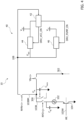
- FIG. 5 is a circuit block diagram exemplary of a bit line biasing architecture 50 that includes voltage detector 42, LDO regulator 44, and a sense amplifier circuit 52 that, in addition to performing conventional sensing function with a sense amplifier core 30' (e.g., a SA core 30 as disclosed with reference to Figure 3 ), implements a bit line voltage boosting function when demanded.
- a sense amplifier core 30' e.g., a SA core 30 as disclosed with reference to Figure 3
- circuit 52 may include various types of sense amplifier cores. Therefore, circuit 52 may include a SA core 30 such as the one illustrated in Figure 3 , or a different type of SA core (e.g., still latch-based but having a different internal architecture and functioning).
- the voltage detector 42 and the LDO regulator 44 are biased by the memory supply voltage Vcc (whose value can be, for example, in the range of 1.62 V to 3.6 V), while the sense amplifier 52 is biased by a low supply voltage V DD (whose value can be, for example, in the range of 0.75 V to 1.1 V).
- the voltage detector 42 is configured to sense the regulated voltage V REG at node 108 and the memory supply voltage Vcc, and is configured to determine whether the memory supply voltage Vcc is higher or lower than the expected (e.g., target or required) bit line voltage V BL_CHARGE (e.g., 1.76 V).
- detector 42 sets an activation signal LOW_VCC_EN of LDO regulator 44 to a first value (e.g., logic zero, de-asserted), which results in the LDO regulator 44 being activated to regulate its output voltage V REG to the target bit line voltage V BL_CHARGE (e.g., 1.76 V).
- LDO regulator 44 provides current from rail Vcc to node 108 to pre-charge the bit line capacitance(s) C BL , C MAIN at voltage V BL_CHARGE . In this condition, the entire pre-charge current may be provided by the LDO regulator 44 only.
- detector 42 disables the boost activation signal YMPS_PRECH_BST of the sense amplifier 52, which results in the bit line voltage boosting function of sense amplifier 52 being disabled (e.g., sense amplifier 52 only operates to sense the voltage at the bit lines).
- Vcc 1.6 V
- detector 42 sets the activation signal LOW_VCC_EN of LDO regulator 44 to a second value (e.g., logic one, asserted), which results in the LDO regulator 44 being activated to regulate its output voltage V REG to the maximum voltage available (i.e., as close as possible to Vcc, possibly equal to Vcc, for instance ⁇ 1.6 V), and sets the boost activation signal YMPS_PRECH_BST of the sense amplifier 52 to a first value (e.g., logic one, asserted), which results in the sense amplifier circuit 52 charging one or more internal boosting capacitors (as described more in detail in the following).
- a second value e.g., logic one, asserted
- LDO regulator 44 provides current from rail Vcc to node 108 to partially pre-charge the bit line capacitance(s) C BL , C MAIN at voltage V. In this condition, a portion of the pre-charge current is provided by the LDO regulator 44.
- detector 42 sets the boost activation signal YMPS_PRECH_BST of the sense amplifier 52 to a second value (e.g., logic zero, de-asserted) which results in the LDO regulator 44 being disconnected from nodes 304 L and 304 R and the internal boosting capacitors of the sense amplifier 52 providing charge to the bit lines to complete the pre-charge of the bit lines at voltage V BL_CHARGE or above it.
- a second value e.g., logic zero, de-asserted
- the energy (e.g., current) used to complete the pre-charge of the bit lines is taken from the LDO regulator 44, as further discussed in the following.
- the bit line voltage boosting function of sense amplifier 52 may be activated only if the supply voltage Vcc is lower than (or equal to) the target bit line voltage V BL_CHARGE , e.g., if Vcc ⁇ 1.76 V.
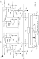
- Figure 6 is a circuit diagram exemplary of a reading architecture in a PCM memory bank 10B that implements the functionality described with reference to Figure 5 .
- the sense amplifier circuit 52 is coupled to nodes 304 L and 304 R and includes a sense amplifier core such as core 30 (e.g., as discussed with reference to Figure 3 ), and further includes a bit line voltage boosting circuit.
- the sense amplifier circuit 52 is supplied by the low supply voltage V DD (not visible in Figure 6 for ease of illustration).
- the bit line voltage boosting circuit is coupled between nodes 304 L and 304 R (e.g., in parallel to the sense amplifier core 30).
- a first boosting capacitor C BSTL has a first terminal coupled to node 304 L and a second terminal coupled to a node 62
- a second boosting capacitor C BSTR has a first terminal coupled to node 304 R and a second terminal coupled to node 62.
- the first terminal of capacitor C BSTL is selectively couplable, via a switch SL, to the regulated voltage V REG produced by the LDO 44.
- the first terminal of capacitor C BSTR is selectively couplable, via a switch SR, to the regulated voltage V REG produced by the LDO 44.
- Switches SL and SR are controlled by the boost activation signal YMPS_PRECH_BST (e.g., are both closed if signal YMPS_PRECH_BST has the first value (e.g., logic one, asserted) and are both open if signal YMPS_PRECH_BST has the second value (e.g., logic zero, de-asserted)).
- the bit line voltage boosting circuit further includes an inverter 64 having its input terminal configured to receive signal YMPS_PRECH_BST and its output terminal coupled to node 62. Inverter 64 is supplied by the regulated voltage V REG produced by the LDO 44. Therefore, the complement signal YMPS_PRECH_BST_N of the boost activation signal YMPS_PRECH_BST is produced at node 62.
- Read operation in a memory 10 as exemplified in Figure 6 may be carried out according to the procedure described in the following, which may be better understood by referring to the time diagram of Figure 7 that includes waveforms of signals during such a read operation.
- the main bit lines e.g., all nodes 300 L and 300 R
- the main bit lines are connected to the supply voltage rail 108 and charged by the LDO regulator 44 to the voltage V REG (e.g., about 1.6 V). Therefore, the main bit lines are partially pre-charged, i.e., the respective capacitances C MAIN are charged from ground voltage to voltage V REG (see voltage V MAIN,BL in Figure 7 ).
- the word line signal WL applied to the word line 103W is also driven to the voltage V REG .
- sensing node 302 L is connected to the input node 304 L of the sense amplifier 52 by closing switch SW YMPS,L
- sensing node 302 R is connected to the input node 304 R of the sense amplifier 52 by closing switch SW YMPS,R .
- the boost activation signal YMPS_PRECH_BST is driven to its first value (e.g., asserted, high) so that switches SL and SR are closed, the voltage YMPS_PRECH_BST_N at node 62 is low (e.g., ground) and thus capacitors C BSTL and C BSTR are charged at voltage V REG by the LDO regulator 44.
- the remaining switches are open during the first phase, that is: all the main bit lines (e.g., nodes 300) are decoupled from the respective sensing node 302, all the bit lines are decoupled from the respective node 300 (at this stage), and switches SW1 and SW2 are open as well.
- all the main bit lines e.g., nodes 300
- all the bit lines are decoupled from the respective node 300 (at this stage)
- switches SW1 and SW2 are open as well.
- a second phase (e.g., still P1 in Figure 7 ) switches SW1 and SW2 are closed. In this phase, input offset of the sense amplifier is compensated.
- a selected bit line pertaining to the left group is connected to the corresponding main bit line (e.g., node 300 L ) by closing the respective switch via signal NYO ⁇ j>.
- the corresponding selected bit line pertaining to the right group is connected to the corresponding main bit line (e.g., node 300 R ) by closing the respective switch via signal NYO ⁇ j>. Therefore, the selected bit lines are partially pre-charged, i.e., the respective capacitances C BL are charged from voltage V BE (e.g., about 0.6 V) to voltage V REG (see voltage V BL in Figure 7 ).
- a fourth phase (e.g., still P2 in Figure 7 ) one of nodes 300 L of the left group and the corresponding (e.g., homologous, symmetrical) node 300 R of the right group are disconnected from the supply voltage node 108 by opening the respective switches controlled by signals NYN ⁇ i>. Also, those main bit lines (nodes 300 L and 300 R ) are connected to the sensing nodes 302 L and 302 R , respectively, thereby selecting the main bit lines for reading.
- a fifth phase (e.g., P3 in Figure 7 ) the word line signal WL applied to a certain word line 103W is driven to ground voltage, thereby activating the selection transistors 104 and performing the actual word line selection (i.e., selection of two specific memory cells 102 L and 102 R ).
- the boost activation signal YMPS_PRECH_BST is driven to its second value (e.g., de-asserted, low) so that switches SL and SR are opened, the voltage YMPS_PRECH_BST_N at node 62 is forced to a high value (e.g., V REG ) and the charge stored in capacitors C BSTL and C BSTR at least partially redistributes towards nodes 300 L and 300 R , respectively.
- V REG a high value
- the voltage at the selected bit lines at the end of the pre-charge phase P3 depends on the sizing of the boosting capacitors C BSTL and C BSTR , which may be designed to have the same capacitance (e.g., about 31 fF in one or more embodiments).
- the capacitive nodes 300 L and 300 R (e.g., the bit line capacitances C BL and the main bit line capacitances C MAIN ) start discharging and the voltage at nodes 300 L and 300 R drops during the discharge window. Duration of the discharge window is supposed to be short (e.g., 1.5 ns).
- switches SW YMPS,L and SW YMPS,R are opened to disconnect the sense amplifier 52 from the memory array.
- Switches SW1 and SW2 of the sense amplifier core 30' are opened as well. In this state, sensing of a differential signal is carried out by the sense amplifier core 30'.
- One or more embodiments as exemplified herein may thus provide a bit line pre-charge architecture that does not include a charge pump circuit for boosting the bit line voltage, insofar as voltage boosting is implemented by a dedicated circuit in the sense amplifier.
- An advantage of such a new architecture is a lower power consumption compared to conventional solutions based on a charge pump.
- V REG 1.6 V
- V BL_CHARGE 1.76 V
- V EB 0.6 V
- C BL 108 fF
- C MAIN 174 fF
- C BST 31 fF
- the current consumption of a conventional architecture may be about 0.67 ⁇ A/MHz per each sense amplifier
- the power consumption of the architecture exemplified in Figure 6 may be about 0.416 ⁇ A/MHz per each sense amplifier, resulting in a current saving of about 38% per each sense amplifier.
- Another advantage of such a new architecture is a lower area compared to conventional solutions based on a charge pump. For instance, considering that the driving capability of a charge pump should grant a reading frequency of 100 MHz for 296 sense amplifiers (e.g., 2*(128+17+3) sense amplifiers) insofar as two banks of amplifiers read in parallel 128 bits of data plus 17 ECC bits plus 3 bits of redundancy, the total capacitance required for implementing the charge pump may be about 29.45 pF, while the total capacitance of the architecture exemplified in Figure 6 may be about 18.35 pF, resulting in an area reduction equivalent to removal of about 37% of the total capacitance.
Landscapes
- Chemical & Material Sciences (AREA)
- Crystallography & Structural Chemistry (AREA)
- Dram (AREA)
Abstract
Description
- The description relates to circuits and methods for biasing the bit lines of a memory device via a sense amplifier circuit.
- Such sense amplifiers may be used, for instance, during read operation from nonvolatile memories (NVM) such as embedded phase-change memories (embedded PCM, ePCM). Such memories may be applied, for instance, to general-purpose microcontrollers (GP MCU) and secure microcontrollers.
- Read operations (e.g., fetching of data) from phase-change memories are used to output (e.g., fetch, extract) the content of PCM data words on an output data bus (e.g., a 145-bit bus DATA_OUT[144:0]).
-
Figure 1 is a (simplified) circuit diagram exemplary of a reading architecture in a PCM memory, andFigure 2 is a time diagram including waveforms of signals during a read operation in the architecture ofFigure 1 . As exemplified inFigure 1 , amemory 10 includes an array of memory cells 102 (e.g., phase-change memory cells) arranged inbit lines 103B (here illustrated as vertical lines) andword lines word lines 103W) according to a memory architecture known per se. In particular, eachmemory cell 102 may be arranged in series to a respective selection transistor 104 (e.g., a pnp BJT transistor) between a ground voltage terminal and therespective bit line 103B. Theselection transistors 104 of thesame word line 103W receive the same control signal at their control (e.g., base) terminals, e.g., control signals WL1, WL2, WL3 as exemplified inFigures 1 and2 . Eachbit line 103B may be selectively coupled (e.g., via a respective p-channel MOS transistor 106 having its current path in series to the bit line and receiving a control signal Y_SEL) to a memorysupply voltage rail 108 that provides a regulated voltage VREG (e.g., having a target value VBL_CHARGE). Additionally, respective clamping transistors 110 (e.g., pnp BJT transistors) may be coupled between eachbit line 103B (e.g., at the source terminals of transistors 106) and the ground terminal. Theclamping transistors 110 may receive the same control signal WLCLAMP at their control (e.g., base) terminals. Eachbit line 103B has a respective capacitive load CBL due to the capacitances of thememory cells 102 and/or of thetransistors - As anticipated, a read operation in a phase-change memory as exemplified in
Figure 1 may be carried out as exemplified inFigure 2 to read (and provide as output) the content of plural PCM words on an output data bus DATA_OUT[144:0], Generally, in a phase-change memory, information may be stored associating two cells to each bit: a SET cell (having low resistance and high current) and a RESET cell (having high resistance and low current). A memory sense circuit may read information from the cells in differential mode. - In order to provide fast reading of the memory cells, the specification for the memory access time (TACC) may be particularly demanding (e.g., in the order of 10 ns). Additionally, read parallelism (e.g., reading two words in parallel) may be used to increase the throughput of the output data. As stated previously, sensing of the content of the memory cells may be carried out in differential mode: a sensing circuit reads in differential mode from the bit line BL_SET and the bit line BL_RESET, so that the SET memory cell and the RESET memory cell are selected. The SET memory cell and the RESET memory cell are selected by properly driving the control signals (word selection signals) WL1, WL2, WL3: for instance, as exemplified in
Figure 2 , by keeping signals WL1 and WL3 at a high logic value (e.g., equal to value VBL_CHARGE) and by driving signal WL2 to a low logic value (e.g., equal to the ground voltage, 0 V),cell 102S is selected as the SET cell andcell 102R is selected as the RESET cell. - A voltage regulator (e.g., a low-dropout, LDO, regulator) produces the regulated voltage VREG at the supply rail 108 (e.g., having a target voltage value VBL_CHARGE). The value VBL_CHARGE of voltage VREG should be high enough to provide a proper voltage stack to the bit lines to result in the correct values of the memory cells currents. Before sensing (e.g., differentially between BL_SET and BL_RESET), the voltage VBL at the selected bit lines is clamped to the value VBE of the base-emitter voltage of the
clamping transistors 110, and then the bit lines are pre-charged to the value VBL_CHARGE by the regulated voltage VREG by activating the transistors 106 (see inFigure 2 the control signal WLCLAMP switching from a low value to a high value VBL_CHARGE to switch offtransistors 110 and the control signal Y_SEL switching from a high value VBL_CHARGE to a low value to switch on transistors 106). The control signals WL1 and WL3 of the unselected word lines are kept at a high voltage value (e.g., VBL_CHARGE) so as to keep the respective selection transistors in a nonconductive state. - Embedded phase-change memories with BJT selectors as exemplified herein may thus rely on the bit lines being biased (e.g., pre-charged) to a target voltage level VBL_CHARGE at each read operation. The current required for pre-charging the bit lines (i.e., pre-charge the capacitances CBL) is provided by the LDO regulator if the supply voltage Vcc is higher than the expected (e.g., target or required) voltage VBL_CHARGE. In this case, the LDO regulator provides the current directly from the supply rail Vcc to prevent high current consumption. However, the value of the target voltage VBL_CHARGE may be approximately equal to 1.76 V, that is, higher than the minimum supply voltage VCCMIN that may be approximately equal to 1.62 V, for different reasons (e.g., to increase the SET-RESET distance in order to enlarge the reading window for improving the reliability margins, and/or to increase the reading margin versus noise and speed requirements). In case the target voltage VBL_CHARGE is higher than VCCMIN, the LDO regulator may be unable to satisfy such a requirement, and a charge pump (CP) may be integrated in the LDO regulator to provide a boosted voltage (i.e., higher than VCCMIN). However, activation of the charge pump may result in a relevant increase of the current consumption. For instance, current consumption during read operations may be almost doubled when the charge pump is activated.
- Therefore, there is a need in the art to provide improved reading architectures for phase-change memories, in particular providing improved sense amplifiers that allow boosting the bit line voltage to a value higher than the minimum supply voltage VCCMIN with reduced current consumption and/or reduced area consumption.
- An object of one or more embodiments is to contribute in providing such improved sense amplifiers for phase-change memories.
- According to one or more embodiments, such an object can be achieved by a sense amplifier circuit having the features set forth in the claims that follow.
- One or more embodiments may relate to a corresponding memory device.
- One or more embodiments may relate to a corresponding method of operation (e.g., a memory reading method).
- The claims are an integral part of the technical teaching provided herein in respect of the embodiments.
- According to an aspect of the present description, a sense amplifier circuit for a memory device includes a first input terminal and a second input terminal configured for coupling to a first memory sensing node and a second memory sensing node, respectively. A sensing circuit is coupled to the first and second input terminals and is configured to sense a differential signal therebetween. A first boosting capacitor has a first terminal coupled to the first input terminal and a second terminal coupled to a floating node. A second boosting capacitor has a first terminal coupled to the second input terminal and a second terminal coupled to the floating node. A control circuitry is configured to receive a bit line boosting activation signal. In response to the bit line boosting activation signal having a first value, the first terminals of the first and second boosting capacitors are coupled to a regulated supply node that provides a regulated supply voltage and the floating node is driven to a ground voltage. In response to the bit line boosting activation signal having a second value, the first terminals of the first and second boosting capacitors are decoupled from the regulated supply node and the floating node is driven to the regulated supply voltage.
- One or more embodiments may thus provide a sense amplifier circuit that facilitates boosting the pre-charge voltage of the bit lines, without resorting to a charge pump circuit integrated in the voltage regulator that supplies the memory device.
- According to another aspect of the present description, a memory device includes a plurality of memory banks. Each memory bank is coupled to a respective sense amplifier circuit according to one or more embodiments. Each memory bank includes an array of memory cells arranged in a plurality of bit lines and a plurality of word lines. Each memory cell is arranged in series to a respective selection transistor between a ground terminal and the corresponding bit line, and each bit line is selectively couplable to a regulated supply node that provides a regulated supply voltage, or to one of the first and second memory sensing nodes. A voltage detector circuit is configured to sense a system supply voltage and to detect whether the system supply voltage is higher than a threshold (e.g., a target bit line pre-charge voltage). A voltage regulator circuit is coupled to the system supply voltage and is configured to produce the regulated supply voltage at the regulated supply node. The voltage detector circuit is further configured to set an LDO activation signal to a first value and disable the bit line boosting activation signal in response to the system supply voltage being higher than the threshold. The voltage detector circuit is further configured to set the LDO activation signal to a second value and enable the bit line boosting activation signal in response to the system supply voltage being lower than or equal to the threshold. The voltage detector circuit is further configured to set the bit line boosting activation signal to the first value as long as the bit lines are coupled to the regulated supply node. The voltage detector circuit is further configured to set the bit line boosting activation signal to the second value in response to a pair of selected bit lines being coupled to the first and second memory sensing nodes, respectively. The voltage regulator circuit is configured to regulate the regulated supply voltage to a value equal to the threshold in response to the LDO activation signal having the first value, and regulate the regulated supply voltage to a value as close as possible to the system supply voltage in response to the LDO activation signal having the second value.
- According to another aspect of the present description, a method of operating a memory device according to one or more embodiments includes:
- sensing the system supply voltage and detecting whether the system supply voltage is higher than a threshold;
- in response to the system supply voltage being higher than the threshold, setting the LDO activation signal to the first value, regulating the regulated supply voltage to a value equal to the threshold, and disabling the bit line boosting activation signal;
- in response to the system supply voltage being lower than or equal to the threshold:
- i) setting the LDO activation signal to the second value, thereby regulating the regulated supply voltage to a value as close as possible to the system supply voltage;
- ii) setting the bit line boosting activation signal to the first value as long as the bit lines are coupled to the regulated supply node, thereby coupling the first terminals of the first and second boosting capacitors to the regulated supply node and driving the floating node to a ground voltage; and
- iii) setting the bit line boosting activation signal to the second value in response to a pair of selected bit lines being coupled to the first and second memory sensing nodes, respectively, thereby decoupling the first terminals of the first and second boosting capacitors from the regulated supply node and driving the floating node to the regulated supply voltage.
- One or more embodiments will now be described, by way of example, with reference to the annexed figures, wherein:
-
Figure 1 , previously presented, is a simplified circuit diagram exemplary of a reading architecture in a PCM memory; -
Figure 2 , previously presented, is a time diagram including waveforms of signals during a read operation in the architecture ofFigure 1 ; -
Figure 3 is a circuit diagram exemplary of a reading architecture in a PCM memory; -
Figure 4 is a circuit block diagram exemplary of a bit line biasing circuit; -
Figure 5 is a circuit block diagram exemplary of a bit line biasing circuit according to one or more embodiments of the present description; -
Figure 6 is a circuit diagram exemplary of a reading architecture in a PCM memory according to one or more embodiments of the present description; and -
Figure 7 is a time diagram including waveforms of signals during a read operation in the architecture ofFigure 6 . - In the ensuing description, one or more specific details are illustrated, aimed at providing an in-depth understanding of examples of embodiments of this description. The embodiments may be obtained without one or more of the specific details, or with other methods, components, materials, etc. In other cases, known structures, materials, or operations are not illustrated or described in detail so that certain aspects of embodiments will not be obscured.
- Reference to "an embodiment" or "one embodiment" in the framework of the present description is intended to indicate that a particular configuration, structure, or characteristic described in relation to the embodiment is included in at least one embodiment. Hence, phrases such as "in an embodiment" or "in one embodiment" that may be present in one or more points of the present description do not necessarily refer to one and the same embodiment. Moreover, particular configurations, structures, or characteristics may be combined in any adequate way in one or more embodiments.
- The headings/references used herein are provided merely for convenience and hence do not define the extent of protection or the scope of the embodiments.
- Throughout the figures annexed herein, unless the context indicates otherwise, like parts or elements are indicated with like references/numerals and a corresponding description will not be repeated for the sake of brevity.
- By way of introduction to the detailed description of exemplary embodiments, reference may first be made to
Figure 3 , which is a circuit diagram exemplary of a reading architecture of aPCM memory bank 10B. It will be noted that for ease of illustration, asingle word line 103W is visible inFigure 3 , and plural bit lines 103B. It will also be noted that certain elements of the array of thememory bank 10B are illustrated only once for ease of illustration as well. The bit lines are arranged in two main groups (e.g., a left group and a right group), with the two main groups including the same number of bit lines (e.g., 16 bit lines), in order to allow differential reading. During read operations, a differential voltage is sensed between two bit lines (a SET line and a RESET line), one belonging to the left group and the other belonging to the right group. The two main groups are each subdivided in a number n of subgroups or "main bit lines" 103BM, e.g., 2 subgroups, each subgroup including a number m of bit lines, e.g., 8 bit lines. Each main bit line has an associated parasitic capacitance CMAIN (e.g., CMAIN,L for the main bit lines in the left group and CMAIN,R for the main bit lines in the right group). The bit lines 103B of the same main bit line 103BM are arranged in parallel between a respective common node 300 (e.g.,nodes 300L for the main bit lines in the left group andnodes 300R for the main bit lines in the right group) and ground, and are selectively couplable to thecommon node 300 via respective switches arranged in series to the bit lines. These switches are controlled by respective selection signals NYO (e.g., NYO<j>, ..., with j = 1, ..., m). Each common node 300 (e.g., each main bit line) is selectively couplable via respective switches either to thesupply voltage rail 108 at voltage VREG or to a respective sensing node 302 (e.g., aleft sensing node 302L for the main bit lines of the left group and aright sensing node 302R for the main bit lines of the right group). In particular, a first main bit line in the left group and a first main bit line in the right group can be coupled to rail 108 depending on the value of signal NYN<i>, a second main bit line in the left group and a second main bit line in the right group can be coupled to rail 108 depending on the value of signal NYN<i+1>, and so on (with i = 1, ..., n). In a similar way, two main bit lines at a time (one from the left group and the other from the right group) can be coupled to therespective sensing nodes differential input nodes Node 304L is selectively couplable tonode 302L via a switch SWYMPS,L, andnode 304R is selectively couplable tonode 302R via a switch SWYMPS,R. In particular, switches SWYMPS,L and SWYMPS,R are configured to isolatenodes nodes Nodes sense amplifier 30 has a first terminal coupled tonode 304L and a second terminal coupled to anode 306L, and a second input capacitor CINR of thesense amplifier 30 has a first terminal coupled tonode 304R and a second terminal coupled to anode 306R. Thesense amplifier core 30 further includes: a first inverter INV1 having an input terminal coupled tonode 306L and an output terminal coupled to anode 308R, a first capacitor CR coupled betweennodes node 306R and an output terminal coupled to anode 308L, a second capacitor CL coupled betweennodes Figure 3 for ease of illustration). Switches SW1 and SW2 may be controlled by the same equalization signal EQ (not visible inFigure 3 for ease of illustration). - Read operation in a
memory bank 10B as exemplified inFigure 3 may be carried out according to the procedure described in the following. - In a first step, the main bit lines (e.g., all
nodes 300L and 300R) are connected to thesupply voltage rail 108 and charged by voltage VREG to the target value VBL_CHARGE (e.g., about 1.7 V). The word line signal WL applied to theword line 103W is also driven to the value VBL_CHARGE. Additionally, signals YN<i>, YN<i+1>, ... are set so as to connect one ofnodes 300L of the left group and the corresponding (e.g., homologous, symmetrical)node 300R of the right group to thesensing nodes node 302L is connected to theinput node 304L of thesense amplifier core 30 by closing switch SWYMPS,L, andsensing node 302R is connected to theinput node 304R of thesense amplifier core 30 by closing switch SWYMPS,R. The remaining switches are open during the first step, that is: allnodes 300 that do not correspond to a selected main bit line are decoupled from therespective sensing node 302, all the bit lines are decoupled from the respective node 300 (at this stage), and switches SWCONNECT, SW1 and SW2 of thesense amplifier core 30 are open as well. The enable signal EN_SA is set at a value that switches off the inverters INV1 and INV2, i.e., it is de-asserted (e.g., set to a low logic value, ground voltage, 0 V). - In a second step, switches SW1 and SW2 are closed (e.g., equalization signal EQ is asserted) and enable signal EN_SA is asserted (e.g., set to a high logic value) so as to activate inverters INV1 and INV2. In this step, input offset of the
sense amplifier core 30 is compensated and the input capacitors CINL, CINR are pre-charged. - In a third step, a selected bit line pertaining to the left group and to the selected main bit line (i.e., the left main bit line that is currently connected to node 302L) is connected to the corresponding main bit line (e.g., node 300L) by closing the respective switch via signal NYO<j>. Similarly, the corresponding selected bit line pertaining to the right group and to the selected main bit line (i.e., the right main bit line that is currently connected to node 302R) is connected to the corresponding main bit line (e.g., node 300R) by closing the respective switch via signal NYO<j>. By doing so, the selected bit lines are pre-charged, i.e., the respective capacitances CBL are charged from voltage VBE (e.g., about 0.6 V) to the target voltage VBL_CHARGE.
- In a fourth step, the selected main bit lines (left and right) are disconnected from the
supply voltage rail 108 by opening the respective switches controlled by signals NYN<i>. - In a fifth step, the word line signal WL applied to a
certain word line 103W is driven to ground voltage, thereby activating theselection transistors 104 and carrying out the actual word line selection (i.e., selection of twospecific memory cells 102L and 102R). As a result,capacitive nodes 300L and 300R (e.g., the bit line capacitances CBL and the main bit line capacitances CMAIN) start discharging and the voltage atnodes 300L and 300R (that are connected to thesensing nodes 302L and 302R) drops during a so-called "discharge window". At the same time, capacitor CINL is charged to a certain voltage VLEFT and capacitor CINR is charged to a certain voltage VRIGHT depending on the resistance of thememory cells - In a sixth step, switches SWYMPS,L and SWYMPS,R are opened to disconnect the sense amplifier core 30 (whose input terminals have been charged) from the memory array. Switches SW1 and SW2 are opened as well, and switch SWCONNECT is closed. In this state, sensing of the differential voltage (e.g., difference between VLEFT and VRIGHT) is carried out by the
sense amplifier core 30. - As anticipated, a reading architecture as exemplified in
Figure 3 may thus rely on the provision of a charge pump circuit to produce the target voltage VBL_CHARGE when this is higher than the supply voltage Vcc (which also biases the LDO regulator). For instance,Figure 4 is a circuit block diagram exemplary of such a conventional bitline biasing architecture 40.Biasing architecture 40 includes avoltage detector 42, anLDO regulator 44, and acharge pump circuit 46, all biased by the memory supply voltage Vcc. Thevoltage detector 42 is configured to sense the voltage VREG atnode 108 and the voltage Vcc, and is configured to determine whether the supply voltage Vcc is higher or lower than the expected (e.g., target or required) bit line voltage VBL_CHARGE. If the supply voltage Vcc is higher than the target bit line voltage VBL_CHARGE,detector 42 asserts an enable signal DRV_VCC_EN to activate theLDO regulator 44, which then provides current from rail Vcc tonode 108 to pre-charge the bit line capacitance(s) CBL, CMAIN at voltage VBL_CHARGE. If the supply voltage Vcc is lower than (or equal to) the target bit line voltage VBL_CHARGE,detector 42 asserts an enable signal DRV_PUMP_EN to activate thecharge pump circuit 46, which then provides current from rail Vcc tonode 108 to pre-charge the bit line capacitance(s) CBL, CMAIN at voltage VBL_CHARGE. The inefficiency (e.g., the ratio between the input and output currents) of theLDO regulator 44 may be equal to about 1.05, while the inefficiency of thecharge pump circuit 46 may be equal to about 2.6 (e.g., in the case of a one-stage charge pump). Therefore, the current consumption during read operations may be almost doubled when thecharge pump 46 is activated. Further, the voltage threshold that determines the activation of the charge pump by detector 42 (i.e., switching from LDO to CP operation) may depend on the process, may be linked to the BJT threshold and may thus range from about 1.6 V to about 1.8 V. - Therefore, it is desirable to provide improved reading architectures that allow boosting the bit line voltage to a value higher than the supply value Vcc without resorting to a charge pump circuit. In particular, this may be achieved by providing improved sense amplifiers that implement a bit line voltage boosting function.
- One or more embodiments thus rely on an architecture as exemplified in
Figure 5 , which is a circuit block diagram exemplary of a bit line biasing architecture 50 that includesvoltage detector 42,LDO regulator 44, and asense amplifier circuit 52 that, in addition to performing conventional sensing function with a sense amplifier core 30' (e.g., aSA core 30 as disclosed with reference toFigure 3 ), implements a bit line voltage boosting function when demanded. It is noted that in the architecture ofFigure 5 (and followingFigure 6 ) thesense amplifier 52 may include various types of sense amplifier cores. Therefore,circuit 52 may include aSA core 30 such as the one illustrated inFigure 3 , or a different type of SA core (e.g., still latch-based but having a different internal architecture and functioning). This is also exemplified by the fact that the architecture ofFigure 6 does not include the switch SWCONNECT betweennodes sense amplifier 52 of the instant application. - The
voltage detector 42 and theLDO regulator 44 are biased by the memory supply voltage Vcc (whose value can be, for example, in the range of 1.62 V to 3.6 V), while thesense amplifier 52 is biased by a low supply voltage VDD (whose value can be, for example, in the range of 0.75 V to 1.1 V). Thevoltage detector 42 is configured to sense the regulated voltage VREG atnode 108 and the memory supply voltage Vcc, and is configured to determine whether the memory supply voltage Vcc is higher or lower than the expected (e.g., target or required) bit line voltage VBL_CHARGE (e.g., 1.76 V). - If the memory supply voltage VCC is higher than the target bit line voltage VBL_CHARGE,
detector 42 sets an activation signal LOW_VCC_EN ofLDO regulator 44 to a first value (e.g., logic zero, de-asserted), which results in theLDO regulator 44 being activated to regulate its output voltage VREG to the target bit line voltage VBL_CHARGE (e.g., 1.76 V). Thus,LDO regulator 44 provides current from rail Vcc tonode 108 to pre-charge the bit line capacitance(s) CBL, CMAIN at voltage VBL_CHARGE. In this condition, the entire pre-charge current may be provided by theLDO regulator 44 only. At the same time,detector 42 disables the boost activation signal YMPS_PRECH_BST of thesense amplifier 52, which results in the bit line voltage boosting function ofsense amplifier 52 being disabled (e.g.,sense amplifier 52 only operates to sense the voltage at the bit lines). - If the memory supply voltage VCC is lower than (or equal to) the target bit line voltage VBL_CHARGE (e.g., Vcc = 1.6 V),
detector 42 enables the boost activation signal YMPS_PRECH_BST of thesense amplifier 52 and the bit line pre-charge is carried out in two phases or steps. In the first step,detector 42 sets the activation signal LOW_VCC_EN ofLDO regulator 44 to a second value (e.g., logic one, asserted), which results in theLDO regulator 44 being activated to regulate its output voltage VREG to the maximum voltage available (i.e., as close as possible to Vcc, possibly equal to Vcc, for instance ~1.6 V), and sets the boost activation signal YMPS_PRECH_BST of thesense amplifier 52 to a first value (e.g., logic one, asserted), which results in thesense amplifier circuit 52 charging one or more internal boosting capacitors (as described more in detail in the following). Thus,LDO regulator 44 provides current from rail Vcc tonode 108 to partially pre-charge the bit line capacitance(s) CBL, CMAIN at voltage V. In this condition, a portion of the pre-charge current is provided by theLDO regulator 44. In the second step,detector 42 sets the boost activation signal YMPS_PRECH_BST of thesense amplifier 52 to a second value (e.g., logic zero, de-asserted) which results in theLDO regulator 44 being disconnected fromnodes sense amplifier 52 providing charge to the bit lines to complete the pre-charge of the bit lines at voltage VBL_CHARGE or above it. Therefore, the pre-charge may be completed by thesense amplifier 52 during (e.g., at the beginning of) the sensing phase by further increasing the bit line voltage VBL by an amount indicated as ΔVSA (e.g., ΔVSA = 0.16 V). The energy (e.g., current) used to complete the pre-charge of the bit lines is taken from theLDO regulator 44, as further discussed in the following. It is noted that, in order to reduce power consumption, the bit line voltage boosting function ofsense amplifier 52 may be activated only if the supply voltage Vcc is lower than (or equal to) the target bit line voltage VBL_CHARGE, e.g., if Vcc ≤ 1.76 V. -
Figure 6 is a circuit diagram exemplary of a reading architecture in aPCM memory bank 10B that implements the functionality described with reference toFigure 5 . In particular, thesense amplifier circuit 52 is coupled tonodes Figure 3 ), and further includes a bit line voltage boosting circuit. Thesense amplifier circuit 52 is supplied by the low supply voltage VDD (not visible inFigure 6 for ease of illustration). The bit line voltage boosting circuit is coupled betweennodes 304L and 304R (e.g., in parallel to the sense amplifier core 30). A first boosting capacitor CBSTL has a first terminal coupled tonode 304L and a second terminal coupled to anode 62, and a second boosting capacitor CBSTR has a first terminal coupled tonode 304R and a second terminal coupled tonode 62. The first terminal of capacitor CBSTL is selectively couplable, via a switch SL, to the regulated voltage VREG produced by theLDO 44. The first terminal of capacitor CBSTR is selectively couplable, via a switch SR, to the regulated voltage VREG produced by theLDO 44. Switches SL and SR are controlled by the boost activation signal YMPS_PRECH_BST (e.g., are both closed if signal YMPS_PRECH_BST has the first value (e.g., logic one, asserted) and are both open if signal YMPS_PRECH_BST has the second value (e.g., logic zero, de-asserted)). The bit line voltage boosting circuit further includes aninverter 64 having its input terminal configured to receive signal YMPS_PRECH_BST and its output terminal coupled tonode 62.Inverter 64 is supplied by the regulated voltage VREG produced by theLDO 44. Therefore, the complement signal YMPS_PRECH_BST_N of the boost activation signal YMPS_PRECH_BST is produced atnode 62. - Read operation in a
memory 10 as exemplified inFigure 6 may be carried out according to the procedure described in the following, which may be better understood by referring to the time diagram ofFigure 7 that includes waveforms of signals during such a read operation. - In a first phase (e.g., P1 in
Figure 7 ), the main bit lines (e.g., allnodes 300L and 300R) are connected to thesupply voltage rail 108 and charged by theLDO regulator 44 to the voltage VREG (e.g., about 1.6 V). Therefore, the main bit lines are partially pre-charged, i.e., the respective capacitances CMAIN are charged from ground voltage to voltage VREG (see voltage VMAIN,BL inFigure 7 ). The word line signal WL applied to theword line 103W is also driven to the voltage VREG . Additionally, sensingnode 302L is connected to theinput node 304L of thesense amplifier 52 by closing switch SWYMPS,L, andsensing node 302R is connected to theinput node 304R of thesense amplifier 52 by closing switch SWYMPS,R. The boost activation signal YMPS_PRECH_BST is driven to its first value (e.g., asserted, high) so that switches SL and SR are closed, the voltage YMPS_PRECH_BST_N atnode 62 is low (e.g., ground) and thus capacitors CBSTL and CBSTR are charged at voltage VREG by theLDO regulator 44. The remaining switches are open during the first phase, that is: all the main bit lines (e.g., nodes 300) are decoupled from therespective sensing node 302, all the bit lines are decoupled from the respective node 300 (at this stage), and switches SW1 and SW2 are open as well. - In a second phase (e.g., still P1 in
Figure 7 ), switches SW1 and SW2 are closed. In this phase, input offset of the sense amplifier is compensated. - In a third phase (e.g., P2 in
Figure 7 ), a selected bit line pertaining to the left group is connected to the corresponding main bit line (e.g., node 300L) by closing the respective switch via signal NYO<j>. Similarly, the corresponding selected bit line pertaining to the right group is connected to the corresponding main bit line (e.g., node 300R) by closing the respective switch via signal NYO<j>. Therefore, the selected bit lines are partially pre-charged, i.e., the respective capacitances CBL are charged from voltage VBE (e.g., about 0.6 V) to voltage VREG (see voltage VBL inFigure 7 ). - In a fourth phase (e.g., still P2 in
Figure 7 ), one ofnodes 300L of the left group and the corresponding (e.g., homologous, symmetrical)node 300R of the right group are disconnected from thesupply voltage node 108 by opening the respective switches controlled by signals NYN<i>. Also, those main bit lines (nodes 300L and 300R) are connected to thesensing nodes - In a fifth phase (e.g., P3 in
Figure 7 ), the word line signal WL applied to acertain word line 103W is driven to ground voltage, thereby activating theselection transistors 104 and performing the actual word line selection (i.e., selection of twospecific memory cells 102L and 102R). At the same time, the boost activation signal YMPS_PRECH_BST is driven to its second value (e.g., de-asserted, low) so that switches SL and SR are opened, the voltage YMPS_PRECH_BST_N atnode 62 is forced to a high value (e.g., VREG ) and the charge stored in capacitors CBSTL and CBSTR at least partially redistributes towardsnodes capacitive nodes 300L and 300R (e.g., the bit line capacitances CBL and the main bit line capacitances CMAIN) are boosted to the target reading voltage (e.g., VBL_CHARGE = 1.76 V, see voltages VMAIN,BL and VBL inFigure 7 ). The voltage at the selected bit lines at the end of the pre-charge phase P3 depends on the sizing of the boosting capacitors CBSTL and CBSTR, which may be designed to have the same capacitance (e.g., about 31 fF in one or more embodiments). Subsequently (e.g., P4 inFigure 7 ) thecapacitive nodes 300L and 300R (e.g., the bit line capacitances CBL and the main bit line capacitances CMAIN) start discharging and the voltage atnodes - In a sixth phase (e.g., still P4 in
Figure 7 ), switches SWYMPS,L and SWYMPS,R are opened to disconnect thesense amplifier 52 from the memory array. Switches SW1 and SW2 of the sense amplifier core 30' are opened as well. In this state, sensing of a differential signal is carried out by the sense amplifier core 30'. - One or more embodiments as exemplified herein may thus provide a bit line pre-charge architecture that does not include a charge pump circuit for boosting the bit line voltage, insofar as voltage boosting is implemented by a dedicated circuit in the sense amplifier.
- An advantage of such a new architecture is a lower power consumption compared to conventional solutions based on a charge pump. For instance, considering the following exemplary parameters VREG = 1.6 V, VBL_CHARGE = 1.76 V, VEB = 0.6 V, CBL = 108 fF, CMAIN = 174 fF, CBST = 31 fF, the current consumption of a conventional architecture may be about 0.67 µA/MHz per each sense amplifier, while the power consumption of the architecture exemplified in
Figure 6 may be about 0.416 µA/MHz per each sense amplifier, resulting in a current saving of about 38% per each sense amplifier. - Another advantage of such a new architecture is a lower area compared to conventional solutions based on a charge pump. For instance, considering that the driving capability of a charge pump should grant a reading frequency of 100 MHz for 296 sense amplifiers (e.g., 2*(128+17+3) sense amplifiers) insofar as two banks of amplifiers read in parallel 128 bits of data plus 17 ECC bits plus 3 bits of redundancy, the total capacitance required for implementing the charge pump may be about 29.45 pF, while the total capacitance of the architecture exemplified in
Figure 6 may be about 18.35 pF, resulting in an area reduction equivalent to removal of about 37% of the total capacitance. - Without prejudice to the underlying principles, the details and embodiments may vary, even significantly, with respect to what has been described by way of example, without departing from the extent of protection.
- The extent of protection is determined by the annexed claims.
Claims (6)
- A sense amplifier circuit (52) for a memory device (10), the sense amplifier circuit (52) comprising:a first input terminal (304L) and a second input terminal (304R) configured for coupling (SWYMPS,L, SWYMPS,R) to a first memory sensing node (302L) and a second memory sensing node (302R), respectively;a sensing circuit (30') coupled to the first (304L) and second (304R) input terminals and configured to sense a differential signal therebetween;a first boosting capacitor (CBSTL) having a first terminal coupled to the first input terminal (304L) and a second terminal coupled to a floating node (62);a second boosting capacitor (CBSTR) having a first terminal coupled to the second input terminal (304R) and a second terminal coupled to the floating node (62);control circuitry (64, SL, SR) configured to receive a bit line boosting activation signal (YMPS_PRECH_BST) and to:i) in response to said bit line boosting activation signal (YMPS_PRECH_BST) having a first value, couple the first terminals of said first (CBSTL) and second (CBSTR) boosting capacitors to a regulated supply node (108) that provides a regulated supply voltage (VREG ) and drive said floating node (62) to a ground voltage; andii) in response to said bit line boosting activation signal (YMPS_PRECH_BST) having a second value, decouple the first terminals of said first (CBSTL) and second (CBSTR) boosting capacitors from said regulated supply node (108) and drive said floating node (62) to said regulated supply voltage (VREG ).
- A sense amplifier circuit (52) according to claim 1, wherein said control circuitry (64, SL, SR) comprises:a first switch (SL) arranged between the first terminal of said first boosting capacitor (CBSTL) and said regulated supply node (108), the first switch (SL) being controlled by said bit line boosting activation signal (YMPS_PRECH_BST);a second switch (SR) arranged between the first terminal of said second boosting capacitor (CBSTR) and said regulated supply node (108), the second switch (SR) being controlled by said bit line boosting activation signal (YMPS_PRECH_BST); andan inverter circuit (64) having an input terminal controlled by said bit line boosting activation signal (YMPS_PRECH_BST) and an output terminal connected to said floating node (62), the inverter circuit (64) being biased by said regulated supply voltage (VREG ).
- A sense amplifier circuit (52) according to claim 1 or claim 2, wherein said sensing circuit (30') comprises:a first input capacitor (CINL) having a first terminal coupled to the first input terminal (304L) and a second terminal coupled to a first differential node (306L);a second input capacitor (CINR) having a first terminal coupled to the second input terminal (304R) and a second terminal coupled to a second differential node (306R);a first latched inverter circuit (INV1) having an input terminal coupled to the first differential node (306L) and an output terminal coupled to a first intermediate node (308R);a first intermediate capacitor (CR) coupled between the first intermediate node (308R) and the second differential node (306R);a second latched inverter circuit (INV2) having an input terminal coupled to the second differential node (306R) and an output terminal coupled to a second intermediate node (308L); anda second intermediate capacitor (CL) coupled between the second intermediate node (308L) and the first differential node (306L).
- A memory device (10) comprising a plurality of memory banks (10B), wherein each memory bank (10B) comprises:a sense amplifier circuit (52) according to any of the previous claims;an array of memory cells (102) arranged in a plurality of bit lines (103B) and a plurality of word lines (103W1, 103W2, 103W3), wherein each memory cell (102) is arranged in series to a respective selection transistor (104) between a ground terminal and the corresponding bit line (103B), and each bit line (103B) is selectively couplable (NYN<i>, YN<i>) to said regulated supply node (108) that provides a regulated supply voltage (VREG ), or to one of said first (302L) and second (302R) memory sensing nodes;a voltage detector circuit (42) configured to sense a system supply voltage (Vcc) and to detect whether said system supply voltage (VCC) is higher than a threshold (VBL_CHARGE);a voltage regulator circuit (44) coupled to said system supply voltage (Vcc) and configured to produce said regulated supply voltage (VREG ) at said regulated supply node (108);wherein said voltage detector circuit (42) is further configured to:i) in response to said system supply voltage (Vcc) being higher than said threshold (VBL_CHARGE), set an LDO activation signal (LOW_VCC_EN) to a first value and disable said bit line boosting activation signal (YMPS_PRECH_BST);ii) in response to said system supply voltage (Vcc) being lower than or equal to said threshold (VBL_CHARGE), set the LDO activation signal (LOW_VCC_EN) to a second value and enable said bit line boosting activation signal (YMPS_PRECH_BST);iii) set said bit line boosting activation signal (YMPS_PRECH_BST) to said first value as long as said bit lines (103B) are coupled (NYN<i>) to said regulated supply node (108); andiv) set said bit line boosting activation signal (YMPS_PRECH_BST) to said second value in response to a pair of selected bit lines being coupled (YN<i>) to said first (302L) and second (302R) memory sensing nodes, respectively;wherein said voltage regulator circuit (44) is configured to:i) in response to said LDO activation signal (LOW_VCC_EN) having said first value, regulate said regulated supply voltage (VREG ) to a value equal to said threshold (VBL_CHARGE); andii) in response to said LDO activation signal (LOW_VCC_EN) having said second value, regulate said regulated supply voltage (VREG ) to a value as close as possible to said system supply voltage (Vcc).
- A memory device (10) according to claim 4, wherein:said plurality of bit lines (103B) is arranged in two main groups including the same number of bit lines (103B);each of said two main groups includes a plurality of main bit lines (103BM, 300L, 300R), each main bit line including the same number of bit lines (103B);each memory cell (102) is selectively couplable to the respective main bit line (103BM, 300L, 300R) via a respective switch (NYO<j>); andeach main bit line (103BM, 300L, 300R) is selectively couplable (NYN<i>, YN<i>) to said regulated supply node (108) or to a respective one of said first (302L) and second (302R) memory sensing nodes.
- A method of operating a memory device (10) according to claim 4 or claim 5, the method comprising:sensing said system supply voltage (Vcc) and detecting whether said system supply voltage (Vcc) is higher than a threshold (VBL_CHARGE);in response to said system supply voltage (Vcc) being higher than said threshold (VBL_CHARGE), setting said LDO activation signal (LOW_VCC_EN) to said first value, regulating said regulated supply voltage (VREG ) to a value equal to said threshold (VBL_CHARGE), and disabling said bit line boosting activation signal (YMPS_PRECH_BST);in response to said system supply voltage (Vcc) being lower than or equal to said threshold (VBL_CHARGE):i) setting said LDO activation signal (LOW_VCC_EN) to said second value, thereby regulating said regulated supply voltage (VREG ) to a value as close as possible to said system supply voltage (Vcc);ii) setting said bit line boosting activation signal (YMPS_PRECH_BST) to said first value as long as said bit lines (103B) are coupled (NYN<i>) to said regulated supply node (108), thereby coupling the first terminals of said first (CBSTL) and second (CBSTR) boosting capacitors to said regulated supply node (108) and driving said floating node (62) to a ground voltage; andiii) setting said bit line boosting activation signal (YMPS_PRECH_BST) to said second value in response to a pair of selected bit lines being coupled (YN<i>) to said first (302L) and second (302R) memory sensing nodes, respectively, thereby decoupling the first terminals of said first (CBSTL) and second (CBSTR) boosting capacitors from said regulated supply node (108) and driving said floating node (62) to said regulated supply voltage (VREG ).
Applications Claiming Priority (1)
| Application Number | Priority Date | Filing Date | Title |
|---|---|---|---|
| IT202300011037 | 2023-05-31 |
Publications (2)
| Publication Number | Publication Date |
|---|---|
| EP4471773A1 true EP4471773A1 (en) | 2024-12-04 |
| EP4471773B1 EP4471773B1 (en) | 2025-12-10 |
Family
ID=87514109
Family Applications (1)
| Application Number | Title | Priority Date | Filing Date |
|---|---|---|---|
| EP24167364.9A Active EP4471773B1 (en) | 2023-05-31 | 2024-03-28 | Memory device comprising a sense amplifier circuit and method of operation |
Country Status (2)
| Country | Link |
|---|---|
| US (1) | US20240404595A1 (en) |
| EP (1) | EP4471773B1 (en) |
Citations (2)
| Publication number | Priority date | Publication date | Assignee | Title |
|---|---|---|---|---|
| US20190066805A1 (en) * | 2017-08-25 | 2019-02-28 | Silicon Storage Technology, Inc. | Sense Amplifier Circuit For Reading Data In A Flash Memory Cell |
| US20200168266A1 (en) * | 2017-08-24 | 2020-05-28 | Semiconductor Energy Laboratory Co., Ltd. | Sense amplifier, semiconductor device, operation method thereof, and electronic device |
Family Cites Families (8)
| Publication number | Priority date | Publication date | Assignee | Title |
|---|---|---|---|---|
| EP0189908B1 (en) * | 1985-01-30 | 1992-10-28 | Nec Corporation | Dynamic memory with improved arrangement for precharging bit lines |
| US5297097A (en) * | 1988-06-17 | 1994-03-22 | Hitachi Ltd. | Large scale integrated circuit for low voltage operation |
| KR0154755B1 (en) * | 1995-07-07 | 1998-12-01 | 김광호 | Semiconductor memory device having variable plate voltage generation circuit |
| US6373753B1 (en) * | 1999-02-13 | 2002-04-16 | Robert J. Proebsting | Memory array having selected word lines driven to an internally-generated boosted voltage that is substantially independent of VDD |
| JP3983969B2 (en) * | 2000-03-08 | 2007-09-26 | 株式会社東芝 | Nonvolatile semiconductor memory device |
| KR101338384B1 (en) * | 2007-12-10 | 2013-12-06 | 삼성전자주식회사 | Memory cell array and semiconductor memory device having the same |
| JP2011065693A (en) * | 2009-09-16 | 2011-03-31 | Toshiba Corp | Non-volatile semiconductor memory device |
| US9542995B2 (en) * | 2013-08-30 | 2017-01-10 | Manoj Sachdev | Threshold voltage mismatch compensation sense-amplifiers for static random access memories with multiple differential inputs |
-
2024
- 2024-03-28 EP EP24167364.9A patent/EP4471773B1/en active Active
- 2024-05-29 US US18/676,630 patent/US20240404595A1/en active Pending
Patent Citations (2)
| Publication number | Priority date | Publication date | Assignee | Title |
|---|---|---|---|---|
| US20200168266A1 (en) * | 2017-08-24 | 2020-05-28 | Semiconductor Energy Laboratory Co., Ltd. | Sense amplifier, semiconductor device, operation method thereof, and electronic device |
| US20190066805A1 (en) * | 2017-08-25 | 2019-02-28 | Silicon Storage Technology, Inc. | Sense Amplifier Circuit For Reading Data In A Flash Memory Cell |
Also Published As
| Publication number | Publication date |
|---|---|
| US20240404595A1 (en) | 2024-12-05 |
| EP4471773B1 (en) | 2025-12-10 |
Similar Documents
| Publication | Publication Date | Title |
|---|---|---|
| US6765828B2 (en) | Non-volatile semiconductor storage device and method of reading out data | |
| USRE39227E1 (en) | Content addressable memory (CAM) arrays and cells having low power requirements | |
| TWI231506B (en) | Reading circuit and semiconductor memory device including the same | |
| US8339884B2 (en) | Low power and high speed sense amplifier | |
| EP2299450B1 (en) | Sense-amplifier circuit for non-volatile memories that operates at low supply voltages | |
| US10199112B1 (en) | Sense amplifier circuit for reading data in a flash memory cell | |
| US7616028B2 (en) | Sense amplifier for low voltage high speed sensing | |
| US20060120175A1 (en) | Memory array with fast bit line precharge | |
| JP2001084782A (en) | Read circuit for nonvolatile memory | |
| CA2391331A1 (en) | Reference cell for high speed sensing in non-volatile memories | |
| CN111164691A (en) | Area efficient write data path circuit for SRAM yield enhancement | |
| KR930001735B1 (en) | Semiconductor memory device | |
| US6442054B1 (en) | Sense amplifier for content addressable memory | |
| US20080159005A1 (en) | Selective bit line precharging in non volatile memory | |
| US7158431B2 (en) | Single transistor sensing and double transistor sensing for flash memory | |
| US20170278552A1 (en) | Sense structure based on multiple sense amplifiers with local regulation of a biasing voltage | |
| US20060146609A1 (en) | NAND flash memory device and method of programming same | |
| EP4471773B1 (en) | Memory device comprising a sense amplifier circuit and method of operation | |
| US20050122808A1 (en) | Low voltage sense amplifier for operation under a reduced bit line bias voltage | |
| US20100208505A1 (en) | Anti-cross-talk circuitry for rom arrays | |
| US20080056024A1 (en) | Device and method for reading out memory information | |
| US7477559B2 (en) | Sense amplifier for low-voltage applications | |
| CN119068928A (en) | Sense amplifier circuit, corresponding memory device and operating method | |
| EP4471772B1 (en) | Sense amplifier circuit, corresponding memory device and method of operation | |
| EP1408509A2 (en) | Random access memory device and method for driving a plate line segment therein |
Legal Events
| Date | Code | Title | Description |
|---|---|---|---|
| PUAI | Public reference made under article 153(3) epc to a published international application that has entered the european phase |
Free format text: ORIGINAL CODE: 0009012 |
|
| STAA | Information on the status of an ep patent application or granted ep patent |
Free format text: STATUS: THE APPLICATION HAS BEEN PUBLISHED |
|
| AK | Designated contracting states |
Kind code of ref document: A1 Designated state(s): AL AT BE BG CH CY CZ DE DK EE ES FI FR GB GR HR HU IE IS IT LI LT LU LV MC ME MK MT NL NO PL PT RO RS SE SI SK SM TR |
|
| STAA | Information on the status of an ep patent application or granted ep patent |
Free format text: STATUS: REQUEST FOR EXAMINATION WAS MADE |
|
| 17P | Request for examination filed |
Effective date: 20250326 |
|
| GRAP | Despatch of communication of intention to grant a patent |
Free format text: ORIGINAL CODE: EPIDOSNIGR1 |
|
| STAA | Information on the status of an ep patent application or granted ep patent |
Free format text: STATUS: GRANT OF PATENT IS INTENDED |
|
| INTG | Intention to grant announced |
Effective date: 20250826 |
|
| GRAS | Grant fee paid |
Free format text: ORIGINAL CODE: EPIDOSNIGR3 |
|
| GRAA | (expected) grant |
Free format text: ORIGINAL CODE: 0009210 |
|
| STAA | Information on the status of an ep patent application or granted ep patent |
Free format text: STATUS: THE PATENT HAS BEEN GRANTED |
|
| AK | Designated contracting states |
Kind code of ref document: B1 Designated state(s): AL AT BE BG CH CY CZ DE DK EE ES FI FR GB GR HR HU IE IS IT LI LT LU LV MC ME MK MT NL NO PL PT RO RS SE SI SK SM TR |
|
| REG | Reference to a national code |
Ref country code: CH Ref legal event code: F10 Free format text: ST27 STATUS EVENT CODE: U-0-0-F10-F00 (AS PROVIDED BY THE NATIONAL OFFICE) Effective date: 20251210 Ref country code: GB Ref legal event code: FG4D |
|
| REG | Reference to a national code |
Ref country code: DE Ref legal event code: R096 Ref document number: 602024001571 Country of ref document: DE |
|
| REG | Reference to a national code |
Ref country code: IE Ref legal event code: FG4D |
|
| PG25 | Lapsed in a contracting state [announced via postgrant information from national office to epo] |
Ref country code: ES Free format text: LAPSE BECAUSE OF FAILURE TO SUBMIT A TRANSLATION OF THE DESCRIPTION OR TO PAY THE FEE WITHIN THE PRESCRIBED TIME-LIMIT Effective date: 20251210 |
|
| REG | Reference to a national code |
Ref country code: LT Ref legal event code: MG9D |
|
| PG25 | Lapsed in a contracting state [announced via postgrant information from national office to epo] |
Ref country code: NO Free format text: LAPSE BECAUSE OF FAILURE TO SUBMIT A TRANSLATION OF THE DESCRIPTION OR TO PAY THE FEE WITHIN THE PRESCRIBED TIME-LIMIT Effective date: 20260310 |
|
| PGFP | Annual fee paid to national office [announced via postgrant information from national office to epo] |
Ref country code: DE Payment date: 20260219 Year of fee payment: 3 |
|
| PG25 | Lapsed in a contracting state [announced via postgrant information from national office to epo] |
Ref country code: FI Free format text: LAPSE BECAUSE OF FAILURE TO SUBMIT A TRANSLATION OF THE DESCRIPTION OR TO PAY THE FEE WITHIN THE PRESCRIBED TIME-LIMIT Effective date: 20251210 Ref country code: HR Free format text: LAPSE BECAUSE OF FAILURE TO SUBMIT A TRANSLATION OF THE DESCRIPTION OR TO PAY THE FEE WITHIN THE PRESCRIBED TIME-LIMIT Effective date: 20251210 |
|
| PGFP | Annual fee paid to national office [announced via postgrant information from national office to epo] |
Ref country code: AT Payment date: 20260301 Year of fee payment: 3 |
|
| REG | Reference to a national code |
Ref country code: NL Ref legal event code: MP Effective date: 20251210 |
|
| PG25 | Lapsed in a contracting state [announced via postgrant information from national office to epo] |
Ref country code: RS Free format text: LAPSE BECAUSE OF FAILURE TO SUBMIT A TRANSLATION OF THE DESCRIPTION OR TO PAY THE FEE WITHIN THE PRESCRIBED TIME-LIMIT Effective date: 20260310 |
|
| PG25 | Lapsed in a contracting state [announced via postgrant information from national office to epo] |
Ref country code: LV Free format text: LAPSE BECAUSE OF FAILURE TO SUBMIT A TRANSLATION OF THE DESCRIPTION OR TO PAY THE FEE WITHIN THE PRESCRIBED TIME-LIMIT Effective date: 20251210 |
|
| PG25 | Lapsed in a contracting state [announced via postgrant information from national office to epo] |
Ref country code: BG Free format text: LAPSE BECAUSE OF FAILURE TO SUBMIT A TRANSLATION OF THE DESCRIPTION OR TO PAY THE FEE WITHIN THE PRESCRIBED TIME-LIMIT Effective date: 20251210 |