EP4471736A1 - Palm-swiping device - Google Patents
Palm-swiping device Download PDFInfo
- Publication number
- EP4471736A1 EP4471736A1 EP23773598.0A EP23773598A EP4471736A1 EP 4471736 A1 EP4471736 A1 EP 4471736A1 EP 23773598 A EP23773598 A EP 23773598A EP 4471736 A1 EP4471736 A1 EP 4471736A1
- Authority
- EP
- European Patent Office
- Prior art keywords
- image capturing
- camera
- recognition device
- palm
- capturing window
- Prior art date
- Legal status (The legal status is an assumption and is not a legal conclusion. Google has not performed a legal analysis and makes no representation as to the accuracy of the status listed.)
- Pending
Links
Images



Classifications
-
- G—PHYSICS
- G06—COMPUTING OR CALCULATING; COUNTING
- G06V—IMAGE OR VIDEO RECOGNITION OR UNDERSTANDING
- G06V40/00—Recognition of biometric, human-related or animal-related patterns in image or video data
- G06V40/10—Human or animal bodies, e.g. vehicle occupants or pedestrians; Body parts, e.g. hands
- G06V40/12—Fingerprints or palmprints
- G06V40/13—Sensors therefor
-
- G—PHYSICS
- G06—COMPUTING OR CALCULATING; COUNTING
- G06V—IMAGE OR VIDEO RECOGNITION OR UNDERSTANDING
- G06V40/00—Recognition of biometric, human-related or animal-related patterns in image or video data
- G06V40/10—Human or animal bodies, e.g. vehicle occupants or pedestrians; Body parts, e.g. hands
- G06V40/12—Fingerprints or palmprints
- G06V40/13—Sensors therefor
- G06V40/1312—Sensors therefor direct reading, e.g. contactless acquisition
-
- H—ELECTRICITY
- H04—ELECTRIC COMMUNICATION TECHNIQUE
- H04N—PICTORIAL COMMUNICATION, e.g. TELEVISION
- H04N23/00—Cameras or camera modules comprising electronic image sensors; Control thereof
- H04N23/50—Constructional details
- H04N23/51—Housings
-
- H—ELECTRICITY
- H04—ELECTRIC COMMUNICATION TECHNIQUE
- H04N—PICTORIAL COMMUNICATION, e.g. TELEVISION
- H04N23/00—Cameras or camera modules comprising electronic image sensors; Control thereof
- H04N23/56—Cameras or camera modules comprising electronic image sensors; Control thereof provided with illuminating means
Definitions
- the present disclosure relates to the field of electronic device technologies, and in particular, to a palm recognition device.
- a palm recognition device is a device that captures a palm image by a camera, and recognizes the palm image.
- the present disclosure provides a palm recognition device, including a housing, a printed circuit board (PCB), and a camera, the housing having a transparent image capturing window; the PCB being coupled to the camera, the PCB and the camera both being located inside the housing; and the camera facing towards the image capturing window, a projection of the camera on the image capturing window being offset relative to a central point of the image capturing window.
- PCB printed circuit board
- Connection is not limited to a physical or mechanical connection, but may include an electrical connection, regardless of a direct or indirect connection.
- Up”, “down”, “left”, “right”, and the like are merely used for indicating relative positional relationships. After absolute positions of described objects change, relative positional relationships may also change.
- a plurality of means two or more, unless otherwise definitely limited.
- the palm recognition device includes a housing 1, a printed circuit board (PCB) 2, and a camera 3.
- the housing 1 has a transparent image capturing window 120.
- the PCB 2 is coupled to the camera 3, and the PCB 2 and the camera 3 are both located inside the housing 1.
- the camera 3 faces toward the image capturing window 120, and a projection of the camera 3 on the image capturing window 120 is offset relative to a central point o of the image capturing window 120.
- a central point of the projection of the camera 3 on the image capturing window 120 is offset relative to the central point o of the image capturing window 120.
- the palm recognition device is used for payment, and in some other examples, the palm recognition device is used as a part of door control.
- the housing 1 is a structural member of the palm recognition device, and is configured to support and fix other components of the palm recognition device.
- the PCB 2 is equipped with a processor, a chip, an interface, and other electronic modules.
- the PCB 2 can recognize the palm image captured by the camera 3, and can control the camera 3.
- the camera 3 is configured to capture the palm image.
- a type of the camera 3 is not limited in this embodiment of the present disclosure.
- the camera 3 includes at least one of a two-dimensional camera and a three-dimensional camera.
- the camera 3 may further include at least one of an infrared light module and a depth map module, to improve quality of the palm image captured by the camera 3.
- the projection of the camera 3 on the image capturing window 120 is a projection along a direction of a central axis of the camera 3.
- the central axis of the camera 3 is a principal optical axis of the camera 3. That a projection of the camera 3 on the image capturing window 120 is offset relative to a central point o of the image capturing window 120 may alternatively be understood as that an intersection point between the principal optical axis of the camera 3 and the image capturing window 120 is offset relative to the central point o of the image capturing window 120.
- a central point of the projection of the camera 3 on the image capturing window 120 is offset, along a central axis I of the image capturing window 120, relative to the central point o of the image capturing window 120.
- a central point of the projection of the camera 3 on the image capturing window 120 is offset relative to the central point o of the image capturing window 120, so that when the user aligns a point A of the palm with the central point o of the image capturing window 120, a point that the camera 3 directly faces on the palm is located below the point A, for example, a point B or a point between the point A and the point B. Therefore, the quality of the palm image captured by the palm recognition device is relative high, which helps to improve the recognition speed and the recognition accuracy of the palm recognition device.
- the palm recognition device provided in this embodiment of the present disclosure, the user does not need to change an existing habit of palm recognition.
- a shooting field of view of the camera 3 is conical and radial, and therefore, in actual use, even if the camera 3 does not directly face the point B, the palm image with relative high quality can be obtained.
- h is less than H. That is, a point that the camera 3 directly faces is located between the point A and the point B.
- a distance between a central point of the projection and the central point o in this embodiment of the present disclosure is not limited.
- a distance h between a central point of the projection of the camera 3 on the image capturing window 120 and the central point o, in particular along a direction of a central axis I of the image capturing window 120 is greater than or equal to 5 mm, and less than or equal to 25 mm.
- the palm recognition device recognizes the palms of the users that consider the point A as the central point of the palm and that consider the point B as the central point of the palm, the palm images with relative high quality can be obtained.
- the distance between a central point of the projection of the camera 3 on the image capturing window 120 and the central point o is equal to a distance between the intersection point, between the principal optical axis of the camera 3 and the image capturing window 120, and the central point o of the image capturing window 120, in particular along a direction of a central axis I of the image capturing window 120.
- a quantity of the cameras 3 is not limited in this embodiment of the present disclosure.
- FIG. 4 there are two cameras 3, and the projections of the two cameras 3 on the image capturing window 120 are symmetrical with respective to the central axis I of the image capturing window 120.
- a form of the image capturing window 120 is not limited in this embodiment of the present disclosure.
- the image capturing window 120 is circular.
- the image capturing window 120 may alternatively be elliptical, rectangular, or the like.
- the housing 1 is described in more detail below by using examples.
- the housing 1 includes the bottom housing 11 and the panel 12.
- the bottom housing 11 includes an accommodating cavity 110.
- the panel 12 seals an opening of the accommodating cavity 110, and the panel 12 has the image capturing window 120.
- the panel 12 seals the accommodating cavity 110 of the bottom housing 11, to protect a device in the accommodating cavity 110.
- a type of the panel 12 is not limited in this embodiment of the present disclosure.
- the panel 12 has a touch function, and is coupled to (e.g., electrically connected to) the PCB 2, so that the user can send an instruction to the palm recognition device by touching the panel 12.
- the panel 12 may alternatively not have the touch function.
- a material of the panel 12 is not limited in this embodiment of the present disclosure.
- the panel 12 is a glass panel.
- the palm recognition device is a tabletop device to be placed on a tabletop or other support surfaces for use.
- the panel 12 may be arranged inclined relative to a horizontal plane.
- the palm recognition device may alternatively be a wall-mounted device to be hung on a wall for use.
- the panel 12 may be arranged vertically.
- the palm recognition device further includes a light component 4.
- the light component 4 is located inside the housing 1, and surrounds the camera 3, and the light component 4 faces the image capturing window 120.
- the palm recognition device can transmit information to the user through the light component 4.
- the light component 4 transmits information about the payment to the user. For example, when the user successfully pays, the light component 4 emits green light to represent successful payment.
- the light component 4 is ring-shaped, for example, circular ring-shaped or square ring-shaped.
- the light component 4 is circular ring-shaped, and has a same central point with the image capturing window 120.
- the light component 4 can emit light of a plurality of colors, and light of different colors can transmit different information. For example, green light represents that the payment succeeds, and red light represents that the payment fails.
- the light component 4 has a plurality of light emitting forms, for example, flashing light and constant light, and different light emitting forms can transmit different information.
- the light component 4 includes a light-emitting member 41 and a light guide ring 42.
- the light-emitting member 41 is fixed on the PCB 2, and is coupled to the PCB 2.
- the light guide ring 42 surrounds the camera 3, and is located between the image capturing window 120 and the light-emitting member 41.
- the light-emitting member 41 can emit light of a plurality of colors.
- a lamp bead of the light-emitting member 41 may be a variable color lamp bead.
- a principle of the variable color lamp bead is not limited in this embodiment of the present disclosure.
- the variable color lamp bead can change a color of the light according to magnitude of a current.
- the variable color lamp bead includes three sub-lamp beads that are separately red, green, and blue, and the variable color lamp bead can control lighting and extinguishing of the three sub-lamp beads to emit the light of a plurality of colors.
- a form of the light-emitting member 41 is not limited in this embodiment of the present disclosure.
- the light-emitting member 41 is a ring-shaped lamp.
- the light-emitting member 41 has a plurality of lamp beads, and the plurality of lamp beads are arranged in a shape of a circular ring.
- the light guide ring 42 is configured to uniformly disperse the light emitted by the light-emitting member 41, so that brightness of the formed light circle is uniform.
- the palm recognition device further includes a speaker 5.
- the speaker 5 is located inside the housing 1, and is coupled to the PCB 2.
- the speaker 5 may be equipped with one or more speaker devices.
- the palm recognition device can further transmit information to the user. For example, when the user successfully pays, the speaker 5 produces a prompt tone that the payment has succeeded.
- the bottom housing 11 has a speaker hole 111, and the speaker hole 111 faces the speaker 5. This helps the sound produced by the speaker 5 penetrate the bottom housing 11 and be transmitted toward outside.
- the palm recognition device further includes a wire 6.
- An end of the wire 6 extends into an interior of the housing 1, and is coupled to the PCB 2, and an other end is configured to be coupled to an external power supply.
- the palm recognition device does not have a battery inside, and the wire 6 needs to be connected to a power supply for the palm recognition device to be normally used.
- the wire 6 may be connected to the housing 1 non-detachably.
- the palm recognition device has a battery inside, and when the battery has power, the wire 6 is not connected to a power supply, and the palm recognition device can be normally used.
- the wire 6 may be detachably connected to the housing 1 and the PCB 2, and both ends of the wire 6 have a plug.
Landscapes
- Engineering & Computer Science (AREA)
- Multimedia (AREA)
- Signal Processing (AREA)
- General Physics & Mathematics (AREA)
- Physics & Mathematics (AREA)
- Theoretical Computer Science (AREA)
- Human Computer Interaction (AREA)
- Studio Devices (AREA)
- Measurement Of The Respiration, Hearing Ability, Form, And Blood Characteristics Of Living Organisms (AREA)
- Details Of Audible-Bandwidth Transducers (AREA)
- Stroboscope Apparatuses (AREA)
- Accessories Of Cameras (AREA)
- Image Input (AREA)
Abstract
Description
- The present disclosure claims priority to
Chinese Patent Application No. 202220658952.2, entitled "PALM RECOGNITION DEVICE", filed with the China National Intellectual Property Administration on March 24, 2022 - The present disclosure relates to the field of electronic device technologies, and in particular, to a palm recognition device.
- A palm recognition device is a device that captures a palm image by a camera, and recognizes the palm image.
- For the palm recognition device, how to improve quality of the palm image captured by the palm recognition device is a critical technical problem.
- The present disclosure provides a palm recognition device, including a housing, a printed circuit board (PCB), and a camera, the housing having a transparent image capturing window; the PCB being coupled to the camera, the PCB and the camera both being located inside the housing; and the camera facing towards the image capturing window, a projection of the camera on the image capturing window being offset relative to a central point of the image capturing window.
-
-
FIG. 1 is a schematic diagram of a palm according to an embodiment of the present disclosure. -
FIG. 2 is a schematic diagram of a palm recognition device according to an embodiment of the present disclosure. -
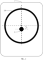
FIG. 3 is a schematic diagram of an image capturing window of a palm recognition device according to an embodiment of the present disclosure. -
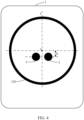
FIG. 4 is a schematic diagram of an image capturing window of a palm recognition device according to an embodiment of the present disclosure. -
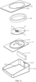
FIG. 5 is an exploded view of a palm recognition device according to an embodiment of the present disclosure. -
FIG. 6 is an exploded view of a palm recognition device according to an embodiment of the present disclosure. -
- 1: housing, 11: bottom housing, 110: accommodating cavity, 111: speaker hole, 12: panel, 120: image capturing window, o: central point, and I: central axis;
- 2: PCB;
- 3: camera;
- 4: light component, 41: light-emitting member, and 42: light guide ring;
- 5: speaker; and
- 6: wire.
- To make the objectives, technical solutions, and advantages of the present disclosure clearer, the following further describes implementations of the present disclosure in detail with reference to the accompanying drawings.
- Terms used in the implementations of the present disclosure are merely used to explain embodiments of the present disclosure, and are not intended to limit the present disclosure. Unless otherwise defined, the technical terms or scientific terms used in the implementations of the present disclosure are to have general meanings understood by a person of ordinary skill in the field of the present disclosure. "One", "a", or similar terms used in the specification of the present disclosure and claims do not indicate a quantity limitation, but indicate that there is at least one. "Comprise", "include", or similar terms mean that elements or articles appearing before "comprise" or "include" cover listed elements or articles appearing after "comprise" or "include" and equivalents thereof, and do not exclude other elements or articles. "Connection", "connected", or similar terms are not limited to a physical or mechanical connection, but may include an electrical connection, regardless of a direct or indirect connection. "Up", "down", "left", "right", and the like are merely used for indicating relative positional relationships. After absolute positions of described objects change, relative positional relationships may also change. "A plurality of" means two or more, unless otherwise definitely limited.
- A palm recognition device is a device that captures a palm image by a camera, and recognizes the palm image. For the palm recognition device, improving quality of the palm image captured by the palm recognition device is a precondition of improving a recognition speed and recognition accuracy of the palm recognition device.
- In the embodiments of the present disclosure including the embodiments of both the claims and the specification (hereinafter referred to as "all embodiments of the present disclosure"), as shown in
FIG. 1 , when a user aligns an actual central point B of the palm with a camera of the palm recognition device, the quality of the palm image captured by the palm recognition device is relative high. During palm recognition, the user generally considers a point A as a central point of the palm, and aligns the point A with a central point of an image capturing window of the palm recognition device. - Cameras of palm recognition devices in the related art all face central points of image capturing windows. Therefore, palm images captured by these palm recognition devices are all palm images captured when cameras directly face points A of the palms. Quality of the palm images are relatively low, affecting the recognition speed and recognition accuracy of the palm recognition devices, so that during use of the palm recognition device, the user feels the recognition is insensitive, and needs to move the palm up and down for recognition.
- In view of the foregoing technical problem, the embodiments of the present disclosure provide a palm recognition device. Quality of a palm image captured by the palm recognition device is relative high, and helps improve a recognition speed and recognition accuracy of the palm recognition device.
- The palm recognition device provided in the embodiments of the present disclosure is described below.
- As shown in
FIG. 2 ,FIG. 5 , andFIG. 6 , the palm recognition device includes ahousing 1, a printed circuit board (PCB) 2, and acamera 3. Thehousing 1 has a transparentimage capturing window 120. ThePCB 2 is coupled to thecamera 3, and thePCB 2 and thecamera 3 are both located inside thehousing 1. Thecamera 3 faces toward theimage capturing window 120, and a projection of thecamera 3 on theimage capturing window 120 is offset relative to a central point o of theimage capturing window 120. For example, a central point of the projection of thecamera 3 on theimage capturing window 120 is offset relative to the central point o of theimage capturing window 120. - A specific application of the palm recognition device is not limited in this embodiment of the present disclosure. In all embodiments of the present disclosure, the palm recognition device is used for payment, and in some other examples, the palm recognition device is used as a part of door control.
- The
housing 1 is a structural member of the palm recognition device, and is configured to support and fix other components of the palm recognition device. - The PCB 2 is equipped with a processor, a chip, an interface, and other electronic modules. The PCB 2 can recognize the palm image captured by the
camera 3, and can control thecamera 3. - The
camera 3 is configured to capture the palm image. A type of thecamera 3 is not limited in this embodiment of the present disclosure. In all embodiments of the present disclosure, thecamera 3 includes at least one of a two-dimensional camera and a three-dimensional camera. In addition, thecamera 3 may further include at least one of an infrared light module and a depth map module, to improve quality of the palm image captured by thecamera 3. - The projection of the
camera 3 on theimage capturing window 120 is a projection along a direction of a central axis of thecamera 3. The central axis of thecamera 3 is a principal optical axis of thecamera 3. That a projection of thecamera 3 on theimage capturing window 120 is offset relative to a central point o of theimage capturing window 120 may alternatively be understood as that an intersection point between the principal optical axis of thecamera 3 and theimage capturing window 120 is offset relative to the central point o of theimage capturing window 120. In all embodiments of the present disclosure, a central point of the projection of thecamera 3 on theimage capturing window 120 is offset, along a central axis I of theimage capturing window 120, relative to the central point o of theimage capturing window 120. - According to the technical solution provided in the embodiments of the present disclosure, a central point of the projection of the
camera 3 on theimage capturing window 120 is offset relative to the central point o of theimage capturing window 120, so that when the user aligns a point A of the palm with the central point o of theimage capturing window 120, a point that thecamera 3 directly faces on the palm is located below the point A, for example, a point B or a point between the point A and the point B. Therefore, the quality of the palm image captured by the palm recognition device is relative high, which helps to improve the recognition speed and the recognition accuracy of the palm recognition device. In addition, using the palm recognition device provided in this embodiment of the present disclosure, the user does not need to change an existing habit of palm recognition. - A shooting field of view of the
camera 3 is conical and radial, and therefore, in actual use, even if thecamera 3 does not directly face the point B, the palm image with relative high quality can be obtained. - In some examples, h is less than H. That is, a point that the
camera 3 directly faces is located between the point A and the point B. - In this way, for some users that know an actual central point of the palm is the point B, when the users align the point B with the central point o of the
image capturing window 120, a point that thecamera 3 directly faces on the palm does not excessively deviate relative to the point B toward a direction away from the point A, and possibility of capturing a palm image with relative low quality is reduced. - A distance between a central point of the projection and the central point o in this embodiment of the present disclosure is not limited. In some examples, as shown in
FIG. 3 andFIG. 4 , a distance h between a central point of the projection of thecamera 3 on theimage capturing window 120 and the central point o, in particular along a direction of a central axis I of theimage capturing window 120, is greater than or equal to 5 mm, and less than or equal to 25 mm. By setting 5 mm ≤h≤ 25 mm, that h is less than H can be implemented. That is, by setting 5 mm ≤h≤ 25 mm, when the palm recognition device recognizes the palms of the users that consider the point A as the central point of the palm and that consider the point B as the central point of the palm, the palm images with relative high quality can be obtained. - The distance between a central point of the projection of the
camera 3 on theimage capturing window 120 and the central point o is equal to a distance between the intersection point, between the principal optical axis of thecamera 3 and theimage capturing window 120, and the central point o of theimage capturing window 120, in particular along a direction of a central axis I of theimage capturing window 120. - A quantity of the
cameras 3 is not limited in this embodiment of the present disclosure. In some examples, as shown inFIG. 2 andFIG. 3 , there is onecamera 3, and the projection of thecamera 3 on theimage capturing window 120 is located on a central axis I of the image capturing window 120.When the plane of theimage capturing window 120 is vertical, the central axis I is in a vertical direction. - In some other examples, as shown in
FIG. 4 , there are twocameras 3, and the projections of the twocameras 3 on theimage capturing window 120 are symmetrical with respective to the central axis I of theimage capturing window 120. - A form of the
image capturing window 120 is not limited in this embodiment of the present disclosure. In some examples, as shown inFIG. 2 to FIG. 4 , theimage capturing window 120 is circular. Certainly, theimage capturing window 120 may alternatively be elliptical, rectangular, or the like. - The
housing 1 is described in more detail below by using examples. - In some examples, as shown in
FIG. 2 ,FIG. 5 , andFIG. 6 , thehousing 1 includes thebottom housing 11 and thepanel 12. Thebottom housing 11 includes anaccommodating cavity 110. Thepanel 12 seals an opening of theaccommodating cavity 110, and thepanel 12 has theimage capturing window 120. - The
panel 12 seals theaccommodating cavity 110 of thebottom housing 11, to protect a device in theaccommodating cavity 110. A type of thepanel 12 is not limited in this embodiment of the present disclosure. In some examples, thepanel 12 has a touch function, and is coupled to (e.g., electrically connected to) thePCB 2, so that the user can send an instruction to the palm recognition device by touching thepanel 12. In some other examples, thepanel 12 may alternatively not have the touch function. A material of thepanel 12 is not limited in this embodiment of the present disclosure. In some examples, thepanel 12 is a glass panel. - An application scenario of the palm recognition device is not limited in this embodiment of the present disclosure. In some examples, as shown in
FIG. 2 , the palm recognition device is a tabletop device to be placed on a tabletop or other support surfaces for use. In this case, thepanel 12 may be arranged inclined relative to a horizontal plane. - In some other examples, the palm recognition device may alternatively be a wall-mounted device to be hung on a wall for use. In this case, the
panel 12 may be arranged vertically. - To improve interaction experience between the user and the palm recognition device, in some examples, as shown in
FIG. 2 , the palm recognition device further includes alight component 4. Thelight component 4 is located inside thehousing 1, and surrounds thecamera 3, and thelight component 4 faces theimage capturing window 120. - According to the technical solution provided in this embodiment of the present disclosure, by arranging the
light component 4, the palm recognition device can transmit information to the user through thelight component 4. - For example, when the palm recognition device is used for payment, the
light component 4 transmits information about the payment to the user. For example, when the user successfully pays, thelight component 4 emits green light to represent successful payment. - In some examples, as shown in
FIG. 2 , thelight component 4 is ring-shaped, for example, circular ring-shaped or square ring-shaped. For example, thelight component 4 is circular ring-shaped, and has a same central point with theimage capturing window 120. - In this way, when the
light component 4 emits light, a light circle around thecamera 3 is formed, and the palm recognition device is more beautiful. - In some examples, the
light component 4 can emit light of a plurality of colors, and light of different colors can transmit different information. For example, green light represents that the payment succeeds, and red light represents that the payment fails. - In some examples, the
light component 4 has a plurality of light emitting forms, for example, flashing light and constant light, and different light emitting forms can transmit different information. - An implementation of the
light component 4 is described below by using examples. - In some examples, as shown in
FIG. 5 andFIG. 6 , thelight component 4 includes a light-emittingmember 41 and alight guide ring 42. The light-emittingmember 41 is fixed on thePCB 2, and is coupled to thePCB 2. Thelight guide ring 42 surrounds thecamera 3, and is located between theimage capturing window 120 and the light-emittingmember 41. - In some examples, the light-emitting
member 41 can emit light of a plurality of colors. - A principle in which the light-emitting
member 41 can emit the light of a plurality of colors is not limited in this embodiment of the present disclosure. In some examples, a lamp bead of the light-emittingmember 41 may be a variable color lamp bead. A principle of the variable color lamp bead is not limited in this embodiment of the present disclosure. In some examples, the variable color lamp bead can change a color of the light according to magnitude of a current. In some other examples, the variable color lamp bead includes three sub-lamp beads that are separately red, green, and blue, and the variable color lamp bead can control lighting and extinguishing of the three sub-lamp beads to emit the light of a plurality of colors. - A form of the light-emitting
member 41 is not limited in this embodiment of the present disclosure. In some examples, the light-emittingmember 41 is a ring-shaped lamp. In some other examples, the light-emittingmember 41 has a plurality of lamp beads, and the plurality of lamp beads are arranged in a shape of a circular ring. - The
light guide ring 42 is configured to uniformly disperse the light emitted by the light-emittingmember 41, so that brightness of the formed light circle is uniform. - In some examples, as shown in
FIG. 5 andFIG. 6 , the palm recognition device further includes aspeaker 5. Thespeaker 5 is located inside thehousing 1, and is coupled to thePCB 2. - The
speaker 5 may be equipped with one or more speaker devices. - According to the technical solution provided in this embodiment of the present disclosure, by arranging the
speaker 5, the palm recognition device can further transmit information to the user. For example, when the user successfully pays, thespeaker 5 produces a prompt tone that the payment has succeeded. - In some examples, as shown in
FIG. 5 andFIG. 6 , thebottom housing 11 has aspeaker hole 111, and thespeaker hole 111 faces thespeaker 5. This helps the sound produced by thespeaker 5 penetrate thebottom housing 11 and be transmitted toward outside. - In some examples, as shown in
FIG. 2 , the palm recognition device further includes awire 6. An end of thewire 6 extends into an interior of thehousing 1, and is coupled to thePCB 2, and an other end is configured to be coupled to an external power supply. - In some examples, the palm recognition device does not have a battery inside, and the
wire 6 needs to be connected to a power supply for the palm recognition device to be normally used. In this case, thewire 6 may be connected to thehousing 1 non-detachably. - In some other examples, the palm recognition device has a battery inside, and when the battery has power, the
wire 6 is not connected to a power supply, and the palm recognition device can be normally used. In this case, thewire 6 may be detachably connected to thehousing 1 and thePCB 2, and both ends of thewire 6 have a plug. - The foregoing descriptions are embodiments of the present disclosure, but are not intended to limit the present disclosure. Any modification, equivalent replacement, or improvement made within the principle of the present disclosure shall fall within the protection scope of the present disclosure.
Claims (10)
- A palm recognition device, comprising a housing (1), a printed circuit board (PCB) (2), and a camera (3),the housing (1) having a transparent image capturing window (120);the PCB (2) being coupled to the camera (3), and the PCB (2) and the camera (3) both being located inside the housing (1); andthe camera (3) facing towards the image capturing window (120), a projection of the camera (3) on the image capturing window (120) being offset relative to a central point (o) of the image capturing window (120).
- The palm recognition device according to claim 1, wherein a distance between a central point of the projection of the camera (3) on the image capturing window (120) and the central point (o) of the image capturing window (120), in particular along a direction of a central axis (I) of the image capturing window (120), is greater than or equal to 5 mm, and less than or equal to 25 mm.
- The palm recognition device according to claim 1 or 2, wherein there is one camera (3), and a central point of a projection of the one camera (3) on the image capturing window (120) is located on a central axis (I) of the image capturing window (120).
- The palm recognition device according to claim 1 or 2, wherein there are two cameras (3), and projections of the two cameras (3) on the image capturing window (120) are symmetrical with respective to a central axis (I) of the image capturing window (120).
- The palm recognition device according to claim 1 or 2, wherein the image capturing window (120) is circular.
- The palm recognition device according to claim 1 or 2, wherein the housing (1) comprises a bottom housing (11) and a panel (12),the bottom housing (11) comprising an accommodating cavity (110); andthe panel (12) sealing an opening of the accommodating cavity (110), and the panel (12) having the image capturing window (120).
- The palm recognition device according to claim 6, wherein the panel (12) is arranged inclined relative to a horizontal plane.
- The palm recognition device according to claim 1 or 2, wherein the palm recognition device further comprises a light component (4),
the light component (4) being located inside the housing (1), and surrounding the camera (3), the light component (4) being opposite to the image capturing window (120). - The palm recognition device according to claim 8, wherein the light component (4) comprises a light-emitting member (41) and a light guide ring (42),the light-emitting member (41) being fixed on the PCB (2), and being coupled to the PCB (2); andthe light guide ring (42) surrounding the camera (3), and being located between the image capturing window (120) and the light-emitting member (41).
- The palm recognition device according to claim 1 or 2, further comprising a speaker (5), the speaker (5) being located inside the housing (1), and being coupled to the PCB (2).
Applications Claiming Priority (2)
| Application Number | Priority Date | Filing Date | Title |
|---|---|---|---|
| CN202220658952.2U CN217061035U (en) | 2022-03-24 | 2022-03-24 | Brush palm device |
| PCT/CN2023/079841 WO2023179347A1 (en) | 2022-03-24 | 2023-03-06 | Palm-swiping device |
Publications (2)
| Publication Number | Publication Date |
|---|---|
| EP4471736A1 true EP4471736A1 (en) | 2024-12-04 |
| EP4471736A4 EP4471736A4 (en) | 2025-04-30 |
Family
ID=82466091
Family Applications (1)
| Application Number | Title | Priority Date | Filing Date |
|---|---|---|---|
| EP23773598.0A Pending EP4471736A4 (en) | 2022-03-24 | 2023-03-06 | Palm-swiping device |
Country Status (5)
| Country | Link |
|---|---|
| US (2) | US12475732B2 (en) |
| EP (1) | EP4471736A4 (en) |
| JP (1) | JP2025507197A (en) |
| CN (1) | CN217061035U (en) |
| WO (1) | WO2023179347A1 (en) |
Families Citing this family (1)
| Publication number | Priority date | Publication date | Assignee | Title |
|---|---|---|---|---|
| CN217061035U (en) | 2022-03-24 | 2022-07-26 | 腾讯科技(深圳)有限公司 | Brush palm device |
Family Cites Families (39)
| Publication number | Priority date | Publication date | Assignee | Title |
|---|---|---|---|---|
| US5335288A (en) * | 1992-02-10 | 1994-08-02 | Faulkner Keith W | Apparatus and method for biometric identification |
| HK1062117A2 (en) * | 2002-09-25 | 2004-09-17 | The Hong Kong Polytechnic University | Method of palm print identification using geometry, line and/or texture features |
| JP4546169B2 (en) * | 2004-06-28 | 2010-09-15 | 富士通株式会社 | An imaging device for palm authentication |
| CN1586395A (en) * | 2004-09-10 | 2005-03-02 | 清华大学 | In vivo palm angiography image acquisition instrument |
| KR20060093444A (en) * | 2005-02-21 | 2006-08-25 | (주)링스텔레콤 | Personal recognition device using hand vein pattern |
| JP2007334659A (en) * | 2006-06-15 | 2007-12-27 | Oki Electric Ind Co Ltd | Individual authentication system |
| JP4640295B2 (en) * | 2006-09-07 | 2011-03-02 | 株式会社日立製作所 | Personal authentication apparatus and method |
| JP4957514B2 (en) * | 2007-11-12 | 2012-06-20 | 富士通株式会社 | GUIDE DEVICE, IMAGING DEVICE, IMAGING SYSTEM, GUIDING METHOD |
| JP4665997B2 (en) * | 2008-05-12 | 2011-04-06 | 日本電気株式会社 | Biological pattern imaging apparatus, biological pattern imaging method, biological pattern imaging program |
| KR101109237B1 (en) * | 2009-09-16 | 2012-01-30 | 삼성전기주식회사 | Biometric device |
| US20110292212A1 (en) * | 2010-05-27 | 2011-12-01 | Asmo Co., Ltd. | Washer nozzle for vehicle mounted camera, vehicle mounted camera, and washer device for vehicle |
| US20120014569A1 (en) * | 2010-07-16 | 2012-01-19 | Ib Korea Ltd. | Method and apparatus for slim type fingerprint recognition device |
| WO2012011181A1 (en) * | 2010-07-22 | 2012-01-26 | 富士通株式会社 | Vein image capturing device |
| CN102402679A (en) * | 2010-09-07 | 2012-04-04 | 北京北科慧识科技股份有限公司 | Non-contact type palm print and palm vein recognition system |
| WO2014115682A1 (en) * | 2013-01-23 | 2014-07-31 | 合同会社3Dragons | Personal authentication device |
| EP2982301A4 (en) * | 2013-04-01 | 2016-11-23 | Fujitsu Frontech Ltd | Palm vein image capture device |
| WO2017076292A1 (en) * | 2015-11-02 | 2017-05-11 | Shenzhen Huiding Technology Co., Ltd. | Multifunction fingerprint sensor having optical sensing against fingerprint spoofing |
| US10588178B1 (en) * | 2015-06-25 | 2020-03-10 | Amazon Technologies, Inc. | Window heater system |
| JP2018189369A (en) * | 2015-09-28 | 2018-11-29 | 株式会社ドリーム・ジーピー | Three-dimensional measurement apparatus |
| EP3392824A4 (en) * | 2015-12-18 | 2019-10-23 | Hitachi, Ltd. | DEVICE AND SYSTEM FOR BIOMETRIC AUTHENTICATION |
| US10303865B2 (en) * | 2016-08-31 | 2019-05-28 | Redrock Biometrics, Inc. | Blue/violet light touchless palm print identification |
| JP6872349B2 (en) * | 2016-11-11 | 2021-05-19 | 株式会社日立製作所 | Blood vessel imaging device and personal authentication system |
| KR101892184B1 (en) * | 2017-02-14 | 2018-08-29 | 크루셜텍(주) | Multi biometric terminal and access control system having the same |
| KR101802359B1 (en) * | 2017-05-30 | 2017-11-29 | 주식회사 올아이티탑 | Electronic payment system using vein recognition and method for processing thereof |
| KR102185854B1 (en) * | 2017-09-09 | 2020-12-02 | 애플 인크. | Implementation of biometric authentication |
| JP6846330B2 (en) * | 2017-11-27 | 2021-03-24 | 株式会社日立製作所 | Biometric device and biometric system |
| US10872221B2 (en) * | 2018-06-21 | 2020-12-22 | Amazon Technologies, Inc | Non-contact biometric identification system |
| US11126814B2 (en) * | 2018-10-17 | 2021-09-21 | Qualcomm Incorporated | Ultrasonic fingerprint sensor with flexible substrate |
| CN109176562A (en) * | 2018-11-16 | 2019-01-11 | 荆门它山之石电子科技有限公司 | A kind of domestic robot and its security system |
| CN109614782A (en) * | 2018-11-16 | 2019-04-12 | 荆门它山之石电子科技有限公司 | A kind of computer logins device and its accessing system |
| US10891458B2 (en) * | 2019-02-28 | 2021-01-12 | Qualcomm Incorporated | Module architecture for large area ultrasonic fingerprint sensor |
| US20220285461A1 (en) * | 2019-08-08 | 2022-09-08 | Semiconductor Energy Laboratory Co., Ltd. | Display Device and Electronic Device |
| CN111881719B (en) * | 2020-06-09 | 2024-04-16 | 青岛奥美克生物信息科技有限公司 | Non-contact type biological recognition guiding device, method and biological feature recognition system |
| CN213069856U (en) * | 2020-10-19 | 2021-04-27 | 上海鹰捷智能科技有限公司 | Palm print recognition equipment |
| CN112232304B (en) * | 2020-11-18 | 2024-10-29 | 深圳市坶坭普电子科技有限公司 | Non-contact type finger/palm print acquisition device and method |
| CN215341168U (en) * | 2021-07-28 | 2021-12-28 | 腾讯科技(深圳)有限公司 | Scanning device and payment device |
| CN215729879U (en) * | 2021-08-31 | 2022-02-01 | 腾讯科技(深圳)有限公司 | Identification device and payment device |
| CN114067377A (en) * | 2021-09-26 | 2022-02-18 | 盛视科技股份有限公司 | Multispectral palm vein image acquisition module, device and method |
| CN217061035U (en) * | 2022-03-24 | 2022-07-26 | 腾讯科技(深圳)有限公司 | Brush palm device |
-
2022
- 2022-03-24 CN CN202220658952.2U patent/CN217061035U/en active Active
-
2023
- 2023-03-06 EP EP23773598.0A patent/EP4471736A4/en active Pending
- 2023-03-06 JP JP2024554934A patent/JP2025507197A/en active Pending
- 2023-03-06 WO PCT/CN2023/079841 patent/WO2023179347A1/en not_active Ceased
- 2023-10-09 US US18/378,061 patent/US12475732B2/en active Active
-
2025
- 2025-10-27 US US19/370,487 patent/US20260051195A1/en active Pending
Also Published As
| Publication number | Publication date |
|---|---|
| US20240037978A1 (en) | 2024-02-01 |
| JP2025507197A (en) | 2025-03-13 |
| EP4471736A4 (en) | 2025-04-30 |
| WO2023179347A1 (en) | 2023-09-28 |
| CN217061035U (en) | 2022-07-26 |
| US12475732B2 (en) | 2025-11-18 |
| US20260051195A1 (en) | 2026-02-19 |
Similar Documents
| Publication | Publication Date | Title |
|---|---|---|
| US20260051195A1 (en) | Palm recognition device | |
| US9465480B2 (en) | Position detection apparatus, adjustment method, and adjustment program | |
| CN109803078A (en) | a terminal device | |
| JP2015158887A (en) | Position detection system, and control method of position detection system | |
| JP2012252091A5 (en) | ||
| JP2015159524A (en) | Projector, display device, and control method of projector | |
| CN107911554A (en) | Electronic device and method for controlling the electronic device | |
| CN109348012A (en) | Electronic device, control method thereof and control device thereof | |
| JP2015158885A (en) | Position detection device, projector, position detection system, and control method of position detection device | |
| CN209170443U (en) | Electronic equipment | |
| CN116068756A (en) | Display device and head-mounted display equipment suitable for eye movement tracking | |
| JP5969643B1 (en) | Method for enhancing connector visibility, connector access system and portable computer | |
| CN107121883A (en) | One kind projection and lighting device | |
| CN208819500U (en) | Sand table device | |
| CN105657187A (en) | Visible light communication method and system and equipment | |
| CN111131554A (en) | Terminal device | |
| CN213276698U (en) | a translation pen | |
| CN207049694U (en) | Light-emitting device and mobile terminal | |
| CN216697249U (en) | Interactive device | |
| CN109318628A (en) | A kind of Art Design drawing special intelligent drawing pen | |
| CN211956946U (en) | Backlight module, display module and display device | |
| CN218273427U (en) | Interaction module and interaction equipment | |
| CN218956996U (en) | Wrist strap type equipment | |
| CN107479250B (en) | Light-emitting device and electronic equipment | |
| CN218886549U (en) | Head Mounted Devices and Handle Components |
Legal Events
| Date | Code | Title | Description |
|---|---|---|---|
| STAA | Information on the status of an ep patent application or granted ep patent |
Free format text: STATUS: THE INTERNATIONAL PUBLICATION HAS BEEN MADE |
|
| PUAI | Public reference made under article 153(3) epc to a published international application that has entered the european phase |
Free format text: ORIGINAL CODE: 0009012 |
|
| STAA | Information on the status of an ep patent application or granted ep patent |
Free format text: STATUS: REQUEST FOR EXAMINATION WAS MADE |
|
| 17P | Request for examination filed |
Effective date: 20240826 |
|
| AK | Designated contracting states |
Kind code of ref document: A1 Designated state(s): AL AT BE BG CH CY CZ DE DK EE ES FI FR GB GR HR HU IE IS IT LI LT LU LV MC ME MK MT NL NO PL PT RO RS SE SI SK SM TR |
|
| A4 | Supplementary search report drawn up and despatched |
Effective date: 20250327 |
|
| RIC1 | Information provided on ipc code assigned before grant |
Ipc: G06V 40/13 20220101AFI20250321BHEP |
|
| DAV | Request for validation of the european patent (deleted) | ||
| DAX | Request for extension of the european patent (deleted) |