EP4471394A1 - Safety mat, mold clamping device, and injection molding machine - Google Patents
Safety mat, mold clamping device, and injection molding machine Download PDFInfo
- Publication number
- EP4471394A1 EP4471394A1 EP23746635.4A EP23746635A EP4471394A1 EP 4471394 A1 EP4471394 A1 EP 4471394A1 EP 23746635 A EP23746635 A EP 23746635A EP 4471394 A1 EP4471394 A1 EP 4471394A1
- Authority
- EP
- European Patent Office
- Prior art keywords
- pressure
- mat
- sensitive switch
- mold clamping
- step board
- Prior art date
- Legal status (The legal status is an assumption and is not a legal conclusion. Google has not performed a legal analysis and makes no representation as to the accuracy of the status listed.)
- Pending
Links
Images
Classifications
-
- B—PERFORMING OPERATIONS; TRANSPORTING
- B29—WORKING OF PLASTICS; WORKING OF SUBSTANCES IN A PLASTIC STATE IN GENERAL
- B29C—SHAPING OR JOINING OF PLASTICS; SHAPING OF MATERIAL IN A PLASTIC STATE, NOT OTHERWISE PROVIDED FOR; AFTER-TREATMENT OF THE SHAPED PRODUCTS, e.g. REPAIRING
- B29C45/00—Injection moulding, i.e. forcing the required volume of moulding material through a nozzle into a closed mould; Apparatus therefor
- B29C45/17—Component parts, details or accessories; Auxiliary operations
- B29C45/84—Safety devices
-
- B—PERFORMING OPERATIONS; TRANSPORTING
- B29—WORKING OF PLASTICS; WORKING OF SUBSTANCES IN A PLASTIC STATE IN GENERAL
- B29C—SHAPING OR JOINING OF PLASTICS; SHAPING OF MATERIAL IN A PLASTIC STATE, NOT OTHERWISE PROVIDED FOR; AFTER-TREATMENT OF THE SHAPED PRODUCTS, e.g. REPAIRING
- B29C45/00—Injection moulding, i.e. forcing the required volume of moulding material through a nozzle into a closed mould; Apparatus therefor
- B29C45/17—Component parts, details or accessories; Auxiliary operations
- B29C45/64—Mould opening, closing or clamping devices
-
- B—PERFORMING OPERATIONS; TRANSPORTING
- B29—WORKING OF PLASTICS; WORKING OF SUBSTANCES IN A PLASTIC STATE IN GENERAL
- B29C—SHAPING OR JOINING OF PLASTICS; SHAPING OF MATERIAL IN A PLASTIC STATE, NOT OTHERWISE PROVIDED FOR; AFTER-TREATMENT OF THE SHAPED PRODUCTS, e.g. REPAIRING
- B29C45/00—Injection moulding, i.e. forcing the required volume of moulding material through a nozzle into a closed mould; Apparatus therefor
- B29C45/17—Component parts, details or accessories; Auxiliary operations
- B29C45/76—Measuring, controlling or regulating
- B29C45/7653—Measuring, controlling or regulating mould clamping forces
-
- F—MECHANICAL ENGINEERING; LIGHTING; HEATING; WEAPONS; BLASTING
- F16—ENGINEERING ELEMENTS AND UNITS; GENERAL MEASURES FOR PRODUCING AND MAINTAINING EFFECTIVE FUNCTIONING OF MACHINES OR INSTALLATIONS; THERMAL INSULATION IN GENERAL
- F16P—SAFETY DEVICES IN GENERAL; SAFETY DEVICES FOR PRESSES
- F16P3/00—Safety devices acting in conjunction with the control or operation of a machine; Control arrangements requiring the simultaneous use of two or more parts of the body
- F16P3/12—Safety devices acting in conjunction with the control or operation of a machine; Control arrangements requiring the simultaneous use of two or more parts of the body with means, e.g. feelers, which in case of the presence of a body part of a person in or near the danger zone influence the control or operation of the machine
-
- G—PHYSICS
- G01—MEASURING; TESTING
- G01L—MEASURING FORCE, STRESS, TORQUE, WORK, MECHANICAL POWER, MECHANICAL EFFICIENCY, OR FLUID PRESSURE
- G01L1/00—Measuring force or stress, in general
- G01L1/20—Measuring force or stress, in general by measuring variations in ohmic resistance of solid materials or of electrically-conductive fluids; by making use of electrokinetic cells, i.e. liquid-containing cells wherein an electrical potential is produced or varied upon the application of stress
- G01L1/205—Measuring force or stress, in general by measuring variations in ohmic resistance of solid materials or of electrically-conductive fluids; by making use of electrokinetic cells, i.e. liquid-containing cells wherein an electrical potential is produced or varied upon the application of stress using distributed sensing elements
-
- G—PHYSICS
- G01—MEASURING; TESTING
- G01L—MEASURING FORCE, STRESS, TORQUE, WORK, MECHANICAL POWER, MECHANICAL EFFICIENCY, OR FLUID PRESSURE
- G01L5/00—Apparatus for, or methods of, measuring force, work, mechanical power, or torque, specially adapted for specific purposes
- G01L5/0028—Force sensors associated with force applying means
- G01L5/0038—Force sensors associated with force applying means applying a pushing force
-
- H—ELECTRICITY
- H01—ELECTRIC ELEMENTS
- H01H—ELECTRIC SWITCHES; RELAYS; SELECTORS; EMERGENCY PROTECTIVE DEVICES
- H01H1/00—Contacts
- H01H1/02—Contacts characterised by the material thereof
- H01H1/021—Composite material
- H01H1/029—Composite material comprising conducting material dispersed in an elastic support or binding material
-
- H—ELECTRICITY
- H01—ELECTRIC ELEMENTS
- H01H—ELECTRIC SWITCHES; RELAYS; SELECTORS; EMERGENCY PROTECTIVE DEVICES
- H01H3/00—Mechanisms for operating contacts
- H01H3/02—Operating parts, i.e. for operating driving mechanism by a mechanical force external to the switch
- H01H3/14—Operating parts, i.e. for operating driving mechanism by a mechanical force external to the switch adapted for operation by a part of the human body other than the hand, e.g. by foot
- H01H3/141—Cushion or mat switches
-
- B—PERFORMING OPERATIONS; TRANSPORTING
- B29—WORKING OF PLASTICS; WORKING OF SUBSTANCES IN A PLASTIC STATE IN GENERAL
- B29C—SHAPING OR JOINING OF PLASTICS; SHAPING OF MATERIAL IN A PLASTIC STATE, NOT OTHERWISE PROVIDED FOR; AFTER-TREATMENT OF THE SHAPED PRODUCTS, e.g. REPAIRING
- B29C2945/00—Indexing scheme relating to injection moulding, i.e. forcing the required volume of moulding material through a nozzle into a closed mould
- B29C2945/76—Measuring, controlling or regulating
- B29C2945/76003—Measured parameter
- B29C2945/76006—Pressure
-
- B—PERFORMING OPERATIONS; TRANSPORTING
- B29—WORKING OF PLASTICS; WORKING OF SUBSTANCES IN A PLASTIC STATE IN GENERAL
- B29C—SHAPING OR JOINING OF PLASTICS; SHAPING OF MATERIAL IN A PLASTIC STATE, NOT OTHERWISE PROVIDED FOR; AFTER-TREATMENT OF THE SHAPED PRODUCTS, e.g. REPAIRING
- B29C2945/00—Indexing scheme relating to injection moulding, i.e. forcing the required volume of moulding material through a nozzle into a closed mould
- B29C2945/76—Measuring, controlling or regulating
- B29C2945/76003—Measured parameter
- B29C2945/76167—Presence, absence of objects
-
- B—PERFORMING OPERATIONS; TRANSPORTING
- B29—WORKING OF PLASTICS; WORKING OF SUBSTANCES IN A PLASTIC STATE IN GENERAL
- B29C—SHAPING OR JOINING OF PLASTICS; SHAPING OF MATERIAL IN A PLASTIC STATE, NOT OTHERWISE PROVIDED FOR; AFTER-TREATMENT OF THE SHAPED PRODUCTS, e.g. REPAIRING
- B29C2945/00—Indexing scheme relating to injection moulding, i.e. forcing the required volume of moulding material through a nozzle into a closed mould
- B29C2945/76—Measuring, controlling or regulating
- B29C2945/76177—Location of measurement
- B29C2945/76224—Closure or clamping unit
-
- B—PERFORMING OPERATIONS; TRANSPORTING
- B29—WORKING OF PLASTICS; WORKING OF SUBSTANCES IN A PLASTIC STATE IN GENERAL
- B29C—SHAPING OR JOINING OF PLASTICS; SHAPING OF MATERIAL IN A PLASTIC STATE, NOT OTHERWISE PROVIDED FOR; AFTER-TREATMENT OF THE SHAPED PRODUCTS, e.g. REPAIRING
- B29C2945/00—Indexing scheme relating to injection moulding, i.e. forcing the required volume of moulding material through a nozzle into a closed mould
- B29C2945/76—Measuring, controlling or regulating
- B29C2945/76177—Location of measurement
- B29C2945/76224—Closure or clamping unit
- B29C2945/76227—Closure or clamping unit mould platen
-
- B—PERFORMING OPERATIONS; TRANSPORTING
- B29—WORKING OF PLASTICS; WORKING OF SUBSTANCES IN A PLASTIC STATE IN GENERAL
- B29C—SHAPING OR JOINING OF PLASTICS; SHAPING OF MATERIAL IN A PLASTIC STATE, NOT OTHERWISE PROVIDED FOR; AFTER-TREATMENT OF THE SHAPED PRODUCTS, e.g. REPAIRING
- B29C2945/00—Indexing scheme relating to injection moulding, i.e. forcing the required volume of moulding material through a nozzle into a closed mould
- B29C2945/76—Measuring, controlling or regulating
- B29C2945/76344—Phase or stage of measurement
- B29C2945/76387—Mould closing
-
- B—PERFORMING OPERATIONS; TRANSPORTING
- B29—WORKING OF PLASTICS; WORKING OF SUBSTANCES IN A PLASTIC STATE IN GENERAL
- B29C—SHAPING OR JOINING OF PLASTICS; SHAPING OF MATERIAL IN A PLASTIC STATE, NOT OTHERWISE PROVIDED FOR; AFTER-TREATMENT OF THE SHAPED PRODUCTS, e.g. REPAIRING
- B29C2945/00—Indexing scheme relating to injection moulding, i.e. forcing the required volume of moulding material through a nozzle into a closed mould
- B29C2945/76—Measuring, controlling or regulating
- B29C2945/76344—Phase or stage of measurement
- B29C2945/76394—Mould opening
-
- B—PERFORMING OPERATIONS; TRANSPORTING
- B29—WORKING OF PLASTICS; WORKING OF SUBSTANCES IN A PLASTIC STATE IN GENERAL
- B29C—SHAPING OR JOINING OF PLASTICS; SHAPING OF MATERIAL IN A PLASTIC STATE, NOT OTHERWISE PROVIDED FOR; AFTER-TREATMENT OF THE SHAPED PRODUCTS, e.g. REPAIRING
- B29C2945/00—Indexing scheme relating to injection moulding, i.e. forcing the required volume of moulding material through a nozzle into a closed mould
- B29C2945/76—Measuring, controlling or regulating
- B29C2945/76494—Controlled parameter
- B29C2945/76568—Position
-
- B—PERFORMING OPERATIONS; TRANSPORTING
- B29—WORKING OF PLASTICS; WORKING OF SUBSTANCES IN A PLASTIC STATE IN GENERAL
- B29C—SHAPING OR JOINING OF PLASTICS; SHAPING OF MATERIAL IN A PLASTIC STATE, NOT OTHERWISE PROVIDED FOR; AFTER-TREATMENT OF THE SHAPED PRODUCTS, e.g. REPAIRING
- B29C2945/00—Indexing scheme relating to injection moulding, i.e. forcing the required volume of moulding material through a nozzle into a closed mould
- B29C2945/76—Measuring, controlling or regulating
- B29C2945/76655—Location of control
- B29C2945/76702—Closure or clamping device
- B29C2945/76705—Closure or clamping device mould platen
-
- B—PERFORMING OPERATIONS; TRANSPORTING
- B29—WORKING OF PLASTICS; WORKING OF SUBSTANCES IN A PLASTIC STATE IN GENERAL
- B29C—SHAPING OR JOINING OF PLASTICS; SHAPING OF MATERIAL IN A PLASTIC STATE, NOT OTHERWISE PROVIDED FOR; AFTER-TREATMENT OF THE SHAPED PRODUCTS, e.g. REPAIRING
- B29C2945/00—Indexing scheme relating to injection moulding, i.e. forcing the required volume of moulding material through a nozzle into a closed mould
- B29C2945/76—Measuring, controlling or regulating
- B29C2945/76822—Phase or stage of control
- B29C2945/76866—Mould closing
-
- B—PERFORMING OPERATIONS; TRANSPORTING
- B29—WORKING OF PLASTICS; WORKING OF SUBSTANCES IN A PLASTIC STATE IN GENERAL
- B29C—SHAPING OR JOINING OF PLASTICS; SHAPING OF MATERIAL IN A PLASTIC STATE, NOT OTHERWISE PROVIDED FOR; AFTER-TREATMENT OF THE SHAPED PRODUCTS, e.g. REPAIRING
- B29C2945/00—Indexing scheme relating to injection moulding, i.e. forcing the required volume of moulding material through a nozzle into a closed mould
- B29C2945/76—Measuring, controlling or regulating
- B29C2945/76822—Phase or stage of control
- B29C2945/76872—Mould opening
-
- B—PERFORMING OPERATIONS; TRANSPORTING
- B29—WORKING OF PLASTICS; WORKING OF SUBSTANCES IN A PLASTIC STATE IN GENERAL
- B29C—SHAPING OR JOINING OF PLASTICS; SHAPING OF MATERIAL IN A PLASTIC STATE, NOT OTHERWISE PROVIDED FOR; AFTER-TREATMENT OF THE SHAPED PRODUCTS, e.g. REPAIRING
- B29C45/00—Injection moulding, i.e. forcing the required volume of moulding material through a nozzle into a closed mould; Apparatus therefor
- B29C45/17—Component parts, details or accessories; Auxiliary operations
- B29C45/1761—Means for guiding movable mould supports or injection units on the machine base or frame; Machine bases or frames
Definitions
- the present invention relates to a safety mat configured to detect intrusion of a worker by the presence or absence of a load, a mold clamping device including the safety mat, and an injection molding machine including the safety mat.
- a pressure-sensitive switch mat that detects the presence or absence of a load that is, a safety mat, is installed in a building where security is required to detect intrusion of a suspicious person, or is installed in an industrial machine to detect a worker entering the machine.
- the pressure-sensitive switch mat includes a bottom sheet provided on a bottom surface, a surface sheet made of a flexible elastic insulating material such as a rubber sheet, and a pressure-sensitive conductive sheet provided between the bottom sheet and the surface sheet.
- the pressure-sensitive conductive sheet is made of a rubber material that is an insulator, and conductive particles mixed into the rubber material. When the pressure-sensitive conductive sheet is compressed, the conductive particles therein come into contact with each other at a compressed portion, thereby establishing electrical conductivity.
- the surface sheet and the bottom sheet are each provided with an electrode film, and the electrode film is in contact with the pressure-sensitive conductive sheet.
- the pressure-sensitive conductive sheet becomes conductive due to compression, and the electrode films on the surface sheet and bottom sheet become conductive.
- the presence or absence of a load can be detected by applying a voltage to the electrode films in advance.
- Patent Literature 1 proposes a pressure-sensitive switch mat of a different type.
- the pressure-sensitive switch mat described in Patent Literature 1 includes a step board portion and a plurality of tubular portions formed on a back surface side of the step board portion, and is integrally formed from rubber.
- a fluid is sealed in the tubular portion, and the fluid is connected to a pressure sensor via a connecting pipe.
- a load acts on a surface of the step board portion, a portion is elastically deformed and the tubular portion on the back surface side is compressed. This causes the pressure of the fluid to increase and the increase is detected by the pressure sensor.
- Patent Literature 1 JPH06-043043A
- the pressure-sensitive switch mat is excellent in that it can reliably detect the presence or absence of a load no matter where the load acts. For example, if the pressure-sensitive switch mat is installed on a bed on which a fixed platen and a movable platen are provided in a mold clamping device, the intrusion of a worker can be detected reliably, so that safety can be ensured. However, there are also problems. When a load acts on a surface of the pressure-sensitive switch mat, the portion is deformed and the load is detected. In other words, at least the surface sheet is flexible and is made of rubber or the like. In this case, if a high temperature substance adheres to the surface sheet, a portion thereof will melt and be damaged. For example, in a case where the pressure-sensitive switch mat is provided on a bed of a mold clamping device, if molten resin falls and adheres to the mat, that portion will be damaged.
- an object of the present disclosure is to provide a safety mat that will not be damaged even if a high temperature substance adheres thereto, and a mold clamping device and an injection molding machine provided with such a safety mat.
- the present inventors have found that the above problem can be solved by configuring a safety mat as follows. That is, the present disclosure relates to a safety mat including: a pressure-sensitive switch mat whose surface is made of a flexible sheet; a step board disposed on the pressure-sensitive switch mat; and a plurality of load transferring members arranged at intervals between the pressure-sensitive switch mat and the step board. A load acting on the step board is detected by the pressure-sensitive switch mat via the plurality of load transferring members.
- the present disclosure it is possible to provide a safety mat in which the pressure-sensitive switch mat is protected by the step board so as to be prevented from being damaged even if a high temperature substance adheres thereto.
- a safety mat includes: a pressure-sensitive switch mat having a surface formed of a flexible sheet and configured to detect presence or absence of a load; a step board disposed on the pressure-sensitive switch mat; and a plurality of load transferring members arranged at intervals between the pressure-sensitive switch mat and the step board, in which a load acting on the step board is detected by the pressure-sensitive switch mat via the plurality of load transferring members.
- a mold clamping device includes: a fixed platen fixed to a bed; and a movable platen slidably provided on the bed and driven in a direction toward and away from the fixed platen, in which the safety mat is provided on the bed.
- an injection molding machine includes: an injection device configured to inject a resin; and a mold clamping device configured to clamp a mold,
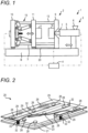
- an injection molding machine 1 is a horizontal injection molding machine 1.
- the injection molding machine 1 includes a mold clamping device 2 to be described below, an injection device 3, and a controller 4 configured to control the mold clamping device 2 and the injection device 3.
- the injection device 3 is shown in a simplified form in FIG. 1 .
- the injection device 3 includes a heating cylinder 5 and a screw (not shown) provided in the heating cylinder 5.
- the heating cylinder 5 has a hopper 6 for supplying an injection material and an injection nozzle 7.
- the mold clamping device 2 includes a fixed platen 9 fixed on a bed B, a mold clamping housing 10 that slides on the bed B, and a movable platen 11 that also slides on the bed B.
- the fixed platen 9 and the mold clamping housing 10 are coupled by a plurality of, for example, four tie bars 13, 13, ...
- the movable platen 11 penetrates the tie bars 13, 13, ... and is slidable toward the fixed platen 9.
- a mold clamping mechanism 15 is provided between the mold clamping housing 10 and the movable platen 11.
- the fixed platen 9 and the movable platen 11 are respectively provided with molds 16 and 17. Accordingly, when the mold clamping mechanism 15 is driven, the molds 16 and 17 are opened and closed.
- the mold clamping mechanism 15 may be a hydraulically driven mold clamping cylinder, and the type is not limited. In the present embodiment, a toggle mechanism is adopted.
- the mold clamping device may include a mold clamping housing provided slidably on the bed, a plurality of tie bars coupling the fixed platen and the mold clamping housing, and the toggle mechanism provided between the mold clamping housing and the movable platen.
- the mold clamping device 2 has a safety mat 20 according to the present embodiment which will be described in detail below. More specifically, the safety mat 20 is laid on the bed B and is provided between the fixed platen 9 and the movable platen 11. The safety mat 20 is connected to the controller 4. Although not shown in FIG. 1 , the mold clamping device 2 is closed by a safety door, and safety is ensured by preventing workers from entering inside while the injection molding machine 1 is in operation. A worker may open the safety door and intrude into the mold clamping device 2 at the time of maintenance. When a worker intrudes, the safety mat 20 detects the intrusion and notifies the controller 4. The controller 4 is configured to prohibit driving of the mold clamping device 2 and the injection device 3.
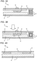
- FIG. 2 shows the safety mat 20 according to the present embodiment.
- the safety mat 20 includes a bottom board 21, a pressure-sensitive switch mat 23 provided on the bottom board 21, and a step board 25 disposed on the pressure-sensitive switch mat 23.
- the bottom board 21 may be made of any material, and in the present embodiment is made of a metal plate.
- the bottom board 21 is a member in contact with the bed B (see FIG. 1 ).
- the pressure-sensitive switch mat 23 may be of various types available on the market.
- the pressure-sensitive switch mat 23 is of a type that includes a pressure-sensitive conductive sheet.
- the pressure-sensitive switch mat 23 includes a bottom sheet, a pressure-sensitive conductive sheet provided on the bottom sheet, and a flexible surface sheet provided on the pressure-sensitive conductive sheet.
- the pressure-sensitive conductive sheet is formed of a rubber material which is an insulator. A large number of conductive particles are mixed in the rubber material. When the pressure-sensitive conductive sheet is compressed, the conductive particles therein come into contact with each other at a compressed portion, thereby establishing electrical conductivity.
- the surface sheet and the bottom sheet are each provided with an electrode film, and they are in contact with the pressure-sensitive conductive sheet. Accordingly, when a load acts on the surface sheet, a portion to which the load is applied is deformed, the pressure-sensitive conductive sheet is compressed, and electrical conductivity is established.
- the surface sheet is made of a flexible material such as rubber.
- the step board 25 is provided so as not to prevent high temperature substances from adhering to the surface sheet of the pressure-sensitive switch mat 23 and causing damage.
- the material of the step board 25 is not critical, but it is preferable to use a metal plate such as an aluminum plate, that is, an aluminum alloy plate, a stainless steel plate, or a steel plate. This is because the metal plate has high heat resistance and does not deteriorate even if a high temperature substance falls thereon.
- a surface of the step board 25 is subjected to an uneven processing 26 for sliding.
- the step board is preferably made of an aluminum plate or a stainless steel plate or a steel plate.
- a plurality of load transferring members 28, 28, ... are provided on a back surface of the step board 25.
- the load transferring members 28, 28, ... may be made of any material.
- the members are formed in a plate shape from a rubber material, that is, an elastomer.
- the plurality of load transferring members 28, 28, ... are arranged at intervals and are attached to the back surface of the step board 25.
- the load acting on the step board 25 acts on the pressure-sensitive switch mat 23 via the small load transferring members 28, 28, ..., so that the load can be accurately detected.
- reinforcing ribs 29, 29, ... are attached to the back surface of the step board 25, and the load transferring members 28, 28, ... are fixed to the reinforcing ribs 29, 29, ...
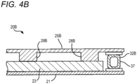
- FIG. 3A shows a cross section of the safety mat 20, in which the load transferring member 28 is fixed to a lower surface of the reinforcing rib 29 by a screw 30.
- the step board is provided with a plurality of reinforcing ribs, and the plurality of load transferring members are fixed to the reinforcing ribs.
- the bottom board 21 and the step board 25 have a larger area than the pressure-sensitive switch mat 23. Accordingly, peripheral edges of the bottom board 21 and the step board 25 protrude outward beyond the pressure-sensitive switch mat 23.
- the bottom board 21 and the step board 25 are connected to each other by a plurality of elastic support members 32, 32, ... at the portions protruding outward.
- the elastic support member 32, 32, ... may be made of any material as long as it is capable of elastically supporting the step board 25. In the present embodiment, the member is made of a spring 33.
- the safety mat includes: a bottom board having an area larger than that of the pressure-sensitive switch mat and disposed below the pressure-sensitive switch mat; and a plurality of elastic support members,
- the elastic support member is preferably made of a spring.
- the safety mat 20 according to the present embodiment is as shown in FIG. 3A when no load is applied to the step board 25. That is, the step board 25 is supported by the elastic support members 32, and the load transferring members 28 are separated from the pressure-sensitive switch mat 23. Accordingly, the pressure-sensitive switch mat 23 is not deformed, and no load is detected.
- the elastic support member 32 is compressed by the load.
- the load transferring member 28 comes into contact with the pressure-sensitive switch mat 23, and pushes the pressure-sensitive switch mat 23 downward.
- the pressure-sensitive switch mat 23 is deformed and the load is detected.
- the controller 4 (see FIG. 1 ) is notified. The controller 4 determines that a worker has intruded the mold clamping device 2.
- the step board 25 is on a top surface. Accordingly, the pressure-sensitive switch mat 23 is less likely to be damaged.
- the injection molding machine 1 see FIG. 1
- the high-temperature molten resin may fall onto the safety mat 20. Even if the molten resin falls onto the safety mat 20, the pressure-sensitive switch mat 23 is not damaged by being protected by the step board 25.
- FIG. 4A shows a safety mat 20A according to a modified second embodiment.
- a reinforcing rib is not provided on the back surface of the step board 25.
- the plurality of load transferring members 28, 28, ... are directly fixed to the step board 25.
- the load transferring members 28, 28, ... are fixed to the step board 25 by an adhesive rather than by screws.
- the elastic support member is not provided.
- the step board 25 is supported on the pressure-sensitive switch mat 23 by the plurality of load transferring members 28, 28, ...
- the step board 25 is formed to be relatively light, the deformation of the pressure-sensitive switch mat 23 is small. Therefore, no load is detected in this state.
- a deformation amount of the pressure-sensitive switch mat 23 increases, and the load is detected.
- FIG. 4B shows a safety mat 20B according to a third embodiment.
- load transferring members 28B and 28B are integrally formed with a step board 25B. That is, the load transferring members 28, 28, ... are formed from the same material as the step board 25B.
- an elastic support member 32B is formed of a rubber tube 37.
- a part of the weight of the step board 25B acts on the pressure-sensitive switch mat 23 via the load transferring members 28B, 28B, ...
- most of the weight of the step board 25B is supported by the rubber tube 37, so that the load is not detected.
- the rubber tube 37 is compressed, the pressure-sensitive switch mat 23 is deformed due to the load transferring members 28B, 28B, ..., and the load is detected.
- the step board 25 have been described as preferably being made of metal.
- the step board may be made of a polyimide resin, a ceramic composite material, or a fiberglass composite material. These are materials used as heat insulating boards. Accordingly, even if a high temperature substance adheres to the step board 25, heat conduction to the surface sheet of the pressure-sensitive switch mat 23 can be prevented, and the surface sheet can be protected.
- the load transferring member 28 may be made of any material. Similar to the step board 25, the load transferring member 28 may be made of a polyimide resin, a ceramic composite material, or a fiberglass composite material. Alternatively, the load transferring member 28 may be made of metal. That is, the load transferring member may be made of rubber or metal.
Landscapes
- Engineering & Computer Science (AREA)
- Mechanical Engineering (AREA)
- Manufacturing & Machinery (AREA)
- Chemical & Material Sciences (AREA)
- Physics & Mathematics (AREA)
- General Engineering & Computer Science (AREA)
- General Physics & Mathematics (AREA)
- Materials Engineering (AREA)
- Composite Materials (AREA)
- Analytical Chemistry (AREA)
- Dispersion Chemistry (AREA)
- Injection Moulding Of Plastics Or The Like (AREA)
- Moulds For Moulding Plastics Or The Like (AREA)
Abstract
Description
- The present invention relates to a safety mat configured to detect intrusion of a worker by the presence or absence of a load, a mold clamping device including the safety mat, and an injection molding machine including the safety mat.
- A pressure-sensitive switch mat that detects the presence or absence of a load, that is, a safety mat, is installed in a building where security is required to detect intrusion of a suspicious person, or is installed in an industrial machine to detect a worker entering the machine.
- There are various types of pressure-sensitive switch mats, some of which are configured as follows. That is, the pressure-sensitive switch mat includes a bottom sheet provided on a bottom surface, a surface sheet made of a flexible elastic insulating material such as a rubber sheet, and a pressure-sensitive conductive sheet provided between the bottom sheet and the surface sheet. The pressure-sensitive conductive sheet is made of a rubber material that is an insulator, and conductive particles mixed into the rubber material. When the pressure-sensitive conductive sheet is compressed, the conductive particles therein come into contact with each other at a compressed portion, thereby establishing electrical conductivity. The surface sheet and the bottom sheet are each provided with an electrode film, and the electrode film is in contact with the pressure-sensitive conductive sheet. Accordingly, when a load acts on the surface sheet, a portion where the load is applied is deformed, the pressure-sensitive conductive sheet becomes conductive due to compression, and the electrode films on the surface sheet and bottom sheet become conductive. The presence or absence of a load can be detected by applying a voltage to the electrode films in advance.
-
Patent Literature 1 proposes a pressure-sensitive switch mat of a different type. The pressure-sensitive switch mat described inPatent Literature 1 includes a step board portion and a plurality of tubular portions formed on a back surface side of the step board portion, and is integrally formed from rubber. A fluid is sealed in the tubular portion, and the fluid is connected to a pressure sensor via a connecting pipe. When a load acts on a surface of the step board portion, a portion is elastically deformed and the tubular portion on the back surface side is compressed. This causes the pressure of the fluid to increase and the increase is detected by the pressure sensor. - Patent Literature 1:
JPH06-043043A - The pressure-sensitive switch mat is excellent in that it can reliably detect the presence or absence of a load no matter where the load acts. For example, if the pressure-sensitive switch mat is installed on a bed on which a fixed platen and a movable platen are provided in a mold clamping device, the intrusion of a worker can be detected reliably, so that safety can be ensured. However, there are also problems. When a load acts on a surface of the pressure-sensitive switch mat, the portion is deformed and the load is detected. In other words, at least the surface sheet is flexible and is made of rubber or the like. In this case, if a high temperature substance adheres to the surface sheet, a portion thereof will melt and be damaged. For example, in a case where the pressure-sensitive switch mat is provided on a bed of a mold clamping device, if molten resin falls and adheres to the mat, that portion will be damaged.
- In view of the above problems, an object of the present disclosure is to provide a safety mat that will not be damaged even if a high temperature substance adheres thereto, and a mold clamping device and an injection molding machine provided with such a safety mat.
- Other problems and novel features will become apparent from description of the present description and the accompanying drawings.
- The present inventors have found that the above problem can be solved by configuring a safety mat as follows. That is, the present disclosure relates to a safety mat including: a pressure-sensitive switch mat whose surface is made of a flexible sheet; a step board disposed on the pressure-sensitive switch mat; and a plurality of load transferring members arranged at intervals between the pressure-sensitive switch mat and the step board. A load acting on the step board is detected by the pressure-sensitive switch mat via the plurality of load transferring members.
- According to the present disclosure, it is possible to provide a safety mat in which the pressure-sensitive switch mat is protected by the step board so as to be prevented from being damaged even if a high temperature substance adheres thereto.
-
- [
FIG. 1] FIG. 1 is a front view showing an injection molding machine according to the present embodiment. - [
FIG. 2] FIG. 2 is a perspective view showing a safety mat according to the present embodiment. - [
FIG. 3A] FIG. 3A is a side sectional view showing a part of the safety mat according to the present embodiment. - [
FIG. 3B] FIG. 3B is a side sectional view showing a part of the safety mat according to the present embodiment. - [
FIG. 4A] FIG. 4A is a side sectional view showing a part of a safety mat according to a second embodiment. - [
FIG. 4B] FIG. 4B is a side sectional view showing a part of a safety mat according to a third embodiment. - Hereinafter, specific embodiments will be described in detail with reference to the drawings. The present disclosure is not limited to the following embodiments. In order to clarify the description, the following description and the drawings are simplified as appropriate. In the drawings, the same elements are denoted by the same reference numerals, and repeated description thereof is omitted as necessary. In addition, hatching may be omitted to avoid complicating the drawings.
- A safety mat according to the present embodiment includes: a pressure-sensitive switch mat having a surface formed of a flexible sheet and configured to detect presence or absence of a load; a step board disposed on the pressure-sensitive switch mat; and a plurality of load transferring members arranged at intervals between the pressure-sensitive switch mat and the step board,
in which a load acting on the step board is detected by the pressure-sensitive switch mat via the plurality of load transferring members. - Further, a mold clamping device according to the present embodiment includes: a fixed platen fixed to a bed; and a movable platen slidably provided on the bed and driven in a direction toward and away from the fixed platen,
in which the safety mat is provided on the bed. - Further, an injection molding machine according to the present embodiment includes: an injection device configured to inject a resin; and a mold clamping device configured to clamp a mold,
- in which the mold clamping device includes: a fixed platen fixed to a bed; and a movable platen slidably provided on the bed and driven in a direction toward and away from the fixed platen, and
- in which the safety mat is provided on the bed.
- The present embodiment will be described.
- As shown in
FIG. 1 , aninjection molding machine 1 according to the present embodiment is a horizontalinjection molding machine 1. Theinjection molding machine 1 includes amold clamping device 2 to be described below, aninjection device 3, and acontroller 4 configured to control themold clamping device 2 and theinjection device 3. Theinjection device 3 is shown in a simplified form inFIG. 1 . Theinjection device 3 includes aheating cylinder 5 and a screw (not shown) provided in theheating cylinder 5. Theheating cylinder 5 has ahopper 6 for supplying an injection material and aninjection nozzle 7. - The
mold clamping device 2 according to the present embodiment includes a fixedplaten 9 fixed on a bed B, amold clamping housing 10 that slides on the bed B, and amovable platen 11 that also slides on the bed B. The fixedplaten 9 and themold clamping housing 10 are coupled by a plurality of, for example, fourtie bars movable platen 11 penetrates the tie bars 13, 13, ... and is slidable toward the fixedplaten 9. Amold clamping mechanism 15 is provided between themold clamping housing 10 and themovable platen 11. The fixedplaten 9 and themovable platen 11 are respectively provided withmolds mold clamping mechanism 15 is driven, themolds mold clamping mechanism 15 may be a hydraulically driven mold clamping cylinder, and the type is not limited. In the present embodiment, a toggle mechanism is adopted. - That is, the mold clamping device may include a mold clamping housing provided slidably on the bed, a plurality of tie bars coupling the fixed platen and the mold clamping housing, and the toggle mechanism provided between the mold clamping housing and the movable platen.
- The
mold clamping device 2 according to the present embodiment has asafety mat 20 according to the present embodiment which will be described in detail below. More specifically, thesafety mat 20 is laid on the bed B and is provided between the fixedplaten 9 and themovable platen 11. Thesafety mat 20 is connected to thecontroller 4. Although not shown inFIG. 1 , themold clamping device 2 is closed by a safety door, and safety is ensured by preventing workers from entering inside while theinjection molding machine 1 is in operation. A worker may open the safety door and intrude into themold clamping device 2 at the time of maintenance. When a worker intrudes, thesafety mat 20 detects the intrusion and notifies thecontroller 4. Thecontroller 4 is configured to prohibit driving of themold clamping device 2 and theinjection device 3. -
FIG. 2 shows thesafety mat 20 according to the present embodiment. Thesafety mat 20 includes abottom board 21, a pressure-sensitive switch mat 23 provided on thebottom board 21, and astep board 25 disposed on the pressure-sensitive switch mat 23. Thebottom board 21 may be made of any material, and in the present embodiment is made of a metal plate. Thebottom board 21 is a member in contact with the bed B (seeFIG. 1 ). - The pressure-
sensitive switch mat 23 may be of various types available on the market. In the present embodiment, the pressure-sensitive switch mat 23 is of a type that includes a pressure-sensitive conductive sheet. Although not shown inFIG. 2 , the pressure-sensitive switch mat 23 includes a bottom sheet, a pressure-sensitive conductive sheet provided on the bottom sheet, and a flexible surface sheet provided on the pressure-sensitive conductive sheet. The pressure-sensitive conductive sheet is formed of a rubber material which is an insulator. A large number of conductive particles are mixed in the rubber material. When the pressure-sensitive conductive sheet is compressed, the conductive particles therein come into contact with each other at a compressed portion, thereby establishing electrical conductivity. The surface sheet and the bottom sheet are each provided with an electrode film, and they are in contact with the pressure-sensitive conductive sheet. Accordingly, when a load acts on the surface sheet, a portion to which the load is applied is deformed, the pressure-sensitive conductive sheet is compressed, and electrical conductivity is established. Whatever type of pressure-sensitive switch mat 23 is employed, at least the surface sheet is made of a flexible material such as rubber. - The
step board 25 is provided so as not to prevent high temperature substances from adhering to the surface sheet of the pressure-sensitive switch mat 23 and causing damage. The material of thestep board 25 is not critical, but it is preferable to use a metal plate such as an aluminum plate, that is, an aluminum alloy plate, a stainless steel plate, or a steel plate. This is because the metal plate has high heat resistance and does not deteriorate even if a high temperature substance falls thereon. A surface of thestep board 25 is subjected to anuneven processing 26 for sliding. - The step board is preferably made of an aluminum plate or a stainless steel plate or a steel plate.
- A plurality of
load transferring members step board 25. Theload transferring members load transferring members step board 25. The load acting on thestep board 25 acts on the pressure-sensitive switch mat 23 via the smallload transferring members ribs step board 25, and theload transferring members ribs FIG. 3A shows a cross section of thesafety mat 20, in which theload transferring member 28 is fixed to a lower surface of the reinforcingrib 29 by ascrew 30. - In this way, it is preferable that the step board is provided with a plurality of reinforcing ribs, and the plurality of load transferring members are fixed to the reinforcing ribs.
- In the
safety mat 20 according to the present embodiment, thebottom board 21 and thestep board 25 have a larger area than the pressure-sensitive switch mat 23. Accordingly, peripheral edges of thebottom board 21 and thestep board 25 protrude outward beyond the pressure-sensitive switch mat 23. Thebottom board 21 and thestep board 25 are connected to each other by a plurality ofelastic support members elastic support member step board 25. In the present embodiment, the member is made of aspring 33. - As described above, it is preferable that the safety mat includes: a bottom board having an area larger than that of the pressure-sensitive switch mat and disposed below the pressure-sensitive switch mat; and a plurality of elastic support members,
- in which the plurality of elastic support members are provided on the bottom board while avoiding the pressure-sensitive switch mat, and support the step board, and
- in which the elastic support members are configured to be compressed when a load is applied to the step board.
- The elastic support member is preferably made of a spring.
- Operation of the
safety mat 20 according to the present embodiment will be described. Thesafety mat 20 according to the present embodiment is as shown inFIG. 3A when no load is applied to thestep board 25. That is, thestep board 25 is supported by theelastic support members 32, and theload transferring members 28 are separated from the pressure-sensitive switch mat 23. Accordingly, the pressure-sensitive switch mat 23 is not deformed, and no load is detected. - A worker stands on the
safety mat 20. Then, as shown inFIG. 3B , a downward load acts on thestep board 25. Theelastic support member 32 is compressed by the load. When theelastic support member 32 is compressed, theload transferring member 28 comes into contact with the pressure-sensitive switch mat 23, and pushes the pressure-sensitive switch mat 23 downward. Then, as indicated byreference numeral 35, the pressure-sensitive switch mat 23 is deformed and the load is detected. When the pressure-sensitive switch mat 23 detects the load, the controller 4 (seeFIG. 1 ) is notified. Thecontroller 4 determines that a worker has intruded themold clamping device 2. - In the
safety mat 20 according to the present embodiment, thestep board 25 is on a top surface. Accordingly, the pressure-sensitive switch mat 23 is less likely to be damaged. In the injection molding machine 1 (seeFIG. 1 ) according to the present embodiment, if purging is performed with theinjection nozzle 7 in contact with themold 16, that is, if a so-called in-mold purging is performed, the high-temperature molten resin may fall onto thesafety mat 20. Even if the molten resin falls onto thesafety mat 20, the pressure-sensitive switch mat 23 is not damaged by being protected by thestep board 25. - The
safety mat 20 according to the present embodiment can be modified in various ways.FIG. 4A shows asafety mat 20A according to a modified second embodiment. In the second embodiment, a reinforcing rib is not provided on the back surface of thestep board 25. The plurality ofload transferring members step board 25. Theload transferring members step board 25 by an adhesive rather than by screws. Further, in the second embodiment, the elastic support member is not provided. Thestep board 25 is supported on the pressure-sensitive switch mat 23 by the plurality ofload transferring members step board 25 is formed to be relatively light, the deformation of the pressure-sensitive switch mat 23 is small. Therefore, no load is detected in this state. When a worker stands on thestep board 25, a deformation amount of the pressure-sensitive switch mat 23 increases, and the load is detected. -
FIG. 4B shows asafety mat 20B according to a third embodiment. In the third embodiment, load transferringmembers step board 25B. That is, theload transferring members step board 25B. In the third embodiment, anelastic support member 32B is formed of arubber tube 37. When no load is applied to thestep board 25B, most of the weight of thestep board 25B acts on therubber tube 37. A part of the weight of thestep board 25B acts on the pressure-sensitive switch mat 23 via theload transferring members step board 25B is supported by therubber tube 37, so that the load is not detected. When a worker stands on thestep board 25, therubber tube 37 is compressed, the pressure-sensitive switch mat 23 is deformed due to theload transferring members - The
step board 25 have been described as preferably being made of metal. Alternatively, the step board may be made of a polyimide resin, a ceramic composite material, or a fiberglass composite material. These are materials used as heat insulating boards. Accordingly, even if a high temperature substance adheres to thestep board 25, heat conduction to the surface sheet of the pressure-sensitive switch mat 23 can be prevented, and the surface sheet can be protected. It has been described above that theload transferring member 28 may be made of any material. Similar to thestep board 25, theload transferring member 28 may be made of a polyimide resin, a ceramic composite material, or a fiberglass composite material. Alternatively, theload transferring member 28 may be made of metal. That is, the load transferring member may be made of rubber or metal. - Although the invention made by the present inventor has been specifically described above based on the embodiments, it is needless to say that the present invention is not limited to the embodiments described above, and various modifications can be made without departing from the scope of the invention. The plurality of examples described above may be appropriately combined.
- According to the present disclosure, it is possible to provide a safety mat that will not be damaged even if a high temperature substance adheres thereto, and a mold clamping device and an injection molding machine provided with such a safety mat.
- Although the present invention has been described in detail with reference to specific embodiments, it will be apparent to those skilled in the art that various changes and modifications can be made without departing from the spirit and scope of the present invention.
- The present application is based on
Japanese Patent Application No. 2022-011326 filed on January 27, 2022 -
1 Injection molding machine 2 Mold clamping device 3 Injection device 4 Controller 5 Heating cylinder 6 Hopper 7 Injection nozzle 9 Fixed platen 10 Mold clamping housing 11 Movable platen 13 Tie bar 15 Mold clamping mechanism 16 Mold 17 Mold 20, 20A, 20B Safety mat 21 Bottom board 23 Pressure- sensitive switch mat 25, 25B Step board 26 Uneven processing 28, 28B Load transferring member 29 Reinforcing rib 30 Screw 32, 32B Elastic support member 33 Spring 35 Deformation 37 Rubber tube B Bed
Claims (9)
- A safety mat, comprising:a pressure-sensitive switch mat having a surface formed of a flexible sheet and configured to detect presence or absence of a load;a step board disposed on the pressure-sensitive switch mat; anda plurality of load transferring members arranged at intervals between the pressure-sensitive switch mat and the step board,wherein a load acting on the step board is detected by the pressure-sensitive switch mat via the plurality of load transferring members.
- The safety mat according to claim 1, wherein the load transferring member is made of rubber or metal.
- The safety mat according to claim 1 or 2, wherein the step board is made of an aluminum plate or a stainless steel plate or a steel plate.
- The safety mat according to any one of claims 1 to 3, wherein the step board is provided with a plurality of reinforcing ribs, and the plurality of load transferring members are fixed to the reinforcing ribs.
- The safety mat according to any one of claims 1 to 4, further comprising:a bottom board having an area larger than that of the pressure-sensitive switch mat and disposed below the pressure-sensitive switch mat; anda plurality of elastic support members,wherein the plurality of elastic support members are provided on the bottom board while avoiding the pressure-sensitive switch mat, and support the step board, andwherein the elastic support members are configured to be compressed when a load is applied to the step board.
- The safety mat according to claim 5, wherein the elastic support member is a spring.
- A mold clamping device comprising:a fixed platen fixed to a bed; anda movable platen slidably provided on the bed and driven in a direction toward and away from the fixed platen,wherein the safety mat according to any one of claims 1 to 6 is provided on the bed.
- The mold clamping device according to claim 7, further comprising:a mold clamping housing slidably provided on the bed;a plurality of tie bars coupling the fixed platen and the mold clamping housing; anda toggle mechanism provided between the mold clamping housing and the movable platen.
- An injection molding machine comprising:an injection device configured to inject a resin; anda mold clamping device configured to clamp a mold,wherein the mold clamping device includes:a fixed platen fixed to a bed; anda movable platen slidably provided on the bed and driven in a direction toward and away from the fixed platen, andwherein the safety mat according to any one of claims 1 to 6 is provided on the bed.
Applications Claiming Priority (2)
| Application Number | Priority Date | Filing Date | Title |
|---|---|---|---|
| JP2022011326A JP2023109650A (en) | 2022-01-27 | 2022-01-27 | Safety mat and mold clamping device and injection molding machine |
| PCT/JP2023/000338 WO2023145418A1 (en) | 2022-01-27 | 2023-01-10 | Safety mat, mold clamping device, and injection molding machine |
Publications (2)
| Publication Number | Publication Date |
|---|---|
| EP4471394A1 true EP4471394A1 (en) | 2024-12-04 |
| EP4471394A4 EP4471394A4 (en) | 2025-06-04 |
Family
ID=87471139
Family Applications (1)
| Application Number | Title | Priority Date | Filing Date |
|---|---|---|---|
| EP23746635.4A Pending EP4471394A4 (en) | 2022-01-27 | 2023-01-10 | Safety mat, mold clamping device, and injection molding machine |
Country Status (5)
| Country | Link |
|---|---|
| US (1) | US20250128461A1 (en) |
| EP (1) | EP4471394A4 (en) |
| JP (1) | JP2023109650A (en) |
| CN (1) | CN118613701A (en) |
| WO (1) | WO2023145418A1 (en) |
Family Cites Families (16)
| Publication number | Priority date | Publication date | Assignee | Title |
|---|---|---|---|---|
| JPH06104314B2 (en) * | 1986-06-30 | 1994-12-21 | 日立電線株式会社 | Robot security equipment |
| GB2248723A (en) * | 1990-09-08 | 1992-04-15 | Cyril John Peachey | Safety switch mat |
| JP2544114Y2 (en) * | 1991-07-26 | 1997-08-13 | 株式会社タニタ | Scale platform |
| JP2000131162A (en) * | 1998-10-28 | 2000-05-12 | Ks Techno Kk | Mat sensor |
| JP3787292B2 (en) * | 2001-09-27 | 2006-06-21 | 新キャタピラー三菱株式会社 | Anti-vibration floor mat |
| KR200363781Y1 (en) * | 2004-07-21 | 2004-10-11 | 주식회사 엘지화학 | Stiffness reinforced sandwich panel for house access floor system |
| JP2009136477A (en) * | 2007-12-06 | 2009-06-25 | Panasonic Corp | Biological signal detection device |
| DE102009014248B4 (en) * | 2009-03-20 | 2012-06-14 | Sumitomo (Shi) Demag Plastics Machinery Gmbh | Walk-in safety floor |
| JP5554270B2 (en) * | 2011-03-15 | 2014-07-23 | 住友建機株式会社 | Construction machine floor mats and construction machinery |
| AT512816B1 (en) * | 2012-04-23 | 2014-03-15 | Engel Austria Gmbh | Safety device for an injection molding machine |
| JP2014032028A (en) * | 2012-08-01 | 2014-02-20 | Koowa Corporation:Kk | Weight detecting device |
| DE102015120368B3 (en) * | 2015-11-25 | 2016-11-03 | Pilz Gmbh & Co. Kg | Pressure-sensitive protective device for monitoring a technical system |
| KR101864232B1 (en) * | 2016-07-18 | 2018-06-05 | 안협전자주식회사 | Safety mat including contactless type pressure sensor and system including the same |
| JP6739882B2 (en) * | 2018-07-11 | 2020-08-12 | 株式会社日本製鋼所 | Safety equipment for large injection molding machines |
| JP6873585B1 (en) * | 2020-03-23 | 2021-05-19 | 株式会社日本製鋼所 | Vertical injection molding machine with removable scaffolding |
| JP7368847B2 (en) | 2020-06-30 | 2023-10-25 | 株式会社海空牧場 | cicada trap |
-
2022
- 2022-01-27 JP JP2022011326A patent/JP2023109650A/en active Pending
-
2023
- 2023-01-10 US US18/730,407 patent/US20250128461A1/en active Pending
- 2023-01-10 WO PCT/JP2023/000338 patent/WO2023145418A1/en not_active Ceased
- 2023-01-10 CN CN202380018730.1A patent/CN118613701A/en active Pending
- 2023-01-10 EP EP23746635.4A patent/EP4471394A4/en active Pending
Also Published As
| Publication number | Publication date |
|---|---|
| CN118613701A (en) | 2024-09-06 |
| US20250128461A1 (en) | 2025-04-24 |
| EP4471394A4 (en) | 2025-06-04 |
| WO2023145418A1 (en) | 2023-08-03 |
| JP2023109650A (en) | 2023-08-08 |
Similar Documents
| Publication | Publication Date | Title |
|---|---|---|
| CA1045696A (en) | Pressure sensitive mat switch construction | |
| US20250128461A1 (en) | Safety mat, mold clamping device, and injection molding machine | |
| KR20200068582A (en) | Resin-molding device, and method for producing resin-molded product | |
| EP2139086B1 (en) | Flexible membrane gland plate | |
| KR930004049A (en) | Injection device of molding material and method | |
| JP2006297818A (en) | Resin sealed mold assembly | |
| KR101638747B1 (en) | Support bar and the process of manufacture for glass load cassette | |
| WO2017007065A1 (en) | Autoclave device capable of removing bubbles in multiple stages | |
| JP6713231B2 (en) | Vertical injection molding machine with expansion bed | |
| US20060255500A1 (en) | Molding systems and processes | |
| CN217466513U (en) | STP resin mechanical property testing device | |
| JP2577302B2 (en) | Vent type vertical injection equipment | |
| KR102494206B1 (en) | Resin molding apparatus and resin molded product manufacturing method | |
| CN214562752U (en) | Electric eye protection cover for injection molding machine blanking detection | |
| US12039515B2 (en) | Mobile POS terminal | |
| CN220331889U (en) | Screw rod clamp plate | |
| CZ5551U1 (en) | Compensator of spatial deflection of supporting plates of rubber injection press | |
| JPH0347719A (en) | In-mold coating method for plastic | |
| EP0419262B1 (en) | Tension band for a cathode ray tube | |
| WO2015163501A1 (en) | Autoclave device for defoamation and operating method therefor | |
| CN220625306U (en) | Detection tool for automobile part mold | |
| CN1982172A (en) | Foam box for transferring substrate | |
| CN114928937A (en) | Tear-resistant flexible circuit board | |
| TW202110605A (en) | Resin sealing-forming device and resin sealing-forming method to prevent the exposed member of the electronic component from cracking and resin leakage | |
| CN223225289U (en) | A battery plate anti-reverse discharge device |
Legal Events
| Date | Code | Title | Description |
|---|---|---|---|
| STAA | Information on the status of an ep patent application or granted ep patent |
Free format text: STATUS: THE INTERNATIONAL PUBLICATION HAS BEEN MADE |
|
| PUAI | Public reference made under article 153(3) epc to a published international application that has entered the european phase |
Free format text: ORIGINAL CODE: 0009012 |
|
| STAA | Information on the status of an ep patent application or granted ep patent |
Free format text: STATUS: REQUEST FOR EXAMINATION WAS MADE |
|
| 17P | Request for examination filed |
Effective date: 20240725 |
|
| AK | Designated contracting states |
Kind code of ref document: A1 Designated state(s): AL AT BE BG CH CY CZ DE DK EE ES FI FR GB GR HR HU IE IS IT LI LT LU LV MC ME MK MT NL NO PL PT RO RS SE SI SK SM TR |
|
| DAV | Request for validation of the european patent (deleted) | ||
| DAX | Request for extension of the european patent (deleted) | ||
| A4 | Supplementary search report drawn up and despatched |
Effective date: 20250506 |
|
| RIC1 | Information provided on ipc code assigned before grant |
Ipc: H01H 3/14 20060101ALI20250428BHEP Ipc: F16P 3/12 20060101ALI20250428BHEP Ipc: B29C 45/84 20060101ALI20250428BHEP Ipc: G01L 1/20 20060101AFI20250428BHEP |