EP4471385A1 - Functional method of linearizing the dependence of the force exerted on the reaction element of a flowmeter with the flow rate, and linear reaction flowmeter configured on the basis of that method - Google Patents
Functional method of linearizing the dependence of the force exerted on the reaction element of a flowmeter with the flow rate, and linear reaction flowmeter configured on the basis of that method Download PDFInfo
- Publication number
- EP4471385A1 EP4471385A1 EP23020258.2A EP23020258A EP4471385A1 EP 4471385 A1 EP4471385 A1 EP 4471385A1 EP 23020258 A EP23020258 A EP 23020258A EP 4471385 A1 EP4471385 A1 EP 4471385A1
- Authority
- EP
- European Patent Office
- Prior art keywords
- reaction
- moment
- flow rate
- balancing
- linearizer
- Prior art date
- Legal status (The legal status is an assumption and is not a legal conclusion. Google has not performed a legal analysis and makes no representation as to the accuracy of the status listed.)
- Granted
Links
Images



Classifications
-
- G—PHYSICS
- G01—MEASURING; TESTING
- G01F—MEASURING VOLUME, VOLUME FLOW, MASS FLOW OR LIQUID LEVEL; METERING BY VOLUME
- G01F1/00—Measuring the volume flow or mass flow of fluid or fluent solid material wherein the fluid passes through a meter in a continuous flow
- G01F1/76—Devices for measuring mass flow of a fluid or a fluent solid material
- G01F1/78—Direct mass flowmeters
- G01F1/80—Direct mass flowmeters operating by measuring pressure, force, momentum, or frequency of a fluid flow to which a rotational movement has been imparted
-
- G—PHYSICS
- G01—MEASURING; TESTING
- G01F—MEASURING VOLUME, VOLUME FLOW, MASS FLOW OR LIQUID LEVEL; METERING BY VOLUME
- G01F25/00—Testing or calibration of apparatus for measuring volume, volume flow or liquid level or for metering by volume
- G01F25/10—Testing or calibration of apparatus for measuring volume, volume flow or liquid level or for metering by volume of flowmeters
Definitions
- the functional method of linearization is based on the appropriate insertion in the structure of a reaction flowmeter, of a specific functional element called “linearizer”, which allows establishing an expression, inherently and directly linear, between the force exerted on the reaction element and the measured flow rate.
- the reaction flowmeter configured based on the proposed linearization method, presents in its structure, in addition to some blocks and functional elements specific to a reaction flowmeter, known in itself, a totally innovative solution of the outlet nozzle with variable area from the reaction element, containing a linearization element called "linearizer" which, in order to effectively achieve a linear dependence between reaction force and flow rate, imposed besides the definition of the geometric profile and its functional-constructive coupling in the structure of the flow meter, also the realization of the coupling of the reaction tube with a moment transducer that ensures, by balancing the reaction moment, both its measurement and the angular positioning of the reaction element, implicitly of the variable area of the nozzle exit of the reaction element.
- linearizer a linearization element
- the method ensures, in an intrinsically functional way, the linear dependence, with the mass flow rate of the fluid to be measured Q m , of the reaction force F R , generated when it passes through the reaction element of the flowmeter and applied to it, dependence that also establishes and the manner of measuring the force F R , in order to determine the flow rate Q m .
- the method involves the successive completion of two stages.
- the first stage establishes the analytical bases of the method, presented through its application algorithm.
- the second stage establishes the basic structural scheme and the basic configurations of flowmeters with linear reaction, determined based on the considerations presented in the first stage of the method.
- Step 1 of the method has as its starting point the definition of the currently known reference equations, related to flowmeters with non-linear reaction, from which it started for the development of the present method of linearization of the dependence between the mass flow rate and the reaction force generated by it, when passing the fluid through the reaction element of the flowmeter, respectively:
- the solution requires avoiding the extraction of the radical from a negative value (respectively an irrational number), by imposing the condition: k 1 P % Q m ⁇ A 1 ⁇ 1
- step 4 of the method the basic structural solution of the nozzle with variable area A 2 (Q m ), for the outlet of the reaction element, is configured.
- the nozzle is configured by the fluidic coupling of two concentric parts, a mobile one together with the reaction tube to which it belongs, and the other being immobile fixed to the output connection of the flowmeter.
- the area A 2 A 2 (Q m ) becomes the area of a circular crown with variable area, delimited on the outside by the inner wall (with diameter D e ) of the outlet of the reaction element, being part of it, and implicitly mobile together with it, rotating with the angle ⁇ E P% (Q m P% ) related to the symmetry axis of the rotation shaft (3) of the reaction tube (2).
- the area A 2 (Q m ) is delimited by the contour of a piece placed centrally, having the diameter D i .
- the method provides two versions of the variation of the area A 2 ( ⁇ E ) of the circular crown of the outlet nozzle of the reaction element, compared to the mass flow rate Q m .
- the outer diameter D e of the circular crown is kept constant, and the inner diameter D i varies with it.
- the inner diameter D i of the circular crown is kept constant, and the outer diameter D e varies with it.
- the symmetry axis of the "inner linearizer” is the same as the axis on which the center of the exit section of the reaction tube is positioned, in its angular displacement, together with it, being slightly curved with the radius Rc, the radius whose center is in the symmetry axis of the rotation shaft of the reaction tube.
- This part is immobile,being placed in the center of the inlet nozzle of the outlet connection of the flow meter.
- the axis of symmetry of the "outer linearizer” is the same as the axis on which the center of the exit section of the reaction tube is positioned, in its angular displacement together with it, being identical to the axis of symmetry of the immovable inner part, positioned centrally.
- the fluid coming out of the nozzle of the reaction element is taken over by the inlet nozzle of the outlet connection of the flow meter.
- Step 5 of the method considers the establishment of the profile of the linearizer.
- the profile of the linearizer is characterized by the coordinates ⁇ E P% , D L P% .
- the diameter of the "linearizer” has the following expressions:
- both the basic structural diagram of the flowmeters with linear reaction (with reference to Fig. 1 ) is defined, as well as, correlated with it, their reference configurations (with reference to Fig.2 and Fig.3 ),of implementation the provisions stipulated in the first stage of the method.
- the fluid with the flow rate to be measured Q m enters the flowmeter through the input connection (immobile)1, which represents, from a structural point of view, the Reference Block (BR). It ensures, constructively and functionally, the constant value of the reference parameter X R of the flowmeter, compared to the flow rate variation.
- immobile represents, from a structural point of view, the Reference Block (BR).
- the fluid coming out of the inlet connection 1 passes through the reaction tube 2, which changes its flow direction to 90°, causing the reaction force F R of the fluid to appear, which acts on the reaction tube 2, causing a potential rotation with respect to its rotation shaft 3, the fluid continuing its flow, through the output nozzle 4, together with which it forms the Reaction Element (ER), and then through the output connection 6 of the flowmeter.
- the basic structural diagram of these flowmeters in Fig.1 correlated with the graphic presentation in Fig.2 and Fig.3 , indicates the configuration mode of the outlet nozzle 4 of the reaction element, achieved by the interstice (circular flow crown) of the fluid flowing between the outlet wall of the reaction tube 2 (on the outside), which is mobile, and a centrally positioned piece (on the inside), which is immobile and concentric with it.
- Area A 2 of the outlet nozzle has the angular position ⁇ P% , related to the plane in which it is located, and has the shape of a circular crown.
- the symmetry axis of the "inner linearizer” is slightly curved, with the radius of curvature having the origin in the symmetry axis of the rotation shaft 3 of the reaction tube 2.
- reaction tube and implicitly the plane of the outlet nozzle section, are mobile and characterized by the same angular positioning ⁇ E (Q m P% ) .
- the Angular Positioning Block of the outlet nozzle (BPU) is composed of the flexible tape 23, fixed at one end by the screw 22, to the boss 21 of the reaction tube 2, it is rolled around the semicircumference of the disk 24, being fixed at the other end on the circumference of the disk 24, on the same rotation shaft and rigidly with it being also the hub 25, their assembly being able to rotate freely in the two bearings 26 (positioned left, right), placed on the two supports 27 (positioned left, right).
- the hub 25 is provided, perpendicular to its axis of symmetry, with a passage hole, also acting as a sliding bearing, for a rod 28, profiled at its lower end so that, on a shaft 29, fixed perpendicular to it, a mini-bearing 30, from stainless steel, is mounted .
- a mini-bearing 30 from stainless steel.
- two weights 31 and 32 equal to each other, are placed, with the surfaces protected against the physical-chemical action of the measured fluid.
- the rod 28 rests, by the mini-bearing 30, on the cam 33, specially profiled, corresponding to its polar coordinates ⁇ E , R c , correlated according to relation (14).
- the first output parameter namely the angle of rotation ⁇ E (Q m ) is applied, according to what was previously specified, to the "Angular Positioning Block of the outlet nozzle" (BPU), which determines at its output the angular positioning ⁇ E of its section, with area A 2 .
- BPU Angular Positioning Block of the outlet nozzle
- BEMR Balancing Block of the Reaction Moment
- the other output parameter of the Balancing Block of the Reaction Moment (BEMR), namely the balancing moment M E is applied to the Computing Block of the Rendering Parameter Q R of the measured flow rate Q m .
- the output signals of the pressure and temperature sensors are applied to the Computing Block of the Rendering Parameter the value Q R of the measured flow Q m .
- the radius of curvature of the axis of symmetry has its origin in the symmetry axis of the rotation shaft 3 of the reaction tube 2.
- FIG.4 A first structural example of making a flowmeter with linear reaction, according to this method, is presented in Fig.4 .
- the fluid to be measured enters the flowmeter through the inlet connection 1, continuing its flow through the reaction tube 2 (bent at 90° at its other end), with which it is freely coupled through the shaft 3, which allows the rotation of the reaction tube 2 from inlet connection 1.
- the essential modification compared to the flowmeter with non-linear reaction, consists in replacing in the configuration of the reaction element, only of the reaction tube 2 (having the outlet nozzle with constant area A 2 ), with a new configuration of the reaction element.
- This new configuration is made up of the reaction tube 2 and the outlet nozzle 4 of the reaction element, nozzle that ensures the discharge of the fluid through the circular crown delimited, in the plane of the outlet section of the reaction tube, on the outside, by the inner circular dewall 12 of the end of the reaction tube, and on the inside, of part 5, specially profiled, called “inner linearizer", which is immobile, being fixed to the output connection 6, through the rod 13 and the support 14, and centrally positioned, concentric with the outer wall 12.
- the outer wall 12, being part of the reaction tube 2 is mobile, rotating together with it with the angle ⁇ E P% , which is the angular position of the plane of the outlet section of the nozzle, implicitly of its exit area,
- the reaction element of the linear reaction flowmeter is constituted, on the one hand, by the reaction tube 2 and the outlet nozzle 4, which has the section with variable area A2, placed in the plane of the outlet section of the tube 2.
- the outlet nozzle 4 of the reaction element is formed by the fluidic coupling of the two parts 12 and 5, concentric and having the same axis of symmetry.
- the nozzle 15 which is immobile, and concentric with the nozzle 12, being fixed rigidly on the outlet connection 6 of the flow meter.
- the linearizer 5 which has a major contribution to achieving the linear dependence between the reaction force F R and the mass flow rate Q m .
- the three parts, the outer wall 12, the inner linearizer 5 and the nozzle 15 are positioned concentrically and symmetrically with respect to their common axis of symmetry, the axis which is slightly curvilinear with the radius of curvature Rc, which has its origin in the axis of symmetry of the shaft 3 and the end at the base of the inner linearizer 5, on its axis of symmetry.
- the reaction tube 2 is coupled with the moment transducer 10 (with elastic balancing), through the rigid and coaxial fixation of the shaft 3 of the reaction tube, with the torsion bar of the transducer 10.
- the mass flow rate Q m P% determines the generation of a proportional reaction force F R P% , which rotates the reaction tube 2 and implicitly the outer wall 12 of the nozzle of the reaction element, with the angle ⁇ P% , corresponding to balancing the moment of the reaction force, by that developed by the moment transducer.
- FIG. 5 A second structural example of the flowmeter with linear reaction is shown in Fig. 5 and 6 .
- the configuration of the flowmeter solution with linear reaction shown in Fig.5 is practically identical, from a fluidic point of view, to the one shown in Fig.4 .
- the solution in Fig. 4 uses a moment transducer with elastic balancing of M R
- the solution from Fig.5 and Fig. 6 uses a moment transducer with gravimetric balancing of M R .
- the presentation of the solution in Fig.5 and 6 refers in particular to this structural specificity of the flowmeter with linear reaction, regarding the method of taking and measuring, by balancing of, the reaction moment M R and implicitly of the mass flow rate Q m .
- the reaction tube 2 is provided, at its upper part, with a boss 21, with the median axis placed at a distance L 0 from the axis of symmetry of the shaft 3, boss in which is fixed by screw 22, flexible stainless tape 23.
- the flexible tape 23 is rolled on the disk 24, on half of its circumference, being fixed at its other end to this disk, in the middle zone of its circumference.
- the diameter D of the disk 24 is set in such a way that the disk rotates by 90° when the tape 23 is unwound with the length ⁇ L.
- the hub 25 is provided, perpendicular to its axis of symmetry, with a passage hole, which also acts as a sliding bearing, for a rod 28.
- the rod 28 is profiled at its lower end, so that a stainless steel mini-bearing 30 is mounted on a shaft 29, fixed perpendicular to it.
- the rod 28 is supported by the mini-bearing 30 on the cam 33.
- the gravimetric moment transducer ensures, functionally, the linear dependence of the angular displacement ⁇ E of the weight-bearing rod (displacement related to the balancing of the reaction moment M R ), both with the moment M R and with the corresponding angular displacement ⁇ E , of the reaction tube.
- the angular displacement ⁇ E of the hub 25 is measured, through contactless coupling, by the sensor 34, placed outside the measured fluid.
- the electrical output signal from the transducer 9, corresponding to the value of the measured moment M R (by default the value of the reaction force F R ), is applied to the block 16, for calculating the value of the measured flow rate Q m .
- the Q R signal is obtained to render the value of the measured flow rate Q m .
- the output signals of the pressure sensor 19 and the temperature sensor 20 are applied to the computing block 16 thus ensuring the correction, with the pressure and temperature, of the parameter Q R for rendering the value of calculation the measured flow rate Q m .
Landscapes
- Physics & Mathematics (AREA)
- Fluid Mechanics (AREA)
- General Physics & Mathematics (AREA)
- Measuring Volume Flow (AREA)
Abstract
Description
- Present invention refers to the technical solution for defining a method of directly functional linearization of the dependence of the force exerted on a reaction element in the structure of a flowmeter on the flow rate, and its implementation by a block having a specific role called "linearizer", in the configuration of the structure of a reaction flowmeter, which, based on the new functional working principle, allows a precise measurement of the flow rate over extended ranges, practically for any working fluid in the industrial environment.
- In the state of the art, there are known methods of linearizing the dependence, of a quadratic nature, between the flow rate measured by a flowmeter, and respectively the force developed on a reaction element in the structure of the flowmeter, thus called "reaction flowmeter"
- Thus, in the patent document
EP 4001856 "Reaction flowmeter without moving parts in individual, bypass and respectively extended configuration, and a method of flow measurement based on it", it is described a technical solution of a reaction flowmeter, in which a linear or quasi-linear dependence is realized between the output parameter of the flowmeter and the measured flow. Thus, a linearization solution is presented by means of a non-linear transformation cam of the reaction force (achieved in the opposite direction with the quadratic dependence of the reaction force on the flow rate) in the output parameter of the flowmeter so that the dependence between the output parameter and the measured flow rate Qm is thus linearized. - In its turn, the patent document
WO 9702470 (A1 - All these solutions have the disadvantage that they start from the use of reaction elements whose geometric configuration maintains, constant with respect to the flow rate, both the area of the inlet nozzle and that of the outlet nozzle, the functional equation being of quadratic dependence of the reaction force against of the measured flow rate, which causes a reduced value of the extension of the flow rate measurement range to be obtained.
- Bescause of this, trying to reduce this functional structural handicap, the technical solutions known up to now involve complicated technical solutions, with limited uses, and cumbersome and expensive constructive configurations and achievements, or simpler configurations but exposed to the diminishing of the measurement interval and/or the measurement precision, due to the potential deviation from linearization through execution and/or wear of their components.
- Technical problem solved by the present invention consists in a significant extension of the range (respectively of the turndown) of accurate flow measurement by a flow meter, for a very wide range of fluids, by directly transforming the mode of operation of the reaction element of the flow meter, defined by the functional equation of the quadratic dependence between the reaction force and the measured mass flow rate, and linearizing it by implementing in its structure of a block with a specific role, called " linearizer", which ensures the modification of the role of a component parameter of it, from a constant parameter to a variable parameter, proportional to the inverse of the measured flow rate, and changing accordingly, in a correlated way, the role and configuration of the outlet nozzle of the reaction element, from a nozzle with a constant area to a nozzle with a variable area depending on the flow rate.
- The functional method of linearization, according to the invention, is based on the appropriate insertion in the structure of a reaction flowmeter, of a specific functional element called "linearizer", which allows establishing an expression, inherently and directly linear, between the force exerted on the reaction element and the measured flow rate.
- The prerequisite of the proposed linearization consists in defining, on the one hand, that profile of the "linearizer" that allows the transformation of some parameters defining the functional equation of the reaction flowmeter, from basically constant parameters to variable parameters dependent on the measured flow rate, which allow the "intrinsic" linearization of the dependence relationship between the force exerted on the reaction element in the flowmeter structure and the measured flow rate, and on the other hand, the definition of the interrelationship and connection parameters with the other blocks in the flowmeter structure, which allow the linearizer to be inserted into an optimized configuration of the reaction flowmeter.
- The functional method of linearizing the dependence of the reaction force on the flow rate and the reaction flowmeter configured based on the method, according to the invention, present the following advantages.
- It ensures a significant increase, to a value equal to the square of the value of the turndown (the extension of the flow rate measurement range), related to the reaction flowmeters, known up to now having the non-linear dependence of the reaction force on the measured flow rate, changing the configuration of the reaction element of the reaction flowmeter, by transforming the role and configuration of its outlet nozzle, from a constant area nozzle, to a variable area nozzle, with the flow rate, thus ensuring the directly functional linearization, of the dependence of the reaction force, compared to the flow rate of the fluid that generates it, upon its passage through the reaction element.
- In this way, are eliminated multiple disadvantages related to linearization solutions, known up to now, which arise from the use of one or a combination of reaction elements with a non-linear dependence between the reaction force and the flow rate that produces it, when crossing it/them, to which an additional functional diagram is attached, that ensures by various processing options the linearization of the dependence of the output parameter of the flowmeter (and not of the reaction force), compared to the measured flow rate.
- The reaction flowmeter configured based on the proposed linearization method, presents in its structure, in addition to some blocks and functional elements specific to a reaction flowmeter, known in itself, a totally innovative solution of the outlet nozzle with variable area from the reaction element, containing a linearization element called "linearizer" which, in order to effectively achieve a linear dependence between reaction force and flow rate, imposed besides the definition of the geometric profile and its functional-constructive coupling in the structure of the flow meter, also the realization of the coupling of the reaction tube with a moment transducer that ensures, by balancing the reaction moment, both its measurement and the angular positioning of the reaction element, implicitly of the variable area of the nozzle exit of the reaction element.
- The use in the structure of the flowmeter made based on said method, as a transducer of the reaction moment, of a moment transducer with gravimetric balancing, provided with the correction with the temperature and pressure of the fluid, of the volume of the ballast pieces, and corresponding to their weight, with the Archimedean force of fluid, has the advantage of being used for a very wide range of liquids, including aggressive physico-chemical ones, used at pressures and temperatures in a wide range of values, unlike the some currently known flowmeters that use a moment transducer with elastic balancing, usable only for water and non-aggressive gases at very low pressures.
- An embodiment the method of functional linearization of the force dependence applied on the reaction element of a flowmeter on the measured flow rate, is given below, and of the flowmeter structure configured based on the method, in connection with
figures 1 ...6 , which represent: -
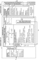
Fig. 1 Basic structural diagram of reaction flowmeters, with the linearization of the dependence of the reaction force exerted on the reaction element against the flow rate -
Fig.2 Reference structural diagram of the flowmeter with linear reaction, using a moment transducer with balancing by elastic torsion -
Fig.3 Reference structural diagram of the flowmeter with linear reaction, using a moment transducer with gravimetric balancing -
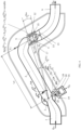
Fig.4 Longitudinal section through the flowmeter with linear reaction, using a moment transducer with balancing by elastic torsion -
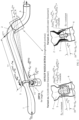
Fig.5 Longitudinal section through the linear reaction flowmeter, using a moment transducer with gravimetric balancing -
Fig.6 Section with an A-A plane of the flowmeter fromFig.5 . - The method ensures, in an intrinsically functional way, the linear dependence, with the mass flow rate of the fluid to be measured Qm, of the reaction force FR, generated when it passes through the reaction element of the flowmeter and applied to it, dependence that also establishes and the manner of measuring the force FR, in order to determine the flow rate Qm.
- The method involves the successive completion of two stages.
- The first stage establishes the analytical bases of the method, presented through its application algorithm.
- The second stage establishes the basic structural scheme and the basic configurations of flowmeters with linear reaction, determined based on the considerations presented in the first stage of the method.
- The first stage consists in going through, in their logical sequence, the following procedural steps, also explained through their analytical foundation.
Step 1 of the method has as its starting point the definition of the currently known reference equations, related to flowmeters with non-linear reaction, from which it started for the development of the present method of linearization of the dependence between the mass flow rate and the reaction force generated by it, when passing the fluid through the reaction element of the flowmeter, respectively: - The functional equation of the flowmeter with non-linear reaction:

where:- FR - reaction force;
- ρ - density of the measured fluid;
- Qm - measured mass flow rate;
- k1 - constructive parameter = constant, which has the expression:

where:- A1 - the area of the outlet from the inlet connection of the flowmeter, respectively of the inlet to the reaction tube;
- A2 -outlet area from the reaction tube;
- Additionally, the parameters that will be used in the following considerations are now presented, respectively:
- Qm P(%) - the value of the current mass flow measured, expressed, with reference to its percentage value P(%) compared to the value of the maximum flow Qm 100%, which has the expression:

- αE (P%) = α E (Qm P%)- the angle of rotation of the reaction tube, corresponding to the balancing, by the moment transducer, of the reaction moment MR P% = F R P% × LR, of the reaction force FR P% ( having the arm LR ), generated by the mass flow rate Qm P(%);
- βE P(%) = βE (Qm P%) - the rotation angle of the sensitive element of the moment transducer, corresponding to which it, developing the balancing moment ME P% = c × βE P(%) (where c - constructive constant), ensures the measuring of the reaction moment MR P% by balancing it, respectively ME P% =MR P%.
- At
step 2, starting from the previous determination (Bibliographic Reference 1) of the analytical expression (2) of the parameter k1, the present method ensures the change of its role, from the constant parameter k1 = ct, to the parameter k1 P%, variable depending on the flow rate value, according to the relationship:
- Qm 100% -maximum flow rate;
- k1 100% - the value of the parameter k1 corresponding to the maximum flow rate.
- Ensuring, functionally - constructively, the value of k1 P(%) according to expression (4), determines the achievement of the linear dependence between FR and Qm, this being demonstrated by replacing the parameter k1 with k1 P(%) in relation (1).
- This results in the expression:

- By processing, it is obtained:

- The relationship (6) demonstrates the assurance of the linear dependence between the force FR P% and the flow rate Qm P%.
- Next,
step 3 considers the modification, as a consequence, of the role of the outlet nozzle of the reaction element, from a nozzle with a constant area (A2 = constant), to a nozzle with a variable area with the flow rate Qm, respectively A2 = A2 (Qm). - In this sense, in order to determine the expression of the variable parameter A2, the equation (2) is processed, with reference to A2, by replacing k1 with k1 P(%), obtaining the equation:

- The solution of this equation, for values of A2 in accordance with those of A1, is the following:

- The solution requires avoiding the extraction of the radical from a negative value (respectively an irrational number), by imposing the condition:

- In
step 4 of the method, the basic structural solution of the nozzle with variable area A2 (Qm), for the outlet of the reaction element, is configured. - The nozzle, according to the method, is configured by the fluidic coupling of two concentric parts, a mobile one together with the reaction tube to which it belongs, and the other being immobile fixed to the output connection of the flowmeter.
- Thus now, the area A2 = A2 (Qm) becomes the area of a circular crown with variable area, delimited on the outside by the inner wall (with diameter De) of the outlet of the reaction element, being part of it, and implicitly mobile together with it, rotating with the angle α E P% (Qm P%) related to the symmetry axis of the rotation shaft (3) of the reaction tube (2).
- This angular displacement of the reaction tube is determined by the rotation angle βE P% (of torsion or gravitational displacement) of the sensitive element of the moment transducer, angle for which the moment transducer develops the moment ME to balance the reaction moment MR, by ensuring thus ME P% =MR P% = FR P%× LR, (where LR is the arm of the force FR ) and implicitly its measurement.
- On the inside, specific to the concept of the method, the area A2 (Qm) is delimited by the contour of a piece placed centrally, having the diameter Di.
- Consequently, the outlet nozzle of the reaction element has the general expression:

- The method provides two versions of the variation of the area A2 (α E) of the circular crown of the outlet nozzle of the reaction element, compared to the mass flow rate Qm.
- In the first version, compared to the variation of the flow rate Qm, the outer diameter De of the circular crown is kept constant, and the inner diameter Di varies with it.
- In the second version, compared to the variation of the flow rate Qm, the inner diameter Di of the circular crown is kept constant, and the outer diameter De varies with it.
- Thus, in the first variant, the circular crown with area A2 (α E)= A2 (Qm) is delimited on the outside by the inner wall (with diameter De = constant) of the outlet nozzle of the reaction element, being part of it, and mobile with it, rotating with the angle α E P% (Qm P%), corresponding to the angle βE P%, of rotating the sensitive element of the moment transducer, for which balancing ME P% =MR P% is ensured.
- On the inside, the circular crown with area A2 (Qm) is delimited by a centrally positioned part (named, due to its functional role, "inner linearizer"), having the contour profiled with the diameter Di P%, variable corresponding to the angular position α E P% (related to the flow rate Qm P%)) of the plan in which the area Qm P%) is located (and implicitly Di P%), resulting in Di P% = DLi(α P%) = DLi(Qm P%).
- The symmetry axis of the "inner linearizer" is the same as the axis on which the center of the exit section of the reaction tube is positioned, in its angular displacement, together with it, being slightly curved with the radius Rc, the radius whose center is in the symmetry axis of the rotation shaft of the reaction tube.
- The "inner linearizer" is immobile, being centrally placed rigidly against to the inlet nozzle, of the outlet connection of the flowmeter.
- Thus, the necessary value of the corresponding area A2 P% = A2 (α E P%), is obtained, according to relation (8), related to the angular position α E P% of the measuring section, (respectively of the reaction tube), which in turn determines, for the parameter k1, the value k1 P%, which ensures the linear dependence of the force FR on the flow rate Qm, according to relation (6).
- The fluid coming out of the nozzle of the reaction element is taken over by the inlet nozzle of the
outlet connection 6 of the flowmeter. - In the second variant, the area A2 (α E) = A2 (Qm) is delimited on the outside by the inner wall (with the diameter De = DLe P% = DLe P% (α E P%) of the exit of the reaction tube, being part of it, and movable with it, rotating with the angle α E P% (Qm P%),, angle corresponding to ensuring balancing ME P% =MR P%.
- Due to its functional role, this inner exit wall of the reaction tube is called "outer linearizer", its diameter DLe p%, being located in the plane of the area A2 P% = A2 (α E P%), plane related to the exit section of the tube of reaction, having the angular position α E (Qm P%).
- On the inside, the area A2 (Qm) is delimited by the outline of a piece, positioned centrally, concentric with the «external linearizer», and having the axis of symmetry slightly curved with the radius Rc, the radius whose center is in the of symmetry axis of the rotation shaft of reaction tube.
- This part is immobile,being placed in the center of the inlet nozzle of the outlet connection of the flow meter.
- The axis of symmetry of the "outer linearizer" is the same as the axis on which the center of the exit section of the reaction tube is positioned, in its angular displacement together with it, being identical to the axis of symmetry of the immovable inner part, positioned centrally.
- Similar to the first variant, the area A2 P% = A2 (Qm P%) = A2 (α E P%),, related to the exit section of the reaction element, depends on the angular position α E P% of its section, respectively of the reaction tube.
- The value of the angle α E P% is the one at which the rotation of the reaction tube stops, when the moment transducer balances the reaction moment MR, respectively when ME P% =MR P%.
- The fluid coming out of the nozzle of the reaction element is taken over by the inlet nozzle of the outlet connection of the flow meter.
-
Step 5 of the method considers the establishment of the profile of the linearizer. - The profile of the linearizer is characterized by the coordinates α E P%, DL P% .
- Following the same systematic presentation, their meaning is reiterated, respectively:
- α E P% (Qm P%) - angular position of the plane of the exit section of the reaction tube, the plane where the area A2 P% = A2 (Qm P%) is located
- DL P% (A2 P%) - the diameter of the linearizer, whose value is established according to A2 P%), with specific relationships, for each of the two variants of its realization, specified in
Step 4 of this method of linearization. - In this sense, corresponding to the two achievement variants of the variable area A2 (Qm), the diameter of the "linearizer" has the following expressions:
- Variant no. 1 (with "inner linearizer")

- Variant no. 2 (with "outer linearizer"):

α E P%, A2 P%, DL P% are the functional parameters of the outlet nozzle of the reaction element, all depending in a correlated manner on the value of the measured current flow rate Qm P% = P × Qm 100% /100 . - According to
step 6, the method requires the use, as a transducer of the reaction moment MR (where MR P% = FR P% × LR), which, by their working principle, ensure the measurement of the moment of force, balancing it, through an angular displacement βE P%= βE (Qm P%), of their sensitive element (dependent of the flow rate), the balancing moment developed having the expression ME P% = c × βE P% (where c- constructive constant). - Thus, it is functionally ensured, in a unitary way, proportionally dependent on the flow variation Qm P% of the flowmeter parameters with linear reaction, respectively: the angular displacement α E P% of the reaction tube, and respectively the angular displacement βE P% of the sensitive element of the moment transducer, which ensures the balancin of the moment MR, and correlated with these the values of A2 P% and DL P% .
- Next, in the second stage of the present method, both the basic structural diagram of the flowmeters with linear reaction (with reference to
Fig. 1 ) is defined, as well as, correlated with it, their reference configurations (with reference toFig.2 andFig.3 ),of implementation the provisions stipulated in the first stage of the method. - We proceed to present the basic structural scheme (shown in
Fig. 1 ), in parallel, with the reference configurations (indicated inFig.2 , respectivelyFig.3 ) for a full explanation of their provisions. - Thus, the fluid with the flow rate to be measured Qm enters the flowmeter through the input connection (immobile)1, which represents, from a structural point of view, the Reference Block (BR). It ensures, constructively and functionally, the constant value of the reference parameter XR of the flowmeter, compared to the flow rate variation.
- With reference to the general flow equation Qm=A × v × ρ, the reference parameter ensured by this type of flow meter is XR = A1, where A1 is the exit area from the Reference Block (BR), implicitly also the entry area in the
reaction tube 2 of the Reaction Element (ER), related to the second structural block of the flowmeter, the Sensitive Block (BS). - Corresponding to its defining relation, the variable parameter Xv, having the general expression XV = Qm/ XR,is achieved by Xv= v, where v, according to the specific configuration of the flowmeter with linear reaction, is the inlet velocity of the fluid in the
reaction tube 2, being variable depending on the flow rate Qm. The Reference Block (BR), together with the Sensitive Block (BS), form the Primary Element (EP) of the flowmeter. - The fluid coming out of the
inlet connection 1 passes through thereaction tube 2, which changes its flow direction to 90°, causing the reaction force FR of the fluid to appear, which acts on thereaction tube 2, causing a potential rotation with respect to itsrotation shaft 3, the fluid continuing its flow, through theoutput nozzle 4, together with which it forms the Reaction Element (ER), and then through theoutput connection 6 of the flowmeter. - The constructive solutions, known up to now, related to flow meters with non-linear reaction, ensure the exit of the fluid from the reaction tube through a nozzle with a constant area (A2 = constant) compared to the variation of the measured flow rate Qm, the consequence of this configuration being the impossibility of changing the non-linear dependence of the force of reaction FR against the measured flow rate Qm, according to relation (1), respectively FR= k1 × ρ-1 × Qm 2, where the parameter k1 is a constructive constant of the flowmeter.
- In view of the current situation, we initially proceeded to determine the relationship (2), which achieved the analytical characterization of the k1 parameter, the expression that explicitly demonstrated how it depends only on the A1 and A2 input and output areas related to the reaction element.
- Then, starting from the knowledge of this analytical explanation of the k1 parameter, it was developed the linearization method of the dependence of the reaction force FR on the measured mass flow rate Qm, related to the flowmeters with reaction element.
- In this sense, in order to change the role of the parameter k1, from a constant parameter, to a variable parameter depending on the variation of the measured flow rate Qm, the functional role of the outlet nozzle of the reaction element was changed, changing its functional structural scheme accordingly, thus so that its area A 2 is no longer constant related to the flow rate Qm, but variable depending on it.
- Thus, the basic structural diagram of these flowmeters in
Fig.1 , correlated with the graphic presentation inFig.2 andFig.3 , indicates the configuration mode of theoutlet nozzle 4 of the reaction element, achieved by the interstice (circular flow crown) of the fluid flowing between the outlet wall of the reaction tube 2 (on the outside), which is mobile, and a centrally positioned piece (on the inside), which is immobile and concentric with it. - The section of the outlet nozzle of the reaction element is located in the plane of the outlet end of the reaction tube, a plane characterized by its angular position αE P% = αE (Qm P%), variable depending on the flow rate, the position for which is ensured the balancing of the reaction moment MR, respectively ME = MR, the moment ME being obtained, either as an elastic balancing moment (according to
Fig.2 ), or as a gravimetric balancing moment (according toFig.3 ). - Area A2 of the outlet nozzle has the angular position α P%, related to the plane in which it is located, and has the shape of a circular crown.
- This circular crown is delimited, in this plane, having the position α P% = αE (Qm P%), on the outside, by the inner diameter of the outlet wall of the reaction tube (movable wall together with the reaction tube to which it belongs), and on the inside-by the diameter of a piece 5 (immobile), placed in the center of the section, the concentric piece with the outer wall of the circular crown.
- The two variants indicated by the method, to ensure the variation of the area of the circular crown of the outlet nozzle of the reaction element, provide for the following basic construction structures:
- Variant no. 1 (with "inner linearizer"): the circular crown having constant, the inner diameter of its outer wall, and variable with the measured flow rate, the diameter of its inner part (concentric with the outer wall), the part called "inner linearizer" ;
- Variant no. 2 (with "outer linearizer"), the circular crown having variable, with the measured flow rate, the inner diameter of its outer wall (the part called "outer linearizer"), and constant, the diameter of its inner part
(concentric with the outer wall). - According to the reference configuration related to variant no. 1, this circular crown of the outlet nozzle has the mobile outer wall, together with the reaction tube, being characterized by the angular position αE P% and the inner diameter De = constant, related to the outlet reaction tube.
- The inner wall of the circular crown is concentric with the outer one, being achieved by the specially profiled contour of the "inner linearizer" with the diameter DLi P% = DLi (αE P%) located in the plane with the angular position αE (Qm P%) of the output section, having the value established analytically, implicitelly, depending on the angular position αE (Qm P%) of the plane of the outlet Section (mobile) of the outlet nozzle.
- The symmetry axis of the "inner linearizer" is slightly curved, with the radius of curvature having the origin in the symmetry axis of the
rotation shaft 3 of thereaction tube 2. - The reaction tube, and implicitly the plane of the outlet nozzle section, are mobile and characterized by the same angular positioning αE (Qm P%) .
- The angle αE (Qm), depends on the flow rate Qm, characterizing the angular position of the reaction tube and implicitly the position of the outlet nozzle section, for which was ensured the balance between the reaction moment MR P%, corresponding to the flow rate Qm P% and to the corresponding balancing (elastic or gravitational) moment M E P% = C ×βE P%, developed by the moment transducer, which thus implicitly measures it.
- Now the area A2 has become variable with the flow rate Qm, being the area of the circular crown between the outer wall with the constant diameter De = constant, and the inner one, with the variable diameter DLi P% = DLi (Qm P% ).
- Thus, particularizing the relationship (10), according to variant no. 1 of the outlet nozzle configuration, the area A2 has the expression A2 (αE) = 0,25 × π × [De 2 -DLi (αE) 2], which details the dependence on of the angular position αE = αE (Qm), position which in its turn depends on the flow rate Qm.
- The profile of the "inner linearizer" is defined by the variation with αE of the diameter DLi; (αE), according to relationship (11), corresponding to the values of the area A2 (αE), this area now becoming (through its dependence by αE = αE (Qm)), a variable parameter with the flow rate Qm.
- The values determined for area A2, analytically corroborated with that of the area A1, provide for the parameter k1 P% = k1 (Qm P%), (which in its turn became a variable parameter with the flow rate Qm), the necessary corresponding values that ensure the linearization of the dependence of the reaction force FR on the flow rate Qm, according to relationship (6), respectively FR P% = k1 100% × ρ-1 × Qm P%.
- The Angular Positioning Block of the outlet nozzle (BPU), specified in the basic structural diagram shown in
Fig. 1 , ensures the establishment of the αE value, of the angular positioning of the outlet nozzle section, depending on the βE value of the balancing angle (by elastic torsion, according to configuration 7 indicated inFig.2 , or by gravitational displacement, according toconfiguration 8, indicated inFig.3 ), related to the moment transducer, which develops the moment ME = MR, balancing the reaction moment MR. - The Angular Positioning Block of the outlet nozzle (BPU) according to the configuration 7, shown in
Fig.2 , is composed of thetorsion bar 11 of themoment transducer 10, rigidly and co-axially coupled with therotation shaft 3 of thereaction tube 2, ensuring thus, implicitly, the identity between the elastic balancing angle βE related to the elastic torsion of thebar 11 and the rotation angle αE of thereaction tube 2, respectively βE = αE . - The Angular Positioning Block of the outlet nozzle (BPU) according to
configuration 8, shown inFig. 3 , andFig. 5 , is composed of theflexible tape 23, fixed at one end by thescrew 22, to theboss 21 of thereaction tube 2, it is rolled around the semicircumference of thedisk 24, being fixed at the other end on the circumference of thedisk 24, on the same rotation shaft and rigidly with it being also thehub 25, their assembly being able to rotate freely in the two bearings 26 (positioned left, right), placed on the two supports 27 (positioned left, right). Thehub 25 is provided, perpendicular to its axis of symmetry, with a passage hole, also acting as a sliding bearing, for arod 28, profiled at its lower end so that, on ashaft 29, fixed perpendicular to it, a mini-bearing 30, from stainless steel, is mounted . On thesame shaft 29, symmetrically on one side and on the other side of the mini-bearing 30, twoweights - The
rod 28 rests, by the mini-bearing 30, on thecam 33, specially profiled, corresponding to its polar coordinates βE, Rc, correlated according to relation (14). - The
reaction tube 2, corresponding to the reaction force FR (with the force arm LR), develops in the flexible tape 23 a force F0 P%, which determines the moment of rotation of the disc 24 (having a diameter D), with the expression MD P% =0,5 × F0 P% × D = F0 P% × L0 = MR P% =FR P% × LR (thus, this moment being equal to the reaction moment), moment balanced by the gravimetric moment, of the opponent, developed by the apparent global weight, G (which resulted after correction with the Archimedean force of the measured fluid, of the weight of the entire system formed by the twoweights shaft 29 and implicitly the rod 28), according to relation (13). - LG, being the active length of the
rod 28, which determines the gravimetric balancing, moment, (respectively its length from the axis of symmetry of thehub 25, to the axis of symmetry of theshaft 29, on which the twoweights - In conclusion, the Sensitive Block (BS) of the flowmeter with linear reaction generates at its output the characteristic parameter Xc = MR = FR × LR (LR being the arm of the force FR ), which is applied to the Ballancing Block of the Reaction Element of the Reaction Moment (BEMR), related to the secondary element of the flow meter. According to its operating principle, this simultaneously generates two output parameters, namely the rotation angle βE (Qm) related to MR balancing, and the balancing moment M E = MR, implicitly corresponding to this rotation angle.
- The first output,parameter namely the angle of rotation βE (Qm) is applied, according to what was previously specified, to the "Angular Positioning Block of the outlet nozzle" (BPU), which determines at its output the angular positioning αE of its section, with area A2.
- Unlike variant no. 2, which uses a gravimetric balancing transducer 9 (according to
Fig. 3 ), for variant no. 1 of making the Balancing Block of the Reaction Moment (BEMR), is used a moment transducer with balancing by elastic torsion 10 (according toFig.2 ), for which, implicitly, equality βE = αE is ensured, because thetorsion bar 11, related to themoment transducer 10, is fixed co-axially with therotation shaft 3 of thereaction tube 2. - The other output parameter of the Balancing Block of the Reaction Moment (BEMR), namely the balancing moment ME is applied to the Computing Block of the Rendering Parameter QR of the measured flow rate Qm.
- In order to ensure the correctness of the calculation of the flow rate related to the pressure and temperature of the measured fluid, the output signals of the pressure and temperature sensors, provided in this sense, by the method, are applied to the Computing Block of the Rendering Parameter the value QR of the measured flow Qm.
- The previous presentation of the provisions of the basic structural scheme (shown in
Fig. 1 ), related to the method, corroborated with those of the configurations indicated inFig. 2 andFig. 3 , made with reference to Variant no. 1 of the structural configuration of the outlet nozzle with area A2, variable, of the linear Reaction Element (ER), is mostly valid for its realization, having the outlet nozzle realized according to Variant no. 2 of configuration. - Consequently, only the differences determined by the specificity of this configuration variant will be specified.
- The outer wall (called "outer linearizer") of the circular crown having area A2, (as indicated in
Fig. 1 and configured inFig. 2 andFig. 3 ) is mobile together with thereaction tube 2, to which it belongs, and has a specially profiled contour, characterized by the variation of the diameter DLe P% = DLe (α P%) (located in the plane with the angular position αE (Qm P% )) having the value, established according to the angular position αE (Qm P% ) of the plane of the exit section (mobile) of the outlet nozzle, according to expression (12). - The inner wall of the circular crown is immobile and concentric with the outer one, having a cylindrical profile (with constant diameter Di = constant), with a slightly curved axis of symmetry. The radius of curvature of the axis of symmetry has its origin in the symmetry axis of the
rotation shaft 3 of thereaction tube 2. - A first structural example of making a flowmeter with linear reaction, according to this method, is presented in
Fig.4 . - The flowmeter configuration with linear reaction shown in
Fig. 4 partially reuses the configuration of the flowmeter with non-linear reaction, but introducing an essential modification. - The fluid to be measured enters the flowmeter through the
inlet connection 1, continuing its flow through the reaction tube 2 (bent at 90° at its other end), with which it is freely coupled through theshaft 3, which allows the rotation of thereaction tube 2 frominlet connection 1. - The essential modification, compared to the flowmeter with non-linear reaction, consists in replacing in the configuration of the reaction element, only of the reaction tube 2 (having the outlet nozzle with constant area A2), with a new configuration of the reaction element. This new configuration is made up of the
reaction tube 2 and theoutlet nozzle 4 of the reaction element, nozzle that ensures the discharge of the fluid through the circular crown delimited, in the plane of the outlet section of the reaction tube, on the outside, by the inner circular dewall 12 of the end of the reaction tube, and on the inside, ofpart 5, specially profiled, called "inner linearizer", which is immobile, being fixed to theoutput connection 6, through therod 13 and thesupport 14, and centrally positioned, concentric with theouter wall 12. - The
outer wall 12, being part of thereaction tube 2, is mobile, rotating together with it with the angle α E P% , which is the angular position of the plane of the outlet section of the nozzle, implicitly of its exit area, - A2 = A2 (α E) = A2 (Qm), proportional to the value of the reaction force FR P%, corresponding the current value Qm P% of the measured flow rate, the angle at which the balancing of the reaction moment MR P(%) = LR × FR P%, by the moment ME = c × α E, developed by the moment transducer takes place.
- In conclusion, the reaction element of the linear reaction flowmeter is constituted, on the one hand, by the
reaction tube 2 and theoutlet nozzle 4, which has the section with variable area A2, placed in the plane of the outlet section of thetube 2. On the other hand, theoutlet nozzle 4 of the reaction element is formed by the fluidic coupling of the twoparts - Taking over the fluid coming out of the nozzle of the reaction element is provided by the
nozzle 15, which is immobile, and concentric with thenozzle 12, being fixed rigidly on theoutlet connection 6 of the flow meter. - Inside the
nozzle 12, positioned concentrically and centrally, (having the same curvilinear axis of symmetry with it) is placed thelinearizer 5, which has a major contribution to achieving the linear dependence between the reaction force FR and the mass flow rate Qm. - The three parts, the
outer wall 12, theinner linearizer 5 and thenozzle 15 are positioned concentrically and symmetrically with respect to their common axis of symmetry, the axis which is slightly curvilinear with the radius of curvature Rc, which has its origin in the axis of symmetry of theshaft 3 and the end at the base of theinner linearizer 5, on its axis of symmetry. - The configuration of the presented flowmeter with linear reaction involves the incremental setting of the values of the parameter k1 P(%) (for P = 0,5...100), with reference to the value of the maximum flow rate to be measured Qm 100% . Then, corresponding to its values, are determined the related values of the area A2 P%, and consequently of the DLi P% .
- Thus is implicitely ensured the proportionality, with the value of the reaction force, of the rotation angle αE P% of the
reaction tube 2, for which the moment of the reaction force is balanced by the opposing moment of themoment transducer 10. - The
reaction tube 2 is coupled with the moment transducer 10 (with elastic balancing), through the rigid and coaxial fixation of theshaft 3 of the reaction tube, with the torsion bar of thetransducer 10. - The
shaft 3 allows the rotation of thereaction tube 2, depending on the value of the measured flow rate Qm, rotation that takes place until the angular position αE P% is reached, corresponding to the balancing of the reaction moment MR P%=FR P% × LR, by the balancing moment M E P% = αE P% × CE (where CE is the constructive constant of elasticity, specific to the transducer, and αE P%=βE P%, developed bymoment transducer 10. - The moment transducer with
elastic torsion 10 ensures, functionally, the linear dependence of the torsion of its sensitive element with the angle αE = βE (the angular displacement related to the balancing of the reaction moment MR) for the balancing of the moment MR, respectively the default setting itself of the value of the angular displacement αE of the reaction tube, the implicit consequence of the rigid and collinear fixing of the torsion axis bar of the transducer to theshaft 3 of thereaction tube 2 - Thus, the
moment transducer 10 functionally determines two output parameters, on the one hand its torsion angle α E P(%) = βE P%, corresponding to the measurement by balancing of MR (by ensuring ME = MR), and on the other hand, the electrical signal for rendering the value of the moment MR =ME, signal transmitted to theelectronic block 16 of computing the parameter QR, and for rendering the value of the measured flow Qm., block positioned outside thehousing 17 of the flow meter, in itsown housing 18. - Due to the configuration created, by correlating these constructive elements, the mass flow rate Qm P% determines the generation of a proportional reaction force FR P%, which rotates the
reaction tube 2 and implicitly theouter wall 12 of the nozzle of the reaction element, with the angle αP%, corresponding to balancing the moment of the reaction force, by that developed by the moment transducer. - The flowmeter is provided with a
pressure sensor 19 and atemperature sensor 20, whose signals are transmitted to theelectronic block 16, thus correcting the calculation of Qm, with the pressure and temperature of the measured fluid. - A second structural example of the flowmeter with linear reaction is shown in
Fig. 5 and6 . ing The configuration of the flowmeter solution with linear reaction shown inFig.5 is practically identical, from a fluidic point of view, to the one shown inFig.4 . - The difference between the two solutions consists in the way of taking the moment MR of the reaction force FR, and measuring it by balancing it with a moment transducer, when it develops the opposing moment ME = MR.
- Thus, the solution in
Fig. 4 uses a moment transducer with elastic balancing of MR, and the solution fromFig.5 andFig. 6 uses a moment transducer with gravimetric balancing of MR. - Consequently, the presentation of the solution in
Fig.5 and6 refers in particular to this structural specificity of the flowmeter with linear reaction, regarding the method of taking and measuring, by balancing of, the reaction moment MR and implicitly of the mass flow rate Qm. - In this sense, for the coupling with the
gravimetric moment transducer 9, thereaction tube 2 is provided, at its upper part, with aboss 21, with the median axis placed at a distance L0 from the axis of symmetry of theshaft 3, boss in which is fixed byscrew 22, flexiblestainless tape 23. - The
shaft 3 allows the rotation of thereaction tube 2, depending on the value of the measured flow rate Qm, rotation that takes place until the angular position αE is reached, corresponding to the balancing of the reaction moment MR P%=FR P% × LR =F0 P% × L0,, by the moment ME P%, of its balancing, moment developed by the moment transducer withgravimetric balancing 9. - The
flexible tape 23 is rolled on thedisk 24, on half of its circumference, being fixed at its other end to this disk, in the middle zone of its circumference. - The length of the
tape 23 is established in such a way as to ensure the extension of its free portion (compared to its length, coresponding for the position of the reaction tube for Qm = 0) unrolled on thedisk 24, with the value ΔL= 2× L0 × sin (0,5 × αE, max), corresponding to the displacement maximum balancing angles αE, max of the reaction tube, corresponding to the balancing of the moment MR by the moment ME related to the maximum measured flow rate Qm Max. - Also, the diameter D of the
disk 24 is set in such a way that the disk rotates by 90° when thetape 23 is unwound with the length ΔL. - Making a common body with the
disk 24 is thehub 25, their assembly being able to rotate freely in thebearings 26 placed on the two supports 27. Thehub 25 is provided, perpendicular to its axis of symmetry, with a passage hole, which also acts as a sliding bearing, for arod 28. - The
rod 28 is profiled at its lower end, so that astainless steel mini-bearing 30 is mounted on ashaft 29, fixed perpendicular to it. - On the
same shaft 29, symmetrically on one side and on the other side of the mini-bearing 30, twoweights - The
rod 28 is supported by the mini-bearing 30 on thecam 33. - The
reaction tube 2, corresponding to the reaction force FR (with the force arm LR), develops in theflexible tape 23 the force F0 P%, which determines the moment of rotation MD P% =0,5 × F0 P% ×D, of thedisk 24. - The moment MD P%, being the effect of the moment of reaction MR P% =FR P% × LR =F0 P% ×L0 and equal to it, is balanced by the gravimetric moment, of the opponent, developed by the global apparent weight, denoted synthetically by G, of the system formed by the two
weights shaft 29 and implicitly therod 28, weight resulting after the correction with the Archimedean force developed by the measured fluid.. - The balancing moment ME, achieved by the gravimetric moment MG, has the analytical expression:

LG is the active length of therod 28, which determines the gravimetric balancing moment, (respectively its length from the axis of symmetry of thehub 25, to the axis of symmetry of theshaft 29, on which the twoweights - The cam profile 33 (with reference to its polar coordinates βE, R'c) is characterized by the relationship:

- Since LG = R'c- R0, (where R0 is the radius of the mini-bearing 30), replacing R'cwith its expression, it results:

- Replacing LG with its expression in the equation of the balancing moment ME, it results:

- In conclusion, the gravimetric moment transducer ensures, functionally, the linear dependence of the angular displacement βE of the weight-bearing rod (displacement related to the balancing of the reaction moment MR), both with the moment MR and with the corresponding angular displacement αE, of the reaction tube.
- The angular displacement βE of the
hub 25 is measured, through contactless coupling, by thesensor 34, placed outside the measured fluid. The electrical output signal from thetransducer 9, corresponding to the value of the measured moment MR (by default the value of the reaction force FR), is applied to theblock 16, for calculating the value of the measured flow rate Qm. At the output ofblock 16, the QR signal is obtained to render the value of the measured flow rate Qm. - The output signals of the
pressure sensor 19 and thetemperature sensor 20 are applied to thecomputing block 16 thus ensuring the correction, with the pressure and temperature, of the parameter QR for rendering the value of calculation the measured flow rate Qm. - This structural solution for achieving the flowmeter with linear reaction additionally ensures the advantages:
- The balancing angle of the maximum reaction moment MR max having a high value, respectively βE max = 90°, ensures the essential basis of obtaining a superior measurement precision.
- The moment transducer with gravinetric balancing, which can be used for aggressive and/or high-pressure fluids, implicitly ensures for the linear reaction flowmeter the same wide range of uses.
-
- 1. HORIA MIHAI MOTIT - A method of flow measurement based on a reaction force. Reaction flowmeters; FLOMEKO 2019 18th International Flow Measurement Conference; 26-28 June 2019, Portugal
Claims (6)
- Functional method of linearizing the dependence of the force exerted on the reaction element in the structure of a flow meter, on the flow rate, characterized by the fact that it involves processing the logical sequence of stages and steps as follows:Stage 1 - defining the analytical bases of the method, according to the following steps;.Step 1 - defining the currently known reference equations, related to non-linear reaction flowmeters, from which has been developped the present method of linearizing the dependence between the mass flow rate Qm and the reaction force FR generated by it, when the fluid passes through the reaction element ( ER) of the sensitive block (BS) of the flow meter;Step 2- changing the role of the dependence parameter between the mass flow rate Qm and the reaction force FR generated by it, when the fluid passes through the reaction element of the flowmeter, from a constant parameter to a variable parameter depending on the value of the flow rate Qm;Step 3- changing the role of the outlet nozzle from the Reaction Element (ER), from nozzle with constant area A2 = ct., to nozzle with variable area with flow rate Qm, A2 = A2 (Qm);Step 4 - configuring of the basic structural solution of the nozzle with variable area, for the output of the Reaction Element (ER), made by the fluidic coupling of two concentric parts, the outer one,-mobile together with the reaction tube to which it belongs and the inner one immobile, fixed by the outlet connection of the flowmeter, so that the area A2 (Qm) becomes the area of a circular crown with variable area A2 (αE) of the outlet nozzle of the reaction element, compared to the mass flow rate Qm., delimited on the outside by the inner wall of the outlet of the reaction tube with diameter De and inside by the contour of a centrally placed piece with diameter Di, the method beeing implemented in two basic variants to achieve the variation of area A2 (αE), respectively:- with the use of an '-'inner linearizer", based on which, compared to the variation of the flow rate Qm, the outer diameter De of the circular crown is kept constant, and its inner diameter Di, related to the inner piece, positioned centrally, called "inner linearizer" varies with it.- with the use of an '-'outer linearizer", based on which, compared to the variation of flow rate Qm, the inner diameter Di of the circular crown is kept constant, related to the profile of the inner part placed centrally, and the outer diameter De, related to the inner contour of the reaction tube outlet, called" outer linearizer", it varies with it.Step 5 - establishing the profile of the linearizer, in the two implementing variants specified in Step 4, respectively "inner linearizer" or "-outer linearizer", characterized by the coordinates α E P%, which represent the angular position of the plane of the exit section of the reaction tube, and respectively DL P% which represents the diameter of the linearizer, related to the plane of this section;Step 6 - using of that specific type of MR reaction moment transducer which, through its principle of operation, ensures the measurement of the moment of force through an angular displacement of a defined value, of their sensitive element and thus realizes functionally, in a unitary manner, the proportional dependence to the variation of the flow rate Qm P% of the parameters of the linear reaction flowmeters, respectively: the angular displacement α E P% of the reaction tube, and the angular displacement βE P% of the sensitive element of the moment transducer, which ensures the balancing of the MR moment, and correlated with these, the values of the area of the outlet nozzle and of the linearizer diameter.Stage 2 - configuration of the basic structural scheme of flowmeters with linear reaction, according to the following steps;Step 1 - functional transformation of the Sensitive Block (BS) of the Primary Element (EP) of the reaction flowmeter, from a reaction tube with a constant-area outlet nozzle, into a reaction tube with a variable-area outlet nozzle, nozzle "with linearizer", so that the area A2 of the outlet nozzle of the reaction element becomes variable depending on the measured flow rate Qm, in that the outlet nozzle of the reaction element is made as the area of the circular crown of fluid flowing between the exit wall of the reaction tube which is mobile and a fixed inner part, centrally placed, respectively the variation of the A2 area being achieved in the two implementing variants according to Step 4 of Stage 1;Step 2 - configuring within the Sensitive Block (BS) of the flowmeter, of an Angular Positioning Block of the outlet nozzle (BPU), establishing its angular value αE, depending on the βE value βE of the balancing angle, by torsion or gravitational angular displacement, related to the moment transducer, which develops the balancing moment of the reaction moment;Step 3 - configuration within the Secondary Element (ES) of the flowmeter, of a Balancing Block of the Reaction Element (BEMR), based on torsion or angular displacement of the balancing element, achievable through an elastic balancing element where βE=αE, respectively an element with gravimetric balancing.
- Linear reaction flow meter configured based on the functional method of linearization from claim 1, composed of a Primary Element (EP) comprising a Reference Block (BR), a Reaction Element (ER) of a Sensitive Block (BS) and respectively a Secondary Element (ES) ), which have in their structure an inlet connection (1) of the Reference Block (BR), a reaction tube (2) of the Reaction Element (ER), with which it is freely coupled through a shaft (3) that allows the rotation of the reaction tube (2) in relation to the inlet connection (1),the reaction tube being curved by 90° at its other end, and an electronic block (16) respectively a pressure sensor (19), a temperature sensor (20), intended to correct the calculation flow rate with the pressure and temperature of the fluid measured from the Secondary Element (ES) component, characterized by the fact that it presents a new configuration of an outlet nozzle (4) of the reaction element (ER), constituted by the fluidic coupling of two concentric parts, one mobile given by the inner wall (12) of the reaction tube (2), and the other immobile (5), fixed by an output connection (6) of the flowmeter. and centrally positioned, concentric with the inner wall of the reaction tube, which ensures the discharge of the fluid through an outlet nozzle in the form of a circular crown with a variable area that directly functionally determines the proportionality of the reaction force with the measured flow rate, the circular crown being delimited on the outside, by the diameter De of the circular inner wall (12) of the end of the tube reaction (2), and on the inside, by the diameter Di of the contour of the part (5), related to the angular position αE of the plane of the area A2 of the outlet nozzle (4), the variation of the area A2 being ensured by the functional-constructive realization, depending on the measured flow, either of Di or of De, the parts that determine them being consequently called inner linearizer, respectively outer linearizer, part (5) being fixed to the outlet connection (6), through a rod (13) and a support (14), centrally positioned, concentric with the outer wall (12).which being part of the reaction tube (2), is mobile, and rotates with an angle given by the angular position of the plane of the outlet section of the nozzle, implicitly of its outlet area A2, established under the action and proportional to the value of the reaction force FR, corresponding to the current value of the measured flow rate Qm, angle at which by means of an Angular Positioning Block of the outlet nozzle section (BPU) from the Sensitive Block (BS) structure, a Balancing Block of the Reaction Element (BEMR) from the Secondary Element (ES) structure of the flowmeter, achieves the balancing of the reaction moment MR, with the ME moment developed, in a first variant of realization intended for measuring the flow of water or slightly aggressive gases, by a moment transducer with an elastic balancing element (10) known in itself, or in a second variant intended for measuring with superior precision the flow of fluids, including aggressive and/or high-pressure ones, by a moment transducer with a gravimetric balancing element (9).
- Linear reaction flow meter according to claim 2, characterized in that the linearizer is a specially profiled part with a contour defined by its diameter DL(αE), located in the plane with the angular position αE (Qm P% ) of the exit section, and having the value established analytically, appropriately, depending on the angular position αE (Qm) of the plane related to the mobile exit section of the outer nozzle, linearizer that can be implemented in the structure of the flowmeter, in a first variant as an "inner linearizer", with the linearization function fulfilled by the part (5), respectively the inner linearizer, so that in the course of the flow rate variation, the outer diameter of the circular crown remains constant and the inner diameter varies with it, and respectively in a second variant as "outer liinnearizer" in which the linearization function is fulfilled by the outer wall of the circular crown, mobile together with the reaction tube (2) and the immovable inner wall of the circular crown made by part (5), with a cylindrical profile with a constant diameter, so that the circular crown has a variable inner diameter of its outer wall, respectively the "outer linearizer", and a constant diameter of its inner part (5), the immobile centrally mounted inside the outlet nozzle (4) of the reaction element (2), the contour of the linearizer being defined by its diameter DL(αE), located in the plane with the angular position αE (Qm P% ) of the Output Section, and having the value established analytically, accordingly, depending on the angular position αE (Qm) of the plane related to the mobile exit section of the outer nozzle.
- Linear reaction flow meter according to claim 2, characterized in that for coupling with the moment transducer (9) having a gravimetric balancing element, the reaction tube (2) is provided, on the upper part, with a boss (21), with the median axis placed at a distance L0 from the axis of symmetry of a shaft (3), in which a flexible stainless tape (23) rolled on a disk (24), on half its circumference, is fixed by means of a screw (22), being fixed at the its other end by the disk, in the middle zone of its circumference, the length of the tape(23) being established in such a way as to ensure the extension of its free, unrolled portion on the disk (24), with the value corresponding to the maximum balancing angular displacement of the reaction tube, corresponding to the balancing of the moment MR by the moment ME related to the maximum measured flow Qm Mmax' the diameter D of the disc (24), being set in such a way that the disk rotates by 90°, when the tape (23) is unrolled with the length ΔL, the disk (24) making a common body with a hub (25), their assembly being able to rotate freely in the bearings (26) placed on two supports (27) and the hub (25) is provided, perpendicular to its axis of symmetry, with a passage hole, which also acts as a sliding bearing, for a rod (28), profiled at its lower end so that, on a shaft (29), fixed perpendicular to it, a stainless steel mini-bearing (30) is mounted, ensuring so that the rod (24) rests, through the mini-bearing (30) on the cam (33) and symmetrically on one side and on the other side of the mini-bearing (30), two weights (31) and (32), equal to each other, are placed, having the surfaces protected against the physical-chemical action of the measured fluid, and the shaft (3), allows the rotation of the reaction tube (2), depending on the value of the measured flow rate Qm, rotation that takes place until the angular position αE is reached, corresponding to the balance of the moment of reation MR with the moment ME developed by the moment transducer with gravimetric balancing (9), as an effect of the apparent weight, of the system formed by the two weights (31) and (32), the mini-bearing (30), the shaft (29) and implicitly the rod (28), resulted after the correction made with the Archimedean force developed by the measured fluid.
- Linear reaction flowmeter according to claim 2, characterized in that the Angular Positioning Block of the outlet nozzle section (BPU) is composed in the case of embodiment variant of the flowmeter with torsional balancing, from a torsion bar (11) of the moment transducer (10), rigid and co-axial coupled with the shaft (3) of rotation of the reaction tube (2), thus ensuring, implicitly, the identity between the elastic balancing angle βE related to the elastic torsion of the bar (11) and the rotation angle αE of the reaction tube (2).
- Linear reaction flowmeter according to claim 2, characterized in that the Angular Positioning Block of the outlet nozzle section (BPU) is composed in the case of embodiment of the flowmeter with gravimetric balancing from a flexible tape (23), fixed at one end by a screw (22), to a boss (21) of the reaction tube (2), then rolled on half of the circumference of a disk (24), and at its other end fixed on the disk circumference, the diameter of the disk ensuring its rotation by 90°, corresponding to the maximum rotation angle of the reaction tube (2), on the same shaft and rigid with it being a hub (25), their assembly being able to rotate freely in some bearings (26) positioned left, right, placed on two supports ( 27), and the hub (25) is provided, perpendicular to its axis of symmetry, with a passage hole,it also acting as a sliging bearing, for a rod (28), profiled at its lower end so that, on a shaft (29 ), fixed perpendicular to it, a stainless steel mini-bearing (30) is mounted, and symmetrically on one side and on the other side of the mini-bearing (30), two weights (31) and (32), equal to each other, are placed, having the surfaces protected, against the physical-chemical action of the measured fluid, and under the conditions in which the rod (28) rests, through the mini-bearing (30) on a specially profiled cam (33), corresponding to its polar coordinates βE, R'c, the Angular Positioning Block (BPU) ensureing, functionally, the linear dependence of the angular displacement βE of the weight-bearing rod (28), displacement related to the balancing of the reaction moment MR, with the moment ME, respectively the corresponding angular displacement αE, of the tube reaction.
Priority Applications (1)
| Application Number | Priority Date | Filing Date | Title |
|---|---|---|---|
| EP23020258.2A EP4471385B1 (en) | 2023-05-29 | 2023-05-29 | Functional method of linearizing the dependence of the force exerted on the reaction element of a flowmeter with the flow rate, and linear reaction flowmeter configured on the basis of that method |
Applications Claiming Priority (1)
| Application Number | Priority Date | Filing Date | Title |
|---|---|---|---|
| EP23020258.2A EP4471385B1 (en) | 2023-05-29 | 2023-05-29 | Functional method of linearizing the dependence of the force exerted on the reaction element of a flowmeter with the flow rate, and linear reaction flowmeter configured on the basis of that method |
Publications (3)
| Publication Number | Publication Date |
|---|---|
| EP4471385A1 true EP4471385A1 (en) | 2024-12-04 |
| EP4471385C0 EP4471385C0 (en) | 2025-09-03 |
| EP4471385B1 EP4471385B1 (en) | 2025-09-03 |
Family
ID=86942848
Family Applications (1)
| Application Number | Title | Priority Date | Filing Date |
|---|---|---|---|
| EP23020258.2A Active EP4471385B1 (en) | 2023-05-29 | 2023-05-29 | Functional method of linearizing the dependence of the force exerted on the reaction element of a flowmeter with the flow rate, and linear reaction flowmeter configured on the basis of that method |
Country Status (1)
| Country | Link |
|---|---|
| EP (1) | EP4471385B1 (en) |
Cited By (1)
| Publication number | Priority date | Publication date | Assignee | Title |
|---|---|---|---|---|
| EP4667879A1 (en) * | 2024-06-17 | 2025-12-24 | Motit, Horia Mihai | Method of modulating the dependence on flow of the force exerted on the reaction element in the structure of a flowmeter and flowmeter with modulated reaction configured on the basis of the method |
Citations (4)
| Publication number | Priority date | Publication date | Assignee | Title |
|---|---|---|---|---|
| WO1997002470A1 (en) | 1995-07-05 | 1997-01-23 | Industrial Research Limited | A total momentum flow meter |
| EP3364159A2 (en) * | 2017-02-20 | 2018-08-22 | Motit Horia Mihai | Computer-implemented method for unitary synthesis and design of flow meters and of compound gauging structures |
| EP3588016A2 (en) * | 2018-06-25 | 2020-01-01 | Horia Mihai Motit | A method of measuring the flow based on the action of a reaction force and a reaction flowmeter performed according to the method thereof |
| EP4001856A1 (en) | 2020-11-24 | 2022-05-25 | Motit, Horia Mihai | Reaction flow meter without moving parts in individual, by-pass and respectively extended configuration, and a method of measuring the flow based on it |
-
2023
- 2023-05-29 EP EP23020258.2A patent/EP4471385B1/en active Active
Patent Citations (4)
| Publication number | Priority date | Publication date | Assignee | Title |
|---|---|---|---|---|
| WO1997002470A1 (en) | 1995-07-05 | 1997-01-23 | Industrial Research Limited | A total momentum flow meter |
| EP3364159A2 (en) * | 2017-02-20 | 2018-08-22 | Motit Horia Mihai | Computer-implemented method for unitary synthesis and design of flow meters and of compound gauging structures |
| EP3588016A2 (en) * | 2018-06-25 | 2020-01-01 | Horia Mihai Motit | A method of measuring the flow based on the action of a reaction force and a reaction flowmeter performed according to the method thereof |
| EP4001856A1 (en) | 2020-11-24 | 2022-05-25 | Motit, Horia Mihai | Reaction flow meter without moving parts in individual, by-pass and respectively extended configuration, and a method of measuring the flow based on it |
Non-Patent Citations (1)
| Title |
|---|
| HORIA MIHAI MOTIT: "Reaction flowmeters", 26 June 2019, INTERNATIONAL FLOW MEASUREMENT CONFERENCE, article "A method of flow measurement based on a reaction force" |
Cited By (1)
| Publication number | Priority date | Publication date | Assignee | Title |
|---|---|---|---|---|
| EP4667879A1 (en) * | 2024-06-17 | 2025-12-24 | Motit, Horia Mihai | Method of modulating the dependence on flow of the force exerted on the reaction element in the structure of a flowmeter and flowmeter with modulated reaction configured on the basis of the method |
Also Published As
| Publication number | Publication date |
|---|---|
| EP4471385C0 (en) | 2025-09-03 |
| EP4471385B1 (en) | 2025-09-03 |
Similar Documents
| Publication | Publication Date | Title |
|---|---|---|
| US5363699A (en) | Method and apparatus for determining characteristics of fluid flow | |
| US7366621B2 (en) | Program product to measure density, specific gravity, and flow rate of fluids | |
| US7716994B2 (en) | Single and multiphase fluid measurements using a Coriolis meter and a differential pressure flowmeter | |
| CN210293314U (en) | Necking type precession vortex flowmeter | |
| US20250251268A1 (en) | A pressure compensation of a fluid flow parameter | |
| EP4471385B1 (en) | Functional method of linearizing the dependence of the force exerted on the reaction element of a flowmeter with the flow rate, and linear reaction flowmeter configured on the basis of that method | |
| US4677859A (en) | Flow meter | |
| KR101291692B1 (en) | Cone type differential pressure flow measuring apparatus | |
| CN107367305A (en) | A kind of moment of torsion flowmeter and its method of work | |
| JP2002520583A (en) | Multi-code flow meter | |
| WO2016141628A1 (en) | Mass flow sensor | |
| EP4348186B1 (en) | Selecting a zero-verification criteria for a zero verification of a vibratory meter | |
| US20240255340A1 (en) | Detecting a measurement bias of a reference zero-flow value | |
| Zhang et al. | Review of metering and gas measurements in high-volume shale gas wells | |
| US20180340808A1 (en) | Torque Based Flowmeter Device and Method | |
| CN204594515U (en) | A kind of mass flow sensor | |
| EP4667879B1 (en) | Method of modulating the dependence on flow of the force exerted on the reaction element in the structure of a flowmeter and flowmeter with modulated reaction configured on the basis of the method | |
| KR101291691B1 (en) | Cone type differential pressure flow measuring apparatus | |
| US5033313A (en) | Inertia force flowmeter | |
| Moțit | The flow measurement method based on the functional linearizing the dependence of the reaction force on the measured flow rate. Linear reaction flowmeters | |
| JPH10281845A (en) | Multi-phase flow meter | |
| Fowles et al. | Measurement of flow | |
| Mottram et al. | Installation effects on vortex flowmeters | |
| RU2678210C1 (en) | Turbine consumption converter | |
| JPS6326735Y2 (en) |
Legal Events
| Date | Code | Title | Description |
|---|---|---|---|
| PUAI | Public reference made under article 153(3) epc to a published international application that has entered the european phase |
Free format text: ORIGINAL CODE: 0009012 |
|
| STAA | Information on the status of an ep patent application or granted ep patent |
Free format text: STATUS: REQUEST FOR EXAMINATION WAS MADE |
|
| 17P | Request for examination filed |
Effective date: 20231113 |
|
| AK | Designated contracting states |
Kind code of ref document: A1 Designated state(s): AL AT BE BG CH CY CZ DE DK EE ES FI FR GB GR HR HU IE IS IT LI LT LU LV MC ME MK MT NL NO PL PT RO RS SE SI SK SM TR |
|
| GRAP | Despatch of communication of intention to grant a patent |
Free format text: ORIGINAL CODE: EPIDOSNIGR1 |
|
| STAA | Information on the status of an ep patent application or granted ep patent |
Free format text: STATUS: GRANT OF PATENT IS INTENDED |
|
| INTG | Intention to grant announced |
Effective date: 20250514 |
|
| RIN1 | Information on inventor provided before grant (corrected) |
Inventor name: MOTIT, HORIA MIHAI |
|
| GRAS | Grant fee paid |
Free format text: ORIGINAL CODE: EPIDOSNIGR3 |
|
| GRAA | (expected) grant |
Free format text: ORIGINAL CODE: 0009210 |
|
| STAA | Information on the status of an ep patent application or granted ep patent |
Free format text: STATUS: THE PATENT HAS BEEN GRANTED |
|
| AK | Designated contracting states |
Kind code of ref document: B1 Designated state(s): AL AT BE BG CH CY CZ DE DK EE ES FI FR GB GR HR HU IE IS IT LI LT LU LV MC ME MK MT NL NO PL PT RO RS SE SI SK SM TR |
|
| REG | Reference to a national code |
Ref country code: CH Ref legal event code: EP |
|
| REG | Reference to a national code |
Ref country code: DE Ref legal event code: R096 Ref document number: 602023006182 Country of ref document: DE |
|
| REG | Reference to a national code |
Ref country code: IE Ref legal event code: FG4D |
|
| U01 | Request for unitary effect filed |
Effective date: 20251002 |
|
| U07 | Unitary effect registered |
Designated state(s): AT BE BG DE DK EE FI FR IT LT LU LV MT NL PT RO SE SI Effective date: 20251103 |
|
| PG25 | Lapsed in a contracting state [announced via postgrant information from national office to epo] |
Ref country code: NO Free format text: LAPSE BECAUSE OF FAILURE TO SUBMIT A TRANSLATION OF THE DESCRIPTION OR TO PAY THE FEE WITHIN THE PRESCRIBED TIME-LIMIT Effective date: 20251203 |
|
| PG25 | Lapsed in a contracting state [announced via postgrant information from national office to epo] |
Ref country code: HR Free format text: LAPSE BECAUSE OF FAILURE TO SUBMIT A TRANSLATION OF THE DESCRIPTION OR TO PAY THE FEE WITHIN THE PRESCRIBED TIME-LIMIT Effective date: 20250903 |
|
| PG25 | Lapsed in a contracting state [announced via postgrant information from national office to epo] |
Ref country code: GR Free format text: LAPSE BECAUSE OF FAILURE TO SUBMIT A TRANSLATION OF THE DESCRIPTION OR TO PAY THE FEE WITHIN THE PRESCRIBED TIME-LIMIT Effective date: 20251204 |
|
| PG25 | Lapsed in a contracting state [announced via postgrant information from national office to epo] |
Ref country code: PL Free format text: LAPSE BECAUSE OF FAILURE TO SUBMIT A TRANSLATION OF THE DESCRIPTION OR TO PAY THE FEE WITHIN THE PRESCRIBED TIME-LIMIT Effective date: 20250903 |
|
| PG25 | Lapsed in a contracting state [announced via postgrant information from national office to epo] |
Ref country code: RS Free format text: LAPSE BECAUSE OF FAILURE TO SUBMIT A TRANSLATION OF THE DESCRIPTION OR TO PAY THE FEE WITHIN THE PRESCRIBED TIME-LIMIT Effective date: 20251203 |
|
| PG25 | Lapsed in a contracting state [announced via postgrant information from national office to epo] |
Ref country code: ES Free format text: LAPSE BECAUSE OF FAILURE TO SUBMIT A TRANSLATION OF THE DESCRIPTION OR TO PAY THE FEE WITHIN THE PRESCRIBED TIME-LIMIT Effective date: 20250903 |
|
| PG25 | Lapsed in a contracting state [announced via postgrant information from national office to epo] |
Ref country code: SM Free format text: LAPSE BECAUSE OF FAILURE TO SUBMIT A TRANSLATION OF THE DESCRIPTION OR TO PAY THE FEE WITHIN THE PRESCRIBED TIME-LIMIT Effective date: 20250903 |
|
| PG25 | Lapsed in a contracting state [announced via postgrant information from national office to epo] |
Ref country code: IS Free format text: LAPSE BECAUSE OF FAILURE TO SUBMIT A TRANSLATION OF THE DESCRIPTION OR TO PAY THE FEE WITHIN THE PRESCRIBED TIME-LIMIT Effective date: 20260103 |
|
| PG25 | Lapsed in a contracting state [announced via postgrant information from national office to epo] |
Ref country code: CZ Free format text: LAPSE BECAUSE OF FAILURE TO SUBMIT A TRANSLATION OF THE DESCRIPTION OR TO PAY THE FEE WITHIN THE PRESCRIBED TIME-LIMIT Effective date: 20250903 |
|
| PG25 | Lapsed in a contracting state [announced via postgrant information from national office to epo] |
Ref country code: SK Free format text: LAPSE BECAUSE OF FAILURE TO SUBMIT A TRANSLATION OF THE DESCRIPTION OR TO PAY THE FEE WITHIN THE PRESCRIBED TIME-LIMIT Effective date: 20250903 |
|
| REG | Reference to a national code |
Ref country code: CH Ref legal event code: U11 Free format text: ST27 STATUS EVENT CODE: U-0-0-U10-U11 (AS PROVIDED BY THE NATIONAL OFFICE) Effective date: 20260601 |
|
| U20 | Renewal fee for the european patent with unitary effect paid |
Year of fee payment: 4 Effective date: 20260526 |
|
| PLBE | No opposition filed within time limit |
Free format text: ORIGINAL CODE: 0009261 |
|
| STAA | Information on the status of an ep patent application or granted ep patent |
Free format text: STATUS: NO OPPOSITION FILED WITHIN TIME LIMIT |
|
| REG | Reference to a national code |
Ref country code: CH Ref legal event code: L10 Free format text: ST27 STATUS EVENT CODE: U-0-0-L10-L00 (AS PROVIDED BY THE NATIONAL OFFICE) Effective date: 20260715 |
|
| PGFP | Annual fee paid to national office [announced via postgrant information from national office to epo] |
Ref country code: CH Payment date: 20260601 Year of fee payment: 4 |
|
| 26N | No opposition filed |
Effective date: 20260604 |