EP4001856A1 - Reaction flow meter without moving parts in individual, by-pass and respectively extended configuration, and a method of measuring the flow based on it - Google Patents
Reaction flow meter without moving parts in individual, by-pass and respectively extended configuration, and a method of measuring the flow based on it Download PDFInfo
- Publication number
- EP4001856A1 EP4001856A1 EP21020546.4A EP21020546A EP4001856A1 EP 4001856 A1 EP4001856 A1 EP 4001856A1 EP 21020546 A EP21020546 A EP 21020546A EP 4001856 A1 EP4001856 A1 EP 4001856A1
- Authority
- EP
- European Patent Office
- Prior art keywords
- flowmeter
- reaction
- force
- tube
- measurement
- Prior art date
- Legal status (The legal status is an assumption and is not a legal conclusion. Google has not performed a legal analysis and makes no representation as to the accuracy of the status listed.)
- Pending
Links
- 238000006243 chemical reaction Methods 0.000 title claims abstract description 251
- 238000000034 method Methods 0.000 title claims description 14
- 238000005259 measurement Methods 0.000 claims abstract description 98
- 239000012530 fluid Substances 0.000 claims abstract description 77
- 230000008878 coupling Effects 0.000 claims abstract description 23
- 238000010168 coupling process Methods 0.000 claims abstract description 23
- 238000005859 coupling reaction Methods 0.000 claims abstract description 23
- 238000000691 measurement method Methods 0.000 claims abstract description 10
- 230000000694 effects Effects 0.000 claims abstract description 9
- 230000000875 corresponding effect Effects 0.000 claims description 54
- 230000002596 correlated effect Effects 0.000 claims description 13
- 238000004364 calculation method Methods 0.000 claims description 11
- 238000000926 separation method Methods 0.000 claims description 10
- 239000004020 conductor Substances 0.000 claims description 7
- 238000010517 secondary reaction Methods 0.000 claims description 7
- 230000003068 static effect Effects 0.000 claims description 7
- 238000011088 calibration curve Methods 0.000 claims description 6
- 230000006870 function Effects 0.000 claims description 6
- 230000009466 transformation Effects 0.000 claims description 6
- 230000005540 biological transmission Effects 0.000 claims description 5
- 238000012545 processing Methods 0.000 claims description 3
- 238000004026 adhesive bonding Methods 0.000 claims description 2
- 239000012777 electrically insulating material Substances 0.000 claims description 2
- 239000007788 liquid Substances 0.000 description 6
- 230000007423 decrease Effects 0.000 description 5
- 238000006073 displacement reaction Methods 0.000 description 5
- 239000007789 gas Substances 0.000 description 3
- 230000009471 action Effects 0.000 description 2
- 230000008901 benefit Effects 0.000 description 2
- 238000010276 construction Methods 0.000 description 2
- 238000013461 design Methods 0.000 description 2
- 238000010586 diagram Methods 0.000 description 2
- 238000009434 installation Methods 0.000 description 2
- 238000012423 maintenance Methods 0.000 description 2
- 238000003825 pressing Methods 0.000 description 2
- 230000009467 reduction Effects 0.000 description 2
- 239000000654 additive Substances 0.000 description 1
- 230000000996 additive effect Effects 0.000 description 1
- 230000015572 biosynthetic process Effects 0.000 description 1
- 238000004140 cleaning Methods 0.000 description 1
- 150000001875 compounds Chemical class 0.000 description 1
- 230000001276 controlling effect Effects 0.000 description 1
- 230000003247 decreasing effect Effects 0.000 description 1
- 238000005265 energy consumption Methods 0.000 description 1
- 230000006872 improvement Effects 0.000 description 1
- 238000005304 joining Methods 0.000 description 1
- 229910000953 kanthal Inorganic materials 0.000 description 1
- 239000011159 matrix material Substances 0.000 description 1
- 239000012528 membrane Substances 0.000 description 1
- 239000002184 metal Substances 0.000 description 1
- 239000002245 particle Substances 0.000 description 1
- 239000007787 solid Substances 0.000 description 1
- 238000003786 synthesis reaction Methods 0.000 description 1
- 238000013519 translation Methods 0.000 description 1
- 238000003466 welding Methods 0.000 description 1
Images




Classifications
-
- G—PHYSICS
- G01—MEASURING; TESTING
- G01F—MEASURING VOLUME, VOLUME FLOW, MASS FLOW OR LIQUID LEVEL; METERING BY VOLUME
- G01F1/00—Measuring the volume flow or mass flow of fluid or fluent solid material wherein the fluid passes through a meter in a continuous flow
- G01F1/05—Measuring the volume flow or mass flow of fluid or fluent solid material wherein the fluid passes through a meter in a continuous flow by using mechanical effects
- G01F1/20—Measuring the volume flow or mass flow of fluid or fluent solid material wherein the fluid passes through a meter in a continuous flow by using mechanical effects by detection of dynamic effects of the flow
- G01F1/206—Measuring pressure, force or momentum of a fluid flow which is forced to change its direction
-
- G—PHYSICS
- G01—MEASURING; TESTING
- G01F—MEASURING VOLUME, VOLUME FLOW, MASS FLOW OR LIQUID LEVEL; METERING BY VOLUME
- G01F1/00—Measuring the volume flow or mass flow of fluid or fluent solid material wherein the fluid passes through a meter in a continuous flow
- G01F1/76—Devices for measuring mass flow of a fluid or a fluent solid material
- G01F1/78—Direct mass flowmeters
- G01F1/80—Direct mass flowmeters operating by measuring pressure, force, momentum, or frequency of a fluid flow to which a rotational movement has been imparted
-
- G—PHYSICS
- G01—MEASURING; TESTING
- G01F—MEASURING VOLUME, VOLUME FLOW, MASS FLOW OR LIQUID LEVEL; METERING BY VOLUME
- G01F5/00—Measuring a proportion of the volume flow
-
- G—PHYSICS
- G01—MEASURING; TESTING
- G01F—MEASURING VOLUME, VOLUME FLOW, MASS FLOW OR LIQUID LEVEL; METERING BY VOLUME
- G01F7/00—Volume-flow measuring devices with two or more measuring ranges; Compound meters
Definitions
- the subject matter of this invention is defining and applying of new technical solutions for flow measurement by using devices consisting of individual, bypass or extended reaction flowmeters without moving parts usable in measuring the flow rate of any fluid (liquids, gases, steam), for extensive measuring ranges of them, correlated with an optimal measurement accuracy and with ensuring low cost acquisition, installation and maintenance, due to the simplicity configuration of the fluid flow path through the flowmeter.
- the presented method has the advantage that it allowed the substantiation and definition of a new category of flow meters, called with reaction, but however being a theoretical method, it has the disadvantage that it cannot present a concrete constructive structure of these types of flow meters..
- reaction flowmeters without moving parts, based either on the direct measurement, in fluid, of the reaction torque, either by taking by magnetic coupling and measuring the reaction torques outside the fluid, respectively by measurement of the reaction force by differential measurement of the pushing pressure it produces.
- present solutions do not offer the possibility to extend the measuring ranges of the flow meters, with related implications regarding the improvement of the measurement accuracy.
- Technical problem solved by the present invention consists in defining of new types and variants of flow meters without moving parts, both based on a nonlinear relationship between the flow rate and their output parameter, when the generated reaction force is used as output parameter by being measured consequently, completed by individual or coupled correlated configurations, as well as on a linear relationship between the flow rate and their output parameter, by nonlinear translation of the reaction force into another parameter, which becomes the output parameter of the flowmeter, thus resulting in its linear dependence on flow rate.
- the reaction flowmeters without moving parts according to this invention are constituted, in individual structure, of a Primary Element consisting of the connection between a Reference Block BR, made in the form of a fixed horizontal access tube, and a Sensitive Block BS made as a curved quasi-immobile tube, and an ES Sensitive Element, made, either as the sensor of the moment of force, or as a differential pressure sensor, or as a force sensor.
- a Primary Element consisting of the connection between a Reference Block BR, made in the form of a fixed horizontal access tube, and a Sensitive Block BS made as a curved quasi-immobile tube, and an ES Sensitive Element, made, either as the sensor of the moment of force, or as a differential pressure sensor, or as a force sensor.
- This curved quasi-immobile tube is called, according to the invention, immobile reaction element, and the flowmeter made on the basis of the method in this configuration, is called reaction flowmeter without moving parts.
- reaction flowmeters in individual configuration, use a non-linear functional dependence between the measured mass flow rate Q m and the reaction force F R which it generates on a reaction element, materialized by 'the reaction tube', which practically remains immobile during the measurement of the mass flow rate.
- the flowmeter without moving parts which uses as output parameter the F R force, which varies nonlinearly with the flow rate, is achievable with the measurement of the F R force, with differential measurement of F R (with a ⁇ p sensor), and with direct measurement of the F R force, in two distinct functional solutions, respectively, by an electromagnetic balancing of F R or with a load cell with a sensor strain gauge type.
- the reaction flowmeter according to the invention also considers a technical solution having the linear dependence "t output parameter obtained by the non-linear transformation of the reaction force F R - measured flow rate", achieved by means of a cam which ensures the nonlinear transformation of the force F R in output parameter, so that the dependence between the output parameter and the measured flow rate Q m is linearized.
- This solution provides the placement of a reaction flowmeter without moving parts on a secondary conduit, in parallel with a main conduit provided with a fluidic resistance.
- the secondary conduit has a significantly smaller diameter than that of the main conduit.
- this configuration ensures, by an effective measurement of a small secondary flow rate by the afferent reaction flowmeter, the determination by computing of the total measured flow rate.
- a last solution is rendered by a configuration in the form of a special connection and functional correlation, between two nonlinear reaction flowmeters, which have the two flow measurement ranges thus correlated that, the values of one are a continuation of the other, with a very small overlap between them.
- an electronic block of the flowmeter controls the switching, by using a jet diverter, of the fluid flow through the main flowmeter, corresponding to the branch with the larger diameter, or through the secondary flowmeter corresponding to the branch with smaller diameter.
- the reaction flowmeter without moving parts is constituted, in the individual structure, of a Primary Element that consists of the association between a BR reference block, achieved in the form of a fixed horizontal access tube, and a Sensitive block BS made as a quasi-immobile curved tube, and respectively a Sensitive Element ES, achieved, either as a sensor of force moment, or as a differential pressure sensor, or as a force sensor.
- a Primary Element that consists of the association between a BR reference block, achieved in the form of a fixed horizontal access tube, and a Sensitive block BS made as a quasi-immobile curved tube, and respectively a Sensitive Element ES, achieved, either as a sensor of force moment, or as a differential pressure sensor, or as a force sensor.
- the quasi-immobile curved tube is called, according to the invention, immobile reaction element, and the flowmeter achieved on the basis of the method in this configuration, is called reaction flowmeter without moving parts.
- the flowmeter without moving parts which uses force F R as output parameter, which non-linearly varies with flow rate, is achievable with moment measurement of force F R , with differential measurement of F R , by means of a ⁇ p sensor, and with direct measurement of force F R , in two distinct functional solutions respectively, by electromagnetic balancing of F R , or with a load cell with a sensor strain gauge type.
- this configuration ensures, by an effective measurement only of a small secondary flow by the corresponding reaction flow meter, the determination by computing of the total measured flow rate.
- a last solution is given by a configuration in the form of a special functional connection and correlation, between two nonlinear reaction flowmeters, which have the two flow measurement ranges thus correlated that, the values of one are in continuation of the other, with a very small overlap between they.
- an electronic block of the flowmeter controls the switching, with a jet deflector, of the fluid flow through the main flowmeter, corresponding to the large diameter branch or through the secondary flowmeter related to the small diameter branch.
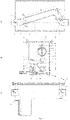
- the measuring fluid enters the flowmeter through an inlet connection 1 and continues to flow through a reaction tube 2, passing through the spherical coupling made of a nozzle (spherical calotte) 3 belonging to the inlet connection 1 and a nozzle (spherical calotte ) 4 belonging to the reaction tube 2.
- the fluid then passes through the reaction tube 2, which is bent at the other end by 90°, and terminates with a convergent nozzle.
- the fluid coming out of the reaction tube 2 is taken up by an outlet connection 5 through which it is discharged from the flowmeter.
- the outlet connection 5 takes over the fluid through a wide converging nozzle, so as not to disturb the reaction tube 2, at its very small functional rotation.
- connections 1 and 5 are fixed rigidly and tightly to the housing 6 of the flow meter, having their symmetry axes collinear, on the same horizontal.
- the bosses 7 are cylindrical, and are placed vertically, up and down around a vertical shaft 8 (according to Fig.2 ). In special situations, the bosses 7 can be replaced by a continuous circular crown along the inner circumference of the spherical calotte 4.
- the bosses 7 have a very small height and a small outer diameter, ensuring the decrease at minimum of the contact friction between the nozzle (spherical calotte 3) of the inlet connection 1 and the nozzle (spherical calotte 4) of the reaction tube 2.
- Rigorously concentric positioning of the two spherical calottes 3 and 4 is performed by a metal shaft 8.
- the spherical calotte 3 of the inlet connection 1 is provided with two circular holes positioned vertically, diametrically opposed, having a diameter a little larger than that of the shaft 8, to ensure the minimum play against it.
- the inlet connection 1 is rigidly mounted to the housing 6, so that the axis of the centers of the two holes is in a perfectly vertical position.
- the spherical calotte 4 of the reaction tube 2 is provided, at its upper part, with a circular hole having the same diameter as that of the two holes drilled diametrically opposite in the spherical calotte 3.
- the calotte 4 is provided with a clogged hole, having the same diameter as the three holes described above.
- the measuring shaft 11 of the torque transducer 12 being rigidly locked relative to the reaction tube 2 respectively to its outer boss with which it is provided at its lower part, takes over integrally the rotation torque of the tube 2.
- the housing 6 of the flowmeter is closed by a cover 17, which ensures the tightness of the flowmeter by tightening a gasket 18 with some screws 19 in the nuts 20.
- This torque (moment) of rotation is taken over by the measuring shaft 11 and implicitly by the torque transducer 12 whose output electrical signal, proportional to the measured mass flow rate, is taken over by an electronic block 21 through a cable 22, which is passed through the housing 6, through a stuffing box 23.
- thermosensor 24 Although the influence of temperature on the output signal of the torque sensor is very small (0.01 .... 0.015% FS / 0 C), to ensure a very high accuracy of flow measurement, also is provided a temperature sensor 24, whose output signal is transmitted via a cable 25 to the electronic block 21 to ensure temperature compensation of the torque sensor output signal.
- the torque transducer is immersed in the measuring fluid, its output signal being implicitly compensated with the temperature of the measuring fluid, measured by same sensor 24.
- the measuring shaft 11 of the torque transducer 12 functionally requires a very small angle of maximum torsion, of 0.2 0 ... 0.6 0 for the measurement of its maximum (nominal) torque, implicitly also the reaction tube, which is rigid with the measuring shaft 11, will have the same insignificant angle of rotation for crossing the entire flow measurement range (Qm,minim ... Q m,maxim ).
- this type of reaction flowmeter is practically considered as a flowmeter without moving parts.
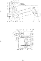
- Another embodiment of a nonlinear reaction flowmeter without moving parts is with the taking over by magnetic coupling and the measurement of the reaction torque outside the fluid ( Fig. 3a, b ).
- the measuring fluid enters in the flowmeter through an inlet connection 26 ending with a nozzle (spherical calotte) 27 which enters in a nozzle (spherical calotte) 28, afferent to a reaction tube 29.
- the fluid passes through the reaction tube 29, which is bent at the other end to 90 0 and terminates with a convergent nozzle.
- the fluid coming out of the reaction tube is taken up by an outlet connection 30, through which it is discharged from the flowmeter.
- the outlet connection 30 is provided at its inlet with a large convergent nozzle for taking up the fluid coming out of the reaction tube 29, this nozzle being thus designed not to disturb the reaction tube 29, at its very small rotation mentioned above.
- connections 26 and 30 are fixed rigidly and tightly to a housing 31 of the flowmeter, having the symmetry axes collinear on the same horizontal.
- the radial equidistance between the nozzle (spherical calotte) 27 afferent to the inlet connection 26 and the nozzle (spherical calotte) 28 afferent to the reaction tube 29 is achieved constructively through two bosses 32, afferent to the spherical calotte 28 of the reaction tube 29.
- the bosses 32 are cylindrical and are located vertically, up and down, around the vertical shaft 33.
- bosses 32 can be replaced with a continuous circular crown along the inner circumference of the spherical calotte 28.
- the bosses 32 having a very small height and a small outer diameter, ensure the decrease to minimum of the contact friction between the inlet connection 26 and the reaction tube 29.
- the shaft 33 passes both through the two circular positioning holes, with which the spherical calotte 28 of the reaction tube 29 is provided, the holes being placed diametrically opposite in the vertical plane, and respectively through the two circular positioning holes, with which is provided the spherical calotte 27 of the inlet connection 26, the holes being placed diametrically opposite in the same vertical plane.
- the tolerances of the diameters of the two positioning holes of the spherical calotte 27 ensure minimum clearances between it and the vertical shaft 33.
- the vertical shaft 33 is stiffened relative to the reaction tube 29, respectively to its spherical calotte 28, by a locking system consisting by screw 34-nut 35.
- the shaft 33 rests on a flange with collar 39, which is stiffened both to the support 38 by a system screw 40-nut 41 and to a housing 31 of the flowmeter by some screws 42.
- a wheel or only a circular sector with a very small angular opening
- a driving wheel having a large diameter
- a wheel 44 with the role of a driven wheel, having a smaller diameter
- a circular magnet 46 On a shaft 45 of the driven wheel 44 is placed rigidly a circular magnet 46, diametrically polarized.
- the shaft 45 can be rotated relative to the support 38, being rigidly fixed to the moving parts of some bearings 47 and 48. These bearings are fixed on the support 38 by tightening some pieces 49 and 50 with some systems screw 51 - nut 52 and respectively screw 53-nut 54.
- a magnet 46 which is immersed in the measuring fluid, reproduces the rotation of the wheel 44 and by magnetic coupling determines the rotation of a magnet 55, which is placed outside the housing 31 of the flowmeter.
- the outer magnet 55 is also diametrically polarized like the inner magnet 46.
- the magnet 55 is rigidly fixed on a measuring shaft 56 of a torque transducer 57, being guided and rigorously positioned in a vertical position by a bearing 58, a bearing ensured through the passing hole itself, by the corresponding profiled extension of the outer wall of the housing 31 of the flowmeter.
- the housing 31 of the flow meter is closed by a cover 59 which ensures the tightness of the flowmeter by tightening a gasket 60 with a system of screws 61 - nuts 62.
- This torque (moment of the force) of rotation is taken up by the shaft 33, the angle of rotation of which is amplified by the gear between the two wheels 43 and 44.
- the rotation moment of the magnet 55 is measured by the torque transducer 57, because this magnet is rigidly mounted on the measuring shaft 56 of the transducer 57, causing its corresponding torsion.
- the output signal from the torque transducer 57 is transmitted to an electronic block 63.
- a third example of embodiment of a nonlinear reaction flowmeter without moving parts is the one with the measurement of the reaction force by the differential measurement of the pushing pressure it produces ( fig. 4a, b ).
- the radial equidistance between the nozzle (spherical calotte) 67, corresponding to the inlet connection 66 and the nozzle (spherical calotte) 68 related to the reaction tube 69, is achieved constructively through two bosses 72, corresponding to the spherical calotte 68 of the reaction tube 69.
- the bosses 72 are cylindrical and are placed vertically, up and down, around the vertical shaft 73.
- bosses 72 can be replaced with a continuous circular crown, along the inner circumference of the spherical calotte 68.
- the bosses 72 having a very small height and a small outer diameter, ensure the decreasing at minimum of the contact friction between the spherical calotte 67, corresponding to the inlet connection 66 and the spherical calotte 68, related to the reaction tube 69.
- reaction tube 69 A rigorous positioning of the reaction tube 69 relative to the inlet connection 66 is ensured by the rigorously concentric positioning of the spherical calottes 67 and 68, performed by means of a vertical shaft 73.
- the shaft 73 passes through both circular positioning holes, with which the spherical calotte 68 of the reaction tube 69 is provided, the holes being placed diametrically opposite in vertical plane, and through the two circular positioning holes, with which is provided the spherical calotte 67 of the inlet connection 66, holes placed in turn diametrically opposite, having the centers on the same vertical with the two previous positioning holes.
- the design tolerances of the diameters of the two positioning holes of the spherical calotte 67 ensure minimum clearances between the calotte 67 and the vertical shaft 73.
- the vertical shaft 73 is stiffened relatively to a lower outer boss 74 of the reaction tube 69, respectively to its spherical calotte 68, through a locking system screw75 - nut 76.
- the boss 74 is cylindrical and placed in the plane. vertical.
- the rigorous positioning of the shaft 73 both horizontally and vertically is achieved by providing two holes (bearings) 77 and 78 for its passage through the upper and lower walls of a support 79 of the reaction tube 69.
- the centers of two holes (bearings) 77 and 78 are rigorously placed on the same vertical, and thus constructively ensure both minimum horizontal clearance and minimum friction of the shaft 73.
- the shaft 73 rests on a flange with a collar 80 which is stiffened both relative to the support 79, by a system screw 81 - nut 82, and to the housing 71 of the flow meter, by some screws 83.
- the reaction tube 69 is provided at its entrance with two outer bosses 74 and 84 located vertically, and diametrically opposite.
- a pin 85 is rigidly embedded which, through its hemispherical end, is in permanent contact with a separating diaphragm 96 to which it permanently transmits the pushing force Fs, from the part of the reaction tube 69, as long as the fluid flows through it and implicitly the reaction force F R is generated.
- a pin 85 presses a separation membrane 86, through a part 87, which directly takes over the force Fs.
- the diaphragm 96 is tightly tightened between the part 87 and a nut 88, by fully screwing them. Thus, the diaphragm 86 takes over the force Fs.
- the separation diaphragm 96 is rigidly fixed to its outside, and sealed between some flanges 88 and 90 which are tightly together by a system of screws 91-nuts 92.
- connection 93 On the flange 88 is welded a nozzle 93 which passes through a hole 94 existing in the side wall of the support 79 and is stiffened against it by the complete screwing of a nut 95.
- the connection 93 is mounted rigidly and sealed against the housing 71 and connected to high pressure tap (+tap) 96 of a differential pressure sensor 97. Through the connection 93 is transmitted the pressure taken over on the other side of the separation diaphragm 96.
- connection 99 which is rigidly mounted and sealed to the housing 71.
- the sensor 97 ensures the fully rigorous measurement of the deferential pressure ⁇ p, being provided structurally and with the function of its compensation with the temperature of the measuring fluid.
- the output signal from the differential pressure sensor 97 is applied via a cable 100 to an electronic block 101.
- the electrical output signal from the electronic block 101 renders the value of the measured mass flow Q m . Since the pressure transmitting liquid from the separation diaphragm 86 to the pressure transducer 97 is practically incompressible, the displacement of the diaphragm 86, implicitly of the pin 85, is therefore particularly small, almost zero, for measuring the entire range Q min ?? Q max . By default, the displacement of the reaction tube 69 is also extremely small.
- reaction flowmeter without moving parts with the non-linear characteristic relationship is that of the reaction flowmeter with direct measurement of the output pushing force by its electromagnetic balancing- Fig.5a , b.
- the principle of the configuration of the reaction flowmeter is to ensure the indirect measurement of the reaction force F R by measuring its output pushing force Fo, which is proportional to it.
- the output pushing force Fo is measured by its electromagnetic balancing.
- the measuring fluid enters in the flowmeter through the inlet connection 102, terminated with a nozzle 103 which enters in a nozzle 104 of a reaction tube 105.
- the fluid flows through the reaction tube 105 and the convergent outlet nozzle 106, respectively, and is then taken up by a nozzle 107 of the outlet connection 108, being discharged from the flowmeter without turbulence.
- the input 102 and the output 108 connections are horizontal collinear connections and are rigidly and tightly fixed to the flowmeter housing 109.
- the reaction tube is provided with a shaft 110, perpendicular to it and rigid with it, by fixing it with the screw 111 and the nut 112.
- the shaft 110 rests on a support 113, stiffened in relation to a housing 109 by means of some screws 114.
- the housing 109 it is closed by the flowmeter cover 115 with the screw-nut system 116 which tightens the gasket 117.
- the rigorous positioning of the shaft 110 ensures, on the one hand, the rigorous concentric radial equidistance between the nozzles103 and 104 and, on the other hand, the insignificant friction with the upper bearing 118 and the lower bearing 119.
- the equidistance between the nozzles 103 and 104 is constructively achieved by two small inner bosses 120 of the nozzle 104 of the reaction tube, placed at the top and bottom of the vertical shaft 110.
- an insignificant friction, between the nozzles 103 and 104 which have a rigorous concentric positioning and, on the other hand, the mobility of the potential rotation of the reaction tube 105, relative to the vertical axis of the shaft 110, without any inconvenience.
- the reaction tube 105 is provided with the outer boss 121.
- a pin 122 is rigidly incorporated.
- the subassembly (pin 122 and magnet 123) can move freely relative to the closed tube 124.
- the tube 124 is welded to the housing 109, being a common part thereof.
- annular magnet 125 Outside the tube 124, around it is placed an annular magnet 125 with a free movement relative to the tube 124, having the inner hole with a larger diameter suitable relative to outer diameter of this.
- the magnet 125 is rigidly fixed to its support 126.
- the support is constructively fixed to the moving part of the force sensor 127 and permanently transmits it the pushing force, received by the magnet 125 (respectively by the inner magnet 123), with the instantaneous value Fo.
- the force sensor 127 which receives the pushing force Fo, at any very small tendency to move its moving part, (corresponding to any small variation of the force Fo), ensures its electromagnetic balancing, and at the same time measuring this force.
- the electrical output signal of the sensor 127 being proportional to the value of the measured force Fo, is applied to the electronic computing block 128.
- the outer ring magnet 125 together with its support 126, the force sensor 127 and the flow computing block 128, are properly positioned inside a awn housing 129, which is closed by the cover 130 with the screw and nut system 131, which tightens the gasket. 132
- the housing 129 is not in contact with the measured fluid, being rigidly fixed (for example by welding) to the housing 109, which, on the contrary, is permanently in contact with the fluid.
- the force sensor 127 is rigidly fixed to the housing 129, in a rigorous position, for to ensure its correct functional positioning in relation to the system of taking the pushing force, achieved by the magnetic coupling of the two magnets 123 and 125.
- the block 128 calculates the corresponding value of the reaction force F R , according to the known analytical relationship between the forces F R and Fo.
- block 128, where the calibration curve Q m Q m (F R ) was previously stored, ensures the calculation of the instantaneous value of the mass flow Q m compensated with T and P, the parameters measured by sensors 133 and 134, corresponding to the measured value of Fo (respectively F R ) and generates an electrical output signal, proportional to the respective measured value of Q m .
- the movement of the moving part of the sensor 127 and implicitly of the pin 122 is very small, corresponding to the measurement of the entire range Q m , min ... Q m, max of the reaction flowmeter.
- reaction tube 105 the displacement of the reaction tube 105 is very small and, consequently, this type of reaction flowmeter is considered without moving parts.
- a last example of realization of reaction flowmeter without moving parts, in individual configuration, is the one with direct measurement of the output force, with load cell with strain gauge.
- This type of reaction flowmeter has the same configuration as the that shown previously in Fig. 5a, b and the same mode of operation, with the difference that the item 127 is a load cell with strain gauge and not one with force measurement by its electromagnetic balancing, the rest of the operation being identical.
- the mass flow rate Q m determines the generation of a reaction force F R , which tends to rotate the reaction tube 136 about the shaft 137, the arm of the force F R being L R .
- connections 135 and 138 are fixed rigidly and Q m the housing 139 of the flow meter, the connections 135 and 138 are fixed rigidly and tightly sealed.
- the reaction tube 136 is rotated by it.
- the shaft 137 being rigid with the reactance tube 136, rotates at an angle a, together with the magnet 140, which is stiffened with respect to the shaft 137 of the bush 141.
- the magnet 142 inside the housing 139 of the flowmeter determines, by magnetic coupling, the rotation with the same angle ⁇ of the outer magnet 142, which is located outside the housing 139, being rigidly mounted to the inner ring of the bearing with bearing 143.
- the bearing 143 is rigidly mounted on the housing 139.
- the helical spring 144 is fixed with one end to its support 145, and with the other end to the rod of the circular sector 146, which in turn is fixed rigidly, by gluing, on the outer magnet 142, thus rotating in turn with the angle ⁇ .
- the radial resistive arm 149 is rigidly fixed to the roller 147, arm which is a rod made of electrically insulating material on which is uniformly wound an electrical resistance made of a wire with very high resistivity which is practically not influenced by the variation of ambient temperature (e.g. kanthal, manganine etc.).
- the cam 150 is rigidly placed on the cover of the housing 139 and has an electrical conductor 151 fixed to its entire outer contour. he radial resistive arm 149, is in permanent contact with the conductor 151, the contact point being the one corresponding to the length R of the cam radius, length corresponding to the value of the rotation angle ⁇ .
- the value of the electrical resistance R E ( ⁇ ) of the resistive arm 149, corresponding to the rotation angle ⁇ is determined as being between its central point (denoted by A) and the point B of contact with the electrical conductor 151, afferent to the radius R ( ⁇ ) corresponding to the angle ⁇ .
- the electrical resistance RE ( ⁇ ) between points A and C is detected by the electronic block 152, point C being one end of the electrical conductor 151, and the electrical equivalent of point B.
- Fig. 7 an example of embodiment of the bypass type reaction flowmeter is shown in Fig. 7 , consisting in the placement in bypass montage of two pipes, respectively the main pipe 153 and the secondary pipe 154.
- a fluidic resistance 155 (achieved by an orifice plate, nozzle, or short Venturi tube).
- the secondary pipe 154 Through the secondary pipe 154 (with small diameter) is taken the flow rate q m , of a small value, from the total flow rate Q m , with high value, the inlet flow rate in the main pipe 153 (with large diameter).
- this configuration ensures the determination, by computing, and implicitly the measurement of the total flow rate Q m , by the effective measurement only of the secondary flow rate q m by the reaction flowmeter 156, placed on the secondary pipe 154.
- the reaction flowmeter 156 can be achieved in any of the construction variants indicated above.
- the flowmeter As the claimed method, called the 'extended flow measurement method', the flowmeter, called the 'extended reaction flowmeter', ensures, through its configuration, the functional and implicitly constructive correlation between the two reaction flowmeters that make it up.
- the extended flowmeter consists of a specific coupling of a "main flowmeter” with a “secondary flowmeter”, having their flow ranges with correlated values, according to the provisions of this method.
- the measured flow rate Q enters in the extended reaction flowmeter through its inlet connection 157, consisting of the inlet connection 158 of the jet diverter 159, placed at the inlet of the flowmeter.
- the jet divider 159 being actuated by its solenoid 160, switches the flow of the incoming fluid, either at the outlet 161, to the "main flowmeter” (corresponding to position I of the diverter), or at the outlet 162, to the “secondary flowmeter” (corresponding to position II of deviator) and vice versa, according to the order received from the electronic block 163.
- the 'main flowmeter' consists of the immobile inlet tube 164, the reaction tube 165 that generates the reaction force and the exhaust tube 166.
- the main reaction tube 165 is provided with the shaft 167, which is perpendicular to it and rigid with respect to it, ensuring the possibility of rotating the tube 165 with respect to the vertical axis of the shaft.
- the reaction force F RM generated by the reaction tube 165, acts along the axis of this elbow at a distance L M to the axis of the shaft.
- the main reaction tube 165 is provided with boss 168.
- the pin 169 is rigidly incorporated.
- the magnet 170 At the end of the pin 169 is rigidly fixed the magnet 170, which is implicitly positioned inside a small closed tube. 171.
- the assembly formed by the pin169 and the magnet 170 has the possibility to move relative to the closed tube 171, which is configured as part of the housing 172, of the extended reaction flowmeter.
- annular magnet 173 which can move freely relative to it, its central hole having a corresponding diameter larger than the outer diameter of the tube 171.
- the magnet 173 is rigidly fixed to its support 174 which, in turn, is constructively fixed to the moving part of the force sensor 175, permanently transmitting to it the pushing force Fo, received by magnetic coupling from the magnet 170.
- the value of the pushing force Fo,of output from the flowmeter, is proportional to the reaction force F RM .
- the force sensor 175 receives the output pushing force F 0 (with the value F 0 I correspondin g to the position I of the jet diverter 159) and according to its principle of operation, at any very small tendency of displacement of its moving part (corresponding to a small variation of force F 0 I ), ensures electromagnetic balancing and its measurement at the same time. Consequently, the electrical output signal of the force sensor 175 is proportional to the value of the pushing force F 0 I and is applied to the electronic block 163.
- the ring magnet 173, its support 174, the force sensor 175 and the electronic block 163 are properly positioned in the outer box of the extended reaction flowmeter, which has its own housing 176, which is closed by the cover 177 with the screw-nut system 178, by tightening the gasket 179.
- the housing 176 is not in contact with the measured fluid being rigidly fixed to the housing 172 of the flowmeter, which, on the contrary, is permanently in contact with the measured fluid.
- the force sensor 175 is rigidly fixed to the housing 176, in a corresponding position relative to the system for receiving the pushing force, ensuring its rigorous measurement.
- the QM flow rate is compensated with the pressure P and the temperature T, the parameters measured by sensors 179 and 180.
- the electronic block 163 performs its second function of controlling and switching the position of the diverter 159, according to the algorithm of ensuring the operation of the extended reaction flowmeter, respecting the functional correlations presented in table 1 below:
- Table 1 The value of the measured flow Q Jet diverter status Q Smin ______Q Mmin Position II Q Smax ______Q Mmax Position I Q Mmin ⁇ (Only for the upward tendency of the flow rate) Switching from Position II to Position I Q Smax ⁇ (Only for the downward tendency of the flow rate) Switch from Position I to Position II
- the electronic block 163 calculates, on the one hand, the instantaneous value of the measured flow rate Q and, on the other hand, according to this value commands the position of the diverter 159.
- the entire flow range Q Smin ... Q Mmax , which is marked with a thickened line in the diagram, corresponding to the extended reaction flowmeter.
- the overlapping zone ⁇ Q of the ranges of the two component flowmeters practically completely covers the switching inertia zone of the diverter 159, achieving both the continuity of the flow measurement over the entire range of the flowmeter, including the overlapping zone ⁇ Q, nd a moderate value of measurement error for this zone, with a value of up to 50% of the maximum value of the E max error, respectively: E switching , max % o .r . 0.5 ⁇ Emax % o .r .
- the block 163 will keep the diverter 159 in position I, only when the measured flow rate values by the "main flowmeter” fall within the range Q Mmax ... Q Smax .
- the electronic block 163 commands the switching of the diverter 159 from its initial position I to position II, and now the introduced fluid is directed to flow only through the "secondary flowmeter", the flow measurement being continued only by this.
- the 'secondary flowmeter' consists of the immobile inlet tube 181, the reaction tube 182 and the exhaust tube 183.
- the fluid discharge tubes 166 and 183 are constructively jointed into a single piece which constitutes the output connection of the extended reaction flowmeter.
- the secondary reaction tube 182 is provided with the vertical shaft 183, which ensures the potential rotation mobility of the tube relative to the shaft axis.
- the pin 185 is rigidly incorporated in this boss, at a distance L 1 from the shaft axis.
- the relative positioning between the main reaction tube 165 and the secondary reaction tube 182 is performed constructively, so that the pin 185 is in permanent contact with the main reaction tube 165 and pushes it with the force Fs, for as long as the diverter 159 it is in position II, and the flow measurement is performed by the "secondary flowmeter".
- the pushing force F 0 II is proportional to the force Fs and implicitly to the measured flow QS .
- the output signal of the sensor 175 is applied to block 163 which, on the one hand, calculates the value of the instantaneous flow rate Qs (compensated with P and T) and, on the other hand, controls the position of the diverter 159, according to the algorithm shown in table 1, respectively:
- Another example of embodiment the extended reaction flowmeter is the one with the differential measurement of the pushing output force, presented in Fig.9 .
- the essential difference compared to the previous example, consists in the method of measuring the output pushing force and implicitly in the system of taking over of force.
- the entered fluid through the connection 186 of the diverter 187 is switched by the diverter, either to its outlet 189, to the "main flowmeter” (corresponding to position I of the diverter), or to its outlet 190 to “secondary flowmeter” (corresponding to the position II of the diverter) and vice versa, depending on the order received from the electronic block 191.
- a first essential difference consists in the way of taking the force F 0 I from the pin 192.
- the pressure po to which is permanently added the static pressure pf of the measured fluid, is taken over by the transmission liquid, which completely fills the connection 194, and their sum is applied to the high-pressure inlet of the ⁇ p sensor, 195.
- the senor 195 ensures the differential measurement of the pushing pressure po, respectively its compensation with the temperature and pressure of the measured fluid, the sensor being provided with this additional function.
- the output signal of the sensor 195 which shows the value of the pushing pressure p, is applied to the electronic block 191.
- block 191 will keep the diverter 187 in position I, only when the flow rate values Q M , measured with the "main flowmeter”, fall within the range (Q Mmax ... Q Smax ).
- the electronic block 191 commands the switching of the diverter 187 from its initial position I to position II and now the entered fluid is directed to flow only through the "secondary flowmeter", the flow measurement being continued only by it.
- the shaft of the secondary reaction tube 197 is functionally positioned to the right of the shaft 198 of the main reaction tube 199, at a distance L A .
- the pin 201 is fixed on the boss 200, at a distance L 1 from the axis of the rotating shaft of the tube 197.
- the relative positioning between the main reaction tube 202 and the secondary reaction tube 197 is performed constructively, so that the pin 201 to be in permanent contact with the main reaction tube 202 and to push it with force Fs for as long as the diverter 187 is in position II, and the flow measurement is provided by the secondary flowmeter.
- the ⁇ p sensor 195 and the electronic block 191 are placed inside a box 203, tightly closed with the lid 204, not being in contact with the measuring fluid and being rigidly fixed on the housing 199, which is in permanent contact with the measuring fluid.
- the electronic block 191 controls the position of the diverter 187, as follows:
Landscapes
- Physics & Mathematics (AREA)
- Fluid Mechanics (AREA)
- General Physics & Mathematics (AREA)
- Measuring Volume Flow (AREA)
Abstract
Description
- The subject matter of this invention is defining and applying of new technical solutions for flow measurement by using devices consisting of individual, bypass or extended reaction flowmeters without moving parts usable in measuring the flow rate of any fluid (liquids, gases, steam), for extensive measuring ranges of them, correlated with an optimal measurement accuracy and with ensuring low cost acquisition, installation and maintenance, due to the simplicity configuration of the fluid flow path through the flowmeter.
- It is known from the European Patent
EP 3364159 B1 a computer- implemented method for unitary synthesis and design of flowmeters and of compound gauging structures, whose algorithm allows the configuration of practically any new type of flowmeter and combination of flowmeters, and already confirmed by all currently known solutions, by successive interconnection, according to an original matrix of logical criteria, of some original basic functional blocks, identified by the author. - The presented method has the advantage that it allowed the substantiation and definition of a new category of flow meters, called with reaction, but however being a theoretical method, it has the disadvantage that it cannot present a concrete constructive structure of these types of flow meters..
- From the patent application
RO 133994 A2 - Disadvantages of the reaction flowmeters solutions with moving parts, as indicated in the state of the art, consist in a higher complexity of the achievement and joining of the flowmeter components and implicitly in the increase of the realization and use costs of these types of flowmeters.
- In addition, the existence of some moving parts leads, through this principle constructive solution, to the decrease of the life duration of the flowmeter as a whole.
- From patent document
EP 19020006 - However, the solutions presented do not exhaust the functional and constructive possibilities of flow meters without moving parts and, in addition, have limits in ensuring the maximization of the value of the ratio between the maximum flow and the minimum flow measured by the flowmeter, optimally correlated with the minimization of the variation interval of the maximum permissible values of measurement error of its.
- In addition, present solutions do not offer the possibility to extend the measuring ranges of the flow meters, with related implications regarding the improvement of the measurement accuracy. Technical problem solved by the present invention consists in defining of new types and variants of flow meters without moving parts, both based on a nonlinear relationship between the flow rate and their output parameter, when the generated reaction force is used as output parameter by being measured consequently, completed by individual or coupled correlated configurations, as well as on a linear relationship between the flow rate and their output parameter, by nonlinear translation of the reaction force into another parameter, which becomes the output parameter of the flowmeter, thus resulting in its linear dependence on flow rate.
- Thus, it is ensured a functional optimum, by increasing the value of the ratio between the maximum flow rate and the minimum flow rate measured by the flowmeter, corresponding to an optimal range of accuracy values, rendered by the maximum permissible values of its measurement error.
- The reaction flow meters according to this invention, are considered without moving parts, because functionally they involve an angular displacement of the reaction tube practically insignificant (generally only 0.2° ...... 0.6°).
- The reaction flowmeters without moving parts according to this invention, are constituted, in individual structure, of a Primary Element consisting of the connection between a Reference Block BR, made in the form of a fixed horizontal access tube, and a Sensitive Block BS made as a curved quasi-immobile tube, and an ES Sensitive Element, made, either as the sensor of the moment of force, or as a differential pressure sensor, or as a force sensor.
- This curved quasi-immobile tube is called, according to the invention, immobile reaction element, and the flowmeter made on the basis of the method in this configuration, is called reaction flowmeter without moving parts.
- These reaction flowmeters, in individual configuration, use a non-linear functional dependence between the measured mass flow rate Qm and the reaction force FR which it generates on a reaction element, materialized by 'the reaction tube', which practically remains immobile during the measurement of the mass flow rate.
- Depending on the sensor type and on the measurement mode of the FR force, the flowmeter without moving parts, which uses as output parameter the FR force, which varies nonlinearly with the flow rate, is achievable with the measurement of the FR force, with differential measurement of FR (with a Δp sensor), and with direct measurement of the FR force, in two distinct functional solutions, respectively, by an electromagnetic balancing of FR or with a load cell with a sensor strain gauge type.
- The reaction flowmeter according to the invention also considers a technical solution having the linear dependence "t output parameter obtained by the non-linear transformation of the reaction force FR - measured flow rate", achieved by means of a cam which ensures the nonlinear transformation of the force FR in output parameter, so that the dependence between the output parameter and the measured flow rate Qm is linearized.
- Another configuration regarding the reaction flowmeters without moving parts, is of bypass type, with nonlinear dependence "output parameter - measured flow rate".
- This solution provides the placement of a reaction flowmeter without moving parts on a secondary conduit, in parallel with a main conduit provided with a fluidic resistance. The secondary conduit has a significantly smaller diameter than that of the main conduit.
- By establishing the relationship between the fluid flows rates passing through the two conduits, this configuration ensures, by an effective measurement of a small secondary flow rate by the afferent reaction flowmeter, the determination by computing of the total measured flow rate.
- A last solution is rendered by a configuration in the form of a special connection and functional correlation, between two nonlinear reaction flowmeters, which have the two flow measurement ranges thus correlated that, the values of one are a continuation of the other, with a very small overlap between them.
- According to the previously stored algorithm, an electronic block of the flowmeter controls the switching, by using a jet diverter, of the fluid flow through the main flowmeter, corresponding to the branch with the larger diameter, or through the secondary flowmeter corresponding to the branch with smaller diameter.
- In this way, is achieved a significant extension of the total flow measurement range of this type of flowmeters and, consequently, these flowmeters are called "extended reaction flowmeters".
- Further are presented several examples of embodiments of reaction flowmeter without moving parts, with reference also to
figures 1-9 , which represent: -
Fig.1 - Basic (principled) scheme of a reaction flowmeter: a) -in individual configuration with nonlinear dependence output parameter - measured flow rate; b) -in individual configuration with linear dependence output parameter - measured flow rate; c) -in bypass configuration; d) - in extended configuration; -
Fig.2 - Reaction flowmeter with direct measurement, in fluid, of the reaction torque: a) longitudinal section; b) section with a plane A-A; c) side view; -
Fig.3 -Reaction flowmeter with taking over by magnetic coupling and measuring of reaction torque outside the fluid: a) longitudinal section; b) section with a plane A-A; -
Fig.4 - Reaction flowmeter with measurement of the reaction force, by the differential measurement of the pressing pressure which it produces: a) longitudinal section; b) section with a plane A-A; -
Fig.5 - Reaction flowmeter with the measurement of the reaction force by electromagnetic balancing: a) longitudinal section; b) section with a plane A-A; -
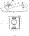
Fig.6 - Reaction flowmeter with linear dependence between the output parameter and the measured flow rate: a) horizontal longitudinal section; b) section with a plane A-A; c) top view; -
Fig.7 - Structural scheme bypass type reaction flowmeter; -
Fig.8 - Reaction flowmeter in extended structure, with the measurement of the output pushing force, by electromagnetic balancing; -
Fig.9 - Reaction flowmeter in extended structure, with differential measurement of the output pushing force; - Making reference to to
Fig.1 a , the reaction flowmeter without moving parts, according to invention, is constituted, in the individual structure, of a Primary Element that consists of the association between a BR reference block, achieved in the form of a fixed horizontal access tube, and a Sensitive block BS made as a quasi-immobile curved tube, and respectively a Sensitive Element ES, achieved, either as a sensor of force moment, or as a differential pressure sensor, or as a force sensor. - The quasi-immobile curved tube is called, according to the invention, immobile reaction element, and the flowmeter achieved on the basis of the method in this configuration, is called reaction flowmeter without moving parts.
- These reaction flowmeters, in individual configuration, use a non-linear functional dependence between the measured mass flow rate Qm and the reaction force FR that this generates on a reaction element, materialized by the "reaction tube", which remains practically immobile during the measurement of mass flow rate, according to the relationship:

- FR - reaction force (measured parameter, used as output parameter of the flowmeter);
- Qm - measured mass flow rate (input parameter of the flowmeter);
- k - constant;
- p -density of the measured fluid.
- According to the invention, depending on the type of sensor and of the measurement mode of force FR, the flowmeter without moving parts, which uses force FR as output parameter, which non-linearly varies with flow rate, is achievable with moment measurement of force FR, with differential measurement of FR, by means of a Δp sensor, and with direct measurement of force FR, in two distinct functional solutions respectively, by electromagnetic balancing of FR, or with a load cell with a sensor strain gauge type.
- The reaction flowmeter according to the invention, also considers a technical solution having the linear relationship of dependence" output parameter obtained by the non-linear transformation of the reaction force FR - measured flow rate", achieved by means of a cam, used for nonlinear transformation of the force FR - in output parameter XI = FR 1/2.
- Thus, the dependence between the output parameter XI and the measured flow rate Qm is linear respectively according to the relationship:

- Another configuration regarding the flow meters with reaction without moving parts, is of a bypass type, with nonlinear dependence "output parameter - measured flow". This solution provides the placement of a reaction flowmeter without moving parts on a secondary conduit, in parallel with a main conduit provided with a fluid resistance. The secondary conduit has a significantly smaller diameter than that of the main conduit.
- By establishing in advance the relationship between the fluid flow rates passing through the two conduits, this configuration ensures, by an effective measurement only of a small secondary flow by the corresponding reaction flow meter, the determination by computing of the total measured flow rate.
- A last solution is given by a configuration in the form of a special functional connection and correlation, between two nonlinear reaction flowmeters, which have the two flow measurement ranges thus correlated that, the values of one are in continuation of the other, with a very small overlap between they.
- According to the previously stored algorithm, an electronic block of the flowmeter controls the switching, with a jet deflector, of the fluid flow through the main flowmeter, corresponding to the large diameter branch or through the secondary flowmeter related to the small diameter branch.
- In this way, a significant extension of the total flow measurement range of this type of flowmeter is achieved and, consequently, these flowmeters are called "extended reaction flow meters".
- A first example of embodiment of the flowmeter without moving parts, based on a non-linear functional relationship of dependence between the reaction force and the flow rate, considers a reaction flowmeter with direct measurement in fluid of the reaction torque (
Fig. 2a, b, c ). - The measuring fluid enters the flowmeter through an
inlet connection 1 and continues to flow through areaction tube 2, passing through the spherical coupling made of a nozzle (spherical calotte) 3 belonging to theinlet connection 1 and a nozzle (spherical calotte ) 4 belonging to thereaction tube 2. - The fluid then passes through the
reaction tube 2, which is bent at the other end by 90°, and terminates with a convergent nozzle. The fluid coming out of thereaction tube 2 is taken up by anoutlet connection 5 through which it is discharged from the flowmeter. - The
outlet connection 5 takes over the fluid through a wide converging nozzle, so as not to disturb thereaction tube 2, at its very small functional rotation. - The
connections - The radial equidistance between the nozzle (spherical calotte) 3 of output from the
inlet connection 1 and the nozzle (spherical calotte) 4 of entry into thereaction tube 2 is constructively made by twobosses 7 corresponding to thespherical calotte 4 of thereaction tube 2. - The
bosses 7 are cylindrical, and are placed vertically, up and down around a vertical shaft 8 (according toFig.2 ). In special situations, thebosses 7 can be replaced by a continuous circular crown along the inner circumference of thespherical calotte 4. - The
bosses 7 have a very small height and a small outer diameter, ensuring the decrease at minimum of the contact friction between the nozzle (spherical calotte 3) of theinlet connection 1 and the nozzle (spherical calotte 4) of thereaction tube 2. - Rigorously concentric positioning of the two
spherical calottes metal shaft 8. - The
spherical calotte 3 of theinlet connection 1 is provided with two circular holes positioned vertically, diametrically opposed, having a diameter a little larger than that of theshaft 8, to ensure the minimum play against it. - The
inlet connection 1 is rigidly mounted to the housing 6, so that the axis of the centers of the two holes is in a perfectly vertical position. - The
spherical calotte 4 of thereaction tube 2 is provided, at its upper part, with a circular hole having the same diameter as that of the two holes drilled diametrically opposite in thespherical calotte 3. - Diametrically opposite this hole, the
calotte 4 is provided with a clogged hole, having the same diameter as the three holes described above. - Rigorous positioning of the
reaction tube 2 against to theinlet connection 1 is ensured by rigorously centric positioning of thespherical calottes calotte 3 with theshaft 8. - In this situation the
shaft 8 passes easily through this hole as well as through the other hole existing in thecalotte 3, at its lower part and diametrically opposed to the upper hole, the shaft finally occupying completely the clogged hole existing in the lower part of thecalotte 4 of thereaction tube 2. - According to
Fig. 3 , the spatial positioning (x, y, z) between the twocalottes reaction tube 2, the permanent locking of theshaft 8 in this position is ensured. - By means of a
wedge 10, the measuringshaft 11 of thetorque transducer 12 being rigidly locked relative to thereaction tube 2 respectively to its outer boss with which it is provided at its lower part, takes over integrally the rotation torque of thetube 2. - The correct measurement of this torque is ensured by locking the rotation of a
torque transducer 12, by locking itssupport shaft 13, relative to the housing 6 of the flowmeter with awedge 14, positioned between it and thesupport 15 which, in turn, is rigidly fixed to the housing 6 by means ofscrews 16. - The housing 6 of the flowmeter is closed by a
cover 17, which ensures the tightness of the flowmeter by tightening agasket 18 with somescrews 19 in the nuts 20. - Functionally, the reaction force FR developed by the flow Qm, at the exit from of the reaction tube, determines the torque (moment) MR = FR × LR which, in turn, reproduces the variation of Qm.
- This torque (moment) of rotation is taken over by the measuring
shaft 11 and implicitly by thetorque transducer 12 whose output electrical signal, proportional to the measured mass flow rate, is taken over by anelectronic block 21 through acable 22, which is passed through the housing 6, through astuffing box 23. - Although the influence of temperature on the output signal of the torque sensor is very small (0.01 .... 0.015% FS / 0 C), to ensure a very high accuracy of flow measurement, also is provided a
temperature sensor 24, whose output signal is transmitted via acable 25 to theelectronic block 21 to ensure temperature compensation of the torque sensor output signal. - The torque transducer is immersed in the measuring fluid, its output signal being implicitly compensated with the temperature of the measuring fluid, measured by
same sensor 24. - In the
electronic block 21 is stored previously, following the experimental calibration on the rig of the reaction flowmeter, its specific correspondence M = M (Qm) between the torque measured by thetransducer 12 and the flow rate Qm passed accordingly through the flowmeter. - Thus the output signal from the
electronic block 21 renders the value of the mass flow rate Qm. - Since the measuring
shaft 11 of thetorque transducer 12 functionally requires a very small angle of maximum torsion, of 0.20 ... 0.60 for the measurement of its maximum (nominal) torque, implicitly also the reaction tube, which is rigid with the measuringshaft 11, will have the same insignificant angle of rotation for crossing the entire flow measurement range (Qm,minim ... Qm,maxim). - Consequently, because from functional point of view the rotation angle of the reaction tube is practically insignificant, this type of reaction flowmeter is practically considered as a flowmeter without moving parts.
- Another embodiment of a nonlinear reaction flowmeter without moving parts is with the taking over by magnetic coupling and the measurement of the reaction torque outside the fluid (
Fig. 3a, b ). - The measuring fluid enters in the flowmeter through an
inlet connection 26 ending with a nozzle (spherical calotte) 27 which enters in a nozzle (spherical calotte) 28, afferent to areaction tube 29. - Then the fluid passes through the
reaction tube 29, which is bent at the other end to 900 and terminates with a convergent nozzle. - The fluid coming out of the reaction tube is taken up by an
outlet connection 30, through which it is discharged from the flowmeter. - The
outlet connection 30 is provided at its inlet with a large convergent nozzle for taking up the fluid coming out of thereaction tube 29, this nozzle being thus designed not to disturb thereaction tube 29, at its very small rotation mentioned above. - The
connections housing 31 of the flowmeter, having the symmetry axes collinear on the same horizontal. - The radial equidistance between the nozzle (spherical calotte) 27 afferent to the
inlet connection 26 and the nozzle (spherical calotte) 28 afferent to thereaction tube 29 is achieved constructively through twobosses 32, afferent to thespherical calotte 28 of thereaction tube 29. - The
bosses 32 are cylindrical and are located vertically, up and down, around thevertical shaft 33. - In special situations the
bosses 32 can be replaced with a continuous circular crown along the inner circumference of thespherical calotte 28. - The
bosses 32, having a very small height and a small outer diameter, ensure the decrease to minimum of the contact friction between theinlet connection 26 and thereaction tube 29. - Rigorous positioning of the
reaction tube 29 relative to theinlet connection 26 is ensured by rigorously concentric positioning of the spherical calottes 27 and 28, achieved by means of avertical shaft 33. - The
shaft 33 passes both through the two circular positioning holes, with which thespherical calotte 28 of thereaction tube 29 is provided, the holes being placed diametrically opposite in the vertical plane, and respectively through the two circular positioning holes, with which is provided thespherical calotte 27 of theinlet connection 26, the holes being placed diametrically opposite in the same vertical plane. - The tolerances of the diameters of the two positioning holes of the
spherical calotte 27 ensure minimum clearances between it and thevertical shaft 33. - In turn, the
vertical shaft 33 is stiffened relative to thereaction tube 29, respectively to itsspherical calotte 28, by a locking system consisting by screw 34-nut 35. - The rigorous positioning, both horizontally and vertically of the
shaft 33, is achieved by providing two holes (bearings) 36 and 37 for its passage through the upper and lower walls of asupport 38 of thereaction tube 29. - The centers of the two holes( with a bearing role) 36 and 37 are rigorously placed on the same vertical and thus constructively is ensured both minimum horizontal clearance and minimum friction of the
shaft 33. - The
shaft 33 rests on a flange withcollar 39, which is stiffened both to thesupport 38 by a system screw 40-nut 41 and to ahousing 31 of the flowmeter by somescrews 42. - On the upper end of the
shaft 33 is rigidly placed a wheel (or only a circular sector with a very small angular opening) 43, with the role of a driving wheel, having a large diameter, which is coupled by friction (or by a fin gear) with awheel 44, with the role of a driven wheel, having a smaller diameter. - Thus is ensures a transmission ratio, which ensures the corresponding multiplication of the rotation angle of the driven
wheel 44 to the very small rotation angle of thedriving wheel 43. - On a
shaft 45 of the drivenwheel 44 is placed rigidly acircular magnet 46, diametrically polarized. Theshaft 45 can be rotated relative to thesupport 38, being rigidly fixed to the moving parts of somebearings support 38 by tightening somepieces - A
magnet 46, which is immersed in the measuring fluid, reproduces the rotation of thewheel 44 and by magnetic coupling determines the rotation of amagnet 55, which is placed outside thehousing 31 of the flowmeter. - The
outer magnet 55 is also diametrically polarized like theinner magnet 46. - The
magnet 55 is rigidly fixed on a measuringshaft 56 of atorque transducer 57, being guided and rigorously positioned in a vertical position by abearing 58, a bearing ensured through the passing hole itself, by the corresponding profiled extension of the outer wall of thehousing 31 of the flowmeter. - The
housing 31 of the flow meter is closed by acover 59 which ensures the tightness of the flowmeter by tightening agasket 60 with a system of screws 61 - nuts 62. - Functionally, the reaction force FR developed by the flow rate Qm, at the outlet of the
reaction tube 29, determines the torque (moment) MR = FR x LR which thus renders the variation of the mass flow rate Qm. - This torque (moment of the force) of rotation is taken up by the
shaft 33, the angle of rotation of which is amplified by the gear between the twowheels - The rotation moment of the
magnet 55 is measured by thetorque transducer 57, because this magnet is rigidly mounted on the measuringshaft 56 of thetransducer 57, causing its corresponding torsion. - The output signal from the
torque transducer 57 is transmitted to anelectronic block 63. - Although the influence of temperature on the output signal of the torque transducer is very small, in order to ensure a very high accuracy of flow measurement, it is provided the placement of a
temperature sensor 64 next to thetorque transducer 57, outside thehousing 31, whose output signal is transmitted to theelectronic block 63 by acable 65, thus ensuring the temperature compensation of the output signal of thetorque transducer 57. - In the
electronic block 63 is stored previously, following the experimental calibration on the rig of the reaction flowmeter, its specific correspondence M = M (Qm), between the torque measured by thetransducer 57 and the flow rate Qm correspondingly passed through the flowmeter. Consequently, the electrical output signal fromblock 57 is proportional to the measured mass flow. - Since the maximum torsion angle of the torque transducer measuring shaft, respectively the angle required to measure the maximum torque value is very small (0.20 .... 0.60), and the reduction ratio achieved by the coupling of the two
wheels wheels reaction tube 29, it results that thereaction tube 29, functionally requires a very small rotation angle to cover the entire measuring range Qm,minim ...-Qm,maxim. - Consequently, this type of reaction flowmeter is practically a flow meter without moving parts.
- A third example of embodiment of a nonlinear reaction flowmeter without moving parts, is the one with the measurement of the reaction force by the differential measurement of the pushing pressure it produces (
fig. 4a, b ). - The radial equidistance between the nozzle (spherical calotte) 67, corresponding to the inlet connection 66 and the nozzle (spherical calotte) 68 related to the
reaction tube 69, is achieved constructively through twobosses 72, corresponding to thespherical calotte 68 of thereaction tube 69. - The
bosses 72 are cylindrical and are placed vertically, up and down, around thevertical shaft 73. - In special situations, the
bosses 72 can be replaced with a continuous circular crown, along the inner circumference of thespherical calotte 68. - The
bosses 72, having a very small height and a small outer diameter, ensure the decreasing at minimum of the contact friction between thespherical calotte 67, corresponding to the inlet connection 66 and thespherical calotte 68, related to thereaction tube 69. - A rigorous positioning of the
reaction tube 69 relative to the inlet connection 66 is ensured by the rigorously concentric positioning of the spherical calottes 67 and 68, performed by means of avertical shaft 73. - The
shaft 73 passes through both circular positioning holes, with which thespherical calotte 68 of thereaction tube 69 is provided, the holes being placed diametrically opposite in vertical plane, and through the two circular positioning holes, with which is provided thespherical calotte 67 of the inlet connection 66, holes placed in turn diametrically opposite, having the centers on the same vertical with the two previous positioning holes. - The design tolerances of the diameters of the two positioning holes of the
spherical calotte 67 ensure minimum clearances between the calotte 67 and thevertical shaft 73. - In its turn, the
vertical shaft 73 is stiffened relatively to a lowerouter boss 74 of thereaction tube 69, respectively to itsspherical calotte 68, through a locking system screw75 -nut 76. Theboss 74 is cylindrical and placed in the plane. vertical. - The rigorous positioning of the
shaft 73 both horizontally and vertically, is achieved by providing two holes (bearings) 77 and 78 for its passage through the upper and lower walls of asupport 79 of the reaction tube 69.The centers of two holes (bearings) 77 and 78 are rigorously placed on the same vertical, and thus constructively ensure both minimum horizontal clearance and minimum friction of theshaft 73. - The
shaft 73 rests on a flange with acollar 80 which is stiffened both relative to thesupport 79, by a system screw 81 -nut 82, and to thehousing 71 of the flow meter, by somescrews 83. - In order to stiffen the
reaction tube 69 with theshaft 73, thereaction tube 69 is provided at its entrance with twoouter bosses - In an upper
outer boss 84, at a distance Ls from the center of theshaft 73, apin 85 is rigidly embedded which, through its hemispherical end, is in permanent contact with a separatingdiaphragm 96 to which it permanently transmits the pushing force Fs, from the part of thereaction tube 69, as long as the fluid flows through it and implicitly the reaction force FR is generated. - Since constructively the LR / Ls ratio of the arms of the FR and Fs forces is higher than1, it results that the force Fs has an amplified value compared to the value of the reaction force FR.
- A
pin 85 presses aseparation membrane 86, through apart 87, which directly takes over the force Fs. Thediaphragm 96 is tightly tightened between thepart 87 and anut 88, by fully screwing them. Thus, thediaphragm 86 takes over the force Fs. - The
separation diaphragm 96 is rigidly fixed to its outside, and sealed between someflanges 88 and 90 which are tightly together by a system of screws 91-nuts 92. - Consequently, on the face from the measuring fluid, on the
separation diaphragm 96 acts both the static pressure pf of the measuring fluid and the pushing pressure of thepin 95, respectively ps = Fs / Am. (Am being the area of the active surface of the diaphragm) determined by the pushing force Fs. - On the
flange 88 is welded anozzle 93 which passes through ahole 94 existing in the side wall of thesupport 79 and is stiffened against it by the complete screwing of anut 95. Theconnection 93 is mounted rigidly and sealed against thehousing 71 and connected to high pressure tap (+tap) 96 of adifferential pressure sensor 97. Through theconnection 93 is transmitted the pressure taken over on the other side of theseparation diaphragm 96. - Functional transmission of the pressure taken over by the
separation diaphragm 96, respectively the sum between the pressure ps determined by the pushing force Fs of thepin 95 and the static pressure pf of the measuring fluid, to thesensor 97, is ensured by a liquid used for its transmission, liquid with which is completely filled, in advance, the volume between theseparation diaphragm 96 and the sensitive element of thesensor 97. - At the
low pressure tap 98 of thesensors 97 is connected the static pressure pf of the measuring fluid, taken up by aconnection 99, which is rigidly mounted and sealed to thehousing 71. - The
sensor 97, ensures the fully rigorous measurement of the deferential pressure Δp, being provided structurally and with the function of its compensation with the temperature of the measuring fluid. -
Sensor 97, for measuring the difference between the two pressures, in fact measures the pressure ps, because Δp = (pf + ps) - pf = ps. - Thus, the
sensor 97, indirectly measures the pushing force Fs, implicitly the reaction force FR, (because, according to the previous ones, ps = (LR xLs-1 x Am-1) x FR = kx FR, where k = constructive constant of the flow meter) and consequently measures the mass flow Qm. The output signal from thedifferential pressure sensor 97 is applied via acable 100 to anelectronic block 101. - In the
electronic block 101 is stored previously, following the experimental calibration on the rig of the reaction flowmeter, its specific correspondence Δp = Δp (Qm), between the pressure difference measured by thesensor 97 and the mass flow Qm. - It follows that the electrical output signal from the
electronic block 101 renders the value of the measured mass flow Qm. Since the pressure transmitting liquid from theseparation diaphragm 86 to thepressure transducer 97 is practically incompressible, the displacement of thediaphragm 86, implicitly of thepin 85, is therefore particularly small, almost zero, for measuring the entire range Qmin ..... Qmax . By default, the displacement of thereaction tube 69 is also extremely small. - Consequently, this type of flowmeter is practically a flowmeter without moving parts.
- Another example of embodiment of a reaction flowmeter without moving parts with the non-linear characteristic relationship is that of the reaction flowmeter with direct measurement of the output pushing force by its electromagnetic balancing-
Fig.5a , b. - The principle of the configuration of the reaction flowmeter is to ensure the indirect measurement of the reaction force FR by measuring its output pushing force Fo, which is proportional to it.
- The output pushing force Fo is measured by its electromagnetic balancing.
- The measuring fluid enters in the flowmeter through the
inlet connection 102, terminated with anozzle 103 which enters in anozzle 104 of areaction tube 105. - The fluid flows through the
reaction tube 105 and theconvergent outlet nozzle 106, respectively, and is then taken up by anozzle 107 of theoutlet connection 108, being discharged from the flowmeter without turbulence. - The
input 102 and theoutput 108 connections are horizontal collinear connections and are rigidly and tightly fixed to theflowmeter housing 109. - The reaction tube is provided with a
shaft 110, perpendicular to it and rigid with it, by fixing it with thescrew 111 and thenut 112. Theshaft 110 rests on asupport 113, stiffened in relation to ahousing 109 by means of some screws 114.Thehousing 109 it is closed by theflowmeter cover 115 with the screw-nut system 116 which tightens thegasket 117. - The rigorous positioning of the
shaft 110 ensures, on the one hand, the rigorous concentric radial equidistance between the nozzles103 and 104 and, on the other hand, the insignificant friction with theupper bearing 118 and thelower bearing 119. - The equidistance between the
nozzles inner bosses 120 of thenozzle 104 of the reaction tube, placed at the top and bottom of thevertical shaft 110. Thus is ensures, on the one hand, an insignificant friction, between thenozzles reaction tube 105, relative to the vertical axis of theshaft 110, without any inconvenience. - The
reaction tube 105 is provided with theouter boss 121. In this boss, at a distance L0 from the shaft axis, apin 122 is rigidly incorporated. - At the
pin end 122 is rigidly fixed themagnet 123 which is placed inside a smallclosed tube 124. - The subassembly (
pin 122 and magnet 123) can move freely relative to theclosed tube 124. - The
tube 124 is welded to thehousing 109, being a common part thereof. - Outside the
tube 124, around it is placed anannular magnet 125 with a free movement relative to thetube 124, having the inner hole with a larger diameter suitable relative to outer diameter of this. - Due to the magnetic coupling between the
magnets pin 121 to move (respectively of the inner magnet 123), determines the movement tendency of theouter magnet 125. - The
magnet 125 is rigidly fixed to itssupport 126. The support is constructively fixed to the moving part of theforce sensor 127 and permanently transmits it the pushing force, received by the magnet 125 (respectively by the inner magnet 123), with the instantaneous value Fo. - The
force sensor 127, which receives the pushing force Fo, at any very small tendency to move its moving part, (corresponding to any small variation of the force Fo), ensures its electromagnetic balancing, and at the same time measuring this force. - The electrical output signal of the
sensor 127, being proportional to the value of the measured force Fo, is applied to theelectronic computing block 128. - The
outer ring magnet 125, together with itssupport 126, theforce sensor 127 and theflow computing block 128, are properly positioned inside aawn housing 129, which is closed by thecover 130 with the screw andnut system 131, which tightens the gasket. 132 - The
housing 129 is not in contact with the measured fluid, being rigidly fixed (for example by welding) to thehousing 109, which, on the contrary, is permanently in contact with the fluid. - The
force sensor 127 is rigidly fixed to thehousing 129, in a rigorous position, for to ensure its correct functional positioning in relation to the system of taking the pushing force, achieved by the magnetic coupling of the twomagnets - The
block 128 calculates the corresponding value of the reaction force FR, according to the known analytical relationship between the forces FR and Fo. - On this basis, block 128, where the calibration curve Qm = Qm (FR) was previously stored, ensures the calculation of the instantaneous value of the mass flow Qm compensated with T and P, the parameters measured by
sensors 133 and 134, corresponding to the measured value of Fo (respectively FR) and generates an electrical output signal, proportional to the respective measured value of Qm. - The movement of the moving part of the
sensor 127 and implicitly of thepin 122 is very small, corresponding to the measurement of the entire range Qm, min... Qm, max of the reaction flowmeter. - Correspondingly, the displacement of the
reaction tube 105 is very small and, consequently, this type of reaction flowmeter is considered without moving parts. - A last example of realization of reaction flowmeter without moving parts, in individual configuration, is the one with direct measurement of the output force, with load cell with strain gauge.
- This type of reaction flowmeter has the same configuration as the that shown previously in
Fig. 5a, b and the same mode of operation, with the difference that theitem 127 is a load cell with strain gauge and not one with force measurement by its electromagnetic balancing, the rest of the operation being identical. - The following is an example of the realization of the reaction flow meter with linear functional dependence "output electrical voltage - measured flow". According to
Fig. 6a, b, c the measuring fluid enters in the flowmeter through theinlet connection 135, then passes through thereaction tube 136, with which it is articulated through theshaft 137 and then exits through theoutlet connection 138. - The mass flow rate Qm determines the generation of a reaction force FR, which tends to rotate the
reaction tube 136 about theshaft 137, the arm of the force FR being LR. - On the
housing 139 of the flowmeter, theconnections housing 139 of the flow meter, theconnections - Corresponding to the variation of the reaction force at an FR value, under its effect, the
reaction tube 136 is rotated by it. Theshaft 137, being rigid with thereactance tube 136, rotates at an angle a, together with themagnet 140, which is stiffened with respect to theshaft 137 of thebush 141. - The
magnet 142 inside thehousing 139 of the flowmeter determines, by magnetic coupling, the rotation with the same angle α of theouter magnet 142, which is located outside thehousing 139, being rigidly mounted to the inner ring of the bearing withbearing 143. - The
bearing 143 is rigidly mounted on thehousing 139. - Rotation of the
outer magnet 142 stops at the angle α, because this is the twisting angle of thehelical spring 144, for which the elastic moment of resistance Marc = Carc × α, developed by it balances the twisting moment M = FR x LR, determined by the instantaneous value of the reaction force FR. Thehelical spring 144 is fixed with one end to itssupport 145, and with the other end to the rod of thecircular sector 146, which in turn is fixed rigidly, by gluing, on theouter magnet 142, thus rotating in turn with the angle α. - By mechanical coupling (friction or gear) the crown of the
circular sector 146 transmits its rotational movement to theroller 147, implicitly to theshaft 148, to which it is rigidly fixed. - The radial
resistive arm 149, is rigidly fixed to theroller 147, arm which is a rod made of electrically insulating material on which is uniformly wound an electrical resistance made of a wire with very high resistivity which is practically not influenced by the variation of ambient temperature (e.g. kanthal, manganine etc.). - Given the ratio Dc / Dr> 10 between the diameter Dc, corresponding to the crown of the
circular sector 146, and the diameter Dr, of theroller 147, the mechanical coupling is configured so that for the rotation with the maximum angle α max of the reaction tube (corresponding FR, max, respectively Qm, max) to correspond the angle βmax = 1800, of rotation of theresistive arm 149 with respect to thecam 150. - The
cam 150 is rigidly placed on the cover of thehousing 139 and has anelectrical conductor 151 fixed to its entire outer contour.
he radialresistive arm 149, is in permanent contact with theconductor 151, the contact point being the one corresponding to the length R of the cam radius, length corresponding to the value of the rotation angle β. - By default, the value of the electrical resistance RE (β) of the
resistive arm 149, corresponding to the rotation angle β is determined as being between its central point (denoted by A) and the point B of contact with theelectrical conductor 151, afferent to the radius R (β) corresponding to the angle β. - The electrical resistance RE (β) between points A and C is detected by the
electronic block 152, point C being one end of theelectrical conductor 151, and the electrical equivalent of point B. - After processing according to the analytical relationship, already stored in its software, block 152, it emits the electrical output signal of the flowmeter.
- Because the angle of rotation β of the resistive arm, respectively of the driven
roller 147, is proportional to the angle of rotation α of thecircular crown 146, (which is proportional to the angle of rotation of thehelical spring 144, which in turn is proportional to the twisting moment determined by the force FR), it results the dependence
- In consequence:
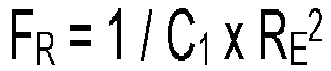
- On the other hand, the general functional equation of reaction flowmeters has the expression:

- Replacing the specific expression of FR in the general functional relation of reaction flowmeters, it results:


- By supplying the electrical resistance RE with a constant current of a very small value of approximately 1mA results an electrical voltage proportional to RE which is measured in the electronic block by an electrical voltage transducer.
- It follows that is linear the dependence between the output signal of
block 152, respectively the output signal of the flowmeter, which is proportional to RE, and to the measured flow Qm. - The effect of linearization is the increasing of the measurement interval of the reaction flowmeter, characterized by the ratio T = Qm, max / Qm, min to the value T2.
- According to the invention, an example of embodiment of the bypass type reaction flowmeter is shown in
Fig. 7 , consisting in the placement in bypass montage of two pipes, respectively themain pipe 153 and thesecondary pipe 154. On the main pipe is placed a fluidic resistance 155 (achieved by an orifice plate, nozzle, or short Venturi tube). Through the secondary pipe 154 (with small diameter) is taken the flow rate qm, of a small value, from the total flow rate Qm, with high value, the inlet flow rate in the main pipe 153 (with large diameter). - It is necessary to the hydraulic balance of the pressure drops on the two branches of the bypass (main pipe, respectively secondary pipe).
- By establishing, as previously presented, the relationship between flow rates qm and Qm, this configuration ensures the determination, by computing, and implicitly the measurement of the total flow rate Qm, by the effective measurement only of the secondary flow rate qm by the
reaction flowmeter 156, placed on thesecondary pipe 154. - The
reaction flowmeter 156 can be achieved in any of the construction variants indicated above. - According to the invention, further are presented the method and an example of a reaction flowmeter without moving parts and extended flow measurement, with the measurement of the output pushing force, by its electromagnetic balancing -
Fig.8 . - According to the claimed method, called the 'extended flow measurement method', the flowmeter, called the 'extended reaction flowmeter', ensures, through its configuration, the functional and implicitly constructive correlation between the two reaction flowmeters that make it up.
- In this sense, the extended flowmeter consists of a specific coupling of a "main flowmeter" with a "secondary flowmeter", having their flow ranges with correlated values, according to the provisions of this method.
- As shown in
Fig. 8 , the measured flow rate Q enters in the extended reaction flowmeter through itsinlet connection 157, consisting of theinlet connection 158 of the jet diverter 159, placed at the inlet of the flowmeter. - The jet divider 159, being actuated by its
solenoid 160, switches the flow of the incoming fluid, either at the outlet 161, to the "main flowmeter" (corresponding to position I of the diverter), or at theoutlet 162, to the "secondary flowmeter" (corresponding to position II of deviator) and vice versa, according to the order received from theelectronic block 163. - It is considered that the diverter 159 is initially controlled in Position I and, consequently, the introduced fluid is directed to flow only through the "main flow meter".
- The 'main flowmeter' consists of the
immobile inlet tube 164, thereaction tube 165 that generates the reaction force and theexhaust tube 166. - The
main reaction tube 165 is provided with theshaft 167, which is perpendicular to it and rigid with respect to it, ensuring the possibility of rotating thetube 165 with respect to the vertical axis of the shaft. - The reaction force FRM, generated by the
reaction tube 165, acts along the axis of this elbow at a distance LM to the axis of the shaft. - The
main reaction tube 165 is provided withboss 168. In this boss, at a distance Lo from the shaft axis, thepin 169 is rigidly incorporated. At the end of thepin 169 is rigidly fixed themagnet 170, which is implicitly positioned inside a small closed tube. 171. - The assembly formed by the pin169 and the
magnet 170 has the possibility to move relative to theclosed tube 171, which is configured as part of thehousing 172, of the extended reaction flowmeter. - Outside the
tube 171, is placed anannular magnet 173, which can move freely relative to it, its central hole having a corresponding diameter larger than the outer diameter of thetube 171. - The
magnet 173 is rigidly fixed to itssupport 174 which, in turn, is constructively fixed to the moving part of theforce sensor 175, permanently transmitting to it the pushing force Fo, received by magnetic coupling from themagnet 170. The value of the pushing force Fo,of output from the flowmeter, is proportional to the reaction force FRM. Theforce sensor 175 receives the output pushing force F0 (with the value F0 I corresponding to the position I of the jet diverter 159) and according to its principle of operation, at any very small tendency of displacement of its moving part (corresponding to a small variation of force F0 I), ensures electromagnetic balancing and its measurement at the same time. Consequently, the electrical output signal of theforce sensor 175 is proportional to the value of the pushing force F0 I and is applied to theelectronic block 163. - The
ring magnet 173, itssupport 174, theforce sensor 175 and theelectronic block 163 are properly positioned in the outer box of the extended reaction flowmeter, which has itsown housing 176, which is closed by the cover 177 with the screw-nut system 178, by tightening thegasket 179. - The
housing 176 is not in contact with the measured fluid being rigidly fixed to thehousing 172 of the flowmeter, which, on the contrary, is permanently in contact with the measured fluid. - The
force sensor 175 is rigidly fixed to thehousing 176, in a corresponding position relative to the system for receiving the pushing force, ensuring its rigorous measurement. -
Electronic block 163 calculates the value of the reaction force FRM, according to the known relationship between the forces F0 I and FRM, and then the corresponding value of the measured main flow rate QM, using the calibration curve QM = QM FRM), previously stored in its memory. - The QM flow rate is compensated with the pressure P and the temperature T, the parameters measured by
sensors - This is the first of the two functions of
block 163, because as previously presented, this block has two simultaneous functions, correlated with each other: the calculation of the instantaneous flow, respectively the control of the position of the diverter 159. - In this sense, the
electronic block 163 performs its second function of controlling and switching the position of the diverter 159, according to the algorithm of ensuring the operation of the extended reaction flowmeter, respecting the functional correlations presented in table 1 below:Table 1 The value of the measured flow Q Jet diverter status QSmin______QMmin Position II QSmax______QMmax Position I QMmin↑ (Only for the upward tendency of the flow rate) Switching from Position II to Position I QSmax ↓ (Only for the downward tendency of the flow rate) Switch from Position I to Position II - The complete continuity of the flow measurement along the entire measuring range of the extended reaction flowmeter is achieved by ensuring of a very small overlap zone ΔQ of the measuring ranges of the two component flowmeters of the extended reaction flowmeter ("main flowmeter" and "secondary flow meter"), as shown in the diagram below

- The overlapping zone ΔQ has a very small extension, respectively:

- Following this functional algorithm, the
electronic block 163 calculates, on the one hand, the instantaneous value of the measured flow rate Q and, on the other hand, according to this value commands the position of the diverter 159. Thus, is measured the entire flow range (QSmin ... QMmax), which is marked with a thickened line in the diagram, corresponding to the extended reaction flowmeter. - The overlapping zone ΔQ of the ranges of the two component flowmeters, practically completely covers the switching inertia zone of the diverter 159, achieving both the continuity of the flow measurement over the entire range of the flowmeter, including the overlapping zone ΔQ, nd a moderate value of measurement error for this zone, with a value of up to 50% of the maximum value of the Emax error, respectively:

- In this respect, the
block 163 will keep the diverter 159 in position I, only when the measured flow rate values by the "main flowmeter" fall within the range QMmax ... QSmax. - When the value of the measured flow by the "main flowmeter" decreases and tends to reach the value QM = QSmax, the
electronic block 163 commands the switching of the diverter 159 from its initial position I to position II, and now the introduced fluid is directed to flow only through the "secondary flowmeter", the flow measurement being continued only by this. - The 'secondary flowmeter' consists of the
immobile inlet tube 181, thereaction tube 182 and theexhaust tube 183. - The
fluid discharge tubes - The
secondary reaction tube 182 is provided with thevertical shaft 183, which ensures the potential rotation mobility of the tube relative to the shaft axis. - On the
secondary reaction tube 182 is placed theboss 184. Thepin 185 is rigidly incorporated in this boss, at a distance L1 from the shaft axis. - The relative positioning between the
main reaction tube 165 and thesecondary reaction tube 182 is performed constructively, so that thepin 185 is in permanent contact with themain reaction tube 165 and pushes it with the force Fs, for as long as the diverter 159 it is in position II, and the flow measurement is performed by the "secondary flowmeter". - In this way, under the effect of this force, the
pin 169 afferent to the main reaction tube will press with a force, having the amplified value F0 II, according to the provisions of those specified above. - The pushing force F0 II, is proportional to the force Fs and implicitly to the measured flow QS.
- Similar to the previous situation, in which the diverter 159 is in Position I, the pushing force F0 II, is measured by the
sensor 175, its value being proportional to that of the reaction force Fs, implicitly with the measured flow QS Functionally, as specified above, it is necessary to ensure the requirement F0max I = F0max II. - The output signal of the
sensor 175 is applied to block 163 which, on the one hand, calculates the value of the instantaneous flow rate Qs (compensated with P and T) and, on the other hand, controls the position of the diverter 159, according to the algorithm shown in table 1, respectively: - if: Qsmin ≤QS <QMmin the diverter is held in the same position II and the flow measurement is provided by the 'secondary flowmeter'
- if the Qs increases and tends to reach the value QS = QMmin, the diverter is switched from position II to position I and thus the flow measurement is continued by the 'main flowmeter'.
- It should be noted that because the overlap zone of the measurement ranges of the two flowmeters ("primary" and "secondary") is very small, of ΔQ = QSmax - QMmin = (0.01 ... 0.025) × QMmax, the switching of the diverter does not it practically bothers the flow measurement.
- Another example of embodiment the extended reaction flowmeter, is the one with the differential measurement of the pushing output force, presented in
Fig.9 . - The configuration of this type of flowmeters is largely similar to that of the extended reaction flowmeter with the measurement of the output pushing force, by its electromagnetic balancing.
- The essential difference, compared to the previous example, consists in the method of measuring the output pushing force and implicitly in the system of taking over of force.
- Also, it is mention that both the principle of the measurement method in question and the corresponding specific configuration of the system for taking this force, respectively the related functional equation, have already been indicated previously in the presentation "reaction flowmeter with reaction force measurement, by the differential measuring of the pressing pressure it produces".
- Consequently, only the specific aspects of the operation of the assembly of this type of extended reaction flowmeter are presented below.
- According to
Fig. 9 , the entered fluid through theconnection 186 of thediverter 187, according to the command of itssolenoid 188, is switched by the diverter, either to itsoutlet 189, to the "main flowmeter" (corresponding to position I of the diverter), or to itsoutlet 190 to "secondary flowmeter" (corresponding to the position II of the diverter) and vice versa, depending on the order received from theelectronic block 191. - It is considered that the
diverter 187 is initially controlled in position I and, consequently, the fluid is directed to flow only through the "main flowmeter". - According to the general functional algorithm, indicated in the example of the previous embodiment, the operation of this type of extended reaction flowmeter, respectively of the "main flowmeter" for this situation (corresponding to position I of the deviator 187) is similar to that of the type of flowmeter presented previously.
- A first essential difference consists in the way of taking the force F0 I from the
pin 192. - Now the pin presses on one side of the separating
diaphragm 193 with the force F0I, causing a pushing pressure po on its opposite face. - The pressure po, to which is permanently added the static pressure pf of the measured fluid, is taken over by the transmission liquid, which completely fills the connection 194, and their sum is applied to the high-pressure inlet of the Δp sensor, 195.
- The influence of the static pressure pf of the measured fluid is permanently canceled by its application, at the lowpressure inlet of the
Δp sensor 195, through theconnection 196. - Thus, the
sensor 195 ensures the differential measurement of the pushing pressure po, respectively its compensation with the temperature and pressure of the measured fluid, the sensor being provided with this additional function. - The output signal of the
sensor 195, which shows the value of the pushing pressure p, is applied to theelectronic block 191. - The
electronic block 191, starting from the calculation of the value of the pushing force Fo, corresponding to the reaction force FRM (which determined the occurrence of the pressure po) ensures the calculation of the instantaneous value of the measured flow QM, using the calibration curve QM = QM FRM), previously stored in his memory. - According to the operation algorithm of extended reaction flowmeters, DRE, presented in table 1, block 191 will keep the
diverter 187 in position I, only when the flow rate values QM, measured with the "main flowmeter", fall within the range (QMmax... QSmax). - When the value of the flow rate, measured by the "main flowmeter", decreases and tends to reach the value QM = Qsmax, the
electronic block 191 commands the switching of thediverter 187 from its initial position I to position II and now the entered fluid is directed to flow only through the "secondary flowmeter", the flow measurement being continued only by it. - As previously presented, the shaft of the
secondary reaction tube 197 is functionally positioned to the right of theshaft 198 of themain reaction tube 199, at a distance LA. - On the
secondary reaction tube 197, thepin 201 is fixed on theboss 200, at a distance L1 from the axis of the rotating shaft of thetube 197. - The relative positioning between the
main reaction tube 202 and thesecondary reaction tube 197 is performed constructively, so that thepin 201 to be in permanent contact with themain reaction tube 202 and to push it with force Fs for as long as thediverter 187 is in position II, and the flow measurement is provided by the secondary flowmeter. - In this way, under the effect of this force Fs, the
pin 201 of themain reaction tube 202 will press theseparation diaphragm 193 with a force having the amplified value F0 II, as shown previously. - The
Δ p sensor 195 and theelectronic block 191 are placed inside abox 203, tightly closed with thelid 204, not being in contact with the measuring fluid and being rigidly fixed on thehousing 199, which is in permanent contact with the measuring fluid. - Continuing, the taking over and the measuring of this pushing force F0 II, are performed identically by the Δp sensor, 195. Also the calculation by the
electronic block 191 of the measured flow rate value is performed identically as in the situation presented above, corresponding to the position I of thediverter 187. - According to the above, it is necessary to ensure the requirement F0max I = F0max II.
- Following the same functional algorithm, like that the type of extended reaction flowmeter shown above, depending of the value of the measured flow rate Qs, the
electronic block 191 controls the position of thediverter 187, as follows: - for QSmin ≤QS <QMmin, the diverter is held in position II, and the flow measurement is continued by the "secondary flowmeter"- if Qs increases and tends to reach the value QS = QMmin, the
diverter 187 switches from position II to position I and thus the flow measurement is continued by the 'main flowmeter'. - As a general remark, it should be mentioned that, since the overlap zone of the flow measurement ranges of the two flowmeters ("primary" and "secondary") is very small, respectively ΔQ = QSmax -QMmin-= (0.01... 0.025) × QMmax), the switching of the diverter practically do not bother the flow measurement.
- The advantages offered by the measurement method and the reaction flowmeter without moving parts, which are the object of this invention are:
- special flexibility, provided by the flow measurement method by measuring the reaction force, or its effects, to ensure the configuration of a wide diversity of types of reaction flowmeters without moving parts, destined for closed pipes, by solutions with: the nonlinearity of dependence between the output parameter and the flow rate, its linearization, respectively the coupling in by pass of such a flowmeter with a fluidic resistance, the extension of the flow measurement range, by coupling of such flowmeters, correlated to work successively depending on the measured flow rate value;
- direct measurement of mass flow rate;
- universality of use for the flow measuring both for liquids and gases or steam;
- simplicity of the configuration, and implicitly of the execution, of the fluid flow route through the flowmeter
- lack of wear between the parts in contact, without movement (fixed inlet tube - reaction tube)
- does not require an additive external energy consumption to ensure the operation of the reaction system for measuring the flow rate, consisting of the fixed inlet tube and the reaction tube;
- obtaining of some high values of the ratio Qm,max / Qm, min, optimally correlated with the interval of values of the maximum permissible errors of flow measurement
- robustness to the action of gas bubbles contained in multiphase fluids
- eventual solid particles in the measuring fluids do not affect the flow measurement
- ensures the permanent self-cleaning of the curved zones of the fluid flow path, by the functional use of some adequate values of the fluid flow velocity through the flowmeter
- reduced expenses regarding: the cost of flowmeters, their installation and related maintenance
Claims (11)
- Reaction flowmeter without moving parts, made up in individual configuration, of a primary element constituted by the association between a reference block (BR), realized in the form of a fixed horizontal access tube, and a sensitive block (BS) made as a curved quasi-immobile tube called immobile reaction element, and respectively a sensitive element (ES), in which the flow measurement is based either on the moment measurement of the force FR, or on the differential measurement of FR, characterized in that the flowmeter in the individual configuration is also based on the direct measurement of force FR, in two distinct functional solutions respectively, by electromagnetic balancing of FR, or with a load cell with a sensor type strain gauge, the flowmeter in individual configuration allowing and the linearization of the dependence relationship "the reaction force FR - measured flow", the flowmeter in configuration of bypass type, is obtained by placing a reaction flowmeter without moving parts on a secondary conduit, in parallel with a main pipe provided with a fluidic resistance, and the flowmeter in extended configuration is made in the form of a special functional connection with an intercorrelated operation, between two nonlinear reaction flowmeters, which have the two flow measurement ranges so correlated that, the values of one are a continuation of the other, with a very small overlap between them.
- Reaction flowmeter without moving parts according to claim 1, characterized in that in the individual configuration based on the measurement of the reaction force by electromagnetic balancing of the force, the measuring fluid enters in flowmeter through an inlet connection (102), ended with a nozzle (103) which enters in a nozzle (104) of a reaction tube (105), the fluid flowing through the reaction tube (105) and respectively a convergent outlet nozzle (106), then it is taken over by a nozzle (107) of a outlet connection (108), and the reaction tube is provided with a shaft (110), perpendicular on this and rigid with it, and the reaction tube (105) is provided with an outer boss (121) in which at a distance Lo of the shaft axis, a pin (122) is rigidly incorporated and rigidly fixed a magnet (123) placed inside a small closed tube (124) so that the subassembly formed by the pin (122) and the magnet (123) can move freely in relation to a closed tube (124) welded to a housing (109), and outside the tube (124), around it, is placed an annular magnet (125) with a free movement with respect to the tube (124), so that due to the magnetic coupling between the magnets (124) and (125), any variation of the force F0, followed by the moving tendency of the pin (121), respectively of the inner magnet (123), determines the moving tendency of the outer magnet (125), and the magnet (125) is rigidly fixed to a support (126) constructively fixed to the movable part of a force sensor (127) and to which it permanently transmits the pushing force, received by the magnet (125) respectively by the inner magnet (123), having the instantaneous value Fo and thus that the force sensor (127), which receives the pushing force Fo, at any very small moving tendency of its moving part, corresponding to any small variation of the force Fo, ensures its electromagnetic balancing, and at the same time the measuring of this force, and the electrical output signal of the sensor (127), proportional to the value of the measured force Fo, is applied to a electronic computing block (128) which calculates the corresponding value of the reaction force FR, according to the known analytical relation between the forces FR and Fo, and on this base, the block 128, having the calibration curve Qm = Qm (FR) previously stored, provides the calculation of the instantaneous value of the mass flow Qm compensated with T and P, these parameters being measured by sensors 133 and 134 corresponding to the measured value of Fo, respectively FR and generates an electrical output signal, proportional to the respective measured value of Qm.
- Reaction flowmeter without moving parts according to claim 1, characterized in that in the configuration with direct measurement of the reaction force, in the version with load cell with strain gauge type sensor, the structure and operation are similar to the configuration according to claim 2, but the item (127) is a load cell with strain gauge type sensor instead that with force measurement by its electromagnetic balancing.
- Reaction flowmeter without moving parts according to claim 1, characterized in that in the configuration with linear dependence between the output parameter and the measured flow, the measuring fluid enters in the flowmeter through an inlet connection (135), then passes through a reaction tube (136), with which it is articulated through a shaft (137) and then exits through an outlet connection (138), the mass flow Qm determines the generation of a reaction force FR, which tends to rotate the reaction tube (136) relatively to the shaft (137), and corresponding to the variation of the reaction force at the value FR, under its effect, the reaction tube (136) is rotated and the shaft (137), being rigid with the reaction tube (136), is equally rotated with the angle α, together with a magnet (140), stiffened with respect to the shaft (137), and a magnet (142) from inside of a housing (139) of the flowmeter determines, by magnetic coupling, the rotation with the same angle α of the external magnet (142), the angle α being the twisting angle of a helical spring (144), fixed with an end on its support (145), and with the other end of a rod of a circular sector (146), which in turn is rigidly fixed, by gluing, on the outer magnet (142), thus rotating in its turn with the angle α, and by mechanical coupling the crown of the circular sector (146) transmits its rotational movement to a roller (147), implicitly to a shaft (148), to which this is rigidly fixed, and a radial resistive arm (149), is rigidly fixed to the roller (147), arm which is a rod made of electrically insulating material on which is uniformly wound an electrical resistance made of a wire with very high resistivity, and a cam (150) rigidly placed on the housing cover (139) and has glued on its entire outer contour an electrical conductor (151), and thus due the radial resistive arm (149), is in permanent contact with the conductor (151), the contact point being the one corresponding to the length R of the cam radius corresponding to the value of the rotation angle β, implicitly the value of the electrical resistance RE (β) of the resistive arm (149), being detected as being that between its central point A and the point B of contact with the electrical conductor (151), corresponding to the radius R (β) corresponding to the angle β, and the electrical resistance RE (β) between points A and C is detected by an electronic block (152), which after processing according to the analytical relationship, already stored in its software, the block (152), emits the electrical output signal of the flowmeter.
- Reaction flowmeter without moving parts according to claim 1, characterized in that in the bypass type configuration, two conduits are placed in bypass mounting, respectively a main conduit (153) and a secondary conduit (154) so that on the main conduit is placed a fluid resistance (155) made by an orifice plate, nozzle, or short Venturi tube, and on the secondary conduit (154), with small diameter, it is placed a reaction flowmeter (156) through which it takes and measures the flow q, of a small value, from the total flow Q, of entry into the main conduit (153) with large diameter, the reaction flowmeter (156) can be made in any of the individual configurations previously claimed.
- Reaction flowmeter without moving parts according to claim 1, characterized in that in the configuration with the extended structure, with the measurement of the output pushing force by electromagnetic balancing, the measured flow rate Q enters through an input connection (157), consisting of the input connection (158) of a jet diverter (159), placed at the inlet of the flowmeter, the jet diverter (159), being actuated by a solenoid (160), switches the flow rate of the incoming fluid, either at an outlet (161), to the "main flowmeter" corresponding to position I of the diverter, or at an outlet (162), to the "secondary flowmeter", corresponding to position II of the diverter and vice versa, according to the command received from an electronic block (163) so that if the diverter (159) is initially controlled in Position I and, consequently, the fluid flows only through the "main flowmeter", which consists from a immobile inlet tube (164), a reaction tube (165) that generates the reaction force and an exhaust tube (166), the main tube (165) being provided with a shaft (167) perpendicular to it and rigid towards it, ensuring the possibility of rotating the tube (165) relatively to the vertical axis of the shaft, and the reaction force FRM, generated by the reaction tube (165), acts at a distance LM from the axis of the shaft, and the main reaction tube (165) is provided with a boss (168) in which at a distance Lo from the shaft axis, a pin (169) is rigidly embedded at the end of which is fixed rigidly a magnet (170) positioned inside a small closed tube (171), the assembly consisting of the pin (169) and the magnet (1700 being able to move free relatively to the closed tube (171), and outside the tube (171), is placed an annular magnet (173), which can move freely relative to it, rigidly fixed to its support (174) which, in its turn, is constructively fixed to the movable part of a force sensor (175), permanently transmitting to it the output pushing force Fo, received by coupling magnetic from the magnet (170) and proportional to the reaction force FRM and the force sensor (175) receives the output pushing force F0 with the value F0 I, corresponding to the position I of the jet deflector (159) ensuring electromagnetic balancing and its measurement, consequently, the electrical output signal of the force sensor (175) is proportional to the value of the pushing force F0 I and is applied to an electronic block (163) which calculates the value of the reaction force FRM, according to the known relationship between the forces F0 I and FRM, and then the corresponding value of the measured main flow rate QM, using the calibration curve QM = QM FRM), previously stored in its memory.
- Reaction flowmeter without moving parts according to claim 1, characterized in that in the configuration with the extended structure, with the differential measurement of the pushing force, the fluid entered through a connection (186), corresponding to a jet diverter (187), according to the command of a solenoid (188) thereof, is switched by the diverter, either to an its output (189), to the "main flowmeter" corresponding to position I of the diverter, or to another output of its (190) to the "secondary flowmeter" corresponding to position II of the diverter and vice versa, depending on the order received from an electronic block (191) thus if the diverter (187) is initially controlled in position I and the fluid is directed to flow only through the "main flowmeter", a pin (192) presses on one side of a separation diaphragm (193) with the force F0 I, causing a pushing pressure p0 on its opposite side. the pressure po, to which is permanently added the static pressure pf of the measured fluid, is taken over by the transmission fluid, which completely fills a connection (194), and their sum is applied to the high pressure inlet of a Δp sensor, (195), the influence of the static pressure pf of the measured fluid being permanently canceled by its application, to the low pressure inlet of the Δp sensor,(195) by a connection (196), so that the sensor (195) ensures the differential measurement of the pushing pressure p0, respectively its compensation with temperature and the pressure of the measured fluid, and the output signal of the sensor (195), which reproduces the value of the pushing pressure po, is applied to an electronic block (191) having as starting point the calculation of the value of the pushing force Fo, corresponding to the reaction force FRM which determined the pressure po ensures the calculation of the instantaneous value of the measured flow rate QM, using the calibration curve QM = QM (FRM), previously stored in its memory, constructively the relative positioning between a main reaction tube (202) and a secondary reaction tube (197) being thus performed that a pin (201) be in permanent contact with the main reaction tube (202) and pushes it with the force FS for the whole period while the diverter (187) is in position II, and the flow measurement is ensured by the secondary flowmeter, in this way, under the effect of this force Fs, the pin (201) of the main reaction tube (202) will press the separation diaphragm (193) with a force having the amplified value F0 II, the Δp sensor (195) and the electronic block (191) being placed inside a box (203), closed sealed with a cover (204), and the taking and measuring of this pushing force F0 II, are performed identically by the Δp sensor (195) including the calculation by the electronic block (191) of the value measured flowrate identical to the situation corresponding to position I of the diverter (187), the measurement principle imposing the need to ensure the requirement F0max I = F0max II, and depending on the value of the measured flow Qs, the electronic block (191) controls the position of the diverter (187).
- Flow measurement method in base on the reaction flowmeter without moving parts, according to claim 1, characterized in that it involves completing the following steps:Step 1- establishing for technical reasons related to the nature of the measured fluid, the value of the flow rate and availability, of the type of specific configuration used by flowmeter: individual, bypass or extended, mentioning that all of them unitarily use in their structures a flow measurement system composed by the free coupling, with a shaft, of two parts with distinct and correlated functional role, respectively a reference block BR immobile and a sensitive block BS potential mobile, both blocks having the same own specific configuration for all types of reaction flowmeters;Step 2. - introduction of the fluid with the measuring flow rate Qm = A xv xp in flowmeter through a reference block BR achieved as an extension of the inlet connection shaped as a immobile horizontal tube ended with a convergent nozzle which constructively ensures the functional constancy, with respect to flow rate variation, of the flow area value A = XR constituting the characteristic parameter XR of the flowmeter, determining the highlighting of the variable parameter Xv = v of the flowmeter, respectively the fluid velocity v, variable with the flow rate;Step 3 - taking over the fluid velocity v as the input parameter of the sensitive block BS of the flowmeter and obtaining at its output of a reaction force FR due to its specific shape of a quasi-immobile horizontal tube bent 2 at 900 provided with an inlet spherical convergent nozzle and an outlet convergent nozzle, being called reaction element, the fluid being discharged from the flowmeter by taking over, without contact, by its outlet connection, which is collinear with the inlet connection the fluid being discharged from the flowmeter by taking over, without contact, by its outlet connection, which is collinear with the inlet connectionStep 4 -taking over and measuring the characteristic parameter Xc of the flowmeter, on the basis of which the flow rate is computed, directly or by multiplication with a proportionality ratio, through solutions specific to the type of flowmeter configuration:A. in individual configuration with nonlinear dependence of the output parameter - measured flow rate- the moment of the reaction force, either- the differential pressure exerted by the reaction force, either- reaction force;B. in individual configuration with linear dependence of the output parameter-measured flow rate;- reaction force followed by the electric voltage generated at the output by using a non-linear transformation cam;C. in bypass configuration- the ratio between the secondary mass flow rate measured on a secondary conduit by the reaction flowmeter without moving parts and the main mass flow rate flowing through a main conduit restricted by a fluidic resistance;D. in extended configuration- the value of the switching flow rate of the flow measurement from one flowmeter to another, by means of a jet diverter, between the measurement ranges of the two component flowmeters, so correlated that one is practically a continuation of the other, in function of which intervenes an intermediate parameter of flow rate calculation specifically to the flowmeter in operation;Step 5 - taking over the intermediate parameter as the case may be, through a sensor of the moment of force,differential pressure sensor or respectively a force sensor;Step 6 - electronic processing of the parameters in order to render the effective value of the measured flow rate.
- Flow measurement method. based on the reaction flowmeter without moving parts, according to claim 8, characterized in that in order to execute the procedure from STEP 4 B, a reaction flowmeter without moving parts based on the measurement of the reaction force based on the nonlinear dependence relation between the reaction force FR and the measured flow Qm, a linearization solution is applied to it by means of a nonlinear transformation cam of the force FR in the output parameter Xi = FR 1/2, so that the dependence between the output parameter XI and the measured flow Qm is linearized according to the relation : Xi = (k1 × p-1) ×Qm.
- Flow measurement method. based on the reaction flowmeter without moving parts, according to claim 8, characterized in that in order to execute the procedure from STEP 4 C, a reaction flowmeter without moving parts is placed on a secondary conduit, in parallel with a main conduit provided with a fluidic resistance, the secondary conduit having a significantly smaller diameter than that of the main conduit so that by previous establishing of the relationship between the fluid flows through the two conduits, by the effective measurement
of a small secondary flow rate by the afferent reaction flowmeter, the configuration ensures the determination by calculation of the total measured flow rate. - Flow measurement method. based on the reaction flowmeter without moving parts, according to claim 8, characterized in that in order to execute the procedure from STEP 4 D, a configuration is achieved in the form of a special connection and special functional correlation, between two nonlinear reaction flowmeters, which have the two flow measurement ranges so correlated that the values of one are next to the other, with a very small overlap between them, and according to the stored algorithm, an electronic block of the flowmeter controls the switching, with a jet diverter, of the fluid flow through the main flowmeter, afferent to the branch with large diameter or through the secondary flowmeter afferent to the branch with small diameter, thus achieving an important extension of the total range of flow measurement.
Applications Claiming Priority (1)
| Application Number | Priority Date | Filing Date | Title |
|---|---|---|---|
| ROA202000774A RO135767A2 (en) | 2020-11-24 | 2020-11-24 | Reaction flow meter without mobile parts with individual by-pass and extended configuration and flow measuring method based thereon |
Publications (1)
| Publication Number | Publication Date |
|---|---|
| EP4001856A1 true EP4001856A1 (en) | 2022-05-25 |
Family
ID=78770312
Family Applications (1)
| Application Number | Title | Priority Date | Filing Date |
|---|---|---|---|
| EP21020546.4A Pending EP4001856A1 (en) | 2020-11-24 | 2021-11-04 | Reaction flow meter without moving parts in individual, by-pass and respectively extended configuration, and a method of measuring the flow based on it |
Country Status (2)
| Country | Link |
|---|---|
| EP (1) | EP4001856A1 (en) |
| RO (1) | RO135767A2 (en) |
Cited By (4)
| Publication number | Priority date | Publication date | Assignee | Title |
|---|---|---|---|---|
| CN117073781A (en) * | 2023-08-14 | 2023-11-17 | 江苏双碳环境技术有限公司 | Large-section pipeline carbon dioxide flow accurate measurement equipment based on balance method |
| DE102022126228A1 (en) * | 2022-10-10 | 2024-04-11 | Diehl Metering Gmbh | Fluid meters, especially water meters |
| EP4471385A1 (en) | 2023-05-29 | 2024-12-04 | Motit, Horia Mihai | Functional method of linearizing the dependence of the force exerted on the reaction element of a flowmeter with the flow rate, and linear reaction flowmeter configured on the basis of that method |
| EP4667879A1 (en) | 2024-06-17 | 2025-12-24 | Motit, Horia Mihai | Method of modulating the dependence on flow of the force exerted on the reaction element in the structure of a flowmeter and flowmeter with modulated reaction configured on the basis of the method |
Citations (13)
| Publication number | Priority date | Publication date | Assignee | Title |
|---|---|---|---|---|
| SE157135C1 (en) * | 1953-03-20 | 1956-12-04 | ||
| US2897672A (en) * | 1955-10-27 | 1959-08-04 | Gen Electric | Flow meter |
| US3203241A (en) * | 1962-01-04 | 1965-08-31 | Badger Meter Mfg Co | Flow measuring device |
| US3293913A (en) * | 1964-06-24 | 1966-12-27 | Nat Distillers Chem Corp | Jet reaction flowmeter |
| US3538769A (en) * | 1966-10-14 | 1970-11-10 | Kamekichi Shiba | Movable tube flowmeter of angular momentum type |
| US4612814A (en) * | 1982-01-06 | 1986-09-23 | Dowell Schlumberger Incorporated | Flow meter and densitometer apparatus |
| US4677859A (en) * | 1984-08-04 | 1987-07-07 | The British Petroleum Company, P.L.C. | Flow meter |
| US5121658A (en) * | 1988-06-20 | 1992-06-16 | Lew Hyok S | Mass-volume flowmeter |
| WO1997002470A1 (en) * | 1995-07-05 | 1997-01-23 | Industrial Research Limited | A total momentum flow meter |
| US5861561A (en) * | 1996-01-17 | 1999-01-19 | Micro Motion, Inc. | Bypass type coriolis effect flowmeter |
| US20030167836A1 (en) * | 2000-04-25 | 2003-09-11 | Mattar Wade M. | Low-flow extension for flow measurement device |
| EP3588016A2 (en) * | 2018-06-25 | 2020-01-01 | Horia Mihai Motit | A method of measuring the flow based on the action of a reaction force and a reaction flowmeter performed according to the method thereof |
| EP3364159B1 (en) | 2017-02-20 | 2020-01-22 | Motit Horia Mihai | Computer-implemented method for unitary synthesis and design of flow meters and of compound gauging structures |
-
2020
- 2020-11-24 RO ROA202000774A patent/RO135767A2/en unknown
-
2021
- 2021-11-04 EP EP21020546.4A patent/EP4001856A1/en active Pending
Patent Citations (14)
| Publication number | Priority date | Publication date | Assignee | Title |
|---|---|---|---|---|
| SE157135C1 (en) * | 1953-03-20 | 1956-12-04 | ||
| US2897672A (en) * | 1955-10-27 | 1959-08-04 | Gen Electric | Flow meter |
| US3203241A (en) * | 1962-01-04 | 1965-08-31 | Badger Meter Mfg Co | Flow measuring device |
| US3293913A (en) * | 1964-06-24 | 1966-12-27 | Nat Distillers Chem Corp | Jet reaction flowmeter |
| US3538769A (en) * | 1966-10-14 | 1970-11-10 | Kamekichi Shiba | Movable tube flowmeter of angular momentum type |
| US4612814A (en) * | 1982-01-06 | 1986-09-23 | Dowell Schlumberger Incorporated | Flow meter and densitometer apparatus |
| US4677859A (en) * | 1984-08-04 | 1987-07-07 | The British Petroleum Company, P.L.C. | Flow meter |
| US5121658A (en) * | 1988-06-20 | 1992-06-16 | Lew Hyok S | Mass-volume flowmeter |
| WO1997002470A1 (en) * | 1995-07-05 | 1997-01-23 | Industrial Research Limited | A total momentum flow meter |
| US5861561A (en) * | 1996-01-17 | 1999-01-19 | Micro Motion, Inc. | Bypass type coriolis effect flowmeter |
| US20030167836A1 (en) * | 2000-04-25 | 2003-09-11 | Mattar Wade M. | Low-flow extension for flow measurement device |
| EP3364159B1 (en) | 2017-02-20 | 2020-01-22 | Motit Horia Mihai | Computer-implemented method for unitary synthesis and design of flow meters and of compound gauging structures |
| EP3588016A2 (en) * | 2018-06-25 | 2020-01-01 | Horia Mihai Motit | A method of measuring the flow based on the action of a reaction force and a reaction flowmeter performed according to the method thereof |
| RO133994A2 (en) | 2018-06-25 | 2020-03-30 | Horia Mihai Motit | Method for measuring the flow rate, based on the action of a reaction force and reaction flowmeter manufactured based on said method |
Cited By (4)
| Publication number | Priority date | Publication date | Assignee | Title |
|---|---|---|---|---|
| DE102022126228A1 (en) * | 2022-10-10 | 2024-04-11 | Diehl Metering Gmbh | Fluid meters, especially water meters |
| EP4471385A1 (en) | 2023-05-29 | 2024-12-04 | Motit, Horia Mihai | Functional method of linearizing the dependence of the force exerted on the reaction element of a flowmeter with the flow rate, and linear reaction flowmeter configured on the basis of that method |
| CN117073781A (en) * | 2023-08-14 | 2023-11-17 | 江苏双碳环境技术有限公司 | Large-section pipeline carbon dioxide flow accurate measurement equipment based on balance method |
| EP4667879A1 (en) | 2024-06-17 | 2025-12-24 | Motit, Horia Mihai | Method of modulating the dependence on flow of the force exerted on the reaction element in the structure of a flowmeter and flowmeter with modulated reaction configured on the basis of the method |
Also Published As
| Publication number | Publication date |
|---|---|
| RO135767A2 (en) | 2022-05-30 |
Similar Documents
| Publication | Publication Date | Title |
|---|---|---|
| EP4001856A1 (en) | Reaction flow meter without moving parts in individual, by-pass and respectively extended configuration, and a method of measuring the flow based on it | |
| US7921726B2 (en) | Fluid sensor with mechanical positional feedback | |
| EP0593164B1 (en) | Variable area flowmeter | |
| CN100487387C (en) | Scalable averaging insertion vortex flow meter | |
| US7096738B2 (en) | In-line annular seal-based pressure device | |
| US7082840B2 (en) | Flanged vortex flowmeter with unitary tapered expanders | |
| US6298734B1 (en) | Rocker style sensor system for use in a vortex shedding flowmeter | |
| EP0171937B1 (en) | Flow meter | |
| KR102545821B1 (en) | Compact Ultrasonic Flowmeters and Compact Ultrasonic Flowmeters for Gas | |
| EP3588016A2 (en) | A method of measuring the flow based on the action of a reaction force and a reaction flowmeter performed according to the method thereof | |
| KR20040081491A (en) | Flow regulating valve, flow rate measuring device, flow control device, and flow rate measuring method | |
| US8844372B2 (en) | Vortex flow meter | |
| CN104215360B (en) | Calorimeter based on novel movable differential pressure type flowmeter | |
| EP4471385B1 (en) | Functional method of linearizing the dependence of the force exerted on the reaction element of a flowmeter with the flow rate, and linear reaction flowmeter configured on the basis of that method | |
| US4986135A (en) | Apparatus and method for measuring fluid flow and density | |
| CN213543699U (en) | High-precision analog control type flowmeter | |
| US20240295422A1 (en) | Sensor for detecting pressure fluctuations in a flowing fluid, and measurement system formed therewith | |
| US3495464A (en) | Device for measuring liquid density | |
| CN115790741B (en) | Intelligent flowmeter with wide adjustable measuring range | |
| CA1036388A (en) | Barometrically compensated pressure index continuous integrator for measuring throughput fluid flow of meters | |
| US4002067A (en) | Low friction absolute pressure continuous integrator | |
| JPH09196716A (en) | Simple flow rate measuring apparatus | |
| WO1997040350A1 (en) | Differential pressure device | |
| KR20220137349A (en) | Ultrasonic Flow Meter | |
| CN121433336A (en) | An intrinsically safe flow measurement and control device for mining |
Legal Events
| Date | Code | Title | Description |
|---|---|---|---|
| PUAI | Public reference made under article 153(3) epc to a published international application that has entered the european phase |
Free format text: ORIGINAL CODE: 0009012 |
|
| STAA | Information on the status of an ep patent application or granted ep patent |
Free format text: STATUS: THE APPLICATION HAS BEEN PUBLISHED |
|
| AK | Designated contracting states |
Kind code of ref document: A1 Designated state(s): AL AT BE BG CH CY CZ DE DK EE ES FI FR GB GR HR HU IE IS IT LI LT LU LV MC MK MT NL NO PL PT RO RS SE SI SK SM TR |
|
| STAA | Information on the status of an ep patent application or granted ep patent |
Free format text: STATUS: REQUEST FOR EXAMINATION WAS MADE |
|
| 17P | Request for examination filed |
Effective date: 20220905 |
|
| RBV | Designated contracting states (corrected) |
Designated state(s): AL AT BE BG CH CY CZ DE DK EE ES FI FR GB GR HR HU IE IS IT LI LT LU LV MC MK MT NL NO PL PT RO RS SE SI SK SM TR |
|
| STAA | Information on the status of an ep patent application or granted ep patent |
Free format text: STATUS: EXAMINATION IS IN PROGRESS |
|
| 17Q | First examination report despatched |
Effective date: 20230926 |