EP4471368A1 - Heat exchanger, and refrigeration cycle device - Google Patents
Heat exchanger, and refrigeration cycle device Download PDFInfo
- Publication number
- EP4471368A1 EP4471368A1 EP24733059.0A EP24733059A EP4471368A1 EP 4471368 A1 EP4471368 A1 EP 4471368A1 EP 24733059 A EP24733059 A EP 24733059A EP 4471368 A1 EP4471368 A1 EP 4471368A1
- Authority
- EP
- European Patent Office
- Prior art keywords
- space
- refrigerant
- sub
- heat exchanger
- opening
- Prior art date
- Legal status (The legal status is an assumption and is not a legal conclusion. Google has not performed a legal analysis and makes no representation as to the accuracy of the status listed.)
- Pending
Links
Images








Classifications
-
- F—MECHANICAL ENGINEERING; LIGHTING; HEATING; WEAPONS; BLASTING
- F28—HEAT EXCHANGE IN GENERAL
- F28F—DETAILS OF HEAT-EXCHANGE AND HEAT-TRANSFER APPARATUS, OF GENERAL APPLICATION
- F28F9/00—Casings; Header boxes; Auxiliary supports for elements; Auxiliary members within casings
- F28F9/02—Header boxes; End plates
- F28F9/026—Header boxes; End plates with static flow control means, e.g. with means for uniformly distributing heat exchange media into conduits
- F28F9/027—Header boxes; End plates with static flow control means, e.g. with means for uniformly distributing heat exchange media into conduits in the form of distribution pipes
- F28F9/0275—Header boxes; End plates with static flow control means, e.g. with means for uniformly distributing heat exchange media into conduits in the form of distribution pipes with multiple branch pipes
-
- F—MECHANICAL ENGINEERING; LIGHTING; HEATING; WEAPONS; BLASTING
- F25—REFRIGERATION OR COOLING; COMBINED HEATING AND REFRIGERATION SYSTEMS; HEAT PUMP SYSTEMS; MANUFACTURE OR STORAGE OF ICE; LIQUEFACTION SOLIDIFICATION OF GASES
- F25B—REFRIGERATION MACHINES, PLANTS OR SYSTEMS; COMBINED HEATING AND REFRIGERATION SYSTEMS; HEAT PUMP SYSTEMS
- F25B39/00—Evaporators; Condensers
-
- F—MECHANICAL ENGINEERING; LIGHTING; HEATING; WEAPONS; BLASTING
- F25—REFRIGERATION OR COOLING; COMBINED HEATING AND REFRIGERATION SYSTEMS; HEAT PUMP SYSTEMS; MANUFACTURE OR STORAGE OF ICE; LIQUEFACTION SOLIDIFICATION OF GASES
- F25B—REFRIGERATION MACHINES, PLANTS OR SYSTEMS; COMBINED HEATING AND REFRIGERATION SYSTEMS; HEAT PUMP SYSTEMS
- F25B39/00—Evaporators; Condensers
- F25B39/02—Evaporators
-
- F—MECHANICAL ENGINEERING; LIGHTING; HEATING; WEAPONS; BLASTING
- F25—REFRIGERATION OR COOLING; COMBINED HEATING AND REFRIGERATION SYSTEMS; HEAT PUMP SYSTEMS; MANUFACTURE OR STORAGE OF ICE; LIQUEFACTION SOLIDIFICATION OF GASES
- F25B—REFRIGERATION MACHINES, PLANTS OR SYSTEMS; COMBINED HEATING AND REFRIGERATION SYSTEMS; HEAT PUMP SYSTEMS
- F25B47/00—Arrangements for preventing or removing deposits or corrosion, not provided for in another subclass
- F25B47/02—Defrosting cycles
- F25B47/022—Defrosting cycles hot gas defrosting
- F25B47/025—Defrosting cycles hot gas defrosting by reversing the cycle
-
- F—MECHANICAL ENGINEERING; LIGHTING; HEATING; WEAPONS; BLASTING
- F25—REFRIGERATION OR COOLING; COMBINED HEATING AND REFRIGERATION SYSTEMS; HEAT PUMP SYSTEMS; MANUFACTURE OR STORAGE OF ICE; LIQUEFACTION SOLIDIFICATION OF GASES
- F25B—REFRIGERATION MACHINES, PLANTS OR SYSTEMS; COMBINED HEATING AND REFRIGERATION SYSTEMS; HEAT PUMP SYSTEMS
- F25B49/00—Arrangement or mounting of control or safety devices
- F25B49/02—Arrangement or mounting of control or safety devices for compression type machines, plants or systems
-
- F—MECHANICAL ENGINEERING; LIGHTING; HEATING; WEAPONS; BLASTING
- F28—HEAT EXCHANGE IN GENERAL
- F28F—DETAILS OF HEAT-EXCHANGE AND HEAT-TRANSFER APPARATUS, OF GENERAL APPLICATION
- F28F1/00—Tubular elements; Assemblies of tubular elements
- F28F1/02—Tubular elements of cross-section which is non-circular
- F28F1/04—Tubular elements of cross-section which is non-circular polygonal, e.g. rectangular
-
- F—MECHANICAL ENGINEERING; LIGHTING; HEATING; WEAPONS; BLASTING
- F28—HEAT EXCHANGE IN GENERAL
- F28F—DETAILS OF HEAT-EXCHANGE AND HEAT-TRANSFER APPARATUS, OF GENERAL APPLICATION
- F28F1/00—Tubular elements; Assemblies of tubular elements
- F28F1/10—Tubular elements and assemblies thereof with means for increasing heat-transfer area, e.g. with fins, with projections, with recesses
- F28F1/12—Tubular elements and assemblies thereof with means for increasing heat-transfer area, e.g. with fins, with projections, with recesses the means being only outside the tubular element
- F28F1/24—Tubular elements and assemblies thereof with means for increasing heat-transfer area, e.g. with fins, with projections, with recesses the means being only outside the tubular element and extending transversely
- F28F1/32—Tubular elements and assemblies thereof with means for increasing heat-transfer area, e.g. with fins, with projections, with recesses the means being only outside the tubular element and extending transversely the means having portions engaging further tubular elements
-
- F—MECHANICAL ENGINEERING; LIGHTING; HEATING; WEAPONS; BLASTING
- F28—HEAT EXCHANGE IN GENERAL
- F28F—DETAILS OF HEAT-EXCHANGE AND HEAT-TRANSFER APPARATUS, OF GENERAL APPLICATION
- F28F9/00—Casings; Header boxes; Auxiliary supports for elements; Auxiliary members within casings
- F28F9/02—Header boxes; End plates
- F28F9/026—Header boxes; End plates with static flow control means, e.g. with means for uniformly distributing heat exchange media into conduits
- F28F9/0278—Header boxes; End plates with static flow control means, e.g. with means for uniformly distributing heat exchange media into conduits in the form of stacked distribution plates or perforated plates arranged over end plates
-
- F—MECHANICAL ENGINEERING; LIGHTING; HEATING; WEAPONS; BLASTING
- F28—HEAT EXCHANGE IN GENERAL
- F28D—HEAT-EXCHANGE APPARATUS, NOT PROVIDED FOR IN ANOTHER SUBCLASS, IN WHICH THE HEAT-EXCHANGE MEDIA DO NOT COME INTO DIRECT CONTACT
- F28D1/00—Heat-exchange apparatus having stationary conduit assemblies for one heat-exchange medium only, the media being in contact with different sides of the conduit wall, in which the other heat-exchange medium is a large body of fluid, e.g. domestic or motor car radiators
- F28D1/02—Heat-exchange apparatus having stationary conduit assemblies for one heat-exchange medium only, the media being in contact with different sides of the conduit wall, in which the other heat-exchange medium is a large body of fluid, e.g. domestic or motor car radiators with heat-exchange conduits immersed in the body of fluid
- F28D1/04—Heat-exchange apparatus having stationary conduit assemblies for one heat-exchange medium only, the media being in contact with different sides of the conduit wall, in which the other heat-exchange medium is a large body of fluid, e.g. domestic or motor car radiators with heat-exchange conduits immersed in the body of fluid with tubular conduits
- F28D1/053—Heat-exchange apparatus having stationary conduit assemblies for one heat-exchange medium only, the media being in contact with different sides of the conduit wall, in which the other heat-exchange medium is a large body of fluid, e.g. domestic or motor car radiators with heat-exchange conduits immersed in the body of fluid with tubular conduits the conduits being straight
- F28D1/0535—Heat-exchange apparatus having stationary conduit assemblies for one heat-exchange medium only, the media being in contact with different sides of the conduit wall, in which the other heat-exchange medium is a large body of fluid, e.g. domestic or motor car radiators with heat-exchange conduits immersed in the body of fluid with tubular conduits the conduits being straight the conduits having a non-circular cross-section
- F28D1/05366—Assemblies of conduits connected to common headers, e.g. core type radiators
-
- F—MECHANICAL ENGINEERING; LIGHTING; HEATING; WEAPONS; BLASTING
- F28—HEAT EXCHANGE IN GENERAL
- F28D—HEAT-EXCHANGE APPARATUS, NOT PROVIDED FOR IN ANOTHER SUBCLASS, IN WHICH THE HEAT-EXCHANGE MEDIA DO NOT COME INTO DIRECT CONTACT
- F28D1/00—Heat-exchange apparatus having stationary conduit assemblies for one heat-exchange medium only, the media being in contact with different sides of the conduit wall, in which the other heat-exchange medium is a large body of fluid, e.g. domestic or motor car radiators
- F28D1/02—Heat-exchange apparatus having stationary conduit assemblies for one heat-exchange medium only, the media being in contact with different sides of the conduit wall, in which the other heat-exchange medium is a large body of fluid, e.g. domestic or motor car radiators with heat-exchange conduits immersed in the body of fluid
- F28D1/04—Heat-exchange apparatus having stationary conduit assemblies for one heat-exchange medium only, the media being in contact with different sides of the conduit wall, in which the other heat-exchange medium is a large body of fluid, e.g. domestic or motor car radiators with heat-exchange conduits immersed in the body of fluid with tubular conduits
- F28D1/053—Heat-exchange apparatus having stationary conduit assemblies for one heat-exchange medium only, the media being in contact with different sides of the conduit wall, in which the other heat-exchange medium is a large body of fluid, e.g. domestic or motor car radiators with heat-exchange conduits immersed in the body of fluid with tubular conduits the conduits being straight
- F28D1/0535—Heat-exchange apparatus having stationary conduit assemblies for one heat-exchange medium only, the media being in contact with different sides of the conduit wall, in which the other heat-exchange medium is a large body of fluid, e.g. domestic or motor car radiators with heat-exchange conduits immersed in the body of fluid with tubular conduits the conduits being straight the conduits having a non-circular cross-section
- F28D1/05366—Assemblies of conduits connected to common headers, e.g. core type radiators
- F28D1/05391—Assemblies of conduits connected to common headers, e.g. core type radiators with multiple rows of conduits or with multi-channel conduits combined with a particular flow pattern, e.g. multi-row multi-stage radiators
-
- F—MECHANICAL ENGINEERING; LIGHTING; HEATING; WEAPONS; BLASTING
- F28—HEAT EXCHANGE IN GENERAL
- F28F—DETAILS OF HEAT-EXCHANGE AND HEAT-TRANSFER APPARATUS, OF GENERAL APPLICATION
- F28F2215/00—Fins
- F28F2215/12—Fins with U-shaped slots for laterally inserting conduits
Definitions
- the present disclosure relates to a heat exchanger and a refrigeration cycle apparatus.
- the discloser of this application has found that, in a case where the dryness of the refrigerant flowing into the second space increases when the heat exchanger having the structure in PTL 1 ( Japanese Unexamined Patent Application Publication No. 2021-12018 ) is used, a difference may occur in the amounts of liquid refrigerant and gas refrigerant flowing through each flat tube, and the efficiency may decrease. From such a viewpoint, the discloser of this application has found that there is room for further improvement in the efficiency of the heat exchanger.
- a heat exchanger includes a plurality of flat tubes and a header.
- the header includes a first member, a second member, and a first plate.
- the first member forms a plurality of first spaces into which the flat tubes are inserted.
- the second member forms a second space into which a refrigerant flows.
- the first plate is provided between the first space and the second space.
- the first plate is provided with an opening. The opening allows the first space and the second space to communicate with each other.
- the refrigerant flows from the second space into the first space through the opening.
- the opening When viewed along the insertion direction of the flat tube with respect to the first space, the opening is arranged, at least partially, close to one end portion of the second space in a width direction of the flat tube.
- the opening formed in the first plate is arranged close to the end portion of the second space, the liquid refrigerant, which is likely to flow in the vicinity of the end portion of the second space in the width direction of the flat tube, may be easily distributed to the plurality of first spaces without unevenness.
- a heat exchanger according to a second aspect is the heat exchanger according to the first aspect, wherein when viewed along the insertion direction of the flat tube with respect to the first space, the opening is arranged, at least partially, close to both end portions of the second space in the width direction of the flat tube.
- the opening formed in the first plate is arranged close to both the end portions of the second space, and thus the liquid refrigerant, which is likely to flow in the vicinity of the end portions of the second space in the width direction of the flat tube, may be easily distributed to the plurality of first spaces without unevenness.
- a heat exchanger according to a third aspect is the heat exchanger according to the first aspect or the second aspect, wherein a width of the second space is a first width.
- the opening is arranged, at least partially, between an end portion of the second space and a position by 15% of the first width inside the second space from the end portion.
- the liquid refrigerant which is likely to flow in the vicinity of the end portion of the second space in the width direction of the flat tube, may be easily distributed to the plurality of first spaces without unevenness.
- a heat exchanger according to a fourth aspect is the heat exchanger according to any one of the first aspect to the third aspect, wherein, when viewed along the insertion direction of the flat tube with respect to the first space, the opening partially overlaps with one end portion of the second space in the width direction of the flat tube.
- the opening formed in the first plate is arranged to overlap with the end portion of the second space, and thus the liquid refrigerant, which is likely to flow in the vicinity of the end portion of the second space in the width direction of the flat tube, may be easily distributed to the plurality of first spaces without unevenness.
- a heat exchanger according to a fifth aspect is the heat exchanger according to the fourth aspect, wherein when viewed along the insertion direction, the opening partially overlaps with both the end portions of the second space in the width direction.
- the opening formed in the first plate is arranged to overlap with both the end portions of the second space, and thus the liquid refrigerant, which is likely to flow in the vicinity of the end portions of the second space in the width direction of the flat tube, may be easily distributed to the plurality of first spaces without unevenness.
- a heat exchanger according to a sixth aspect is the heat exchanger according to the fifth aspect, wherein when viewed along the insertion direction, the opening overlaps with the entire second space in the width direction.
- the liquid refrigerant flowing through the end portion of the second space in the width direction of the flat tube may be easily distributed to the plurality of first spaces without unevenness.
- a heat exchanger according to a seventh aspect is the heat exchanger according to any one of the first aspect to the sixth aspect, wherein when viewed along the insertion direction, the second member forms a main space and a sub-space.
- the main space includes a refrigerant inlet and a refrigerant outlet.
- the refrigerant moves from the refrigerant inlet to the refrigerant outlet in the main space.
- the sub-space guides the refrigerant having reached the refrigerant outlet of the main space to a vicinity of the refrigerant inlet of the main space.
- the opening communicates with the main space as the second space.
- the refrigerant since the loop structure having the main space and the sub-space is employed for dividing the flow of the refrigerant, the refrigerant may be easily distributed to the plurality of first spaces without unevenness especially.
- a heat exchanger according to an eighth aspect is the heat exchanger according to any one of the first aspect to the seventh aspect, wherein in the width direction, the width of the first space is larger than the width of the second space.
- the liquid refrigerant flowing through the end portion of the second space may be easily divided to the first spaces via the opening of the first plate without unevenness.
- a heat exchanger according to a ninth aspect is the heat exchanger according to any one of the first aspect to the eighth aspect, wherein the width of the opening in the thickness direction of the flat tube is equal to or more than 1 mm.
- the width of the opening in the thickness direction of the flat tube is equal to or more than 1 mm, it is possible to suppress the occurrence of an issue in which it is difficult for the liquid refrigerant to flow through the opening.
- a heat exchanger according to a tenth aspect is the heat exchanger according to any one of the first aspect to the ninth aspect, wherein one of the flat tube is inserted into each of the first spaces. One or more of the openings are provided for each of the first spaces.
- one of the flat tube is inserted corresponding to each of the first spaces, and the refrigerant from the second space is guided to each of the first spaces via the opening, and therefore, unevenness in the amount of refrigerant flowing into each of the flat tubes may be easily suppressed, as compared with a case where the plurality of flat tubes is inserted into each of the first spaces and the refrigerant having flowed into each of the first spaces is distributed to the plurality of flat tubes.
- a heat exchanger is the heat exchanger according to any one of the first aspect to the tenth aspect, wherein the plurality of flat tubes includes at least a first flat tube and a plurality of second flat tubes.
- the refrigerant having flowed through the first flat tube passes through a first portion of the header, into which the plurality of second flat tubes is inserted, and flows into the plurality of second flat tubes.
- the opening is arranged, at least partially, close to one end portion of the second space in the width direction.
- the dryness of the refrigerant becomes high when the refrigerant turns back at the header and flows into the plurality of second flat tubes.
- a difference may occur in the amounts of the liquid refrigerant and the gas refrigerant flowing through each of the second flat tubes, and the efficiency of heat exchange may decrease.
- a refrigeration cycle apparatus includes: the heat exchanger according to any one of the first aspect to the eleventh aspect configured to function as an evaporator; a compressor configured to compresses the refrigerant; a radiator configured to cool the refrigerant discharged from the compressor; and an expansion device configured to expands the refrigerant flowing out of the radiator to the heat exchanger.
- the air conditioning apparatus 1 is an apparatus capable of cooling and heating a space to be air-conditioned by performing a vapor compression refrigeration cycle.
- the type of the refrigeration cycle apparatus according to the present disclosure is not limited to the air conditioning apparatus and may be, for example, a hot water supply apparatus, a floor heater, or the like.
- the air conditioning apparatus 1 mainly includes a heat source unit 2, utilization units 3a, 3b, a liquid-refrigerant connection pipe 4, a gas-refrigerant connection pipe 5, and a control unit 50.
- the control unit 50 controls operations of constituent devices of the heat source unit 2 and the utilization units 3a, 3b.
- the liquid-refrigerant connection pipe 4 and the gas-refrigerant connection pipe 5 connect the heat source unit 2 and the utilization units 3a, 3b.
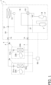
- the heat source unit 2 and the utilization units 3a, 3b are connected via the refrigerant connection pipes 4, 5, thereby configuring a refrigerant circuit 6 (see Fig. 1 ).
- a compressor 8 In the refrigerant circuit 6, a compressor 8, a flow direction switching mechanism 10, a first heat exchanger 11, a first expansion mechanism 12, a first closing valve 13, a second closing valve 14, second expansion mechanisms 31a, 31b, and second heat exchangers 32a, 32a, which will be described below, are connected by refrigerant pipes as illustrated in Fig. 1 .
- the first heat exchanger 11 is an example of a heat exchanger according to the present disclosure.
- the air conditioning apparatus 1 includes the one heat source unit 2 and the two utilization units 3a, 3b, but the number of units is merely an example.
- the air conditioning apparatus 1 may include a plurality of heat source units or may include one utilization unit or three or more utilization units. Further, the air conditioning apparatus 1 may be an integrated air conditioning apparatus in which a heat source unit and a utilization unit are integrally formed.
- refrigerant circuit 6 a refrigerant having a small global warming potential such as R290 or CO 2 is enclosed.
- the type of refrigerant is not limited to R290, CO 2 , or the like, and may be R32, R410A, R1234yf, R1234ze(E), or the like.
- the heat source unit 2 the utilization units 3a, 3b, the liquid-refrigerant connection pipe 4, the gas-refrigerant connection pipe 5, and the control unit 50 of the air conditioning apparatus 1 will be described below.
- the heat source unit 2 is, but is not limited thereto, is installed outdoors, for example, on the roof of the building or around the outer wall of the building where the air conditioning apparatus 1 is installed.
- the heat source unit 2 is a top-blowing type unit that takes in air from the side of a housing (not illustrated) that houses various devices of the heat source unit 2, and blows out the air that has exchanged heat with the refrigerant from above the housing.
- the type of the heat source unit 2 is not limited to the top-blowing type, and may be a side-blowing type in which the air having exchanged heat with the refrigerant is blown out from the side of the housing.
- the heat source unit 2 mainly includes an accumulator 7, the compressor 8, the flow direction switching mechanism 10, the first heat exchanger 11, the first expansion mechanism 12, the first closing valve 13, the second closing valve 14, and a first fan 15 (see Fig. 1 ).
- the heat source unit 2 includes a suction pipe 17, a discharge pipe 18, a first gas refrigerant pipe 19, a liquid refrigerant pipe 20, and a second gas refrigerant pipe 21 (see Fig. 1 ).
- the suction pipe 17 connects the flow direction switching mechanism 10 and the suction side of the compressor 8.
- the suction pipe 17 is provided with the accumulator 7.
- the discharge pipe 18 connects the discharge side of the compressor 8 and the flow direction switching mechanism 10.
- the first gas refrigerant pipe 19 connects the flow direction switching mechanism 10 and the gas end of the first heat exchanger 11.
- the liquid refrigerant pipe 20 connects the liquid end of the first heat exchanger 11 and the first closing valve 13.
- the first expansion mechanism 12 is provided in the liquid refrigerant pipe 20.
- the second gas refrigerant pipe 21 connects the flow direction switching mechanism 10 and the second closing valve 14.
- the compressor 8 is a device that suctions the low-pressure refrigerant in the refrigeration cycle that flows in from the suction pipe 17, compresses the refrigerant to raise the pressure to a high pressure in the refrigeration cycle, and discharges the refrigerant to the discharge pipe 18.
- the compressor 8 is, for example, a positive displacement compressor, but may be another type (a centrifugal compressor).
- the flow direction switching mechanism 10 is a mechanism that switches the flow direction of the refrigerant in the refrigerant circuit 6. According to the present embodiment, the flow direction switching mechanism 10 is a four-way switching valve.
- the flow direction switching mechanism 10 communicates the suction pipe 17 with the second gas refrigerant pipe 21 and communicates the discharge pipe 18 with the first gas refrigerant pipe 19 (such a connection state of the pipes by the flow direction switching mechanism 10 is referred to as a first state), thereby switching the flow direction of the refrigerant in the refrigerant circuit 6 (see the solid lines in Fig. 1 ) so that the refrigerant discharged by the compressor 8 is sent to the first heat exchanger 11.
- the flow direction switching mechanism 10 communicates the suction pipe 17 with the first gas refrigerant pipe 19 and communicates the discharge pipe 18 with the second gas refrigerant pipe 21 (such a connection state of the pipes by the flow direction switching mechanism 10 is referred to as a second state), thereby switching the flow direction of the refrigerant in the refrigerant circuit 6 (see the broken line in Fig. 1 ) so that the refrigerant discharged by the compressor 8 is sent to the second heat exchangers 32a, 32b.
- the flow direction switching mechanism 10 is not limited to a four-way switching valve and may be configured so as to be able to switch the flow direction of the refrigerant as described above by combining a plurality of electromagnetic valves and refrigerant pipes.
- the first heat exchanger 11 functions as a radiator (condenser) during the cooling operation or defrosting operation and functions as an evaporator (heat absorber) during the heating operation.
- the first heat exchanger 11 is an example of a heat exchanger in the claims.
- the structure of the first heat exchanger 11 and the flow of the refrigerant in the first heat exchanger 11 will be described below.
- the first expansion mechanism 12 is a mechanism that expands the refrigerant flowing between the first heat exchanger 11 and the second heat exchangers 32a, 32b of the utilization units 3a, 3b in the refrigerant circuit 6.
- the first expansion mechanism 12 is, for example, an electronic expansion valve whose opening degree is adjustable. The opening degree of the first expansion mechanism 12 is adjusted by the control unit 50 in accordance with the operating condition.
- the first fan 15 generates an airflow and supplies air to the first heat exchanger 11.
- the first fan 15 generates a flow of air that flows into the heat source unit 2 from the outside of the housing, passes through the first heat exchanger 11, and flows out of the housing.
- the first fan 15 is, for example, a propeller fan.
- the type of the first fan 15 is not limited to a propeller fan, and may be another type of fan.
- the utilization units 3a, 3b are installed in the space to be air-conditioned or in the vicinity of the space to be air-conditioned (for example, in the attic space of the space to be air-conditioned).
- the utilization unit 3a mainly includes a second expansion mechanism 31a, a second heat exchanger 32a, and a second fan 33a (see Fig. 1 ).
- the utilization unit 3b mainly includes a second expansion mechanism 31b, a second heat exchanger 32b, and a second fan 33b (see Fig. 1 ).
- the second expansion mechanisms 31a, 31b are mechanisms that expand the refrigerant flowing between the first heat exchanger 11 and the second heat exchangers 32a, 32b of the utilization units 3a, 3b in the refrigerant circuit 6.
- the second expansion mechanisms 31a, 31b are, for example, an electronic expansion valve whose opening degree is adjustable. The opening degree of the second expansion mechanisms 31a, 31b is adjusted by the control unit 50 in accordance with the operating condition.
- the second heat exchangers 32a, 32b function as a heat absorber (evaporator) to cool the indoor air during the cooling operation and function as a radiator (condenser) of the refrigerant to heat the indoor air during the heating operation.
- the liquid side of the second heat exchangers 32a, 32b is connected to the liquid-refrigerant connection pipe 4 via a refrigerant pipe, and the gas side of the second heat exchangers 32a, 32b is connected to the gas-refrigerant connection pipe 5 via a refrigerant pipe.
- the second heat exchangers 32a, 32b are, for example, cross-fin type fin-and-tube heat exchangers including a plurality of heat transfer tubes (not illustrated) and a plurality of fins (not illustrated).
- the second heat exchangers 32a, 32b exchange heat between the refrigerant and air
- the second heat exchanger of the utilization unit may be a heat exchanger that exchanges heat between the refrigerant and water.
- the second fans 33a, 33b generate a flow of air that flows into the utilization units 3a, 3b from the outside (air-conditioning target space) of a housing (not illustrated) that houses various devices of the utilization units 3a, 3b therein, passes through the second heat exchangers 32a, 32b, and flows out of the housing (air-conditioning target space).
- the second fans 33a, 33b are, for example, centrifugal fans.
- the refrigerant connection pipes 4, 5 are refrigerant pipes constructed on site when the air conditioning apparatus 1 is installed. One end of the liquid-refrigerant connection pipe 4 is connected to the first closing valve 13 of the heat source unit 2, and the other end of the liquid-refrigerant connection pipe 4 is connected to the refrigerant pipe connected to the liquid side of the second heat exchangers 32a, 32b of the utilization units 3a, 3b (see Fig. 1 ).
- gas-refrigerant connection pipe 5 One end of the gas-refrigerant connection pipe 5 is connected to the second closing valve 14 of the heat source unit 2, and the other end of the gas-refrigerant connection pipe 5 is connected to the refrigerant pipe connected to the gas side of the second heat exchangers 32a, 32b of the utilization units 3a, 3b (see Fig. 1 ).
- the control unit 50 is configured by communicably connecting control boards (not illustrated) including a CPU, a ROM, a RAM, and the like, which are provided in the heat source unit 2 and the utilization units 3a, 3b.
- control boards not illustrated
- a CPU central processing unit
- ROM read-only memory
- RAM random access memory
- the control unit 50 is illustrated at a position away from the heat source unit 2 and the utilization units 3a, 3b.
- control unit 50 is electrically connected to constituent devices of the air conditioning apparatus 1.
- the control unit 50 is electrically connected to, for example, the compressor 8, the flow direction switching mechanism 10, the first expansion mechanism 12, the first fan 15, the second expansion mechanisms 31a, 31b and the second fans 33a, 33b.
- the control unit 50 is also electrically connected to various sensors (not illustrated) provided in the heat source unit 2 and the utilization units 3a, 3b.
- the control unit 50 executes a program for controlling the air conditioning apparatus 1 (the CPU executes a program stored in the ROM) to control constituent devices of the air conditioning apparatus 1 based on an operation from a remote controller (not illustrated), measurement values of various sensors (not illustrated), and the like.
- the control unit 50 controls the constituent devices of the air conditioning apparatus 1 to cause the air conditioning apparatus 1 to execute a cooling operation or a heating operation. Further, when a predetermined condition is satisfied during the heating operation of the air conditioning apparatus 1, the control unit 50 switches the operation of the air conditioning apparatus 1 to the defrosting operation. The operation of the air conditioning apparatus 1 during each operation will be described below.
- the cooling operation, the heating operation, and the defrosting operation of the air conditioning apparatus 1 will be described.
- the defrosting operation is an operation for melting frost or ice sticked to the first heat exchanger 11, which is performed by temporarily interrupting the heating operation during the heating operation.
- the refrigerant circulates in the refrigerant circuit 6 through the compressor 8, the first heat exchanger 11, the first expansion mechanism 12, the second expansion mechanisms 31a, 31b, the second heat exchangers 32a, 32b, and the accumulator 7 in this order.
- the refrigerant circulates in the refrigerant circuit 6 through the compressor 8, the second heat exchangers 32a, 32b, the second expansion mechanisms 31a, 31b, the first expansion mechanism 12, the first heat exchanger 11, and the accumulator 7 in this order.
- the connection state of the pipes by the flow direction switching mechanism 10 is switched to the first state described above.
- the gas refrigerant at a low pressure (hereinafter simply referred to as a low pressure) in the refrigeration cycle suctioned into the compressor 8 from the suction pipe 17 is compressed by the compressor 8 to a high pressure (hereinafter simply referred to as a high pressure) in the refrigeration cycle, and is then discharged to the discharge pipe 18.
- the high-pressure gas refrigerant discharged to the discharge pipe 18 is sent to the first heat exchanger 11 through the flow direction switching mechanism 10.
- the high-pressure gas refrigerant sent to the first heat exchanger 11 radiates heat by exchanging heat with the air supplied by the first fan 15 in the first heat exchanger 11 functioning as a radiator of the refrigerant, and becomes a high-pressure liquid refrigerant.
- the high-pressure liquid refrigerant having radiated heat in the first heat exchanger 11 is sent to the second expansion mechanisms 3 1a, 3 1b through the first expansion mechanism 12, the first closing valve 13, and the liquid-refrigerant connection pipe 4.
- the refrigerant sent to the second expansion mechanisms 31a, 31b is decompressed to a low pressure by the second expansion mechanisms 31a, 31b, and becomes a low-pressure refrigerant in a gas-liquid two-phase state.
- the low-pressure refrigerant in a gas-liquid two-phase state decompressed by the second expansion mechanisms 31a, 31b is sent to the second heat exchangers 32a, 32b.
- the low-pressure refrigerant in a gas-liquid two-phase state sent to the second heat exchangers 32a, 32b exchanges heat with the air supplied by the second fans 33a, 33b and evaporated in the second heat exchanger 32a, 32b.
- the air cooled in the second heat exchangers 32a, 32b is blown out to the space to be air-conditioned.
- the low-pressure gas refrigerant evaporated in the second heat exchangers 32a, 32b passes through the gas-refrigerant connection pipe 5, the second closing valve 14, the flow direction switching mechanism 10, and the accumulator 7, and is again suctioned into the compressor 8.
- control unit 50 performs, for example, the following control.
- the mode of control by the control unit 50 described here is an example, and the control is not limited thereto.
- the control unit 50 controls the opening degree of the electronic expansion valve as an example of each of the second expansion mechanisms 31a, 31b so that the degree of superheating of the refrigerant at the outlet of each of the second heat exchangers 32a, 32b becomes a target degree of superheating based on a measurement value of a sensor (not illustrated). Further, the control unit 50 controls the operating capacity of the compressor 8 so that the evaporation temperature approaches the target evaporation temperature.
- connection state of the pipes by the flow direction switching mechanism 10 is switched to the above-described second state.
- the low-pressure gas refrigerant suctioned into the compressor 8 from the suction pipe 17 is compressed to a high pressure by the compressor 8, and then discharged to the discharge pipe 18.
- the high-pressure gas refrigerant discharged to the discharge pipe 18 is sent to the second heat exchangers 32a, 32b through the flow direction switching mechanism 10, the second closing valve 14, and the gas-refrigerant connection pipe 5.
- the high-pressure gas refrigerant sent to the second heat exchangers 32a, 32b exchanges heat with the air supplied by the second fans 33a, 33b in the second heat exchanger 32a, 32b to radiate heat, and becomes a high-pressure liquid refrigerant or a refrigerant in a gas-liquid two-phase state.
- the air heated by heat-exchanging with the refrigerant in the second heat exchangers 32a, 32b is blown out to the space to be air-conditioned.
- the high-pressure refrigerant that has radiated heat in the second heat exchangers 32a, 32b is sent to the first expansion mechanism 12 through the second expansion mechanisms 31a, 31b, the liquid-refrigerant connection pipe 4, and the first closing valve 13.
- the refrigerant sent to the first expansion mechanism 12 is decompressed by the first expansion mechanism 12 and becomes a low-pressure refrigerant in a gas-liquid two-phase state.
- the low-pressure refrigerant in a gas-liquid two-phase state decompressed by the first expansion mechanism 12 is sent to the first heat exchanger 11.
- the low-pressure refrigerant in a gas-liquid two-phase state sent to the first heat exchanger 11 is evaporated by heat exchange with the air supplied by the first fan 15 in the first heat exchanger 11 functioning as an evaporator of the refrigerant, and becomes a low-pressure gas refrigerant.
- the low-pressure refrigerant evaporated in the first heat exchanger 11 passes through the flow direction switching mechanism 10 and the accumulator 7 and is suctioned into the compressor 8 again.
- control unit 50 performs, for example, the following control.
- the mode of control by the control unit 50 described here is an example, and the control is not limited thereto.
- the control unit 50 controls the opening degree of the electronic expansion valve as an example of the first expansion mechanism 12 so that the degree of superheating of the refrigerant at the outlet of the first heat exchanger 11 becomes a target degree of superheating based on a measurement value of a sensor (not illustrated). Further, the control unit 50 controls the operating capacity of the compressor 8 so that the evaporation temperature approaches the target evaporation temperature. Further, the control unit 50 controls the opening degree and the like of an electronic expansion valve as an example of the first expansion mechanism 12 so that the dryness of the refrigerant at the inlet of the first heat exchanger 11 becomes a predetermined value.
- the control unit 50 When the start condition of the defrosting operation is satisfied during the heating operation, the control unit 50 temporarily switches the operation of the air conditioning apparatus 1 from the heating operation to the defrosting operation to defrost the first heat exchanger 11, and causes the first heat exchanger 11 to function as a radiator. Further, when a termination condition of the defrosting operation is satisfied, the control unit 50 terminates the defrosting operation and returns the operation of the air conditioning apparatus 1 to the heating operation. The description for the control contents of the control unit 50 during the defrosting operation will be omitted.
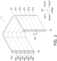
- Fig. 2 is a schematic perspective view of the first heat exchanger 11.
- Fig. 3 is a partially enlarged view of a heat exchange unit 27, which will be described below, of the first heat exchanger 11.
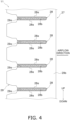
- Fig. 4 is a schematic view illustrating a state in which fins 29, which will be described below, are attached to flat tubes 28 in the heat exchange unit 27.
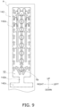
- Fig. 5 is a schematic configuration diagram of the first heat exchanger 11. Fig. 5 also illustrates how the refrigerant flows when the first heat exchanger 11 functions as an evaporator of the refrigerant.
- the flat tubes 28 are bent at two positions to form a substantially U-shape, but in Fig. 5 , the flat tubes 28 are illustrated in a straight line.
- the first heat exchanger 11 mainly includes a flow divider 22, the plurality of flat tubes 28, the fin 29 attached to the flat tube 28, a first header 40 (an example of a header in the claims), and a second header 70.
- all of the flow divider 22, the flat tube 28, the fin 29, the first header 40, and the second header 70 of the first heat exchanger 11 are made of aluminum or an aluminum alloy.
- the flat tubes 28 and the fins 29 attached to the flat tubes 28 form the heat exchange unit 27 (see FIGS. 2 and 3 ).
- the first heat exchanger 11 includes one row of the heat exchange unit 27. However, the first heat exchanger 11 may include a plurality of rows of the heat exchange units 27 (the flat tubes 28) arranged in an air flow direction. In the first heat exchanger 11, the air flows through a ventilation path formed by the flat tubes 28 and the fins 29 of the heat exchange unit 27, and thus heat is exchanged between the refrigerant flowing through the flat tube 28 and the air flowing through the ventilation path.
- the heat exchange unit 27 is partitioned into, for example, a first heat exchange unit 27a, a second heat exchange unit 27b, a third heat exchange unit 27c, a fourth heat exchange unit 27d, and a fifth heat exchange unit 27e that are arranged in the vertical direction (see Fig. 2 ).
- the flow divider 22 is a mechanism that divides the flow of refrigerant.
- the flow divider 22 is also a mechanism that merges the refrigerants.
- a liquid refrigerant pipe 20 is connected to the flow divider 22.
- the flow divider 22 includes a plurality of flow division pipes 22a to 22e, divides the refrigerant flowing from the liquid refrigerant pipe 20 into the plurality of flow division pipes 22a to 22e, and guides the refrigerant to a plurality of spaces formed in the first header 40. Further, the flow divider 22 merges the refrigerant flowing in from the first header 40 via the flow division pipes 22a to 22e and guides the refrigerant to the liquid refrigerant pipe 20.
- connection pipes 49a to 49e communicating with an internal space 23 of the first header 40 are connected to the first header 40.
- each of the connection pipes 49a to 49e is connected to a plurality of sub-spaces 23a to 23e, which will be described below, corresponding to each of the plurality of heat exchange units 27a to 27e.
- the flow division pipes 22a to 22e are connected to the connection pipes 49a to 49e, respectively.
- the internal space 23 (the sub-spaces 23a to 23e) of the first header 40 and the liquid refrigerant pipe 20 are connected via the flow division pipes 22a to 22e and the connection pipes 49a to 49e.
- the first heat exchanger 11 includes the plurality of flat tubes 28.
- the flat tube 28 is a thin flat heat transfer tube.
- each of the flat tubes 28 includes flat surfaces 28a serving as heat transfer surfaces at both ends in the thickness direction (the vertical direction in the installed state of the air conditioning apparatus 1 according to the present disclosure).
- a plurality of refrigerant passages 28b through which the refrigerant flows is formed in the flat tube 28 along the direction in which the flat tube 28 extends.
- the flat tube 28 is, for example, a flat multi-hole tube in which a large number of the refrigerant passages 28b having small passage areas through which the refrigerant flows are formed.
- the plurality of refrigerant passages 28b of each of the flat tube 28 are provided side by side in the air flow direction.
- the flat tubes 28 extending in the horizontal direction between the first header 40 side and the second header 70 side are arranged in a plurality of stages at predetermined intervals in the vertical direction.
- the direction in which the plurality of flat tubes 28 is arranged may be referred to as a stage direction.
- the flat tubes 28 extending between the first header 40 side and the second header 70 side are bent at two positions, and the heat exchange unit 27 configured by the flat tubes 28 is formed in a substantially U-shape in plan view (see Fig. 2 ).
- the flat tubes 28 may be bent at one position or three or more positions, or may include no bent portion.
- the plurality of fins 29 are members to increase the heat transfer area of the first heat exchanger 11.
- Each of the fins 29 is a plate-shaped member extending in the stage direction (the vertical direction according to the present embodiment).
- each of the fins 29 is formed with a plurality of notches 29a extending along the insertion direction of the flat tubes 28 so that the plurality of flat tubes 28 may be inserted.
- the notch 29a extends in the extending direction of the fin 29 and a direction orthogonal to the thickness direction of the fin 29.
- the notches 29a formed in the respective fins 29 extend in the horizontal direction.
- the shape of the notch 29a of the fin 29 substantially corresponds to the outer shape of the cross-section of the flat tube 28.
- the notches 29a are formed in the fin 29 at intervals corresponding to the arrangement intervals of the flat tubes 28.
- the plurality of fins 29 is arranged side by side along the direction in which the flat tubes 28 extend.
- the flat tube 28 is inserted into each of the plurality of notches 29a of the plurality of fins 29, a space between the adjacent flat tubes 28 is partitioned into a plurality of ventilation paths through which the air flows.
- Each of the fins 29 includes a communication portion 29b communicating in the vertical direction on the upstream side or the downstream side in the air flow direction with respect to the flat tube 28.
- the communication portion 29b of the fin 29 is positioned on the windward side with respect to the flat tube 28.
- the first header 40 and the second header 70 are hollow members having a space therein.
- the first header 40 and the second header 70 have functions to distribute the refrigerant flowing in from the outside of the first heat exchanger 11 to the connected flat tubes 28, merge the refrigerant flowing in from the connected flat tubes 28, and cause the refrigerant to flow out to the outside of the first heat exchanger 11.
- the first heat exchanger 11 is provided in a casing (not illustrated) of the heat source unit 2 such that the longitudinal direction of the first header 40 and the second header 70 substantially coincides with the vertical direction.
- the second header 70 is a hollow member and has an internal space 25 as illustrated in Fig. 5 .
- connection pipe 19a is attached to the second header 70.
- the connection pipe 19a is a pipe to which the first gas refrigerant pipe 19 is connected. Further, one end of each of the plurality of flat tubes 28 is connected to the second header 70.
- the internal space 25 of the second header 70 communicates via the connection pipe 19a with the first gas refrigerant pipe 19 connected to the connection pipe 19a. In addition, the internal space 25 of the second header 70 communicates with the refrigerant passage 28b of the connected flat tube 28.
- the second header 70 distributes the refrigerant that flows through the first gas refrigerant pipe 19 and flows into the internal space 25 via the connection pipe 19a to the flat tubes 28 connected to the second header 70.
- the first heat exchanger 11 functions as an evaporator (during the heating operation)
- the second header 70 has a function to merge the refrigerant flowing into the internal space 25 from the flat tubes 28 connected to the second header 70 and guide the merged refrigerant to the connection pipe 19a.
- the first header 40 is a hollow member and has the internal space 23 as illustrated in Fig. 5 .
- the internal space 23 of the first header 40 is partitioned into the plurality of sub-spaces 23a to 23e (see Fig. 5 ).
- the sub-spaces 23a to 23e correspond to the heat exchange units 27a to 27e, respectively. How to divide the internal space 23 may be appropriately changed in accordance with how to flow the refrigerant in the first heat exchanger 11.
- the sub-spaces 23a, 23b, 23c, 23d, 23e are arranged in this order from the top in the vertical direction.
- the sub-spaces 23a to 23e do not communicate with each other in the internal space 23 of the first header 40.
- the portions of the first header 40 in which the sub-space 23a, the sub-space 23b, the sub-space 23c, the sub-space 23d, and the sub-space 23e are formed are referred to as a first portion 42a, a second portion 42b, a third portion 42c, a fourth portion 42d, and a fifth portion 42e, respectively (see Fig. 5 ).
- the sub-spaces 23a to 23e communicate with the connection pipes 49a to 49e attached to the portions 42a to 42e, respectively.
- the flow division pipes 22a to 22e of the flow divider 22 are connected to the connection pipes 49a to 49e, respectively.
- One end of the one or more flat tubes 28 is connected to each of the sub-spaces 23a to 23e of the first header 40.
- the sub-spaces 23a to 23e of the first header 40 communicate with the liquid refrigerant pipe 20 via the connection pipes 49a to 49e and the flow division pipes 22a to 22e connected to the connection pipe 49a to 49e, respectively.
- each of the sub-spaces 23a to 23e of the first header 40 communicates with the refrigerant passage 28b of the connected flat tube 28.
- the refrigerant having reached the sub-spaces 23a to 23e through the flat tubes 28 flows to the liquid refrigerant pipe 20 through the connection pipes 49a to 49e and the flow divider 22 connected to the respective sub-spaces 23a to 23e.
- the first heat exchanger 11 functions as an evaporator
- the refrigerant flowing into the sub-spaces 23a to 23e through the liquid refrigerant pipe 20, the flow divider 22, and the connection pipes 49a to 49e is further divided in the respective sub-spaces 23a to 23e and guided to each of the flat tubes 28.
- the structure of the first header 40 will be described in detail below.
- the refrigerant in a gas-liquid two-phase state flowing into the flow divider 22 from the liquid refrigerant pipe 20 flows into each of the sub-spaces 23a to 23e of the first header 40 via the flow division pipes 22a to 22e and the connection pipes 49a to 49e connected thereto.
- the refrigerant having flowed into each of the sub-spaces 23a to 23e flows through each of the flat tubes 28 connected to the sub-spaces 23a to 23e.
- the refrigerant flowing through each of the flat tubes 28 exchanges heat with the air, evaporates, becomes a gas-phase refrigerant, and flows into the internal space 25 of the second header 70.
- the refrigerant that has flowed into and merged with the internal space 25 of the second header 70 flows into the first gas refrigerant pipe 19 via the connection pipe 19a.
- the refrigerant flows in a direction opposite to the direction when the first heat exchanger 11 functions as an evaporator of the refrigerant.
- the gas-phase refrigerant discharged from the compressor 8 and flowing through the first gas refrigerant pipe 19 flows into the internal space 25 of the second header 70 via the connection pipe 19a.
- the refrigerant that has flowed into the internal space 25 of the second header 70 is divided and flows into the flat tubes 28.
- the refrigerant that has flowed into the flat tubes 28 dissipates heat when passing through the flat tubes 28, and flows into the sub-spaces 23a to 23e of the first header 40.
- the refrigerants that have flowed into the sub-spaces 23a to 23e respectively flow through the connection pipes 49a to 49e and the flow division pipes 22a to 22e, merge at the flow divider 22, and flow out to the liquid refrigerant pipe 20.
- the structure of the first header 40 will be described in detail with reference to FIGS. 6 and 7 .
- Fig. 6 is a schematic exploded perspective view of the first header 40. Note that Fig. 6 illustrates only a part of the first header 40 (a portion forming the first portion 42a of the first header 40 and an upper portion of the second portion 42b of the first header 40). Two-dot chain line arrows in Fig. 6 indicate the refrigerant flow when the first heat exchanger 11 functions as a refrigerant evaporator (during the heating operation of the air conditioning apparatus 1).
- Fig. 7 is a cross-sectional view of each of a first sub-member 110 to a seventh sub-member 170 of the first header 40, which will be described below, taken along a first direction D1 (the insertion direction of the flat tube 28 with respect to the first header 40) at a predetermined position.
- the first header 40 includes the first sub-member 110 to the seventh sub-member 170.
- the first sub-member 110, the second sub-member 120, the third sub-member 130, the fourth sub-member 140, the fifth sub-member 150, the sixth sub-member 160, and the seventh sub-member 170 are stacked in this order along the first direction D1 in which the flat tubes 28 are inserted with respect to the first header 40.
- arrows in Fig. are indicated by arrows in Fig.
- the side on which the first sub-member 110 is provided (the side on which the flat tube 28 is inserted) is referred to as a back side
- the side on which the seventh sub-member 170 is provided (the side on which the connection pipes 49a to 49e are inserted) is referred to as a front side.
- the first header 40 is formed by brazing the first sub-member 110 to the seventh sub-member 170 to each other, and the internal space 23 (the sub-spaces 23a to 23e) is formed inside.
- the first header 40 formed by stacking the first sub-member 110 to the seventh sub-member 170 is configured to have a substantially quadrangular outer shape in a plan view.
- each of the first sub-member 110, the third sub-member 130, the fourth sub-member 140, the fifth sub-member 150, the sixth sub-member 160, and the seventh sub-member 170 is approximately several millimeters (for example, 3 mm or less).
- the first sub-member 110 and the second sub-member 120 constitute a first member 100a in the claims.
- the third sub-member 130, the fourth sub-member 140, and the fifth sub-member 150 constitute a second member 100b in the claims.
- the third sub-member 130 is an example of the first part in the claims.
- the third sub-member 130 forms a part of the second member 100b and functions as the first part, but such a configuration is merely an example.
- the first part may be formed as a separate member from the second member 100b.
- the first sub-member 110 is a member in which a flat tube connection opening 112a into which the flat tube 28 is inserted is formed.
- Fig. 7 is a cross-sectional view of the first sub-member 110 taken along the first direction D1 at a position where the flat tube connection opening 112a is formed in the stage direction.
- the first sub-member 110 is a member that forms the outer periphery of the first header 40 together with the seventh sub-member 170.
- the first sub-member 110 preferably has a clad layer having a brazing material formed on the surface thereof.
- the first sub-member 110 includes a flat tube connection plate 112, a pair of outer wall portions 114, and a pair of claw portions 116.
- the manufacturing method is not limited, the first sub-member 110 according to the present embodiment is formed by bending a single sheet metal obtained by rolling. When the first sub-member 110 is manufactured by such a method, the plate thickness of each portion of the first sub-member 110 is uniform.
- the flat tube connection plate 112 is a flat plate-shaped portion extending in the vertical direction. As illustrated in Fig. 6 , the plurality of flat tube connection openings 112a arranged side by side in the vertical direction is formed in the flat tube connection plate 112. Each of the flat tube connection openings 112a penetrates through the flat tube connection plate 112 in the thickness direction (the first direction D1) of the flat tube connection plate 112.
- the flat tube 28 is joined by brazing in a state in which one end of the flat tube 28 is inserted into the flat tube connection opening 112a so as to completely pass therethrough. In the brazed and joined state, the entire inner peripheral surface of the flat tube connection opening 112a and the entire outer peripheral surface of the flat tube 28 are in contact with each other.
- each of the pair of outer wall portions 114 is a flat plate-shaped portion that extends toward the front side from left and right end portions of the flat tube connection plate 112 (from both end portions in a second direction D2 orthogonal to the first direction D1).
- each of the pair of claw portions 116 is a portion extending in a direction approaching each other from the front end portion of each of the outer wall portions 114.
- the pair of claw portions 116 are bent so as to approach each other and be pressed against the front surface of the seventh sub-member 170.
- the first sub-member 110 to the seventh sub-member 170 are temporarily fixed.
- brazing is performed in a furnace or the like, whereby the first sub-member 110 to the seventh sub-member 170 are fixed to each other by brazing.
- the plurality of protruding portions 124 is formed so as to extend horizontally from between the adjacent communication holes 122a of the base portion 122 toward the back side until coming into contact with the front surface of the flat tube connection plate 112. Accordingly, a first space S1 is formed by being surrounded by the front surface of the flat tube connection plate 112 of the first sub-member 110, the outer wall portion 114 of the first sub-member 110, the protruding portions 124 vertically adjacent to each other in the second sub-member 120, and a portion other than the communication hole 122a of the back surface of the base portion 122 of the second sub-member 120.
- the plurality of first spaces S1 is formed so as to be arranged side by side in the longitudinal direction of the first header 40.
- Each of the plurality of first spaces S1 is a space independent of the other first spaces S 1.
- the corresponding single flat tube 28 is inserted into each of the first spaces S1, and an end portion of the flat tube 28 is arranged in each of the first spaces S1.
- the first sub-member 110 and the second sub-member 120, which form the first space S1, constitute the first member 100a.
- the third sub-member 130 is an example of a first plate in the claims.
- the third sub-member 130 is stacked such that the back surface thereof is in contact with the front surface of the base portion 122 of the second sub-member 120.
- the horizontal length of the third sub-member 130 is the same as the horizontal length of the second sub-member 120.
- the third sub-member 130 preferably has a clad layer having a brazing material formed on the surface thereof.
- the third sub-member 130 is a plate-like member extending in the vertical direction and the left-right direction.
- the third sub-member 130 is provided with a plurality of flow division openings 132.
- the flow division opening 132 is an example of an opening of the first plate in the claims.
- Fig. 7 is a cross-sectional view of the third sub-member 130 taken along the first direction D1 at a position where the flow division opening 132 is formed in the stage direction.
- the plurality of flow division openings 132 is arranged side by side in the vertical direction.
- the plurality of flow division openings 132 penetrates the third sub-member 130 in the plate thickness direction (the first direction D1).
- the shape of the flow division opening 132 is a rectangular shape when viewed along the first direction D1.
- the shape of the flow division opening 132 when viewed along the first direction D1 may be a shape other than a rectangular shape, such as a circular shape.
- a width Wo see Fig. 6
- Each of the flow division openings 132 is at least partially overlapped with each of the communication holes 122a of the second sub-member 120 when viewed from the back side, and is in a state of communicating with each other.
- each of the flow division openings 132 in the left-right direction (the width direction of the flat tube 28) will be described below.
- the third sub-member 130 is a member provided between the plurality of first spaces S1 described above and second spaces S2 described below.
- the second space S2 is one space formed for each of the first portion 42a to the fifth portion 42e of the first header 40 (in the example illustrated in Fig. 5 , the five second spaces S2 are formed in the first header 40).
- Each of the second spaces S2 is adjacent to a predetermined number of the two or more first spaces S1 across the third sub-member 130 in the first direction D1.
- the number of the first spaces S1 adjacent to each of the second spaces S2 across the third sub-member 130 may be the same or may be different from each other.
- Each of the flow division openings 132 of the third sub-member 130 is an opening that allows the first space S1 and the second space S2 to communicate with each other. At least the one flow division opening 132 is provided for each of the first spaces S1.
- the first heat exchanger 11 functions as an evaporator
- the refrigerant flowing into the second space S2 from the liquid refrigerant pipe 20 is divided and flows into the plurality of flow division openings 132 opened to the second space S2, and flows into the first space S1 corresponding to each of the flow division openings 132.
- the fourth sub-member 140 has a flat plate shape extending in the vertical direction and the left-right direction. In the fourth sub-member 140, one first penetration portion 142 is formed for each of the first portion 42a to the fifth portion 42e of the first header 40.
- Each of the first penetration portions 142 is an opening formed in a central portion of the fourth sub-member 140 in the left-right direction so as to penetrate the fourth sub-member 140 in the plate thickness direction (the first direction D1).
- Each of the first penetration portions 142 includes an introduction portion 142a, a nozzle portion 142b, and an ascending portion 142c.
- the introduction portion 142a, the nozzle portion 142b, and the ascending portion 142c are provided at a central portion of the fourth sub-member 140 in the left-right direction so as to be arranged in this order from the bottom in the vertical direction.
- the introduction portion 142a of the first penetration portion 142 is wider in the left-right direction than the nozzle portion 142b and the ascending portion 142c of the first penetration portion 142.
- Fig. 7 is a cross-sectional view of the fourth sub-member 140 taken along the first direction D1 at a position where the ascending portion 142c of the first penetration portion 142 is present in the stage direction.
- the fourth sub-member 140 is sandwiched between the front surface of the third sub-member 130 and the back surface of the fifth sub-member 150 described below.
- the ascending portion 142c of the first penetration portion 142 of the fourth sub-member 140 which is sandwiched between the front surface of the third sub-member 130 and the back surface of the fifth sub-member 150 described below, functions as the second space S2 in the claims.
- the third sub-member 130, the fourth sub-member 140, and the fifth sub-member 150 constitute the second member 100b that forms the second space S2.
- a width W1 of the first space S1 is preferably larger than a width W2 of the second space S2.
- the introduction portion 142a of the first penetration portion 142 faces the front surface of the third sub-member 130 and is not overlapped with the flow division opening 132 when viewed from the back side, and the space formed by the introduction portion 142a of the first penetration portion 142 and the flow division opening 132 do not directly communicate with each other.
- the introduction portion 142a of the first penetration portion 142 is overlapped with a second connection opening 152c of the fifth sub-member 150 described below and communicates with the second connection opening 152c.
- the refrigerant flowing into the introduction portion 142a of the first penetration portion 142 is accelerated when passing through the nozzle portion 142b of the first penetration portion 142, and flows into the ascending portion 142c of the first penetration portion 142.
- the nozzle portion 142b of the first penetration portion 142 blows up the refrigerant flowing into the introduction portion 142a of the first penetration portion 142 to the ascending portion 142c of the first penetration portion 142 when the first heat exchanger 11 functions as an evaporator.
- the ascending portion 142c of the first penetration portion 142 (in other words, the second space S2 surrounded by the front surface of the third sub-member 130, the back surface of the fifth sub-member 150, and the left and right edge portions of the ascending portion 142c of the first penetration portion 142) faces the front surface of the third sub-member 130 and, when viewed from the back side, is overlapped with the plurality of flow division openings 132 and communicates with the plurality of flow division openings 132.
- the mode of the overlap between the flow division opening 132 and the second space S2 will be described below.
- the ascending portion 142c of the first penetration portion 142 faces the back surface of the fifth sub-member 150 described below and, when viewed from the back side, is not overlapped with the second connection opening 152c but is overlapped with the return opening 152a and the forward opening 152b.
- the functions of the return opening 152a and the forward opening 152b will be described below.
- the nozzle portion 142b of the first penetration portion 142 functions as a refrigerant inlet
- the forward opening 152b of the fifth sub-member 150 functions as a refrigerant outlet.
- the refrigerant flowing into the main space Sa from the nozzle portion 142b of the first penetration portion 142 as a refrigerant inlet moves to the forward opening 152b of the fifth sub-member 150 while being divided to the plurality of flow division openings 132.
- the refrigerant that has moved to the forward opening 152b of the fifth sub-member 150 without being divided to the flow division openings 132 flows into a sub-space Sb described below.
- connection pipes 49a to 49e for supplying the refrigerant to the introduction portion 142a of the first penetration portion 142 when the first heat exchanger 11 is used as an evaporator are connected to the seventh sub-member 170 described below at the same height position as the introduction portion 142a of the corresponding first penetration portion 142 (provided in the portions 42a to 42e including the sub-spaces 23a to 23e to which the connection pipes 49a to 49e supply the refrigerant) and at the center position in the left-right direction of the introduction portion 142a.
- the center of the introduction portion 142a in the left-right direction of each of the first penetration portions 142 is arranged on a straight line in the vertical direction together with the center of the nozzle portion 142b and the center of the ascending portion 142c in the left-right direction of each of the first penetration portions 142. Therefore, the refrigerant flowing through the connection pipes 49a to 49e flows into the center of the introduction portion 142a in the left-right direction via a connection opening 172 described below, a first connection opening 174a, and the second connection opening 152c, and blows up vertically upward from the introduction portion 142a toward the ascending portion 142c via the nozzle portion 142b without moving in the left-right direction or without moving much in the left-right direction.
- a connection opening 172 described below
- a first connection opening 174a and the second connection opening 152c
- the fifth sub-member 150 is a member stacked so as to be in contact with the front surface of the fourth sub-member 140.
- the horizontal length of the fifth sub-member 150 is the same as the horizontal length of the fourth sub-member 140.
- the fifth sub-member 150 preferably has a clad layer having a brazing material formed on the surface thereof.
- the fifth sub-member 150 has a flat plate shape extending in the vertical direction and the left-right direction.
- the one second connection opening 152c, the one return opening 152a, and the one forward opening 152b are formed for each of the first portion 42a to the fifth portion 42e of the first header 40.
- the second connection opening 152c, the return opening 152a, and the forward opening 152b are openings independent of each other and formed at positions away from each other in the vertical direction (stage direction).
- the second connection opening 152c, the return opening 152a, and the forward opening 152b are all openings that penetrate the fifth sub-member 150 in the plate thickness direction (the first direction D1).
- Fig. 7 is a cross-sectional view of the fifth sub-member 150 taken along the first direction D1 at a position where the second connection opening 152c, the return opening 152a, and the forward opening 152b do not exist in the stage direction.
- the second connection opening 152c When viewed from the back side, the second connection opening 152c is overlapped with the introduction portion 142a of the first penetration portion 142 of the fourth sub-member 140 and communicates with each other. When viewed from the back side, the second connection opening 152c is overlapped with a first connection opening 162a of the sixth sub-member 160 described below and communicates with each other. When viewed from the back side, the second connection opening 152c is not overlapped with the nozzle portion 142b and the ascending portion 142c of the first penetration portion 142 of the fourth sub-member 140 and does not directly communicate therewith. In addition, when viewed from the back side, the second connection opening 152c is not overlapped with and does not communicate with a descending opening 162b of the sixth sub-member 160 described below.
- the return opening 152a is overlapped with the ascending portion 142c (the second space S2) of the first penetration portion 142 in a lower end vicinity portion of the ascending portion 142c of the first penetration portion 142 of the fourth sub-member 140 (the vicinity of the nozzle portion 142b of the first penetration portion 142), and communicates with the lower end vicinity portion of the ascending portion 142c (the vicinity of the refrigerant inlet of the second space S2).
- the forward opening 152b When viewed from the back side, the forward opening 152b is overlapped with an upper end vicinity portion of the ascending portion 142c of the first penetration portion 142 of the fourth sub-member 140 and communicates with the upper end vicinity portion of the ascending portion 142c.
- the forward opening 152b functions as a refrigerant outlet of the main space Sa described above.
- the sixth sub-member 160 is a member stacked so as to be in contact with the front surface of the fifth sub-member 150.
- the horizontal length of the sixth sub-member 160 is the same as the horizontal length of the fifth sub-member 150.
- a clad layer having a brazing material may be formed on the surface of the sixth sub-member 160.
- the sixth sub-member 160 has a flat plate shape extending in the vertical direction and the left-right direction.
- the one first connection opening 162a and the one descending opening 162b are formed for each of the first portion 42a to the fifth portion 42e of the first header 40.
- the first connection opening 162a and the descending opening 162b are openings independent of each other and formed at positions away from each other in the vertical direction (stage direction). Both the first connection opening 162a and the descending opening 162b are openings that penetrate the sixth sub-member 160 in the plate thickness direction (the first direction D1).
- Fig. 7 is a cross-sectional view of the sixth sub-member 160 taken along the first direction D1 at a position where the descending opening 162b exists in the stage direction.
- the first connection opening 162a When viewed from the back side, the first connection opening 162a is overlapped with the second connection opening 152c of the fifth sub-member 150 and communicates with the second connection opening 152c. When viewed from the back side, the first connection opening 162a is overlapped with a connection opening 172 of the seventh sub-member 170 described below and communicates with the connection opening 172.
- the descending opening 162b When viewed from the back side, the descending opening 162b is overlapped with the return opening 152a and the forward opening 152b of the fifth sub-member 150 and communicates with the return opening 152a and the forward opening 152b. When viewed from the back side, the descending opening 162b is not overlapped with the connection opening 172 of the seventh sub-member 170 described below and does not directly communicate with each other.
- the descending opening 162b is sandwiched between the front surface of the fifth sub-member 150 and the back surface of the seventh sub-member 170 so that the sub-space Sb is formed by being surrounded by the front surface of the fifth sub-member 150, the back surface of the seventh sub-member 170, and the left and right edge portions of the first connection opening 162a of the sixth sub-member 160.
- the sub-space Sb guides the refrigerant that has reached the refrigerant outlet (the forward opening 152b of the fifth sub-member 150) of the main space Sa (the second space S2) to the vicinity of the nozzle portion 142b of the first penetration portion 142 as the refrigerant inlet of the main space Sa.
- the refrigerant guided from the sub-space Sb to the main space Sa moves upward toward the forward opening 152b of the fifth sub-member 150 while being divided into the plurality of flow division openings 132 together with the refrigerant flowing into the main space Sa from the nozzle portion 142b of the first penetration portion 142.
- the seventh sub-member 170 is a member stacked so as to be in contact with the front surface of the sixth sub-member 160.
- the horizontal length of the seventh sub-member 170 is the same as that of the sixth sub-member 160.
- the seventh sub-member 170 preferably has a clad layer having a brazing material formed on the surface thereof.
- the seventh sub-member 170 has a flat plate shape extending in the vertical direction and the left-right direction.
- the one connection opening 172 is formed for each of the first portion 42a to the fifth portion 42e of the first header 40.
- the connection opening 172 is an opening that penetrates the seventh sub-member 170 in the plate thickness direction (the first direction D1).
- Fig. 7 is a cross-sectional view of the seventh sub-member 170 taken along the first direction D1 at a position where the connection opening 172 exists in the stage direction.
- connection opening 172 When viewed from the back side, the connection opening 172 is overlapped with a part of the first connection opening 162a of the sixth sub-member 160 and communicates with the first connection opening 162a. When viewed from the back side, the connection opening 172 is not overlapped with the descending opening 162b of the sixth sub-member 160 and does not directly communicate with the descending opening 162b.
- connection opening 172 formed in the seventh sub-member 170 is an opening into which any one of the connection pipes 49a to 49e (a connection pipe 49) is inserted and connected.
- the first heat exchanger 11 functions as an evaporator of the refrigerant
- the refrigerant flowing through the respective connection pipes 49a to 49e is sent to the introduction portion 142a of the first penetration portion 142 via the first connection opening 162a of the sixth sub-member 160 and the second connection opening 152c of the fifth sub-member 150.
- the liquid refrigerant or the refrigerant in a gas-liquid two-phase state which is divided and flowed into the plurality of flow division pipes 22a to 22e in the flow divider 22, flows through the corresponding connection pipes 49a to 49e, passes through the connection opening 172 of the seventh sub-member 170, and flows into the portions 42a to 42e (the sub-spaces 23a to 23e) of the first header 40.
- Fig. 8 is a diagram schematically illustrating the flow of the refrigerant in the first portion 42a of the first header 40 when the first heat exchanger 11 functions as an evaporator of the refrigerant.
- the flow of the refrigerant in the second portion 42b to the fifth portion 42e of the first header 40 will not be described.
- connection pipe 49a The refrigerant flowing through the connection pipe 49a passes through the connection opening 172 provided for the first portion 42a and flows into the first connection opening 162a also provided for the first portion 42a.
- the refrigerant that has flowed into the first connection opening 162a passes through the second connection opening 152c provided for the first portion 42a and flows into the introduction portion 142a of the first penetration portion 142 of the fourth sub-member 140 provided for the first portion 42a.
- the refrigerant flowing into the introduction portion 142a of the first penetration portion 142 is accelerated when passing through the nozzle portion 142b of the first penetration portion 142 as the refrigerant inlet of the main space Sa, and ascends in the ascending portion 142c (the main space Sa, the second space S2) of the first penetration portion 142 (see Fig. 8 ). Since the ascending portion 142c is narrower in the left-right direction than the introduction portion 142a, the refrigerant flowing into the main space Sa may easily reach the flow division opening 132 located in the vicinity of the upper end of the main space Sa even when the amount of the refrigerant circulating in the refrigerant circuit 6 is small.
- the refrigerant that has flowed into the main space Sa flows toward the vicinity of the upper end of the main space Sa while being divided to flow into the respective flow division openings 132 (see Fig. 8 ).
- the refrigerant that has flowed into each of the flow division openings 132 flows into the corresponding first space S1 and flows through the flat tube 28 inserted into the first space S1.
- the refrigerant that has reached the vicinity of the upper end of the main space Sa passes through the forward opening 152b of the fifth sub-member 150 as the refrigerant outlet of the main space Sa and flows into the descending opening 162b (the sub-space Sb) (see Fig. 8 ).
- the refrigerant that has reached the sub-space Sb descends and is returned via the return opening 152a to the vicinity of the nozzle portion 142b of the first penetration portion 142, which serves as a refrigerant inlet of the main space Sa (the space above the nozzle portion 142b of the first penetration portion 142), which is the lower vicinity of the main space Sa.
- the refrigerant may be circulated by the main space Sa (the second space S2), the forward opening 152b, the sub-space Sb, and the return opening 152a, and therefore, even when some of the refrigerant does not branch and does not flow through any of the flow division openings 132 while flowing upward in the main space Sa, the refrigerant may be returned to the main space Sa again via the sub-space Sb, and thus uneven flow to the flat tubes 28 may be easily suppressed.
- Fig. 9 is a diagram of a member A corresponding to the third sub-member 130 when viewed along the first direction D1, and the member A is drawn by a solid line.
- a circle drawn by a solid line is an opening Op corresponding to the flow division opening 132 formed in the third sub-member 130.
- the opening Op is provided at the center of the second space S2 in the second direction D2, which is the width direction of the flat tube 28, unlike the flow division opening 132 described below in detail.
- the first penetration portion 142 of the fourth sub-member 140 is drawn by a broken line.
- the bubble flow and the slug flow tend to be dominant in the mode of the refrigerant flow in the second space S2, and even in a case where the opening Op is formed at the position illustrated in Fig. 9 , an uneven flow to the flat tube 28 is relatively unlikely to be a problem.
- a refrigerant having a low global warming potential such as R290 or CO 2
- R290 or CO 2 which is increasingly employed from the viewpoint of environmental protection
- an operating condition in which a refrigerant having a high dryness flows into the first heat exchanger 11 is often selected. Therefore, when R290 or CO 2 is used as a refrigerant, a problem of an uneven flow is likely to occur.
- the gas concentration is smaller than that of a conventional refrigerant such as R32 or R410A, and therefore the pressure loss in the heat exchanger tends to increase.
- R290 has a large gas-liquid speed difference, among the openings Op opened to the one second space S2, the flat tube communicating with the opening Op provided at the central portion in the stage direction is likely to be overheated in particular, and a problem of deterioration in performances is likely to occur.
- the flow division opening 132 when viewed along the insertion direction (the first direction D1) of the flat tube 28 with respect to the first space S1, the flow division opening 132 is at least partially close to one end portion 144 of the second space S2 in the width direction (the second direction D2) of the flat tube 28.
- the end portion 144 of the second space S2 means the position of an inner edge portion in the left-right direction (the second direction D2) of the ascending portion 142c of the first penetration portion 142 of the fourth sub-member 140 that forms the second space S2 (see Fig. 7 ).
- the flow division opening 132 being at least partially close to the one end portion 144 of the second space S2 in the width direction (the second direction D2) of the flat tube 28 means that a part of the flow division opening 132 is present in the range of a length L in the direction approaching the other end portion 144 from the one end portion 144 in the second direction D2.
- the discloser of this application has found that the above-described uneven flow may be suppressed by at least partially providing the flow division opening 132 between the end portion 144 of the second space S2 and the position of a width by 15% of the width W2 inside the second space S2 from the end portion 144 in the second direction D2 (by setting the above-described length L to 15% of the width W2).
- the above-described uneven flow is easily suppressed by, in the second direction D2, overlapping at least a part of a region between the end portion 144 of the second space S2 and the position of a width by 15% of the width W2 inside the second space S2 from the end portion 144 with at least a part of the flow division opening 132.
- the discloser of this application has found that the above-described uneven flow is particularly likely to be suppressed by at least partially providing the flow division opening 132 between the end portion 144 of the second space S2 and the position of a width by 10% of the width W2 inside the second space S2 from the end portion 144 in the second direction D2 (by setting the length L to 10% of the width W2).
- Fig. 10 is a schematic view (a schematic view from above) of the inside of the first header 40 viewed in the longitudinal direction of the first header 40 and illustrates a first example of the arrangement state of the first space S1, the second space S2, and the flow division opening 132 of the third sub-member 130.
- Fig. 11 is a schematic view (a schematic view from above) of the first header 40 viewed in the longitudinal direction and illustrates a second example of the arrangement state of the first space S1, the second space S2, and the flow division opening 132 of the third sub-member 130.
- Fig. 10 is a schematic view (a schematic view from above) of the inside of the first header 40 viewed in the longitudinal direction of the first header 40 and illustrates a first example of the arrangement state of the first space S1, the second space S2, and the flow division opening 132 of the third sub-member 130.
- FIG. 12 is a schematic view (a schematic view from above) of the first header 40 viewed in the longitudinal direction and illustrates a third example of the arrangement state of the first space S1, the second space S2, and the flow division opening 132 of the third sub-member 130.
- Fig. 13 is a schematic view (a schematic view from above) of the first header 40 viewed in the longitudinal direction and illustrates a fourth example of the arrangement state of the first space S1, the second space S2, and the flow division opening 132 of the third sub-member 130.
- a portion hatched with rising diagonal lines from bottom left to top right represents the second space S2
- a portion hatched with falling diagonal lines from top left to bottom right represents the first space S1
- a portion hatched with dots represents the position of the flow division opening 132.
- the flow division opening 132 when viewed along the first direction D1, the flow division opening 132 is partially overlapped with the one end portion 144 of the second space S2 in the second direction D2.
- the partial overlap of the flow division opening 132 with the one end portion 144 of the second space S2 in the second direction D2 means that the flow division opening 132 is present at the position of the one end portion 144 in the second direction D2.
- the flow division opening 132 is partially overlapped with both the end portions 144 of the second space S2 in the second direction D2.
- the flow division opening 132 when viewed along the first direction D1, the flow division opening 132 is overlapped with the entire second space S2 in the second direction D2.
- the flow division opening 132 when viewed along the first direction D1, the flow division opening 132 is overlapped with both the end portions 144 of the second space S2 in the second direction D2, and the width of the flow division opening 132 in the second direction D2 is equal to or more than the width of the second space S2 in the second direction D2.
- the flow division opening 132 is at least partially arranged close to both the end portions 144 in the second direction D2.
- the flow division opening 132 is at least partially provided between both the end portions 144 of the second space S2 and the positions of a width by 15% of the width W2 inside the second space S2 from the respective end portions 144.
- each of the flow division openings 132 is partially overlapped with the one end portion 144 of the second space S2 in the second direction D2.
- the pair of flow division openings 132 is partially overlapped with both the end portions 144 in the second direction D2.
- FIG. 13 there is the plurality of (for example, two in the example of Fig. 12 ) flow division openings 132 that allows the second space S2 and the one first space S1 to communicate with each other.
- the one flow division opening 132 when viewed along the first direction D1, the one flow division opening 132 is partially overlapped with one of the end portions 144 of the second space S2 in the second direction D2, and the other flow division opening 132 is at least partially arranged close to one of the end portions 144 in the second direction D2.
- the flow division opening 132 is at least partially provided between both the end portions 144 of the second space S2 and the positions of a width by 15% of the width W2 inside the second space S2 from the respective end portions 144.
- the single flow division opening 132 may be arranged close to or overlapped with only one of the two end portions 144 in the second direction D2.
- the flow division openings 132 having the same shape are formed at the same position in the second direction D2 with respect to all the first spaces S1, but the invention is not limited thereto.
- the flow division opening 132 may be formed at a different position in the second direction D2, and/or the flow division opening 132 having a different shape may be formed.
- the first heat exchanger 11 includes the plurality of flat tubes 28 and the first header 40 as an example of a header.
- the first header 40 includes the first member 100a, the second member 100b, and the third sub-member 130 as a first plate.
- the first member 100a forms the plurality of first spaces S1 into which the flat tubes 28 are inserted.
- the second member 100b forms the second space S2 into which the refrigerant flows.
- the third sub-member 130 is provided between the first space S1 and the second space S2.
- the third sub-member 130 is provided with the flow division opening 132.
- the flow division opening 132 allows the first space S1 and the second space S2 to communicate with each other.
- the refrigerant flows from the second space S2 into the first space S1 through the flow division opening 132.
- the flow division opening 132 is arranged, at least partially, close to the one end portion 144 of the second space S2 in the width direction (the second direction D2) of the flat tube 28.
- the liquid refrigerant which is likely to flow in the vicinity of the end portion 144 of the second space S2 in the second direction D2, may be easily distributed to the plurality of first spaces S1 without unevenness.
- the flow division opening 132 is at least partially arranged close to both the end portions 144 of the second space S2 in the second direction D2.
- the flow division opening 132 formed in the third sub-member 130 is arranged close to both the end portions 144 of the second space S2, and therefore, the liquid refrigerant, which is likely to flow in the vicinity of the end portion 144 of the second space S2 in the second direction D2 of the flat tube 28, may be easily distributed to the plurality of first spaces S1 without unevenness.
- the width of the second space S2 is the width W2 (a first width in the claims).
- the flow division opening 132 is arranged, at least partially, between the end portion 144 of the second space S2 and the position by 15% of the width W2 inside the second space S2 from the end portion 144.
- the liquid refrigerant which is likely to flow in the vicinity of the end portion 144 of the second space S2 in the width direction (the second direction D2) of the flat tube 28, may be easily distributed to the plurality of first spaces without unevenness. Therefore, a difference is unlikely to occur in the amounts of liquid refrigerant and gas refrigerant flowing through each of the flat tubes 28 of the first header.
- the liquid refrigerant which is likely to flow in the vicinity of the end portion 144 of the second space S2 in the second direction D2 of the flat tube 28, may be easily distributed to the plurality of first spaces S1 without unevenness.
- the flow division opening 132 formed in the third sub-member 130 is arranged to be overlap with both the end portions 144 of the second space S2, and therefore, the liquid refrigerant flowing through the end portion 144 of the second space S2 in the second direction D2 of the flat tube 28 may be easily distributed to the plurality of first spaces S1 without unevenness.
- the liquid refrigerant flowing through the end portion of the second space S2 in the second direction D2 of the flat tube 28 may be easily distributed to the plurality of first spaces S1 without unevenness.
- the second member 100b when viewed along the first direction D1, the second member 100b forms the main space Sa and the sub-space Sb.
- the main space Sa includes the refrigerant inlet (the nozzle portion 142b of the first penetration portion 142) and the refrigerant outlet (the forward opening 152b).
- the refrigerant moves from the refrigerant inlet to the refrigerant outlet.
- the sub-space Sb guides the refrigerant having reached the refrigerant outlet of the main space Sa to the vicinity of the refrigerant inlet of the main space Sa.
- the flow division opening 132 communicates with the main space Sa as the second space S2.
- the liquid refrigerant flowing through the end portion 144 of the second space S2 may be easily divided to the first space S1 via the flow division opening 132 of the third sub-member 130 without unevenness.
- the width W1 of the first space S1 may be equal to or less than the width W2 of the second space S2.
- the width Wo of the flow division opening 132 is equal to or more than 1 mm in the thickness direction of the flat tube 28.
- the width of the flow division opening 132 in the thickness direction of the flat tube 28 is equal to or more than 1 mm, it is possible to suppress the occurrence of an issue in which it is difficult for the liquid refrigerant to flow through the flow division opening 132.
- one of the flat tube 28 is inserted into each of the first spaces S1.
- One or more of the flow division openings 132 are provided for each of the first spaces S1.
- one of the flat tube 28 is inserted corresponding to each of the first spaces S1, and the refrigerant from the second space S2 is guided to each of the first spaces S1 via the flow division opening 132, and therefore, unevenness in the amount of refrigerant flowing into each of the flat tubes 28 may be easily suppressed, as compared with a case where the plurality of flat tubes 28 is inserted into each of the first spaces S1 and the refrigerant having flowed into each of the first spaces S1 is distributed to the plurality of flat tubes 28.
- the structure is not limited thereto, and the first header 40 may have a structure in which the plurality of flat tubes 28 is inserted into one of the first space S 1, and the refrigerant flowing into the first space S1 via the flow division opening 132 may be divided into the plurality of flat tubes 28.
- the air conditioning apparatus 1 as an example of a refrigeration cycle apparatus includes the first heat exchanger 11 that functions as an evaporator, the compressor 8 that compresses the refrigerant, the second heat exchangers 32a, 32b as radiators that cool the refrigerant discharged from the compressor 8, and the expansion device (the first expansion mechanism 12, the second expansion mechanism 31a, the second expansion mechanism 31b) that expand the refrigerant flowing out of the radiator to the first heat exchanger 11.
- the first heat exchanger 11 in which the refrigerant flows through the heat exchange unit 27 from one side to the other side has been described; however, the first heat exchanger may be a heat exchanger in which the refrigerant flows back through the heat exchange unit 27 as long as the header portion that distributes the refrigerant in a liquid phase or gas-liquid two phase to the flat tubes 28 when the first heat exchanger is used as an evaporator has the configuration according to the above embodiment.
- the optimum refrigerant paths are different due to a difference in the physical properties of the refrigerants, and therefore, depending on the refrigerant, it is necessary to improve the flow dividing performance at high dryness.
- a second header 70A is partitioned into two upper and lower portions 70Aa, 70Ab.
- the portion 70Aa is connected to the connection pipe 19a to which the first gas refrigerant pipe 19 is connected.
- the portion 70Ab is connected to a connection pipe 20a to which the liquid refrigerant pipe 20 is connected.
- the heat exchange unit 27 is partitioned into the four heat exchange units 27a to 27d.
- the heat exchange units 27a, 27b are connected to the portion 70Aa of the second header 70A.
- the heat exchange units 27c, 27d are connected to the portion 70Ab of the second header 70A.
- a first header 40A is vertically partitioned into four portions 42Aa to 42Ad, which is the same number as the number of the heat exchange units 27a to 27d, and each of the heat exchange units 27a to 27d is connected to a corresponding one of the portions 42Aa to 42Ad.
- the portion 42Aa of the first header and the portion 42Ac of the first header are connected to each other with a pipe 41a.
- the portion 42Ab of the second header and the portion 42Ad of the first header are connected to each other with a pipe 41b.
- the refrigerant flows as follows. First, the liquid refrigerant or the two-phase refrigerant flowing through the liquid refrigerant pipe 20 flows into the portion 70Ab of the second header 70A via the connection pipe 20a. The refrigerant having flowed into the portion 70Ab of the second header 70A is divided to the flat tubes 28 of the heat exchange units 27c, 27d. The refrigerant that has flowed through the flat tube 28 of the heat exchange unit 27c flows into the inside of the portion 42Ac of the first header 40A, and the refrigerant that has flowed through the flat tube 28 of the heat exchange unit 27d flows into the inside of the portion 42Ad of the first header 40A.
- the refrigerant that has flowed into the portion 42Ac of the first header 40A flows into the portion 42Aa of the first header 40A via the pipe 41a, and the refrigerant that has flowed into the portion 42Ad of the first header 40A flows into the portion 42Ab of the first header 40A via the pipe 41a.
- the refrigerant that has flowed into the portion 42Aa of the first header 40A is divided to the flat tubes 28 of the heat exchange unit 27a.
- the refrigerant that has flowed into the portion 42Ab of the first header 40A is divided to the flat tubes 28 of the heat exchange unit 27b.
- the refrigerant that has flowed through the flat tubes 28 of the heat exchange units 27a, 27b flows into the portion 70Aa of the second header 70A, merges, and flows out to the first gas refrigerant pipe 19 via the connection pipe 19a connected to the portion 70Aa of the second header 70A.
- the liquid refrigerant and the gas refrigerant may be easily distributed to the flat tubes 28 of the heat exchange units 27a, 27b without unevenness.
- the refrigerant having exchanged heat in the heat exchange units 27c, 27d flows into the portions 42Aa, 42Ab of the first header 40A. Therefore, the refrigerant having a relatively high dryness is likely to flow into the portions 42Aa, 42Ab of the first header 40A.
- the liquid refrigerant which is likely to flow in the vicinity of the end portion 144 of the second space S2 in the second direction D2, may be easily distributed to the plurality of first spaces S 1 without unevenness
- the amounts of the liquid refrigerant and the gas refrigerant flowing into the flat tubes 28 of the heat exchange units 27a, 27b are likely to be equalized.
- the second header 70B is vertically partitioned into five portions 70Ba to 70Be.
- the portion 70Be is connected to the connection pipe 20a to which the liquid refrigerant pipe 20 is connected.
- the portion 70Ba of the second header 70B is connected to the portion 70Bc of the second header 70B with a pipe 71a.
- the portion 70Bb of the second header 70B is connected to the portion 70Bd of the second header 70B with a pipe 71b.
- the first header 40B is vertically partitioned into five portions 42Ba to 42Be.
- the portion 42Ba is connected to the connection pipe 19a to which the first gas refrigerant pipe 19 is connected.
- the portion 42Bb is connected to the portion 42Bd of the first header 40B with the pipe 41a.
- the portion 42Bc of the first header 40B is connected to the portion 42Be of the first header 40B with the pipe 41b.
- the heat exchange unit 27 is divided into six heat exchange units 27a to 27f.
- Each of the portions 70Ba to 70Bd of the second header 70B is connected to a corresponding one of the heat exchange units 27a to 27d.
- the two heat exchange units 27e to 27f are connected to the portion 70Be of the second header 70B.
- the two heat exchange units 27a to 27b are connected to the portion 42Ba of the first header 40B.
- Each of the portions 42Bb to 42Be of the first header 40B is connected to a corresponding one of the heat exchange units 27b to 27e.
- the refrigerant flows as follows. First, the liquid refrigerant or the two-phase refrigerant flowing through the liquid refrigerant pipe 20 flows into the portion 70Be of the second header 70B via the connection pipe 20a. The refrigerant having flowed into the portion 70Be of the second header 70B is divided to the flat tubes 28 of the heat exchange units 27e, 27f. The refrigerant that has flowed through the flat tube 28 of the heat exchange unit 27e flows into the portion 42Bd of the first header 40B, and the refrigerant that has flowed through the flat tube 28 of the heat exchange unit 27f flows into the portion 42Be of the first header 40B.
- the refrigerant that has flowed into the portion 42Bd of the first header 40B flows into the portion 42Bb of the first header 40B via the pipe 41a, and the refrigerant that has flowed into the portion 42Bf of the first header 40B flows into the portion 42Bc of the first header 40B via the pipe 41b.
- the refrigerant that has flowed into the portion 42Bb of the first header 40B is divided to the flat tubes 28 of the heat exchange unit 27c.
- the refrigerant that has flowed into the portion 42Bc of the first header 40B is divided to the flat tubes 28 of the heat exchange unit 27d.
- the refrigerant that has flowed through the flat tube 28 of the heat exchange unit 27c flows into the portion 70Bc of the second header 70B.
- the refrigerant that has flowed through the flat tube 28 of the heat exchange unit 27d flows into the portion 70Bd of the second header 70B.
- the refrigerant that has flowed into the portion 70Bc of the second header 70B flows into the portion 70Ba of the second header 70B via the pipe 71a
- the refrigerant that has flowed into the portion 70Bd of the second header 70B flows into the portion 70Bb of the second header 70B via the pipe 71b.
- the refrigerant flowing into the portion 70Ba of the second header 70B is divided to the flat tubes 28 of the heat exchange unit 27a.
- the refrigerant flowing into the portion 70Bb of the second header 70B is divided to the flat tubes 28 of the heat exchange unit 27b.
- the refrigerant that has flowed through the flat tubes 28 of the heat exchange units 27a, 27b flows into the portion 42Ba of the first header 40B, merges, and flows out to the first gas refrigerant pipe 19 via the connection pipe 19a connected to the portion 42Ba of the first header 40B.
- the liquid refrigerant and the gas refrigerant may be easily distributed to the flat tubes 28 of the heat exchange unit 27 without unevenness.
- the refrigerant having exchanged heat in the heat exchange unit 27 flows into the portions 42Bb, 42Bc of the first header 40B and the portions 70Ba, 70Bb of the second header 70B. Therefore, the refrigerant having a relatively high dryness is likely to flow into the portions 42Bb, 42Bc of the first header 40B and the portions 70Ba, 70Bb of the second header 70B.
- the liquid refrigerant which is likely to flow in the vicinity of the end portion 144 of the second space S2 in the second direction D2, may easily distributed to the plurality of first spaces S1 without unevenness), the amounts of the liquid refrigerant and the gas refrigerant distributed and flowing into the flat tubes 28 are likely to be equalized.
- the arrangement of the distribution opening as described in (6) of the above embodiment may not be adopted in a portion such as the portion 70Be of the second header 70B where the dryness of the refrigerant that flows in is low and an uneven flow is unlikely to occur at the time of flow division.
- the portions 70Bc, 70Bd of the second header 70B and the portions 42Ba, 42Bd, 42Bf of the first header 40B may appropriately adopt a structure capable of realizing the above-described flow of the refrigerant. A detailed description is omitted here.
- the plurality of flat tubes 28 includes at least a first flat tube and a plurality of second flat tubes.
- the refrigerant that has flowed through the first flat tube passes through a first portion of the header into which the plurality of second flat tubes is inserted, and flows into the plurality of second flat tubes.
- the flat tubes 28 of the heat exchange units 27c, 27d are the first flat tubes
- the flat tubes 28 of the heat exchange units 27a, 27b are the plurality of second flat tubes
- the portions 42Aa, 42Ab of the first header 40A are the first portion of the header.
- the flat tubes 28 of the heat exchange units 27e, 27f are the first flat tubes
- the flat tubes 28 of the heat exchange units 27c, 27d are the plurality of second flat tubes
- the portions 42Bb, 42Bc of the first header 40B are the first portion of the header.
- the flat tubes 28 of the heat exchange units 27c, 27d are also the first flat tubes, and in this case, the flat tubes 28 of the heat exchange units 27a, 27d are the plurality of second flat tubes, and the portions 70Ba, 70Bb of the second header 70 are the first portion of the header.
- the first portion of the header in the first heat exchangers 11A, 11B described above preferably has the structure or configuration described in (4-6) and (6) of the above embodiment.
- the dryness of the refrigerant becomes high when the refrigerant turns back at the header and flows into the plurality of second flat tubes.
- a difference may occur in the amounts of the liquid refrigerant and the gas refrigerant flowing through each of the second flat tubes, and the efficiency of heat exchange may decrease.
- the liquid refrigerant is easily distributed to the plurality of first spaces in the first portion of the header without unevenness, and thus the amounts of the liquid refrigerant and the gas refrigerant flowing through the respective second flat tubes are easily equalized.
- the first header 40 has been described as a header formed by stacking the first sub-member 110 to the seventh sub-member 170, but the structure of the first header 40 is not limited to such a structure.
- the first header 40 may be formed in the above-described structure by arranging a partition plate provided with an appropriate opening inside a tubular header.
- the main space Sa and the sub-space Sb are formed in the first header 40, but the present invention is not limited thereto.
- the first header 40 may have only a structure corresponding to the main space Sa that does not communicate with the return opening 152a and the forward opening 152b without the sub-space Sb (without a loop structure in which the refrigerant circulates).
- a first header 40A that adopts a structure in which the refrigerant may circulate in one plate-shaped portion instead of a plurality of plate-shaped portions may be adopted.
- Fig. 18 is an exploded perspective view of the first header 40A.
- Fig. 19 is a cross-sectional view of a first sub-member 110A to a sixth sub-member 160A of the first header 40A taken along the insertion direction (the first direction D1) of the flat tubes 28 with respect to the first header 40A.
- a two-dot chain line arrow indicates a refrigerant flow when the first heat exchanger 11 functions as an evaporator of the refrigerant.
- the first header 40A includes the first sub-member 110A, the second sub-member 120A, the third sub-member 130A, the fourth sub-member 140A, the fifth sub-member 150A, and the sixth sub-member 160A.
- PTL 1 Japanese Unexamined Patent Application Publication No. 2021-12018 also discloses a structure similar to that of the first header 40A, and therefore, here, main differences from the above-described embodiment and differences between PTL 1 ( Japanese Unexamined Patent Application Publication No. 2021-12018 ) and the present disclosure will be mainly described.
- Fig. 19 is a cross-sectional view of the first sub-member 110A taken along the first direction D1 at a position where a flat tube connection opening (similar to the flat tube connection opening 112a of the first sub-member 110 according to the first embodiment) is formed in the stage direction. Since the function and structure of the first sub-member 110A are the same as those of the first sub-member 110 according to the above-described embodiment, a detailed description thereof will be omitted.
- the second sub-member 120A is a flat plate-shaped member and is provided with a plurality of first openings 122Aa.
- Fig. 19 is a cross-sectional view of the second sub-member 120A taken along the first direction D1 at a position where the first opening 122Aa is formed in the stage direction.
- the plurality of first openings 122Aa is arranged side by side in the vertical direction (step direction) and penetrate the second sub-member 120A in the plate thickness direction.
- the plurality of first openings 122Aa is formed at positions corresponding to the flat tube connection openings 112a of the first sub-member 110A in the vertical direction (stage direction).
- Each of the first openings 122Aa is an opening larger than the flat tube connection opening 112a of the first sub-member 110A.
- the third sub-member 130A is a flat plate-shaped member and is provided with a plurality of second openings 132Aa.
- Fig. 19 is a cross-sectional view of the third sub-member 130A taken along the first direction D1 at a position where the second opening 132Aa is formed in the stage direction.
- the plurality of second openings 132Aa is arranged side by side in the vertical direction (step direction) and penetrate the third sub-member 130A in the plate thickness direction.
- the plurality of second openings 132Aa is formed at the positions corresponding to the first openings 122Aa of the second sub-member 120A in the vertical direction (stage direction).
- the width of each of the second openings 132Aa is designed to be slightly narrower than the width of the flat tube 28.
- the flat tube 28 that is inserted into the flat tube connection opening 112a and passes through the first opening 122Aa comes into contact with the front surface of the third sub-member 130A.
- the position of the flat tube 28 may be adjusted.
- the flat tube 28 is inserted into the space formed by the first sub-member 110A to the third sub-member 130A.
- the first sub-member 110A to the third sub-member 130A are an example of the first member that forms the first space S1.
- the first member is denoted by the reference numeral "100Aa".
- the fourth sub-member 140A is an example of the first plate.
- the fourth sub-member 140A is a flat plate-shaped member.
- the fourth sub-member 140A is provided, on the left side, with a plurality of flow division openings 142Aa arranged along the stage direction, which penetrate in the plate thickness direction and is provided, on a right side, with a plurality of descending-side openings 142Ab penetrating in the plate thickness direction.
- the function of the flow division opening 142Aa is similar to that of the flow division opening 132 in the above embodiment.
- the function of the descending-side opening 142Ab will be described below.
- Fig. 19 is a cross-sectional view of the fourth sub-member 140A taken along the first direction D1 at a position where the flow division opening 142Aa is formed and the descending-side opening 142Ab is not formed in the stage direction.
- the fifth sub-member 150A is a flat plate-shaped member, and as in Fig. 18 , is provided with a first penetration portion C1 corresponding to the first penetration portion 142 in the above embodiment on the left side, a return opening C2 and a forward opening C3 corresponding to the return opening 152a and the forward opening 152b in the above embodiment at the center portion in the left-right direction, and a descending opening C4 corresponding to the descending opening 162b in the above embodiment on the right side in the left-right direction.
- Fig. 19 is a cross-sectional view of the fifth sub-member 150A taken along the first direction D1 at a position where the first penetration portion C1 and the forward opening C3 are formed in the stage direction.
- the refrigerant flowing into an introduction portion of the first penetration portion C1 is blown up from a nozzle portion C1i (refrigerant inlet) of the first penetration portion C1, and ascends in an ascending portion (in other words, the main space Sa (the second space S2)) of the first penetration portion C1 while being divided to the flow division opening 142Aa.
- the refrigerant that has risen to the forward opening C3 (refrigerant outlet) without being divided to the flow division openings 142Aa passes through the forward opening C3, flows into the descending opening C4 (the sub-space Sb), and moves downward.
- the descending opening C4 does not communicate to the lower end thereof, and is a discontinuous opening. Therefore, at the discontinuous position, the refrigerant flows through the descending-side opening 142Ab provided at the corresponding position of the fourth sub-member 140A, and moves in the sub-space Sb to the communication position with the return opening C2. The refrigerant that has reached the lower end of the sub-space Sb passes through the return opening C2 and is returned to the vicinity of the refrigerant inlet (the nozzle portion C1i of the first penetration portion C1) of the main space Sa.
- the sixth sub-member 160A is a member similar to the seventh sub-member 170 in the embodiment described above.
- a connection opening 162A is provided in the sixth sub-member 160A so as to penetrate in the plate thickness direction.
- the connection opening 162A is provided to be overlapped with a central portion in the left-right direction of the introduction portion of the first penetration portion C1.
- the fourth sub-member 140A to the sixth sub-member 160A function as the second member that forms the second space S2.
- the second member is denoted by the reference numeral "100Ab".
- the fourth sub-member 140 forms a part of the second member 100Ab and functions as the first member, but such a configuration is merely an example.
- the first member may be formed as a separate member from the second member 100Ab.
- the flow division opening 142Aa when viewed along the insertion direction (the first direction D1) of the flat tube 28 with respect to the first space S1, the flow division opening 142Aa is at least partially arranged close to one end portion 154A of the second space S2 in the width direction (the second direction D2) of the flat tube 28.
- the end portion 154A of the second space S2 means the position of the inner edge portion in the left-right direction (the second direction D2) of the ascending portion of the first penetration portion C1 of the fifth sub-member 150Athat forms the second space S2.
- the flow division opening 142Aa being at least partially arranged close to the one end portion 154A of the second space S2 in the width direction (the second direction D2) of the flat tube 28 means that a part of the flow division opening 142Aa is present in a range of the length L in a direction approaching the other end portion 154A from the one end portion 154A in the second direction D2.
- the discloser of this application has found that the above-described uneven flow may be suppressed by at least partially providing the flow division opening 142Aa between the end portion 154A of the second space S2 and the position of a width by 15% of the width W2 inside the second space S2 from the end portion 154Ain the second direction D2 (by setting the above-described length L to 15% of the width W2).
- the discloser of this application has found that the above-described uneven flow is easily suppressed in particular by at least partially providing the flow division opening 142Aa between the end portion 154A of the second space S2 and the position of a width by 10% of the width W2 inside the second space S2 from the end portion 154Ain the second direction D2 (by setting the length L to 10% of the width W2).
- Fig. 20 is a schematic view of the inside of the first header 40A viewed in the longitudinal direction of the first header 40A (a schematic view from above), and depicts a first example of the arrangement state of the first space S1, the second space S2, and the flow division opening 142Aa of the fourth sub-member 140.
- Fig. 21 is a schematic view of the inside of the first header 40A viewed in the longitudinal direction of the first header 40A (a schematic view from above), and depicts a second example of the arrangement state of the first space S 1, the second space S2, and the flow division opening 142Aa of the fourth sub-member 140.
- Fig. 20 is a schematic view of the inside of the first header 40A viewed in the longitudinal direction of the first header 40A (a schematic view from above), and depicts a second example of the arrangement state of the first space S 1, the second space S2, and the flow division opening 142Aa of the fourth sub-member 140.
- FIG 22 is a schematic view of the inside of the first header 40A viewed in the longitudinal direction of the first header 40A (a schematic view from above), and depicts a third example of the arrangement state of the first space S1, the second space S2, and the flow division opening 142Aa of the fourth sub-member 140.
- a portion hatched with rising diagonal lines from bottom left to top right represents the second space S2
- a portion hatched with falling diagonal lines from top left to bottom right represents the first space S1
- a portion hatched with dots represents the position of the flow division opening 132.
- Fig. 20 when viewed along the first direction D1, the flow division opening 142Aa is overlapped with both the end portions 154A of the second space S2 in the second direction D2, and the width of the flow division opening 142Aa in the second direction D2 is equal to or more than the width of the second space S2 in the second direction D2.
- the flow division opening 142Aa when viewed along the first direction D1, the flow division opening 142Aa is arranged close to both the end portions 154A of the second space S2 in the second direction D2.
- the flow division opening 142Aa in the second example, in the second direction D2, is at least partially arranged between both the end portions 154A of the second space S2 and the positions of a width by 15% of the width W2 inside the second space S2 from the respective end portions 154A.
- each of the flow division openings 142Aa when viewed along the first direction D1, each of the flow division openings 142Aa is partially overlapped with the one end portion 154A of the second space S2 in the second direction D2. In other words, the pair of flow division openings 142Aa is partially overlapped with both the end portions 154A in the second direction D2.
Landscapes
- Engineering & Computer Science (AREA)
- Physics & Mathematics (AREA)
- Thermal Sciences (AREA)
- Mechanical Engineering (AREA)
- General Engineering & Computer Science (AREA)
- Geometry (AREA)
- Heat-Exchange Devices With Radiators And Conduit Assemblies (AREA)
Abstract
Description
- The present disclosure relates to a heat exchanger and a refrigeration cycle apparatus.
- Conventionally, as in PTL 1 (
Japanese Unexamined Patent Application Publication No. 2021-12018 - In PTL 1 (
Japanese Unexamined Patent Application Publication No. 2021-12018 - However, the discloser of this application has found that, in a case where the dryness of the refrigerant flowing into the second space increases when the heat exchanger having the structure in PTL 1 (
Japanese Unexamined Patent Application Publication No. 2021-12018 - A heat exchanger according to a first aspect includes a plurality of flat tubes and a header. The header includes a first member, a second member, and a first plate. The first member forms a plurality of first spaces into which the flat tubes are inserted. The second member forms a second space into which a refrigerant flows. The first plate is provided between the first space and the second space. The first plate is provided with an opening. The opening allows the first space and the second space to communicate with each other. The refrigerant flows from the second space into the first space through the opening. When viewed along the insertion direction of the flat tube with respect to the first space, the opening is arranged, at least partially, close to one end portion of the second space in a width direction of the flat tube.
- In the heat exchanger according to the first aspect, since the opening formed in the first plate is arranged close to the end portion of the second space, the liquid refrigerant, which is likely to flow in the vicinity of the end portion of the second space in the width direction of the flat tube, may be easily distributed to the plurality of first spaces without unevenness.
- A heat exchanger according to a second aspect is the heat exchanger according to the first aspect, wherein when viewed along the insertion direction of the flat tube with respect to the first space, the opening is arranged, at least partially, close to both end portions of the second space in the width direction of the flat tube.
- In the heat exchanger according to the second aspect, the opening formed in the first plate is arranged close to both the end portions of the second space, and thus the liquid refrigerant, which is likely to flow in the vicinity of the end portions of the second space in the width direction of the flat tube, may be easily distributed to the plurality of first spaces without unevenness.
- A heat exchanger according to a third aspect is the heat exchanger according to the first aspect or the second aspect, wherein a width of the second space is a first width. In the width direction, the opening is arranged, at least partially, between an end portion of the second space and a position by 15% of the first width inside the second space from the end portion.
- In the heat exchanger according to the third aspect, the liquid refrigerant, which is likely to flow in the vicinity of the end portion of the second space in the width direction of the flat tube, may be easily distributed to the plurality of first spaces without unevenness.
- A heat exchanger according to a fourth aspect is the heat exchanger according to any one of the first aspect to the third aspect, wherein, when viewed along the insertion direction of the flat tube with respect to the first space, the opening partially overlaps with one end portion of the second space in the width direction of the flat tube.
- In the heat exchanger according to the fourth aspect, the opening formed in the first plate is arranged to overlap with the end portion of the second space, and thus the liquid refrigerant, which is likely to flow in the vicinity of the end portion of the second space in the width direction of the flat tube, may be easily distributed to the plurality of first spaces without unevenness.
- A heat exchanger according to a fifth aspect is the heat exchanger according to the fourth aspect, wherein when viewed along the insertion direction, the opening partially overlaps with both the end portions of the second space in the width direction.
- In the heat exchanger according to the fifth aspect, the opening formed in the first plate is arranged to overlap with both the end portions of the second space, and thus the liquid refrigerant, which is likely to flow in the vicinity of the end portions of the second space in the width direction of the flat tube, may be easily distributed to the plurality of first spaces without unevenness.
- A heat exchanger according to a sixth aspect is the heat exchanger according to the fifth aspect, wherein when viewed along the insertion direction, the opening overlaps with the entire second space in the width direction.
- In the heat exchanger according to the sixth aspect, the liquid refrigerant flowing through the end portion of the second space in the width direction of the flat tube may be easily distributed to the plurality of first spaces without unevenness.
- A heat exchanger according to a seventh aspect is the heat exchanger according to any one of the first aspect to the sixth aspect, wherein when viewed along the insertion direction, the second member forms a main space and a sub-space. The main space includes a refrigerant inlet and a refrigerant outlet. The refrigerant moves from the refrigerant inlet to the refrigerant outlet in the main space. The sub-space guides the refrigerant having reached the refrigerant outlet of the main space to a vicinity of the refrigerant inlet of the main space. The opening communicates with the main space as the second space.
- In the heat exchanger according to the seventh aspect, since the loop structure having the main space and the sub-space is employed for dividing the flow of the refrigerant, the refrigerant may be easily distributed to the plurality of first spaces without unevenness especially.
- A heat exchanger according to an eighth aspect is the heat exchanger according to any one of the first aspect to the seventh aspect, wherein in the width direction, the width of the first space is larger than the width of the second space.
- In the heat exchanger according to the eighth aspect, since the width of the first space is larger than the width of the second space, the liquid refrigerant flowing through the end portion of the second space may be easily divided to the first spaces via the opening of the first plate without unevenness.
- A heat exchanger according to a ninth aspect is the heat exchanger according to any one of the first aspect to the eighth aspect, wherein the width of the opening in the thickness direction of the flat tube is equal to or more than 1 mm.
- In the heat exchanger according to the ninth aspect, as the width of the opening in the thickness direction of the flat tube is equal to or more than 1 mm, it is possible to suppress the occurrence of an issue in which it is difficult for the liquid refrigerant to flow through the opening.
- A heat exchanger according to a tenth aspect is the heat exchanger according to any one of the first aspect to the ninth aspect, wherein one of the flat tube is inserted into each of the first spaces. One or more of the openings are provided for each of the first spaces.
- In the heat exchanger according to the tenth aspect, one of the flat tube is inserted corresponding to each of the first spaces, and the refrigerant from the second space is guided to each of the first spaces via the opening, and therefore, unevenness in the amount of refrigerant flowing into each of the flat tubes may be easily suppressed, as compared with a case where the plurality of flat tubes is inserted into each of the first spaces and the refrigerant having flowed into each of the first spaces is distributed to the plurality of flat tubes.
- A heat exchanger according to an eleventh aspect is the heat exchanger according to any one of the first aspect to the tenth aspect, wherein the plurality of flat tubes includes at least a first flat tube and a plurality of second flat tubes. In the heat exchanger, the refrigerant having flowed through the first flat tube passes through a first portion of the header, into which the plurality of second flat tubes is inserted, and flows into the plurality of second flat tubes. At least in the first portion of the header, when viewed along the insertion direction, the opening is arranged, at least partially, close to one end portion of the second space in the width direction.
- In a case where the refrigerant with a high liquid content exchanges heat while flowing through the first flat tube, the dryness of the refrigerant becomes high when the refrigerant turns back at the header and flows into the plurality of second flat tubes. In such a case, in the heat exchanger of the related art, a difference may occur in the amounts of the liquid refrigerant and the gas refrigerant flowing through each of the second flat tubes, and the efficiency of heat exchange may decrease.
- In contrast, in this heat exchanger, as the liquid refrigerant may be easily distributed to the plurality of first spaces in the first portion of the header without unevenness, the amounts of the liquid refrigerant and the gas refrigerant flowing through the respective second flat tubes may be easily equalized.
- A refrigeration cycle apparatus according to a twelfth aspect includes: the heat exchanger according to any one of the first aspect to the eleventh aspect configured to function as an evaporator; a compressor configured to compresses the refrigerant; a radiator configured to cool the refrigerant discharged from the compressor; and an expansion device configured to expands the refrigerant flowing out of the radiator to the heat exchanger.
- In the refrigeration cycle apparatus according to the twelfth aspect, unevenness in the amount of refrigerant flowing into each of the flat tubes of the heat exchanger may be easily suppressed, and a highly-efficient refrigeration cycle apparatus may be achieved.
-
-
Fig. 1 is a schematic configuration diagram of an air conditioning apparatus according to an example of a refrigeration cycle apparatus. -
Fig. 2 is a schematic perspective view of a first heat exchanger of the air conditioning apparatus ofFig. 1 according to an embodiment of the heat exchanger. -
Fig. 3 is a partially enlarged view of a heat exchange unit of the first heat exchanger inFig. 2 . -
Fig. 4 is a schematic view illustrating a state in which fins are attached to flat tubes in the heat exchange unit of the first heat exchanger inFig. 3 . -
Fig. 5 is a schematic configuration diagram of the first heat exchanger inFig. 2 . -
Fig. 6 is an exploded perspective view of a first header according to an embodiment of the first heat exchanger inFig. 2 . -
Fig. 7 is a cross-sectional view of a first sub-member to a seventh sub-member of the first header taken along an insertion direction of the flat tubes to the first header. -
Fig. 8 is a diagram schematically illustrating the flow of the refrigerant in a first portion of the first header illustrated inFig. 6 in a case where the first heat exchanger inFig. 2 functions as an evaporator of the refrigerant. -
Fig. 9 is a diagram illustrating the flow of the refrigerant in a case where an opening is provided at a central portion of the second space in the width direction of the flat tube as in a conventional heat exchanger when the opening of the first plate is viewed along the insertion direction of the flat tube with respect to the first space. -
Fig. 10 is a schematic view of the inside of the first header ofFig. 6 as viewed in the longitudinal direction of the first header, illustrating a first example of the arrangement state of the first space, the second space, and the flow division opening of the first plate. -
Fig. 11 is a schematic view of the inside of the first header ofFig. 6 as viewed in the longitudinal direction of the first header, illustrating a second example of the arrangement state of the first space, the second space, and the flow division opening of the first plate. -
Fig. 12 is a schematic view of the inside of the first header ofFig. 6 as viewed in the longitudinal direction of the first header, illustrating a third example of the arrangement state of the first space, the second space and the flow division opening of the first plate. -
Fig. 13 is a schematic view of the inside of the first header ofFig. 6 as viewed in the longitudinal direction of the first header, illustrating a fourth example of the arrangement state of the first space, the second space, and the flow division opening of the first plate. -
Fig. 14 is a schematic perspective view of the first heat exchanger according to a modification A. -
Fig. 15 is a diagram illustrating the flow of the refrigerant when the first heat exchanger ofFig. 14 functions as an evaporator. -
Fig. 16 is a schematic perspective view of the first heat exchanger according to another example of the modification A. -
Fig. 17 is a diagram illustrating the flow of the refrigerant when the first heat exchanger ofFig. 16 functions as an evaporator. -
Fig. 18 is an exploded perspective view of the first header according to a modification D of the first heat exchanger inFig. 2 . -
Fig. 19 is a cross-sectional view of the first sub-member to the sixth sub-member of the first header ofFig. 18 taken along the insertion direction of the flat tubes with respect to the first header. -
Fig. 20 is a schematic view of the inside of the first header ofFig. 18 as viewed in the longitudinal direction of the first header, illustrating a first example of the arrangement state of the first space, the second space and the flow division opening of the first plate. -
Fig. 21 is a schematic view of the inside of the first header ofFig. 18 as viewed in the longitudinal direction of the first header, illustrating a second example of the arrangement state of the first space, the second space, and the flow division opening of the first plate. -
Fig. 22 is a schematic view of the inside of the first header ofFig. 18 as viewed in the longitudinal direction of the first header, illustrating a third example of the arrangement state of the first space, the second space, and the flow division opening of the first plate. - Hereinafter, embodiments of a heat exchanger according to the present disclosure and a refrigeration cycle apparatus according to the present disclosure using the heat exchanger will be described.
- An
air conditioning apparatus 1 according to an embodiment of a refrigeration cycle apparatus according to the present disclosure will be described with reference to the drawings. - The
air conditioning apparatus 1 is an apparatus capable of cooling and heating a space to be air-conditioned by performing a vapor compression refrigeration cycle. The type of the refrigeration cycle apparatus according to the present disclosure is not limited to the air conditioning apparatus and may be, for example, a hot water supply apparatus, a floor heater, or the like. - As illustrated in
Fig. 1 , theair conditioning apparatus 1 mainly includes aheat source unit 2,utilization units refrigerant connection pipe 5, and acontrol unit 50. Thecontrol unit 50 controls operations of constituent devices of theheat source unit 2 and theutilization units - The liquid-refrigerant connection pipe 4 and the gas-
refrigerant connection pipe 5 connect theheat source unit 2 and theutilization units air conditioning apparatus 1, theheat source unit 2 and theutilization units refrigerant connection pipes 4, 5, thereby configuring a refrigerant circuit 6 (seeFig. 1 ). In the refrigerant circuit 6, a compressor 8, a flowdirection switching mechanism 10, afirst heat exchanger 11, afirst expansion mechanism 12, afirst closing valve 13, asecond closing valve 14,second expansion mechanisms second heat exchangers Fig. 1 . Thefirst heat exchanger 11 is an example of a heat exchanger according to the present disclosure. - In
Fig. 1 , theair conditioning apparatus 1 includes the oneheat source unit 2 and the twoutilization units air conditioning apparatus 1 may include a plurality of heat source units or may include one utilization unit or three or more utilization units. Further, theair conditioning apparatus 1 may be an integrated air conditioning apparatus in which a heat source unit and a utilization unit are integrally formed. - In the refrigerant circuit 6, a refrigerant having a small global warming potential such as R290 or CO2 is enclosed. However, the type of refrigerant is not limited to R290, CO2, or the like, and may be R32, R410A, R1234yf, R1234ze(E), or the like.
- The
heat source unit 2, theutilization units refrigerant connection pipe 5, and thecontrol unit 50 of theair conditioning apparatus 1 will be described below. - The
heat source unit 2 is, but is not limited thereto, is installed outdoors, for example, on the roof of the building or around the outer wall of the building where theair conditioning apparatus 1 is installed. - The
heat source unit 2 according to the present embodiment is a top-blowing type unit that takes in air from the side of a housing (not illustrated) that houses various devices of theheat source unit 2, and blows out the air that has exchanged heat with the refrigerant from above the housing. However, the type of theheat source unit 2 is not limited to the top-blowing type, and may be a side-blowing type in which the air having exchanged heat with the refrigerant is blown out from the side of the housing. - The
heat source unit 2 mainly includes anaccumulator 7, the compressor 8, the flowdirection switching mechanism 10, thefirst heat exchanger 11, thefirst expansion mechanism 12, thefirst closing valve 13, thesecond closing valve 14, and a first fan 15 (seeFig. 1 ). - The
heat source unit 2 includes asuction pipe 17, adischarge pipe 18, a firstgas refrigerant pipe 19, a liquidrefrigerant pipe 20, and a second gas refrigerant pipe 21 (seeFig. 1 ). Thesuction pipe 17 connects the flowdirection switching mechanism 10 and the suction side of the compressor 8. Thesuction pipe 17 is provided with theaccumulator 7. Thedischarge pipe 18 connects the discharge side of the compressor 8 and the flowdirection switching mechanism 10. The firstgas refrigerant pipe 19 connects the flowdirection switching mechanism 10 and the gas end of thefirst heat exchanger 11. The liquidrefrigerant pipe 20 connects the liquid end of thefirst heat exchanger 11 and thefirst closing valve 13. Thefirst expansion mechanism 12 is provided in the liquidrefrigerant pipe 20. The secondgas refrigerant pipe 21 connects the flowdirection switching mechanism 10 and thesecond closing valve 14. - The compressor 8 is a device that suctions the low-pressure refrigerant in the refrigeration cycle that flows in from the
suction pipe 17, compresses the refrigerant to raise the pressure to a high pressure in the refrigeration cycle, and discharges the refrigerant to thedischarge pipe 18. The compressor 8 is, for example, a positive displacement compressor, but may be another type (a centrifugal compressor). - The flow
direction switching mechanism 10 is a mechanism that switches the flow direction of the refrigerant in the refrigerant circuit 6. According to the present embodiment, the flowdirection switching mechanism 10 is a four-way switching valve. - During the cooling operation and the defrosting operation, the flow
direction switching mechanism 10 communicates thesuction pipe 17 with the secondgas refrigerant pipe 21 and communicates thedischarge pipe 18 with the first gas refrigerant pipe 19 (such a connection state of the pipes by the flowdirection switching mechanism 10 is referred to as a first state), thereby switching the flow direction of the refrigerant in the refrigerant circuit 6 (see the solid lines inFig. 1 ) so that the refrigerant discharged by the compressor 8 is sent to thefirst heat exchanger 11. - During the heating operation, the flow
direction switching mechanism 10 communicates thesuction pipe 17 with the firstgas refrigerant pipe 19 and communicates thedischarge pipe 18 with the second gas refrigerant pipe 21 (such a connection state of the pipes by the flowdirection switching mechanism 10 is referred to as a second state), thereby switching the flow direction of the refrigerant in the refrigerant circuit 6 (see the broken line inFig. 1 ) so that the refrigerant discharged by the compressor 8 is sent to thesecond heat exchangers - The flow
direction switching mechanism 10 is not limited to a four-way switching valve and may be configured so as to be able to switch the flow direction of the refrigerant as described above by combining a plurality of electromagnetic valves and refrigerant pipes. - The
first heat exchanger 11 functions as a radiator (condenser) during the cooling operation or defrosting operation and functions as an evaporator (heat absorber) during the heating operation. Thefirst heat exchanger 11 is an example of a heat exchanger in the claims. - The structure of the
first heat exchanger 11 and the flow of the refrigerant in thefirst heat exchanger 11 will be described below. - The
first expansion mechanism 12 is a mechanism that expands the refrigerant flowing between thefirst heat exchanger 11 and thesecond heat exchangers utilization units first expansion mechanism 12 is, for example, an electronic expansion valve whose opening degree is adjustable. The opening degree of thefirst expansion mechanism 12 is adjusted by thecontrol unit 50 in accordance with the operating condition. - The
first fan 15 generates an airflow and supplies air to thefirst heat exchanger 11. Thefirst fan 15 generates a flow of air that flows into theheat source unit 2 from the outside of the housing, passes through thefirst heat exchanger 11, and flows out of the housing. Thefirst fan 15 is, for example, a propeller fan. However, the type of thefirst fan 15 is not limited to a propeller fan, and may be another type of fan. - The
utilization units - The
utilization unit 3a mainly includes asecond expansion mechanism 31a, asecond heat exchanger 32a, and asecond fan 33a (seeFig. 1 ). Theutilization unit 3b mainly includes asecond expansion mechanism 31b, asecond heat exchanger 32b, and asecond fan 33b (seeFig. 1 ). - The
second expansion mechanisms first heat exchanger 11 and thesecond heat exchangers utilization units second expansion mechanisms second expansion mechanisms control unit 50 in accordance with the operating condition. - The
second heat exchangers - The liquid side of the
second heat exchangers second heat exchangers refrigerant connection pipe 5 via a refrigerant pipe. Thesecond heat exchangers - Here, the
second heat exchangers - The
second fans utilization units utilization units second heat exchangers second fans - The
refrigerant connection pipes 4, 5 are refrigerant pipes constructed on site when theair conditioning apparatus 1 is installed. One end of the liquid-refrigerant connection pipe 4 is connected to thefirst closing valve 13 of theheat source unit 2, and the other end of the liquid-refrigerant connection pipe 4 is connected to the refrigerant pipe connected to the liquid side of thesecond heat exchangers utilization units Fig. 1 ). One end of the gas-refrigerant connection pipe 5 is connected to thesecond closing valve 14 of theheat source unit 2, and the other end of the gas-refrigerant connection pipe 5 is connected to the refrigerant pipe connected to the gas side of thesecond heat exchangers utilization units Fig. 1 ). - The
control unit 50 is configured by communicably connecting control boards (not illustrated) including a CPU, a ROM, a RAM, and the like, which are provided in theheat source unit 2 and theutilization units Fig. 1 , for the sake of simplicity, thecontrol unit 50 is illustrated at a position away from theheat source unit 2 and theutilization units - As indicated by a broken line in
Fig. 1 , thecontrol unit 50 is electrically connected to constituent devices of theair conditioning apparatus 1. To be specific, thecontrol unit 50 is electrically connected to, for example, the compressor 8, the flowdirection switching mechanism 10, thefirst expansion mechanism 12, thefirst fan 15, thesecond expansion mechanisms second fans control unit 50 is also electrically connected to various sensors (not illustrated) provided in theheat source unit 2 and theutilization units - The
control unit 50 executes a program for controlling the air conditioning apparatus 1 (the CPU executes a program stored in the ROM) to control constituent devices of theair conditioning apparatus 1 based on an operation from a remote controller (not illustrated), measurement values of various sensors (not illustrated), and the like. - The
control unit 50 controls the constituent devices of theair conditioning apparatus 1 to cause theair conditioning apparatus 1 to execute a cooling operation or a heating operation. Further, when a predetermined condition is satisfied during the heating operation of theair conditioning apparatus 1, thecontrol unit 50 switches the operation of theair conditioning apparatus 1 to the defrosting operation. The operation of theair conditioning apparatus 1 during each operation will be described below. - The cooling operation, the heating operation, and the defrosting operation of the
air conditioning apparatus 1 will be described. The defrosting operation is an operation for melting frost or ice sticked to thefirst heat exchanger 11, which is performed by temporarily interrupting the heating operation during the heating operation. - During the cooling operation and the defrosting operation, the refrigerant circulates in the refrigerant circuit 6 through the compressor 8, the
first heat exchanger 11, thefirst expansion mechanism 12, thesecond expansion mechanisms second heat exchangers accumulator 7 in this order. - During the heating operation, the refrigerant circulates in the refrigerant circuit 6 through the compressor 8, the
second heat exchangers second expansion mechanisms first expansion mechanism 12, thefirst heat exchanger 11, and theaccumulator 7 in this order. - An operation of the
air conditioning apparatus 1 during the cooling operation will be described. - During the cooling operation, the connection state of the pipes by the flow
direction switching mechanism 10 is switched to the first state described above. The gas refrigerant at a low pressure (hereinafter simply referred to as a low pressure) in the refrigeration cycle suctioned into the compressor 8 from thesuction pipe 17 is compressed by the compressor 8 to a high pressure (hereinafter simply referred to as a high pressure) in the refrigeration cycle, and is then discharged to thedischarge pipe 18. The high-pressure gas refrigerant discharged to thedischarge pipe 18 is sent to thefirst heat exchanger 11 through the flowdirection switching mechanism 10. The high-pressure gas refrigerant sent to thefirst heat exchanger 11 radiates heat by exchanging heat with the air supplied by thefirst fan 15 in thefirst heat exchanger 11 functioning as a radiator of the refrigerant, and becomes a high-pressure liquid refrigerant. The high-pressure liquid refrigerant having radiated heat in thefirst heat exchanger 11 is sent to the second expansion mechanisms 3 1a, 3 1b through thefirst expansion mechanism 12, thefirst closing valve 13, and the liquid-refrigerant connection pipe 4. The refrigerant sent to thesecond expansion mechanisms second expansion mechanisms second expansion mechanisms second heat exchangers second heat exchangers second fans second heat exchanger second heat exchangers second heat exchangers refrigerant connection pipe 5, thesecond closing valve 14, the flowdirection switching mechanism 10, and theaccumulator 7, and is again suctioned into the compressor 8. - During the cooling operation, the
control unit 50 performs, for example, the following control. The mode of control by thecontrol unit 50 described here is an example, and the control is not limited thereto. - The
control unit 50 controls the opening degree of the electronic expansion valve as an example of each of thesecond expansion mechanisms second heat exchangers control unit 50 controls the operating capacity of the compressor 8 so that the evaporation temperature approaches the target evaporation temperature. - The operation of the
air conditioning apparatus 1 during the heating operation will be described. - During the heating operation, the connection state of the pipes by the flow
direction switching mechanism 10 is switched to the above-described second state. The low-pressure gas refrigerant suctioned into the compressor 8 from thesuction pipe 17 is compressed to a high pressure by the compressor 8, and then discharged to thedischarge pipe 18. The high-pressure gas refrigerant discharged to thedischarge pipe 18 is sent to thesecond heat exchangers direction switching mechanism 10, thesecond closing valve 14, and the gas-refrigerant connection pipe 5. The high-pressure gas refrigerant sent to thesecond heat exchangers second fans second heat exchanger second heat exchangers second heat exchangers first expansion mechanism 12 through thesecond expansion mechanisms first closing valve 13. The refrigerant sent to thefirst expansion mechanism 12 is decompressed by thefirst expansion mechanism 12 and becomes a low-pressure refrigerant in a gas-liquid two-phase state. The low-pressure refrigerant in a gas-liquid two-phase state decompressed by thefirst expansion mechanism 12 is sent to thefirst heat exchanger 11. The low-pressure refrigerant in a gas-liquid two-phase state sent to thefirst heat exchanger 11 is evaporated by heat exchange with the air supplied by thefirst fan 15 in thefirst heat exchanger 11 functioning as an evaporator of the refrigerant, and becomes a low-pressure gas refrigerant. The low-pressure refrigerant evaporated in thefirst heat exchanger 11 passes through the flowdirection switching mechanism 10 and theaccumulator 7 and is suctioned into the compressor 8 again. - During the heating operation, the
control unit 50 performs, for example, the following control. The mode of control by thecontrol unit 50 described here is an example, and the control is not limited thereto. - The
control unit 50 controls the opening degree of the electronic expansion valve as an example of thefirst expansion mechanism 12 so that the degree of superheating of the refrigerant at the outlet of thefirst heat exchanger 11 becomes a target degree of superheating based on a measurement value of a sensor (not illustrated). Further, thecontrol unit 50 controls the operating capacity of the compressor 8 so that the evaporation temperature approaches the target evaporation temperature. Further, thecontrol unit 50 controls the opening degree and the like of an electronic expansion valve as an example of thefirst expansion mechanism 12 so that the dryness of the refrigerant at the inlet of thefirst heat exchanger 11 becomes a predetermined value. - When the start condition of the defrosting operation is satisfied during the heating operation, the
control unit 50 temporarily switches the operation of theair conditioning apparatus 1 from the heating operation to the defrosting operation to defrost thefirst heat exchanger 11, and causes thefirst heat exchanger 11 to function as a radiator. Further, when a termination condition of the defrosting operation is satisfied, thecontrol unit 50 terminates the defrosting operation and returns the operation of theair conditioning apparatus 1 to the heating operation. The description for the control contents of thecontrol unit 50 during the defrosting operation will be omitted. - A configuration of the
first heat exchanger 11 according to an embodiment of the heat exchanger according to the present disclosure will be described with reference to the drawings. -
Fig. 2 is a schematic perspective view of thefirst heat exchanger 11.Fig. 3 is a partially enlarged view of aheat exchange unit 27, which will be described below, of thefirst heat exchanger 11.Fig. 4 is a schematic view illustrating a state in whichfins 29, which will be described below, are attached toflat tubes 28 in theheat exchange unit 27.Fig. 5 is a schematic configuration diagram of thefirst heat exchanger 11.Fig. 5 also illustrates how the refrigerant flows when thefirst heat exchanger 11 functions as an evaporator of the refrigerant. In thefirst heat exchanger 11 according to the present embodiment, as illustrated inFig. 2 , theflat tubes 28 are bent at two positions to form a substantially U-shape, but inFig. 5 , theflat tubes 28 are illustrated in a straight line. - Furthermore, in the following description, expressions such as "up", "down", "left", "right", "front (front surface)", and "back (back surface)" may be used to describe a direction or a position. These expressions follow the directions of the arrows drawn in
Fig. 2 unless otherwise specified. These expressions representing directions and positions are used for convenience of description, and unless otherwise specified, the directions and positions of the entirefirst heat exchanger 11 and the components of thefirst heat exchanger 11 are not specified by the directions and positions of the expressions. - In the
first heat exchanger 11, heat is exchanged between the refrigerant flowing inside and the air supplied by thefirst fan 15. - As illustrated in
FIGS. 4 and5 , thefirst heat exchanger 11 mainly includes aflow divider 22, the plurality offlat tubes 28, thefin 29 attached to theflat tube 28, a first header 40 (an example of a header in the claims), and asecond header 70. According to the present embodiment, all of theflow divider 22, theflat tube 28, thefin 29, thefirst header 40, and thesecond header 70 of thefirst heat exchanger 11 are made of aluminum or an aluminum alloy. - The
flat tubes 28 and thefins 29 attached to theflat tubes 28 form the heat exchange unit 27 (seeFIGS. 2 and3 ). Thefirst heat exchanger 11 includes one row of theheat exchange unit 27. However, thefirst heat exchanger 11 may include a plurality of rows of the heat exchange units 27 (the flat tubes 28) arranged in an air flow direction. In thefirst heat exchanger 11, the air flows through a ventilation path formed by theflat tubes 28 and thefins 29 of theheat exchange unit 27, and thus heat is exchanged between the refrigerant flowing through theflat tube 28 and the air flowing through the ventilation path. Although not limited, theheat exchange unit 27 is partitioned into, for example, a firstheat exchange unit 27a, a secondheat exchange unit 27b, a thirdheat exchange unit 27c, a fourthheat exchange unit 27d, and a fifthheat exchange unit 27e that are arranged in the vertical direction (seeFig. 2 ). - The
flow divider 22 is a mechanism that divides the flow of refrigerant. Theflow divider 22 is also a mechanism that merges the refrigerants. Aliquid refrigerant pipe 20 is connected to theflow divider 22. Theflow divider 22 includes a plurality offlow division pipes 22a to 22e, divides the refrigerant flowing from the liquidrefrigerant pipe 20 into the plurality offlow division pipes 22a to 22e, and guides the refrigerant to a plurality of spaces formed in thefirst header 40. Further, theflow divider 22 merges the refrigerant flowing in from thefirst header 40 via theflow division pipes 22a to 22e and guides the refrigerant to the liquidrefrigerant pipe 20. - The connection between the
flow divider 22 and thefirst header 40 will be described in detail.Connection pipes 49a to 49e communicating with aninternal space 23 of thefirst header 40 are connected to thefirst header 40. As illustrated inFig. 5 , each of theconnection pipes 49a to 49e is connected to a plurality ofsub-spaces 23a to 23e, which will be described below, corresponding to each of the plurality ofheat exchange units 27a to 27e. Theflow division pipes 22a to 22e are connected to theconnection pipes 49a to 49e, respectively. As a result, the internal space 23 (the sub-spaces 23a to 23e) of thefirst header 40 and the liquidrefrigerant pipe 20 are connected via theflow division pipes 22a to 22e and theconnection pipes 49a to 49e. - The
first heat exchanger 11 includes the plurality offlat tubes 28. Theflat tube 28 is a thin flat heat transfer tube. As illustrated inFig. 3 , each of theflat tubes 28 includesflat surfaces 28a serving as heat transfer surfaces at both ends in the thickness direction (the vertical direction in the installed state of theair conditioning apparatus 1 according to the present disclosure). As illustrated inFig. 3 , a plurality ofrefrigerant passages 28b through which the refrigerant flows is formed in theflat tube 28 along the direction in which theflat tube 28 extends. Theflat tube 28 is, for example, a flat multi-hole tube in which a large number of therefrigerant passages 28b having small passage areas through which the refrigerant flows are formed. According to the present embodiment, the plurality ofrefrigerant passages 28b of each of theflat tube 28 are provided side by side in the air flow direction. - In the
first heat exchanger 11, as illustrated inFig. 5 , theflat tubes 28 extending in the horizontal direction between thefirst header 40 side and thesecond header 70 side are arranged in a plurality of stages at predetermined intervals in the vertical direction. Hereinafter, the direction in which the plurality offlat tubes 28 is arranged may be referred to as a stage direction. Although the shape is not limited, according to the present embodiment, theflat tubes 28 extending between thefirst header 40 side and thesecond header 70 side are bent at two positions, and theheat exchange unit 27 configured by theflat tubes 28 is formed in a substantially U-shape in plan view (seeFig. 2 ). However, theflat tubes 28 may be bent at one position or three or more positions, or may include no bent portion. - The plurality of
fins 29 are members to increase the heat transfer area of thefirst heat exchanger 11. Each of thefins 29 is a plate-shaped member extending in the stage direction (the vertical direction according to the present embodiment). - As illustrated in
Fig. 4 , each of thefins 29 is formed with a plurality ofnotches 29a extending along the insertion direction of theflat tubes 28 so that the plurality offlat tubes 28 may be inserted. Thenotch 29a extends in the extending direction of thefin 29 and a direction orthogonal to the thickness direction of thefin 29. In a state in which thefirst heat exchanger 11 is installed in theheat source unit 2, thenotches 29a formed in therespective fins 29 extend in the horizontal direction. The shape of thenotch 29a of thefin 29 substantially corresponds to the outer shape of the cross-section of theflat tube 28. Thenotches 29a are formed in thefin 29 at intervals corresponding to the arrangement intervals of theflat tubes 28. In thefirst heat exchanger 11, the plurality offins 29 is arranged side by side along the direction in which theflat tubes 28 extend. When theflat tube 28 is inserted into each of the plurality ofnotches 29a of the plurality offins 29, a space between the adjacentflat tubes 28 is partitioned into a plurality of ventilation paths through which the air flows. - Each of the
fins 29 includes acommunication portion 29b communicating in the vertical direction on the upstream side or the downstream side in the air flow direction with respect to theflat tube 28. In the present embodiment, thecommunication portion 29b of thefin 29 is positioned on the windward side with respect to theflat tube 28. - The
first header 40 and thesecond header 70 are hollow members having a space therein. Thefirst header 40 and thesecond header 70 have functions to distribute the refrigerant flowing in from the outside of thefirst heat exchanger 11 to the connectedflat tubes 28, merge the refrigerant flowing in from the connectedflat tubes 28, and cause the refrigerant to flow out to the outside of thefirst heat exchanger 11. - According to the present embodiment, the
first heat exchanger 11 is provided in a casing (not illustrated) of theheat source unit 2 such that the longitudinal direction of thefirst header 40 and thesecond header 70 substantially coincides with the vertical direction. - The
second header 70 is a hollow member and has aninternal space 25 as illustrated inFig. 5 . - A
connection pipe 19a is attached to thesecond header 70. Theconnection pipe 19a is a pipe to which the firstgas refrigerant pipe 19 is connected. Further, one end of each of the plurality offlat tubes 28 is connected to thesecond header 70. Theinternal space 25 of thesecond header 70 communicates via theconnection pipe 19a with the firstgas refrigerant pipe 19 connected to theconnection pipe 19a. In addition, theinternal space 25 of thesecond header 70 communicates with therefrigerant passage 28b of the connectedflat tube 28. - When the
first heat exchanger 11 functions as a radiator (during the cooling operation or the defrosting operation), thesecond header 70 distributes the refrigerant that flows through the firstgas refrigerant pipe 19 and flows into theinternal space 25 via theconnection pipe 19a to theflat tubes 28 connected to thesecond header 70. When thefirst heat exchanger 11 functions as an evaporator (during the heating operation), thesecond header 70 has a function to merge the refrigerant flowing into theinternal space 25 from theflat tubes 28 connected to thesecond header 70 and guide the merged refrigerant to theconnection pipe 19a. - The
first header 40 is a hollow member and has theinternal space 23 as illustrated inFig. 5 . - The
internal space 23 of thefirst header 40 is partitioned into the plurality ofsub-spaces 23a to 23e (seeFig. 5 ). The sub-spaces 23a to 23e correspond to theheat exchange units 27a to 27e, respectively. How to divide theinternal space 23 may be appropriately changed in accordance with how to flow the refrigerant in thefirst heat exchanger 11. - The
sub-spaces internal space 23 of thefirst header 40. Hereinafter, the portions of thefirst header 40 in which thesub-space 23a, the sub-space 23b, thesub-space 23c, thesub-space 23d, and thesub-space 23e are formed are referred to as afirst portion 42a, asecond portion 42b, athird portion 42c, afourth portion 42d, and afifth portion 42e, respectively (seeFig. 5 ). - The sub-spaces 23a to 23e communicate with the
connection pipes 49a to 49e attached to theportions 42a to 42e, respectively. As described above, theflow division pipes 22a to 22e of theflow divider 22 are connected to theconnection pipes 49a to 49e, respectively. One end of the one or moreflat tubes 28 is connected to each of the sub-spaces 23a to 23e of thefirst header 40. The sub-spaces 23a to 23e of thefirst header 40 communicate with the liquidrefrigerant pipe 20 via theconnection pipes 49a to 49e and theflow division pipes 22a to 22e connected to theconnection pipe 49a to 49e, respectively. In addition, each of the sub-spaces 23a to 23e of thefirst header 40 communicates with therefrigerant passage 28b of the connectedflat tube 28. - When the
first heat exchanger 11 functions as a radiator, the refrigerant having reached thesub-spaces 23a to 23e through theflat tubes 28 flows to the liquidrefrigerant pipe 20 through theconnection pipes 49a to 49e and theflow divider 22 connected to therespective sub-spaces 23a to 23e. When thefirst heat exchanger 11 functions as an evaporator, the refrigerant flowing into thesub-spaces 23a to 23e through the liquidrefrigerant pipe 20, theflow divider 22, and theconnection pipes 49a to 49e is further divided in therespective sub-spaces 23a to 23e and guided to each of theflat tubes 28. - The structure of the
first header 40 will be described in detail below. - When the
first heat exchanger 11 functions as an evaporator of the refrigerant, the refrigerant in a gas-liquid two-phase state flowing into theflow divider 22 from the liquidrefrigerant pipe 20 flows into each of the sub-spaces 23a to 23e of thefirst header 40 via theflow division pipes 22a to 22e and theconnection pipes 49a to 49e connected thereto. The refrigerant having flowed into each of the sub-spaces 23a to 23e flows through each of theflat tubes 28 connected to thesub-spaces 23a to 23e. The refrigerant flowing through each of theflat tubes 28 exchanges heat with the air, evaporates, becomes a gas-phase refrigerant, and flows into theinternal space 25 of thesecond header 70. The refrigerant that has flowed into and merged with theinternal space 25 of thesecond header 70 flows into the firstgas refrigerant pipe 19 via theconnection pipe 19a. - When the
first heat exchanger 11 functions as a radiator of the refrigerant, the refrigerant flows in a direction opposite to the direction when thefirst heat exchanger 11 functions as an evaporator of the refrigerant. To be specific, the gas-phase refrigerant discharged from the compressor 8 and flowing through the firstgas refrigerant pipe 19 flows into theinternal space 25 of thesecond header 70 via theconnection pipe 19a. The refrigerant that has flowed into theinternal space 25 of thesecond header 70 is divided and flows into theflat tubes 28. The refrigerant that has flowed into theflat tubes 28 dissipates heat when passing through theflat tubes 28, and flows into thesub-spaces 23a to 23e of thefirst header 40. The refrigerants that have flowed into thesub-spaces 23a to 23e respectively flow through theconnection pipes 49a to 49e and theflow division pipes 22a to 22e, merge at theflow divider 22, and flow out to the liquidrefrigerant pipe 20. - The structure of the
first header 40 will be described in detail with reference toFIGS. 6 and7 . -
Fig. 6 is a schematic exploded perspective view of thefirst header 40. Note thatFig. 6 illustrates only a part of the first header 40 (a portion forming thefirst portion 42a of thefirst header 40 and an upper portion of thesecond portion 42b of the first header 40). Two-dot chain line arrows inFig. 6 indicate the refrigerant flow when thefirst heat exchanger 11 functions as a refrigerant evaporator (during the heating operation of the air conditioning apparatus 1). -
Fig. 7 is a cross-sectional view of each of afirst sub-member 110 to aseventh sub-member 170 of thefirst header 40, which will be described below, taken along a first direction D1 (the insertion direction of theflat tube 28 with respect to the first header 40) at a predetermined position. - The
first header 40 includes thefirst sub-member 110 to theseventh sub-member 170. Thefirst sub-member 110, thesecond sub-member 120, thethird sub-member 130, thefourth sub-member 140, thefifth sub-member 150, thesixth sub-member 160, and theseventh sub-member 170 are stacked in this order along the first direction D1 in which theflat tubes 28 are inserted with respect to thefirst header 40. Here, as indicated by arrows inFig. 6 , in the direction in which thesub-members 110 to 170 are arranged, the side on which thefirst sub-member 110 is provided (the side on which theflat tube 28 is inserted) is referred to as a back side, and the side on which theseventh sub-member 170 is provided (the side on which theconnection pipes 49a to 49e are inserted) is referred to as a front side. - The
first header 40 is formed by brazing thefirst sub-member 110 to theseventh sub-member 170 to each other, and the internal space 23 (the sub-spaces 23a to 23e) is formed inside. Thefirst header 40 formed by stacking thefirst sub-member 110 to theseventh sub-member 170 is configured to have a substantially quadrangular outer shape in a plan view. - The plate thickness of each of the
first sub-member 110, thethird sub-member 130, thefourth sub-member 140, thefifth sub-member 150, thesixth sub-member 160, and theseventh sub-member 170 is approximately several millimeters (for example, 3 mm or less). - The
first sub-member 110 and thesecond sub-member 120 constitute afirst member 100a in the claims. Thethird sub-member 130, thefourth sub-member 140, and thefifth sub-member 150 constitute asecond member 100b in the claims. Thethird sub-member 130 is an example of the first part in the claims. Here, the third sub-member 130 forms a part of thesecond member 100b and functions as the first part, but such a configuration is merely an example. The first part may be formed as a separate member from thesecond member 100b. - As illustrated in
Fig. 6 , thefirst sub-member 110 is a member in which a flat tube connection opening 112a into which theflat tube 28 is inserted is formed.Fig. 7 is a cross-sectional view of thefirst sub-member 110 taken along the first direction D1 at a position where the flattube connection opening 112a is formed in the stage direction. Furthermore, thefirst sub-member 110 is a member that forms the outer periphery of thefirst header 40 together with theseventh sub-member 170. Thefirst sub-member 110 preferably has a clad layer having a brazing material formed on the surface thereof. - As illustrated in
FIGS. 6 and7 , thefirst sub-member 110 includes a flattube connection plate 112, a pair ofouter wall portions 114, and a pair ofclaw portions 116. Although the manufacturing method is not limited, thefirst sub-member 110 according to the present embodiment is formed by bending a single sheet metal obtained by rolling. When thefirst sub-member 110 is manufactured by such a method, the plate thickness of each portion of thefirst sub-member 110 is uniform. - The flat
tube connection plate 112 is a flat plate-shaped portion extending in the vertical direction. As illustrated inFig. 6 , the plurality of flattube connection openings 112a arranged side by side in the vertical direction is formed in the flattube connection plate 112. Each of the flattube connection openings 112a penetrates through the flattube connection plate 112 in the thickness direction (the first direction D1) of the flattube connection plate 112. Theflat tube 28 is joined by brazing in a state in which one end of theflat tube 28 is inserted into the flattube connection opening 112a so as to completely pass therethrough. In the brazed and joined state, the entire inner peripheral surface of the flattube connection opening 112a and the entire outer peripheral surface of theflat tube 28 are in contact with each other. - As illustrated in
Fig. 7 , each of the pair ofouter wall portions 114 is a flat plate-shaped portion that extends toward the front side from left and right end portions of the flat tube connection plate 112 (from both end portions in a second direction D2 orthogonal to the first direction D1). - As illustrated in
Fig. 7 , each of the pair ofclaw portions 116 is a portion extending in a direction approaching each other from the front end portion of each of theouter wall portions 114. In a state where thesecond sub-member 120 to theseventh sub-member 170 are provide on the inner side of thefirst sub-member 110 in a plan view, the pair ofclaw portions 116 are bent so as to approach each other and be pressed against the front surface of theseventh sub-member 170. As a result, thefirst sub-member 110 to theseventh sub-member 170 are temporarily fixed. In this state, brazing is performed in a furnace or the like, whereby thefirst sub-member 110 to theseventh sub-member 170 are fixed to each other by brazing. - As illustrated in
Fig. 6 , thesecond sub-member 120 includes a plate-shapedbase portion 122 and a plurality of protrudingportions 124 protruding from thebase portion 122 toward the flattube connection plate 112. A clad layer having a brazing material may be formed on the surface of thesecond sub-member 120. - The
base portion 122 is a flat plate-shaped member that extends parallel to the flattube connection plate 112 and has a plate thickness direction in the direction in which theflat tubes 28 extend. The width of thebase portion 122 in the left-right direction is the same as the width of the inner surface of the flattube connection plate 112 in the left-right direction. Thebase portion 122 is provided with the plurality of protrudingportions 124 arranged side by side in the vertical direction. In addition, acommunication hole 122a is formed between the adjacent protrudingportions 124 of thebase portion 122. The plurality ofcommunication holes 122a is provided in thebase portion 122 so as to be arranged side by side in the vertical direction. Each of thecommunication holes 122a corresponds to one of theflat tubes 28 on a one-to-one basis, and has a shape that is substantially overlapped with an end portion of theflat tube 28 when viewed from the back side. -
Fig. 7 is a cross-sectional view of thesecond sub-member 120 taken along the first direction D1 at a position where thecommunication hole 122a is formed in the stage direction. - The plurality of protruding
portions 124 is formed so as to extend horizontally from between theadjacent communication holes 122a of thebase portion 122 toward the back side until coming into contact with the front surface of the flattube connection plate 112. Accordingly, a first space S1 is formed by being surrounded by the front surface of the flattube connection plate 112 of thefirst sub-member 110, theouter wall portion 114 of thefirst sub-member 110, the protrudingportions 124 vertically adjacent to each other in thesecond sub-member 120, and a portion other than thecommunication hole 122a of the back surface of thebase portion 122 of thesecond sub-member 120. Since the plurality of protrudingportions 124 and the plurality ofcommunication holes 122a are provided in thebase portion 122 along the vertical direction, the plurality of first spaces S1 is formed so as to be arranged side by side in the longitudinal direction of thefirst header 40. Each of the plurality of first spaces S1 is a space independent of the otherfirst spaces S 1. The corresponding singleflat tube 28 is inserted into each of the first spaces S1, and an end portion of theflat tube 28 is arranged in each of the first spaces S1. Thefirst sub-member 110 and thesecond sub-member 120, which form the first space S1, constitute thefirst member 100a. - The
third sub-member 130 is an example of a first plate in the claims. - The
third sub-member 130 is stacked such that the back surface thereof is in contact with the front surface of thebase portion 122 of thesecond sub-member 120. The horizontal length of thethird sub-member 130 is the same as the horizontal length of thesecond sub-member 120. Thethird sub-member 130 preferably has a clad layer having a brazing material formed on the surface thereof. - The
third sub-member 130 is a plate-like member extending in the vertical direction and the left-right direction. Thethird sub-member 130 is provided with a plurality offlow division openings 132. Theflow division opening 132 is an example of an opening of the first plate in the claims.Fig. 7 is a cross-sectional view of thethird sub-member 130 taken along the first direction D1 at a position where theflow division opening 132 is formed in the stage direction. - The plurality of
flow division openings 132 is arranged side by side in the vertical direction. The plurality offlow division openings 132 penetrates thethird sub-member 130 in the plate thickness direction (the first direction D1). According to the present embodiment, the shape of theflow division opening 132 is a rectangular shape when viewed along the first direction D1. However, the shape of theflow division opening 132 when viewed along the first direction D1 may be a shape other than a rectangular shape, such as a circular shape. Note that, in order to ensure a sufficient amount of refrigerant flowing through theflow division opening 132, it is preferable that a width Wo (seeFig. 6 ) of the flow division opening in the thickness direction of theflat tube 28 be equal to or more than 1 mm. Each of theflow division openings 132 is at least partially overlapped with each of thecommunication holes 122a of thesecond sub-member 120 when viewed from the back side, and is in a state of communicating with each other. - The position and size of each of the
flow division openings 132 in the left-right direction (the width direction of the flat tube 28) will be described below. - The
third sub-member 130 is a member provided between the plurality of first spaces S1 described above and second spaces S2 described below. The second space S2 is one space formed for each of thefirst portion 42a to thefifth portion 42e of the first header 40 (in the example illustrated inFig. 5 , the five second spaces S2 are formed in the first header 40). Each of the second spaces S2 is adjacent to a predetermined number of the two or more first spaces S1 across thethird sub-member 130 in the first direction D1. The number of the first spaces S1 adjacent to each of the second spaces S2 across thethird sub-member 130 may be the same or may be different from each other. Each of the second spaces S2 is a space into which the refrigerant flows from the liquidrefrigerant pipe 20 via theflow divider 22, the correspondingflow division pipes 22a to 22e, and thecorresponding connection pipes 49a to 49e when thefirst heat exchanger 11 is used as an evaporator. - Each of the
flow division openings 132 of thethird sub-member 130 is an opening that allows the first space S1 and the second space S2 to communicate with each other. At least the oneflow division opening 132 is provided for each of the first spaces S1. When thefirst heat exchanger 11 functions as an evaporator, the refrigerant flowing into the second space S2 from the liquidrefrigerant pipe 20 is divided and flows into the plurality offlow division openings 132 opened to the second space S2, and flows into the first space S1 corresponding to each of theflow division openings 132. - The
fourth sub-member 140 is a member stacked so as to be in contact with the front surface of thethird sub-member 130. The horizontal length of thefourth sub-member 140 is the same as the horizontal length of thethird sub-member 130. A clad layer having a brazing material may be formed on the surface of thefourth sub-member 140. - The
fourth sub-member 140 has a flat plate shape extending in the vertical direction and the left-right direction. In thefourth sub-member 140, onefirst penetration portion 142 is formed for each of thefirst portion 42a to thefifth portion 42e of thefirst header 40. - Each of the
first penetration portions 142 is an opening formed in a central portion of thefourth sub-member 140 in the left-right direction so as to penetrate thefourth sub-member 140 in the plate thickness direction (the first direction D1). Each of thefirst penetration portions 142 includes anintroduction portion 142a, anozzle portion 142b, and an ascendingportion 142c. Theintroduction portion 142a, thenozzle portion 142b, and the ascendingportion 142c are provided at a central portion of thefourth sub-member 140 in the left-right direction so as to be arranged in this order from the bottom in the vertical direction. Theintroduction portion 142a of thefirst penetration portion 142 is wider in the left-right direction than thenozzle portion 142b and the ascendingportion 142c of thefirst penetration portion 142. The ascendingportion 142c of thefirst penetration portion 142 is wider than thenozzle portion 142b of thefirst penetration portion 142.Fig. 7 is a cross-sectional view of thefourth sub-member 140 taken along the first direction D1 at a position where the ascendingportion 142c of thefirst penetration portion 142 is present in the stage direction. - The
fourth sub-member 140 is sandwiched between the front surface of thethird sub-member 130 and the back surface of thefifth sub-member 150 described below. The ascendingportion 142c of thefirst penetration portion 142 of thefourth sub-member 140, which is sandwiched between the front surface of thethird sub-member 130 and the back surface of thefifth sub-member 150 described below, functions as the second space S2 in the claims. Thethird sub-member 130, thefourth sub-member 140, and thefifth sub-member 150 constitute thesecond member 100b that forms the second space S2. In the second direction D2, as illustrated inFig. 7 , a width W1 of the first space S1 is preferably larger than a width W2 of the second space S2. - The
introduction portion 142a of thefirst penetration portion 142 faces the front surface of thethird sub-member 130 and is not overlapped with theflow division opening 132 when viewed from the back side, and the space formed by theintroduction portion 142a of thefirst penetration portion 142 and the flow division opening 132 do not directly communicate with each other. When viewed from the back side, theintroduction portion 142a of thefirst penetration portion 142 is overlapped with a second connection opening 152c of thefifth sub-member 150 described below and communicates with the second connection opening 152c. Since the back side of theintroduction portion 142a of thefirst penetration portion 142 is closed by thethird sub-member 130, the gas-phase refrigerant and the liquid-phase refrigerant flowing into theintroduction portion 142a of thefirst penetration portion 142 hit thethird sub-member 130 and get mixed, and the refrigerant in a state where the gas-phase refrigerant and the liquid-phase refrigerant are mixed is sent to thenozzle portion 142b of thefirst penetration portion 142. - The
nozzle portion 142b of thefirst penetration portion 142 faces the front surface of thethird sub-member 130 and, when viewed from the back side, is not overlapped with theflow division opening 132 and does not communicate with theflow division opening 132. In addition, thenozzle portion 142b of thefirst penetration portion 142 faces the back surface of thefifth sub-member 150 described below and, when viewed from the back side, is not overlapped with the second connection opening 152c, areturn opening 152a, and aforward opening 152b described below and does not directly communicate with the second connection opening 152c, thereturn opening 152a, and theforward opening 152b. When thefirst heat exchanger 11 functions as an evaporator, the refrigerant flowing into theintroduction portion 142a of thefirst penetration portion 142 is accelerated when passing through thenozzle portion 142b of thefirst penetration portion 142, and flows into the ascendingportion 142c of thefirst penetration portion 142. In other words, thenozzle portion 142b of thefirst penetration portion 142 blows up the refrigerant flowing into theintroduction portion 142a of thefirst penetration portion 142 to the ascendingportion 142c of thefirst penetration portion 142 when thefirst heat exchanger 11 functions as an evaporator. - The ascending
portion 142c of the first penetration portion 142 (in other words, the second space S2 surrounded by the front surface of thethird sub-member 130, the back surface of thefifth sub-member 150, and the left and right edge portions of the ascendingportion 142c of the first penetration portion 142) faces the front surface of thethird sub-member 130 and, when viewed from the back side, is overlapped with the plurality offlow division openings 132 and communicates with the plurality offlow division openings 132. The mode of the overlap between theflow division opening 132 and the second space S2 will be described below. - The ascending
portion 142c of thefirst penetration portion 142 faces the back surface of thefifth sub-member 150 described below and, when viewed from the back side, is not overlapped with the second connection opening 152c but is overlapped with thereturn opening 152a and theforward opening 152b. The functions of thereturn opening 152a and theforward opening 152b will be described below. - The ascending
portion 142c of thefirst penetration portion 142 is sandwiched between the front surface of thethird sub-member 130 and the back surface of thefifth sub-member 150 described below so that a main space Sa is formed by being surrounded by the front surface of thethird sub-member 130, the back surface of thefifth sub-member 150 described below, and the left and right edge portions of the ascendingportion 142c of thefirst penetration portion 142. The main space Sa is a space in which the refrigerant moves so as to blow up along the longitudinal direction of thefirst header 40 when thefirst heat exchanger 11 is used as an evaporator. When thefirst heat exchanger 11 is used as an evaporator, thenozzle portion 142b of thefirst penetration portion 142 functions as a refrigerant inlet, and theforward opening 152b of the fifth sub-member 150 functions as a refrigerant outlet. When thefirst heat exchanger 11 is used as an evaporator, the refrigerant flowing into the main space Sa from thenozzle portion 142b of thefirst penetration portion 142 as a refrigerant inlet moves to theforward opening 152b of thefifth sub-member 150 while being divided to the plurality offlow division openings 132. The refrigerant that has moved to theforward opening 152b of thefifth sub-member 150 without being divided to theflow division openings 132 flows into a sub-space Sb described below. The refrigerant that has flowed into the sub-space Sb (the refrigerant that has reached theforward opening 152b of thefifth sub-member 150, which is a refrigerant outlet of the main space Sa) moves downward in the sub-space Sb, and is guided from thereturn opening 152a of thefifth sub-member 150 to the vicinity of thenozzle portion 142b of thefirst penetration portion 142, which is a refrigerant inlet of the main space Sa. The main space Sa here is the same space as the second space S2 in the claims. - The
connection pipes 49a to 49e for supplying the refrigerant to theintroduction portion 142a of thefirst penetration portion 142 when thefirst heat exchanger 11 is used as an evaporator are connected to theseventh sub-member 170 described below at the same height position as theintroduction portion 142a of the corresponding first penetration portion 142 (provided in theportions 42a to 42e including thesub-spaces 23a to 23e to which theconnection pipes 49a to 49e supply the refrigerant) and at the center position in the left-right direction of theintroduction portion 142a. In addition, the center of theintroduction portion 142a in the left-right direction of each of thefirst penetration portions 142 is arranged on a straight line in the vertical direction together with the center of thenozzle portion 142b and the center of the ascendingportion 142c in the left-right direction of each of thefirst penetration portions 142. Therefore, the refrigerant flowing through theconnection pipes 49a to 49e flows into the center of theintroduction portion 142a in the left-right direction via aconnection opening 172 described below, a first connection opening 174a, and the second connection opening 152c, and blows up vertically upward from theintroduction portion 142a toward the ascendingportion 142c via thenozzle portion 142b without moving in the left-right direction or without moving much in the left-right direction. With such a configuration, it is easy to suppress the occurrence of a phenomenon in which the refrigerant is supplied from thenozzle portion 142b of thefirst penetration portion 142 to the main space Sa (the second space S2) unevenly in the left-right direction. - The
fifth sub-member 150 is a member stacked so as to be in contact with the front surface of thefourth sub-member 140. The horizontal length of thefifth sub-member 150 is the same as the horizontal length of thefourth sub-member 140. Thefifth sub-member 150 preferably has a clad layer having a brazing material formed on the surface thereof. - The
fifth sub-member 150 has a flat plate shape extending in the vertical direction and the left-right direction. In thefifth sub-member 150, the one second connection opening 152c, the onereturn opening 152a, and the oneforward opening 152b are formed for each of thefirst portion 42a to thefifth portion 42e of thefirst header 40. The second connection opening 152c, thereturn opening 152a, and theforward opening 152b are openings independent of each other and formed at positions away from each other in the vertical direction (stage direction). The second connection opening 152c, thereturn opening 152a, and theforward opening 152b are all openings that penetrate thefifth sub-member 150 in the plate thickness direction (the first direction D1).Fig. 7 is a cross-sectional view of thefifth sub-member 150 taken along the first direction D1 at a position where the second connection opening 152c, thereturn opening 152a, and theforward opening 152b do not exist in the stage direction. - When viewed from the back side, the second connection opening 152c is overlapped with the
introduction portion 142a of thefirst penetration portion 142 of thefourth sub-member 140 and communicates with each other. When viewed from the back side, the second connection opening 152c is overlapped with a first connection opening 162a of thesixth sub-member 160 described below and communicates with each other. When viewed from the back side, the second connection opening 152c is not overlapped with thenozzle portion 142b and the ascendingportion 142c of thefirst penetration portion 142 of thefourth sub-member 140 and does not directly communicate therewith. In addition, when viewed from the back side, the second connection opening 152c is not overlapped with and does not communicate with a descendingopening 162b of thesixth sub-member 160 described below. - When viewed from the back side, the
return opening 152a is overlapped with the ascendingportion 142c (the second space S2) of thefirst penetration portion 142 in a lower end vicinity portion of the ascendingportion 142c of thefirst penetration portion 142 of the fourth sub-member 140 (the vicinity of thenozzle portion 142b of the first penetration portion 142), and communicates with the lower end vicinity portion of the ascendingportion 142c (the vicinity of the refrigerant inlet of the second space S2). - When viewed from the back side, the
forward opening 152b is overlapped with an upper end vicinity portion of the ascendingportion 142c of thefirst penetration portion 142 of thefourth sub-member 140 and communicates with the upper end vicinity portion of the ascendingportion 142c. Theforward opening 152b functions as a refrigerant outlet of the main space Sa described above. - The
sixth sub-member 160 is a member stacked so as to be in contact with the front surface of thefifth sub-member 150. The horizontal length of thesixth sub-member 160 is the same as the horizontal length of thefifth sub-member 150. A clad layer having a brazing material may be formed on the surface of thesixth sub-member 160. - The
sixth sub-member 160 has a flat plate shape extending in the vertical direction and the left-right direction. In thesixth sub-member 160, the one first connection opening 162a and the one descendingopening 162b are formed for each of thefirst portion 42a to thefifth portion 42e of thefirst header 40. - The first connection opening 162a and the descending
opening 162b are openings independent of each other and formed at positions away from each other in the vertical direction (stage direction). Both the first connection opening 162a and the descendingopening 162b are openings that penetrate thesixth sub-member 160 in the plate thickness direction (the first direction D1).Fig. 7 is a cross-sectional view of thesixth sub-member 160 taken along the first direction D1 at a position where the descendingopening 162b exists in the stage direction. - When viewed from the back side, the first connection opening 162a is overlapped with the second connection opening 152c of the
fifth sub-member 150 and communicates with the second connection opening 152c. When viewed from the back side, the first connection opening 162a is overlapped with aconnection opening 172 of theseventh sub-member 170 described below and communicates with theconnection opening 172. - When viewed from the back side, the descending
opening 162b is overlapped with thereturn opening 152a and theforward opening 152b of thefifth sub-member 150 and communicates with thereturn opening 152a and theforward opening 152b. When viewed from the back side, the descendingopening 162b is not overlapped with theconnection opening 172 of theseventh sub-member 170 described below and does not directly communicate with each other. - The descending
opening 162b is sandwiched between the front surface of thefifth sub-member 150 and the back surface of theseventh sub-member 170 so that the sub-space Sb is formed by being surrounded by the front surface of thefifth sub-member 150, the back surface of theseventh sub-member 170, and the left and right edge portions of the first connection opening 162a of thesixth sub-member 160. As described above, the sub-space Sb guides the refrigerant that has reached the refrigerant outlet (theforward opening 152b of the fifth sub-member 150) of the main space Sa (the second space S2) to the vicinity of thenozzle portion 142b of thefirst penetration portion 142 as the refrigerant inlet of the main space Sa. The refrigerant guided from the sub-space Sb to the main space Sa moves upward toward theforward opening 152b of thefifth sub-member 150 while being divided into the plurality offlow division openings 132 together with the refrigerant flowing into the main space Sa from thenozzle portion 142b of thefirst penetration portion 142. - The
seventh sub-member 170 is a member stacked so as to be in contact with the front surface of thesixth sub-member 160. The horizontal length of theseventh sub-member 170 is the same as that of thesixth sub-member 160. Theseventh sub-member 170 preferably has a clad layer having a brazing material formed on the surface thereof. - The
seventh sub-member 170 has a flat plate shape extending in the vertical direction and the left-right direction. In theseventh sub-member 170, the oneconnection opening 172 is formed for each of thefirst portion 42a to thefifth portion 42e of thefirst header 40. Theconnection opening 172 is an opening that penetrates theseventh sub-member 170 in the plate thickness direction (the first direction D1).Fig. 7 is a cross-sectional view of theseventh sub-member 170 taken along the first direction D1 at a position where theconnection opening 172 exists in the stage direction. - When viewed from the back side, the
connection opening 172 is overlapped with a part of the first connection opening 162a of thesixth sub-member 160 and communicates with the first connection opening 162a. When viewed from the back side, theconnection opening 172 is not overlapped with the descendingopening 162b of thesixth sub-member 160 and does not directly communicate with the descendingopening 162b. - The
connection opening 172 formed in theseventh sub-member 170 is an opening into which any one of theconnection pipes 49a to 49e (a connection pipe 49) is inserted and connected. When thefirst heat exchanger 11 functions as an evaporator of the refrigerant, the refrigerant flowing through therespective connection pipes 49a to 49e is sent to theintroduction portion 142a of thefirst penetration portion 142 via the first connection opening 162a of thesixth sub-member 160 and the second connection opening 152c of thefifth sub-member 150. - The flow of the refrigerant in the
first header 40 when thefirst heat exchanger 11 functions as an evaporator of the refrigerant will be described. - The liquid refrigerant or the refrigerant in a gas-liquid two-phase state, which is divided and flowed into the plurality of
flow division pipes 22a to 22e in theflow divider 22, flows through thecorresponding connection pipes 49a to 49e, passes through theconnection opening 172 of theseventh sub-member 170, and flows into theportions 42a to 42e (the sub-spaces 23a to 23e) of thefirst header 40. - Hereinafter, the flow of the refrigerant particularly in the
first portion 42a of thefirst header 40 will be described with reference toFig. 8. Fig. 8 is a diagram schematically illustrating the flow of the refrigerant in thefirst portion 42a of thefirst header 40 when thefirst heat exchanger 11 functions as an evaporator of the refrigerant. The flow of the refrigerant in thesecond portion 42b to thefifth portion 42e of thefirst header 40 will not be described. - The refrigerant flowing through the
connection pipe 49a passes through theconnection opening 172 provided for thefirst portion 42a and flows into the first connection opening 162a also provided for thefirst portion 42a. The refrigerant that has flowed into the first connection opening 162a passes through the second connection opening 152c provided for thefirst portion 42a and flows into theintroduction portion 142a of thefirst penetration portion 142 of thefourth sub-member 140 provided for thefirst portion 42a. - The refrigerant flowing into the
introduction portion 142a of thefirst penetration portion 142 is accelerated when passing through thenozzle portion 142b of thefirst penetration portion 142 as the refrigerant inlet of the main space Sa, and ascends in the ascendingportion 142c (the main space Sa, the second space S2) of the first penetration portion 142 (seeFig. 8 ). Since the ascendingportion 142c is narrower in the left-right direction than theintroduction portion 142a, the refrigerant flowing into the main space Sa may easily reach the flow division opening 132 located in the vicinity of the upper end of the main space Sa even when the amount of the refrigerant circulating in the refrigerant circuit 6 is small. The refrigerant that has flowed into the main space Sa flows toward the vicinity of the upper end of the main space Sa while being divided to flow into the respective flow division openings 132 (seeFig. 8 ). The refrigerant that has flowed into each of theflow division openings 132 flows into the corresponding first space S1 and flows through theflat tube 28 inserted into the first space S1. The refrigerant that has reached the vicinity of the upper end of the main space Sa passes through theforward opening 152b of thefifth sub-member 150 as the refrigerant outlet of the main space Sa and flows into the descendingopening 162b (the sub-space Sb) (seeFig. 8 ). The refrigerant that has reached the sub-space Sb descends and is returned via thereturn opening 152a to the vicinity of thenozzle portion 142b of thefirst penetration portion 142, which serves as a refrigerant inlet of the main space Sa (the space above thenozzle portion 142b of the first penetration portion 142), which is the lower vicinity of the main space Sa. In this way, the refrigerant may be circulated by the main space Sa (the second space S2), theforward opening 152b, the sub-space Sb, and thereturn opening 152a, and therefore, even when some of the refrigerant does not branch and does not flow through any of theflow division openings 132 while flowing upward in the main space Sa, the refrigerant may be returned to the main space Sa again via the sub-space Sb, and thus uneven flow to theflat tubes 28 may be easily suppressed. - Further, the arrangement of the flow division opening 132 for suppressing uneven flow to the
flat tubes 28 when thefirst heat exchanger 11 is used as an evaporator will be described. - First, with reference to
Fig. 9 , a description will be given of a problem in a case where an opening is, as in a conventional heat exchanger, provided only in the central portion of the second space S2 where the refrigerant is present in the width direction (the second direction D2) of theflat tube 28 when viewed along the insertion direction (the first direction D1) of theflat tube 28 with respect to the first space S1 and the refrigerant is divided from the second space S2 to thefirst space S 1. -
Fig. 9 is a diagram of a member A corresponding to thethird sub-member 130 when viewed along the first direction D1, and the member A is drawn by a solid line. A circle drawn by a solid line is an opening Op corresponding to the flow division opening 132 formed in thethird sub-member 130. However, inFig. 9 , the opening Op is provided at the center of the second space S2 in the second direction D2, which is the width direction of theflat tube 28, unlike the flow division opening 132 described below in detail. InFig. 9 , thefirst penetration portion 142 of thefourth sub-member 140 is drawn by a broken line. - For example, when the dryness of the refrigerant flowing into the second space S2 is relatively small (when the amount of the gas-phase refrigerant is small), the bubble flow and the slug flow tend to be dominant in the mode of the refrigerant flow in the second space S2, and even in a case where the opening Op is formed at the position illustrated in
Fig. 9 , an uneven flow to theflat tube 28 is relatively unlikely to be a problem. - On the other hand, when the dryness of the refrigerant flowing into the second space S2 is relatively high (when the amount of the gas-phase refrigerant is large), the churn flow and the annular flow tend to be dominant in the mode of the refrigerant flow in the second space S2. In this case, as illustrated in
Fig. 9 , since the liquid-phase refrigerant tends to flow in the vicinity of the end portions of the second space S2 in the left-right direction as indicated by hatching of the oblique lines, there is likely to be a problem of an uneven flow such that the liquid-phase refrigerant tends to relatively increase at the openings Op provided at both end portions in the stage direction, and the liquid-phase refrigerant tends to relatively decrease at the opening Op provided at the central portion in the stage direction in particular, among the openings Op that are opened to the one second space S2. - For example, when a refrigerant having a low global warming potential, such as R290 or CO2, which is increasingly employed from the viewpoint of environmental protection, is used as the refrigerant, an operating condition in which a refrigerant having a high dryness flows into the
first heat exchanger 11 is often selected. Therefore, when R290 or CO2 is used as a refrigerant, a problem of an uneven flow is likely to occur. - Further, when a refrigerant having a small global warming potential such as R290 or CO2 is used, the gas concentration is smaller than that of a conventional refrigerant such as R32 or R410A, and therefore the pressure loss in the heat exchanger tends to increase. Further, as R290 has a large gas-liquid speed difference, among the openings Op opened to the one second space S2, the flat tube communicating with the opening Op provided at the central portion in the stage direction is likely to be overheated in particular, and a problem of deterioration in performances is likely to occur.
- In addition, when the heat exchanger is increased in size and the circulation amount of the refrigerant flowing through each section of the heat exchange unit is decreased, the ratio of the pressure loss in the header to the total pressure loss of the heat exchanger is increased, the variation in the header pressure loss becomes dominant, and the uneven flow is likely to lead to a decrease in performance.
- In view of such a problem, in the
first heat exchanger 11 according to the present disclosure, when viewed along the insertion direction (the first direction D1) of theflat tube 28 with respect to the first space S1, theflow division opening 132 is at least partially close to oneend portion 144 of the second space S2 in the width direction (the second direction D2) of theflat tube 28. - The
end portion 144 of the second space S2 means the position of an inner edge portion in the left-right direction (the second direction D2) of the ascendingportion 142c of thefirst penetration portion 142 of thefourth sub-member 140 that forms the second space S2 (seeFig. 7 ). - Further, the
flow division opening 132 being at least partially close to the oneend portion 144 of the second space S2 in the width direction (the second direction D2) of theflat tube 28 means that a part of theflow division opening 132 is present in the range of a length L in the direction approaching theother end portion 144 from the oneend portion 144 in the second direction D2. - The discloser of this application has found that the above-described uneven flow may be suppressed by at least partially providing the flow division opening 132 between the
end portion 144 of the second space S2 and the position of a width by 15% of the width W2 inside the second space S2 from theend portion 144 in the second direction D2 (by setting the above-described length L to 15% of the width W2). In other words, it has been found that the above-described uneven flow is easily suppressed by, in the second direction D2, overlapping at least a part of a region between theend portion 144 of the second space S2 and the position of a width by 15% of the width W2 inside the second space S2 from theend portion 144 with at least a part of theflow division opening 132. Further, the discloser of this application has found that the above-described uneven flow is particularly likely to be suppressed by at least partially providing the flow division opening 132 between theend portion 144 of the second space S2 and the position of a width by 10% of the width W2 inside the second space S2 from theend portion 144 in the second direction D2 (by setting the length L to 10% of the width W2). - An arrangement example of the
flow division opening 132 will be described with reference toFIGS. 10 to 13 . -
Fig. 10 is a schematic view (a schematic view from above) of the inside of thefirst header 40 viewed in the longitudinal direction of thefirst header 40 and illustrates a first example of the arrangement state of the first space S1, the second space S2, and the flow division opening 132 of thethird sub-member 130.Fig. 11 is a schematic view (a schematic view from above) of thefirst header 40 viewed in the longitudinal direction and illustrates a second example of the arrangement state of the first space S1, the second space S2, and the flow division opening 132 of thethird sub-member 130.Fig. 12 is a schematic view (a schematic view from above) of thefirst header 40 viewed in the longitudinal direction and illustrates a third example of the arrangement state of the first space S1, the second space S2, and the flow division opening 132 of thethird sub-member 130.Fig. 13 is a schematic view (a schematic view from above) of thefirst header 40 viewed in the longitudinal direction and illustrates a fourth example of the arrangement state of the first space S1, the second space S2, and the flow division opening 132 of thethird sub-member 130. - In
FIGS. 10 to 13 , a portion hatched with rising diagonal lines from bottom left to top right represents the second space S2, a portion hatched with falling diagonal lines from top left to bottom right represents the first space S1, and a portion hatched with dots represents the position of theflow division opening 132. - In the example of
Fig. 10 , when viewed along the first direction D1, theflow division opening 132 is partially overlapped with the oneend portion 144 of the second space S2 in the second direction D2. The partial overlap of the flow division opening 132 with the oneend portion 144 of the second space S2 in the second direction D2 means that theflow division opening 132 is present at the position of the oneend portion 144 in the second direction D2. In particular, in the example ofFig. 10 , theflow division opening 132 is partially overlapped with both theend portions 144 of the second space S2 in the second direction D2. Further, in the example ofFig. 10 , when viewed along the first direction D1, theflow division opening 132 is overlapped with the entire second space S2 in the second direction D2. In other words, when viewed along the first direction D1, theflow division opening 132 is overlapped with both theend portions 144 of the second space S2 in the second direction D2, and the width of the flow division opening 132 in the second direction D2 is equal to or more than the width of the second space S2 in the second direction D2. - In the second example (see
Fig. 11 ) different from the examples illustrated inFIGS. 7 and10 , theflow division opening 132 is at least partially arranged close to both theend portions 144 in the second direction D2. For example, according to the second example, in the second direction D2, theflow division opening 132 is at least partially provided between both theend portions 144 of the second space S2 and the positions of a width by 15% of the width W2 inside the second space S2 from therespective end portions 144. - Further, in the third example (see
Fig. 12 ), there is the plurality of (for example, two in the example ofFig. 12 )flow division openings 132 that allows the second space S2 and the one first space S1 to communicate with each other. In the example ofFig. 12 , when viewed along the first direction D1, each of theflow division openings 132 is partially overlapped with the oneend portion 144 of the second space S2 in the second direction D2. In other words, the pair offlow division openings 132 is partially overlapped with both theend portions 144 in the second direction D2. - In still another fourth example (see
Fig. 13 ), there is the plurality of (for example, two in the example ofFig. 12 )flow division openings 132 that allows the second space S2 and the one first space S1 to communicate with each other. In the example ofFig. 12 , when viewed along the first direction D1, the oneflow division opening 132 is partially overlapped with one of theend portions 144 of the second space S2 in the second direction D2, and the otherflow division opening 132 is at least partially arranged close to one of theend portions 144 in the second direction D2. For example, also in the fourth example, in the second direction D2, theflow division opening 132 is at least partially provided between both theend portions 144 of the second space S2 and the positions of a width by 15% of the width W2 inside the second space S2 from therespective end portions 144. - Although not illustrated, for example, there may be the three or more
flow division openings 132 that allow the second space S2 and the one first space S1 to communicate with each other, and at least the oneflow division opening 132 may not be arranged close to any of the twoend portions 144 in the second direction D2. - Further, although not illustrated in the drawings, for example, there may be the single flow division opening 132 that allows the second space S2 and the one first space S1 to communicate with each other, and the single
flow division opening 132 may be arranged close to or overlapped with only one of the twoend portions 144 in the second direction D2. - Here, it is assumed that the
flow division openings 132 having the same shape are formed at the same position in the second direction D2 with respect to all the first spaces S1, but the invention is not limited thereto. For each of the first spaces S1, theflow division opening 132 may be formed at a different position in the second direction D2, and/or theflow division opening 132 having a different shape may be formed. - (7-1)
Thefirst heat exchanger 11 according to the present embodiment includes the plurality offlat tubes 28 and thefirst header 40 as an example of a header. Thefirst header 40 includes thefirst member 100a, thesecond member 100b, and thethird sub-member 130 as a first plate. Thefirst member 100a forms the plurality of first spaces S1 into which theflat tubes 28 are inserted. Thesecond member 100b forms the second space S2 into which the refrigerant flows. Thethird sub-member 130 is provided between the first space S1 and the second space S2. Thethird sub-member 130 is provided with theflow division opening 132. Theflow division opening 132 allows the first space S1 and the second space S2 to communicate with each other. The refrigerant flows from the second space S2 into the first space S1 through theflow division opening 132. When viewed along the insertion direction (the first direction D1) of theflat tube 28 with respect to the first space S1, theflow division opening 132 is arranged, at least partially, close to the oneend portion 144 of the second space S2 in the width direction (the second direction D2) of theflat tube 28. - In the
first heat exchanger 11, since the flow division opening 132 formed in thethird sub-member 130 is arranged close to theend portion 144 of the second space S2, the liquid refrigerant, which is likely to flow in the vicinity of theend portion 144 of the second space S2 in the second direction D2, may be easily distributed to the plurality of first spaces S1 without unevenness. - (7-2)
In thefirst heat exchanger 11 according to the present embodiment, when viewed along the first direction D1, theflow division opening 132 is at least partially arranged close to both theend portions 144 of the second space S2 in the second direction D2. - In the
first heat exchanger 11, the flow division opening 132 formed in thethird sub-member 130 is arranged close to both theend portions 144 of the second space S2, and therefore, the liquid refrigerant, which is likely to flow in the vicinity of theend portion 144 of the second space S2 in the second direction D2 of theflat tube 28, may be easily distributed to the plurality of first spaces S1 without unevenness. - (7-3)
In thefirst heat exchanger 11 according to the present embodiment, the width of the second space S2 is the width W2 (a first width in the claims). In the second direction D2, theflow division opening 132 is arranged, at least partially, between theend portion 144 of the second space S2 and the position by 15% of the width W2 inside the second space S2 from theend portion 144. - In the
first heat exchanger 11, the liquid refrigerant, which is likely to flow in the vicinity of theend portion 144 of the second space S2 in the width direction (the second direction D2) of theflat tube 28, may be easily distributed to the plurality of first spaces without unevenness. Therefore, a difference is unlikely to occur in the amounts of liquid refrigerant and gas refrigerant flowing through each of theflat tubes 28 of the first header. - (7-4)
In the first heat exchanger 11 (illustrated inFIGS. 10 ,12, 13 ) according to the present embodiment, when viewed along the first direction D1, theflow division opening 132 is partially overlapped with the oneend portion 144 of the second space S2 in the second direction D2. - In the
first heat exchanger 11, since the flow division opening 132 formed in thethird sub-member 130 is arranged to overlap with theend portion 144 of the second space S2, the liquid refrigerant, which is likely to flow in the vicinity of theend portion 144 of the second space S2 in the second direction D2 of theflat tube 28, may be easily distributed to the plurality of first spaces S1 without unevenness. - (7-5)
In the first heat exchanger 11 (illustrated inFIGS. 10 ,12 ) according to the present embodiment, when viewed along the first direction D1, the flow division opening 132 partially overlaps with both theend portions 144 of the second space S2 in the second direction D2. - In the
first heat exchanger 11, the flow division opening 132 formed in thethird sub-member 130 is arranged to be overlap with both theend portions 144 of the second space S2, and therefore, the liquid refrigerant flowing through theend portion 144 of the second space S2 in the second direction D2 of theflat tube 28 may be easily distributed to the plurality of first spaces S1 without unevenness. - (7-6)
In the first heat exchanger 11 (illustrated inFig. 10 ) according to the present embodiment, when viewed along the first direction D1, the flow division opening 132 overlaps with the entire second space S2 in the second direction D2. - In the
first heat exchanger 11, the liquid refrigerant flowing through the end portion of the second space S2 in the second direction D2 of theflat tube 28 may be easily distributed to the plurality of first spaces S1 without unevenness. - (7-7)
In thefirst heat exchanger 11 according to the present embodiment, when viewed along the first direction D1, thesecond member 100b forms the main space Sa and the sub-space Sb. The main space Sa includes the refrigerant inlet (thenozzle portion 142b of the first penetration portion 142) and the refrigerant outlet (theforward opening 152b). In the main space Sa, the refrigerant moves from the refrigerant inlet to the refrigerant outlet. The sub-space Sb guides the refrigerant having reached the refrigerant outlet of the main space Sa to the vicinity of the refrigerant inlet of the main space Sa. Theflow division opening 132 communicates with the main space Sa as the second space S2. - In the
first heat exchanger 11, since the loop structure including the main space Sa and the sub-space Sb is adopted for dividing the flow of the refrigerant, the refrigerant may be easily distributed to the plurality of first spaces S1 without unevenness especially. - (7-8)
In thefirst heat exchanger 11 according to the present embodiment, the width W1 of the first space S1 is larger than the width W2 of the second space S2 in the second direction D2. - In the
first heat exchanger 11, since the width W1 of the first space S1 is larger than the width W2 of the second space S2, and therefore, the liquid refrigerant flowing through theend portion 144 of the second space S2 may be easily divided to the first space S1 via the flow division opening 132 of thethird sub-member 130 without unevenness. - However, the width W1 of the first space S1 may be equal to or less than the width W2 of the second space S2.
- (7-9)
In thefirst heat exchanger 11 according to the present embodiment, the width Wo of theflow division opening 132 is equal to or more than 1 mm in the thickness direction of theflat tube 28. - In the
first heat exchanger 11, since the width of the flow division opening 132 in the thickness direction of theflat tube 28 is equal to or more than 1 mm, it is possible to suppress the occurrence of an issue in which it is difficult for the liquid refrigerant to flow through theflow division opening 132. - (7-10)
In thefirst heat exchanger 11 according to the present embodiment, one of theflat tube 28 is inserted into each of the first spaces S1. One or more of theflow division openings 132 are provided for each of the first spaces S1. - In the
first heat exchanger 11, one of theflat tube 28 is inserted corresponding to each of the first spaces S1, and the refrigerant from the second space S2 is guided to each of the first spaces S1 via theflow division opening 132, and therefore, unevenness in the amount of refrigerant flowing into each of theflat tubes 28 may be easily suppressed, as compared with a case where the plurality offlat tubes 28 is inserted into each of the first spaces S1 and the refrigerant having flowed into each of the first spaces S1 is distributed to the plurality offlat tubes 28. - However, the structure is not limited thereto, and the
first header 40 may have a structure in which the plurality offlat tubes 28 is inserted into one of thefirst space S 1, and the refrigerant flowing into the first space S1 via theflow division opening 132 may be divided into the plurality offlat tubes 28. - (7-11)
Theair conditioning apparatus 1 as an example of a refrigeration cycle apparatus includes thefirst heat exchanger 11 that functions as an evaporator, the compressor 8 that compresses the refrigerant, thesecond heat exchangers first expansion mechanism 12, thesecond expansion mechanism 31a, thesecond expansion mechanism 31b) that expand the refrigerant flowing out of the radiator to thefirst heat exchanger 11. - In the
air conditioning apparatus 1, unevenness of the amount of refrigerant flowing into each of theflat tubes 28 of thefirst heat exchanger 11 may be easily suppressed, and a highly-efficient air conditioning apparatus may be achieved. - Modifications of the above-described embodiments will be described below. The modifications described below may be appropriately combined as long as there is no contradiction.
- According to the above embodiment, the
first heat exchanger 11 in which the refrigerant flows through theheat exchange unit 27 from one side to the other side has been described; however, the first heat exchanger may be a heat exchanger in which the refrigerant flows back through theheat exchange unit 27 as long as the header portion that distributes the refrigerant in a liquid phase or gas-liquid two phase to theflat tubes 28 when the first heat exchanger is used as an evaporator has the configuration according to the above embodiment. - For example, when different refrigerants are used in heat exchangers of the same size, the optimum refrigerant paths are different due to a difference in the physical properties of the refrigerants, and therefore, depending on the refrigerant, it is necessary to improve the flow dividing performance at high dryness.
- An example of a refrigerant path different from that of the above-described embodiment and a portion in which the internal structure of the header having the structure described in (4-6) and (6) in the above-described embodiment is employed when the refrigerant path is employed will be described.
- The number of sections in the vertical direction of the
heat exchange unit 27 of each of the first heat exchangers, the number of theflat tubes 28 included in each section of theheat exchange unit 27, the way in which the refrigerant flows in theheat exchange unit 27, and the like, described in the following examples are merely examples for description, and do not limit the present disclosure. - In a
first heat exchanger 11A according to an example ofFIGS. 14 and15 , asecond header 70A is partitioned into two upper and lower portions 70Aa, 70Ab. The portion 70Aa is connected to theconnection pipe 19a to which the firstgas refrigerant pipe 19 is connected. The portion 70Ab is connected to aconnection pipe 20a to which the liquidrefrigerant pipe 20 is connected. Theheat exchange unit 27 is partitioned into the fourheat exchange units 27a to 27d. Theheat exchange units second header 70A. Theheat exchange units second header 70A. Afirst header 40A is vertically partitioned into four portions 42Aa to 42Ad, which is the same number as the number of theheat exchange units 27a to 27d, and each of theheat exchange units 27a to 27d is connected to a corresponding one of the portions 42Aa to 42Ad. The portion 42Aa of the first header and the portion 42Ac of the first header are connected to each other with apipe 41a. The portion 42Ab of the second header and the portion 42Ad of the first header are connected to each other with apipe 41b. - When the
first heat exchanger 11A functions as an evaporator, the refrigerant flows as follows. First, the liquid refrigerant or the two-phase refrigerant flowing through the liquidrefrigerant pipe 20 flows into the portion 70Ab of thesecond header 70A via theconnection pipe 20a. The refrigerant having flowed into the portion 70Ab of thesecond header 70A is divided to theflat tubes 28 of theheat exchange units flat tube 28 of theheat exchange unit 27c flows into the inside of the portion 42Ac of thefirst header 40A, and the refrigerant that has flowed through theflat tube 28 of theheat exchange unit 27d flows into the inside of the portion 42Ad of thefirst header 40A. The refrigerant that has flowed into the portion 42Ac of thefirst header 40A flows into the portion 42Aa of thefirst header 40A via thepipe 41a, and the refrigerant that has flowed into the portion 42Ad of thefirst header 40A flows into the portion 42Ab of thefirst header 40A via thepipe 41a. The refrigerant that has flowed into the portion 42Aa of thefirst header 40A is divided to theflat tubes 28 of theheat exchange unit 27a. The refrigerant that has flowed into the portion 42Ab of thefirst header 40A is divided to theflat tubes 28 of theheat exchange unit 27b. The refrigerant that has flowed through theflat tubes 28 of theheat exchange units second header 70A, merges, and flows out to the firstgas refrigerant pipe 19 via theconnection pipe 19a connected to the portion 70Aa of thesecond header 70A. - In such a configuration, by adopting the internal structure of the header having the structure described in (4-6) and (6) in the above embodiment for the portion 70Ab of the
second header 70A and the portions 42Aa, 42Ab of thefirst header 40A, the liquid refrigerant and the gas refrigerant may be easily distributed to theflat tubes 28 of theheat exchange units - When the
first heat exchanger 11A functions as an evaporator, the refrigerant having exchanged heat in theheat exchange units first header 40A. Therefore, the refrigerant having a relatively high dryness is likely to flow into the portions 42Aa, 42Ab of thefirst header 40A. Therefore, by adopting the arrangement of the distribution opening as described in (6) of the above embodiment in the portions 42Aa, 42Ab of thefirst header 40A (as described above, the liquid refrigerant, which is likely to flow in the vicinity of theend portion 144 of the second space S2 in the second direction D2, may be easily distributed to the plurality offirst spaces S 1 without unevenness), the amounts of the liquid refrigerant and the gas refrigerant flowing into theflat tubes 28 of theheat exchange units - In a case where the dryness of the refrigerant flowing into the portion 70Ab of the
second header 70A is low and an uneven flow is unlikely to occur at the time of flow division, the arrangement of the distribution opening as described in (6) of the above embodiment may not be adopted in the portion 70Ab of thesecond header 70A. - The portion 70Aa of the
second header 70A and the portions 42Ac, 42Ad of thefirst header 40A may appropriately adopt a structure capable of realizing the above-described flow of the refrigerant. A detailed description is omitted here. - In a
first heat exchanger 11B according to an example ofFIGS. 16 and17 , thesecond header 70B is vertically partitioned into five portions 70Ba to 70Be. The portion 70Be is connected to theconnection pipe 20a to which the liquidrefrigerant pipe 20 is connected. The portion 70Ba of thesecond header 70B is connected to the portion 70Bc of thesecond header 70B with apipe 71a. The portion 70Bb of thesecond header 70B is connected to the portion 70Bd of thesecond header 70B with apipe 71b. Thefirst header 40B is vertically partitioned into five portions 42Ba to 42Be. The portion 42Ba is connected to theconnection pipe 19a to which the firstgas refrigerant pipe 19 is connected. The portion 42Bb is connected to the portion 42Bd of thefirst header 40B with thepipe 41a. The portion 42Bc of thefirst header 40B is connected to the portion 42Be of thefirst header 40B with thepipe 41b. Theheat exchange unit 27 is divided into sixheat exchange units 27a to 27f. Each of the portions 70Ba to 70Bd of thesecond header 70B is connected to a corresponding one of theheat exchange units 27a to 27d. The twoheat exchange units 27e to 27f are connected to the portion 70Be of thesecond header 70B. The twoheat exchange units 27a to 27b are connected to the portion 42Ba of thefirst header 40B. Each of the portions 42Bb to 42Be of thefirst header 40B is connected to a corresponding one of theheat exchange units 27b to 27e. - When the
first heat exchanger 11A functions as an evaporator, the refrigerant flows as follows. First, the liquid refrigerant or the two-phase refrigerant flowing through the liquidrefrigerant pipe 20 flows into the portion 70Be of thesecond header 70B via theconnection pipe 20a. The refrigerant having flowed into the portion 70Be of thesecond header 70B is divided to theflat tubes 28 of theheat exchange units flat tube 28 of theheat exchange unit 27e flows into the portion 42Bd of thefirst header 40B, and the refrigerant that has flowed through theflat tube 28 of theheat exchange unit 27f flows into the portion 42Be of thefirst header 40B. The refrigerant that has flowed into the portion 42Bd of thefirst header 40B flows into the portion 42Bb of thefirst header 40B via thepipe 41a, and the refrigerant that has flowed into the portion 42Bf of thefirst header 40B flows into the portion 42Bc of thefirst header 40B via thepipe 41b. The refrigerant that has flowed into the portion 42Bb of thefirst header 40B is divided to theflat tubes 28 of theheat exchange unit 27c. The refrigerant that has flowed into the portion 42Bc of thefirst header 40B is divided to theflat tubes 28 of theheat exchange unit 27d. The refrigerant that has flowed through theflat tube 28 of theheat exchange unit 27c flows into the portion 70Bc of thesecond header 70B. The refrigerant that has flowed through theflat tube 28 of theheat exchange unit 27d flows into the portion 70Bd of thesecond header 70B. The refrigerant that has flowed into the portion 70Bc of thesecond header 70B flows into the portion 70Ba of thesecond header 70B via thepipe 71a, and the refrigerant that has flowed into the portion 70Bd of thesecond header 70B flows into the portion 70Bb of thesecond header 70B via thepipe 71b. The refrigerant flowing into the portion 70Ba of thesecond header 70B is divided to theflat tubes 28 of theheat exchange unit 27a. The refrigerant flowing into the portion 70Bb of thesecond header 70B is divided to theflat tubes 28 of theheat exchange unit 27b. The refrigerant that has flowed through theflat tubes 28 of theheat exchange units first header 40B, merges, and flows out to the firstgas refrigerant pipe 19 via theconnection pipe 19a connected to the portion 42Ba of thefirst header 40B. - In such a configuration, by adopting the internal structure of the header having the structure described in (4-6) and (6) in the above embodiment for the portion 70Be of the
second header 70B, the portions 42Bb, 42Bc of thefirst header 40B, and the portions 70Ba, 70Bb of thesecond header 70B, the liquid refrigerant and the gas refrigerant may be easily distributed to theflat tubes 28 of theheat exchange unit 27 without unevenness. - When the
first heat exchanger 11B functions as an evaporator, the refrigerant having exchanged heat in theheat exchange unit 27 flows into the portions 42Bb, 42Bc of thefirst header 40B and the portions 70Ba, 70Bb of thesecond header 70B. Therefore, the refrigerant having a relatively high dryness is likely to flow into the portions 42Bb, 42Bc of thefirst header 40B and the portions 70Ba, 70Bb of thesecond header 70B. Therefore, by adopting the arrangement of the distribution opening as described in (6) of the above embodiment (as described above, the liquid refrigerant, which is likely to flow in the vicinity of theend portion 144 of the second space S2 in the second direction D2, may easily distributed to the plurality of first spaces S1 without unevenness), the amounts of the liquid refrigerant and the gas refrigerant distributed and flowing into theflat tubes 28 are likely to be equalized. - The arrangement of the distribution opening as described in (6) of the above embodiment may not be adopted in a portion such as the portion 70Be of the
second header 70B where the dryness of the refrigerant that flows in is low and an uneven flow is unlikely to occur at the time of flow division. - The portions 70Bc, 70Bd of the
second header 70B and the portions 42Ba, 42Bd, 42Bf of thefirst header 40B may appropriately adopt a structure capable of realizing the above-described flow of the refrigerant. A detailed description is omitted here. - In summary, in the above-described
first heat exchangers flat tubes 28 includes at least a first flat tube and a plurality of second flat tubes. In the heat exchanger, the refrigerant that has flowed through the first flat tube passes through a first portion of the header into which the plurality of second flat tubes is inserted, and flows into the plurality of second flat tubes. - For example, in the
first heat exchanger 11A, theflat tubes 28 of theheat exchange units flat tubes 28 of theheat exchange units first header 40A are the first portion of the header. - Further, for example, in the
first heat exchanger 11B, theflat tubes 28 of theheat exchange units flat tubes 28 of theheat exchange units first header 40B are the first portion of the header. Further, for example, in thefirst heat exchanger 11B, theflat tubes 28 of theheat exchange units flat tubes 28 of theheat exchange units second header 70 are the first portion of the header. - The first portion of the header in the
first heat exchangers - In a case where the refrigerant with a high liquid content exchanges heat while flowing through the first flat tube, the dryness of the refrigerant becomes high when the refrigerant turns back at the header and flows into the plurality of second flat tubes. In such a case, in the conventional heat exchanger, a difference may occur in the amounts of the liquid refrigerant and the gas refrigerant flowing through each of the second flat tubes, and the efficiency of heat exchange may decrease.
- In contrast, in the
first heat exchangers - In the above embodiment, the
first header 40 has been described as a header formed by stacking thefirst sub-member 110 to theseventh sub-member 170, but the structure of thefirst header 40 is not limited to such a structure. For example, thefirst header 40 may be formed in the above-described structure by arranging a partition plate provided with an appropriate opening inside a tubular header. - In the above-described embodiment, the main space Sa and the sub-space Sb are formed in the
first header 40, but the present invention is not limited thereto. For example, thefirst header 40 may have only a structure corresponding to the main space Sa that does not communicate with thereturn opening 152a and theforward opening 152b without the sub-space Sb (without a loop structure in which the refrigerant circulates). - In the above-described embodiment, the case where the structure for circulating the refrigerant is formed by the plurality of plate-shaped portions mainly including the
fourth sub-member 140 to thesixth sub-member 160 has been described as an example. - In contrast to this, instead of the
first header 40, afirst header 40A that adopts a structure in which the refrigerant may circulate in one plate-shaped portion instead of a plurality of plate-shaped portions may be adopted. -
Fig. 18 is an exploded perspective view of thefirst header 40A.Fig. 19 is a cross-sectional view of a first sub-member 110A to a sixth sub-member 160A of thefirst header 40A taken along the insertion direction (the first direction D1) of theflat tubes 28 with respect to thefirst header 40A. InFig. 18 , a two-dot chain line arrow indicates a refrigerant flow when thefirst heat exchanger 11 functions as an evaporator of the refrigerant. - The
first header 40A includes thefirst sub-member 110A, thesecond sub-member 120A, the third sub-member 130A, thefourth sub-member 140A, thefifth sub-member 150A, and thesixth sub-member 160A. - PTL 1 (
Japanese Unexamined Patent Application Publication No. 2021-12018 first header 40A, and therefore, here, main differences from the above-described embodiment and differences between PTL 1 (Japanese Unexamined Patent Application Publication No. 2021-12018 -
Fig. 19 is a cross-sectional view of thefirst sub-member 110A taken along the first direction D1 at a position where a flat tube connection opening (similar to the flattube connection opening 112a of thefirst sub-member 110 according to the first embodiment) is formed in the stage direction. Since the function and structure of thefirst sub-member 110A are the same as those of thefirst sub-member 110 according to the above-described embodiment, a detailed description thereof will be omitted. - The
second sub-member 120A is a flat plate-shaped member and is provided with a plurality of first openings 122Aa.Fig. 19 is a cross-sectional view of thesecond sub-member 120A taken along the first direction D1 at a position where the first opening 122Aa is formed in the stage direction. The plurality of first openings 122Aa is arranged side by side in the vertical direction (step direction) and penetrate thesecond sub-member 120A in the plate thickness direction. The plurality of first openings 122Aa is formed at positions corresponding to the flattube connection openings 112a of the first sub-member 110A in the vertical direction (stage direction). Each of the first openings 122Aa is an opening larger than the flattube connection opening 112a of thefirst sub-member 110A. - The third sub-member 130A is a flat plate-shaped member and is provided with a plurality of second openings 132Aa.
Fig. 19 is a cross-sectional view of the third sub-member 130A taken along the first direction D1 at a position where the second opening 132Aa is formed in the stage direction. The plurality of second openings 132Aa is arranged side by side in the vertical direction (step direction) and penetrate the third sub-member 130A in the plate thickness direction. The plurality of second openings 132Aa is formed at the positions corresponding to the first openings 122Aa of thesecond sub-member 120A in the vertical direction (stage direction). The width of each of the second openings 132Aa is designed to be slightly narrower than the width of theflat tube 28. As a result, theflat tube 28 that is inserted into the flattube connection opening 112a and passes through the first opening 122Aa comes into contact with the front surface of the third sub-member 130A. Thus, the position of theflat tube 28 may be adjusted. According to the present modification, theflat tube 28 is inserted into the space formed by the first sub-member 110A to the third sub-member 130A. In other words, according to the present modification, the first sub-member 110A to the third sub-member 130A are an example of the first member that forms the first space S1. InFig. 18 , the first member is denoted by the reference numeral "100Aa". - The
fourth sub-member 140A is an example of the first plate. Thefourth sub-member 140A is a flat plate-shaped member. InFig. 18 , thefourth sub-member 140A is provided, on the left side, with a plurality of flow division openings 142Aa arranged along the stage direction, which penetrate in the plate thickness direction and is provided, on a right side, with a plurality of descending-side openings 142Ab penetrating in the plate thickness direction. The function of the flow division opening 142Aa is similar to that of the flow division opening 132 in the above embodiment. The function of the descending-side opening 142Ab will be described below.Fig. 19 is a cross-sectional view of thefourth sub-member 140A taken along the first direction D1 at a position where the flow division opening 142Aa is formed and the descending-side opening 142Ab is not formed in the stage direction. - The fifth sub-member 150Ais a flat plate-shaped member, and as in
Fig. 18 , is provided with a first penetration portion C1 corresponding to thefirst penetration portion 142 in the above embodiment on the left side, a return opening C2 and a forward opening C3 corresponding to thereturn opening 152a and theforward opening 152b in the above embodiment at the center portion in the left-right direction, and a descending opening C4 corresponding to thedescending opening 162b in the above embodiment on the right side in the left-right direction. In other words, while thefirst penetration portion 142, thereturn opening 152a, theforward opening 152b, and the descendingopening 162b are formed in the three sub-members in the above-described embodiment, they are formed in thefifth sub-member 150A according to the present modification.Fig. 19 is a cross-sectional view of thefifth sub-member 150A taken along the first direction D1 at a position where the first penetration portion C1 and the forward opening C3 are formed in the stage direction. - In the
first header 40A, when thefirst heat exchanger 11 functions as an evaporator, the refrigerant flowing into an introduction portion of the first penetration portion C1 is blown up from a nozzle portion C1i (refrigerant inlet) of the first penetration portion C1, and ascends in an ascending portion (in other words, the main space Sa (the second space S2)) of the first penetration portion C1 while being divided to the flow division opening 142Aa. The refrigerant that has risen to the forward opening C3 (refrigerant outlet) without being divided to the flow division openings 142Aa passes through the forward opening C3, flows into the descending opening C4 (the sub-space Sb), and moves downward. However, the descending opening C4 does not communicate to the lower end thereof, and is a discontinuous opening. Therefore, at the discontinuous position, the refrigerant flows through the descending-side opening 142Ab provided at the corresponding position of thefourth sub-member 140A, and moves in the sub-space Sb to the communication position with the return opening C2. The refrigerant that has reached the lower end of the sub-space Sb passes through the return opening C2 and is returned to the vicinity of the refrigerant inlet (the nozzle portion C1i of the first penetration portion C1) of the main space Sa. - The
sixth sub-member 160A is a member similar to theseventh sub-member 170 in the embodiment described above. A connection opening 162Ais provided in the sixth sub-member 160A so as to penetrate in the plate thickness direction. When viewed from the back side, theconnection opening 162A is provided to be overlapped with a central portion in the left-right direction of the introduction portion of the first penetration portion C1. - According to the present embodiment, the fourth sub-member 140A to the sixth sub-member 160A function as the second member that forms the second space S2. In
Fig. 18 , the second member is denoted by the reference numeral "100Ab". Here, the fourth sub-member 140 forms a part of the second member 100Ab and functions as the first member, but such a configuration is merely an example. The first member may be formed as a separate member from the second member 100Ab. - Also, in the
first header 40A according to the present modification, when viewed along the insertion direction (the first direction D1) of theflat tube 28 with respect to the first space S1, the flow division opening 142Aa is at least partially arranged close to oneend portion 154A of the second space S2 in the width direction (the second direction D2) of theflat tube 28. - The
end portion 154A of the second space S2 means the position of the inner edge portion in the left-right direction (the second direction D2) of the ascending portion of the first penetration portion C1 of the fifth sub-member 150Athat forms the second space S2. - In addition, the flow division opening 142Aa being at least partially arranged close to the one
end portion 154A of the second space S2 in the width direction (the second direction D2) of theflat tube 28 means that a part of the flow division opening 142Aa is present in a range of the length L in a direction approaching theother end portion 154A from the oneend portion 154A in the second direction D2. - Also in this case, the discloser of this application has found that the above-described uneven flow may be suppressed by at least partially providing the flow division opening 142Aa between the
end portion 154A of the second space S2 and the position of a width by 15% of the width W2 inside the second space S2 from the end portion 154Ain the second direction D2 (by setting the above-described length L to 15% of the width W2). In other words, it has been found that the above-described uneven flow is easily suppressed by, in the second direction D2, overlapping at least a part of a region between theend portion 154A of the second space S2 and the position of a width by 15% of the width W2 inside the second space S2 from theend portion 154A with at least a part of the flow division opening 142Aa. Further, the discloser of this application has found that the above-described uneven flow is easily suppressed in particular by at least partially providing the flow division opening 142Aa between theend portion 154A of the second space S2 and the position of a width by 10% of the width W2 inside the second space S2 from the end portion 154Ain the second direction D2 (by setting the length L to 10% of the width W2). - An arrangement example of the flow division opening 142Aa will be described with reference to
FIGS. 20 to 22 . -
Fig. 20 is a schematic view of the inside of thefirst header 40A viewed in the longitudinal direction of thefirst header 40A (a schematic view from above), and depicts a first example of the arrangement state of the first space S1, the second space S2, and the flow division opening 142Aa of thefourth sub-member 140.Fig. 21 is a schematic view of the inside of thefirst header 40A viewed in the longitudinal direction of thefirst header 40A (a schematic view from above), and depicts a second example of the arrangement state of thefirst space S 1, the second space S2, and the flow division opening 142Aa of thefourth sub-member 140.Fig. 22 is a schematic view of the inside of thefirst header 40A viewed in the longitudinal direction of thefirst header 40A (a schematic view from above), and depicts a third example of the arrangement state of the first space S1, the second space S2, and the flow division opening 142Aa of thefourth sub-member 140. - In
FIGS. 20 to 22 , a portion hatched with rising diagonal lines from bottom left to top right represents the second space S2, a portion hatched with falling diagonal lines from top left to bottom right represents the first space S1, and a portion hatched with dots represents the position of theflow division opening 132. - In the example of
Fig. 20 (also illustrated inFig. 19 ), when viewed along the first direction D1, the flow division opening 142Aa is overlapped with both theend portions 154A of the second space S2 in the second direction D2, and the width of the flow division opening 142Aa in the second direction D2 is equal to or more than the width of the second space S2 in the second direction D2. - In the example of
Fig. 21 , when viewed along the first direction D1, the flow division opening 142Aa is arranged close to both theend portions 154A of the second space S2 in the second direction D2. For example, in the second example, in the second direction D2, the flow division opening 142Aa is at least partially arranged between both theend portions 154A of the second space S2 and the positions of a width by 15% of the width W2 inside the second space S2 from therespective end portions 154A. - In the example of
Fig. 22 , there is the plurality of (for example, two in the example ofFig. 17 ) flow division openings 142Aa that allows the second space S2 and the one first space S1 to communicate with each other. In the example ofFig. 22 , when viewed along the first direction D1, each of the flow division openings 142Aa is partially overlapped with the oneend portion 154A of the second space S2 in the second direction D2. In other words, the pair of flow division openings 142Aa is partially overlapped with both theend portions 154A in the second direction D2. - As in the above-described embodiment, there are various modifications for the arrangement of the flow division opening 142Aa.
- Although the embodiment according to the present disclosure has been described above, it is understood that various modifications may be made to forms and details without departing from the spirit and scope of the present disclosure described in the scope of claims.
-
- 1 AIR CONDITIONING APPARATUS (REFRIGERATION CYCLE APPARATUS)
- 8 COMPRESSOR
- 11 FIRST HEAT EXCHANGER (HEAT EXCHANGER, EVAPORATOR)
- 11A FIRST HEAT EXCHANGER (HEAT EXCHANGER, EVAPORATOR)
- 11B FIRST HEAT EXCHANGER (HEAT EXCHANGER, EVAPORATOR)
- 12 FIRST EXPANSION MECHANISM (EXPANSION DEVICE)
- 28 FLAT TUBE
- 31a SECOND EXPANSION MECHANISM (EXPANSION DEVICE)
- 3 1b SECOND EXPANSION MECHANISM (EXPANSION DEVICE)
- 32a SECOND HEAT EXCHANGER (RADIATOR)
- 32b SECOND HEAT EXCHANGER (RADIATOR)
- 40 FIRST HEADER (HEADER)
- 42Aa PORTION (FIRST PORTION)
- 42Ab PORTION (FIRST PORTION)
- 42Bb PORTION (FIRST PORTION)
- 42Bc PORTION (FIRST PORTION)
- 70Ba PORTION (FIRST PORTION)
- 70Bb PORTION (FIRST PORTION)
- 70 SECOND HEADER (HEADER)
- 100a FIRST MEMBER
- 100b SECOND MEMBER
- 100Aa FIRST MEMBER
- 100Ab SECOND MEMBER
- 130 THIRD SUB-MEMBER (FIRST PLATE)
- 132 FLOW DIVISION OPENING (OPENING)
- 140A FOURTH SUB-MEMBER (FIRST PLATE)
- 142b NOZZLE PORTION (REFRIGERANT INLET OF MAIN SPACE)
- 142Aa FLOW DIVISION OPENING (OPENING)
- 144 END PORTION
- 152b FORWARD OPENING (REFRIGERANT OUTLET OF MAIN SPACE)
- 154A END PORTION
- C1i NOZZLE PORTION (REFRIGERANT INLET OF MAIN SPACE)
- C3 FORWARD OPENING (REFRIGERANT OUTLET OF MAIN SPACE)
- D1 FIRST DIRECTION (INSERTION DIRECTION)
- D2 SECOND DIRECTION (WIDTH DIRECTION)
- S1 FIRST SPACE
- S2 SECOND SPACE
- Sa MAIN SPACE
- Sb SUB-SPACE
- W1 WIDTH OF FIRST SPACE
- W2 WIDTH OF SECOND SPACE (FIRST WIDTH)
- Wo WIDTH OF FLOW DIVISION OPENING IN THICKNESS DIRECTION OF FLAT TUBE
- PTL 1:
Japanese Unexamined Patent Application Publication No. 2021-12018
Claims (12)
- A heat exchanger (11, 11A, 11B) comprising:
a plurality of flat tubes (28); and
a header (40, 40A, 40B, 70B) including a first member (100a, 100Aa) forming a plurality of first spaces (S1) into which the flat tubes are inserted, a second member (100b, 100Ab) forming a second space (S2) into which a refrigerant flows, and a first plate (130, 140A) provided between the first space and the second space, whereinthe first plate is provided with an opening (132, 142Aa) that allows the first space and the second space to communicate with each other and passes the refrigerant flowing from the second space into the first space, andwhen viewed along an insertion direction (D1) of the flat tube with respect to the first space, the opening is arranged, at least partially, close to one end portion (144, 154A) of the second space in a width direction (D2) of the flat tube. - The heat exchanger according to claim 1, wherein when viewed along the insertion direction, the opening is arranged, at least partially, close to both end portions of the second space in the width direction.
- The heat exchanger according to claim 1 or 2, whereina width of the second space is a first width (W2), andin the width direction, the opening is arranged, at least partially, between an end portion of the second space and a position by 15% of the first width inside the second space from the end portion.
- The heat exchanger according to any one of claims 1 to 3, wherein when viewed along the insertion direction, the opening partially overlaps with one end portion of the second space in the width direction.
- The heat exchanger according to claim 4, wherein when viewed along the insertion direction, the opening partially overlaps with both the end portions of the second space in the width direction.
- The heat exchanger according to claim 5, wherein when viewed along the insertion direction, the opening overlaps with the entire second space in the width direction.
- The heat exchanger according to any one of claims 1 to 6, whereinthe second member formsa main space (Sa) which includes a refrigerant inlet (142b, C1i) and a refrigerant outlet (152b, C3) and in which the refrigerant moves from the refrigerant inlet to the refrigerant outlet, anda sub-space (Sb) that guides the refrigerant having reached the refrigerant outlet of the main space to a vicinity of the refrigerant inlet of the main space, andthe opening communicates with the main space as the second space.
- The heat exchanger according to any one of claims 1 to 7, wherein a width (W1) of the first space is larger than a width (W2) of the second space in the width direction.
- The heat exchanger according to any one of claims 1 to 8, wherein a width (Wo) of the opening is equal to or more than 1 mm in a thickness direction of the flat tube.
- The heat exchanger according to any one of claims 1 to 9, whereinone of the flat tube is inserted into each of the first spaces, andone or more of the openings are provided for each of the first spaces.
- The heat exchanger (11A, 11B) according to any one of claims 1 to 10, whereinthe plurality of flat tubes includes at least a first flat tube and a plurality of second flat tubes,in the heat exchanger, the refrigerant having flown through the first flat tube passes through a first portion (42Aa, 42Ab, 42Bb, 42Bc, 70Ba, 70Bb) of the header, into which the plurality of second flat tubes is inserted, and flows into the plurality of second flat tubes, andat least in the first portion of the header, when viewed along the insertion direction, the opening is arranged, at least partially, close to one end portion of the second space in the width direction.
- A refrigeration cycle apparatus (1) comprising:the heat exchanger (11, 11A, 11B) according to any one of claims 1 to 11 configured to function as an evaporator;a compressor (8) configured to compress the refrigerant;a radiator (32a, 32b) configured to cool the refrigerant discharged from the compressor; andan expansion device (12, 31a, 31b) configured to expand the refrigerant flowing out of the radiator to the heat exchanger.
Applications Claiming Priority (3)
| Application Number | Priority Date | Filing Date | Title |
|---|---|---|---|
| JP2023059200 | 2023-03-31 | ||
| JP2023170905A JP7678359B2 (en) | 2023-03-31 | 2023-09-29 | Heat exchanger and refrigeration cycle device |
| PCT/JP2024/009039 WO2024203166A1 (en) | 2023-03-31 | 2024-03-08 | Heat exchanger, and refrigeration cycle device |
Publications (2)
| Publication Number | Publication Date |
|---|---|
| EP4471368A1 true EP4471368A1 (en) | 2024-12-04 |
| EP4471368A4 EP4471368A4 (en) | 2025-04-30 |
Family
ID=92214329
Family Applications (1)
| Application Number | Title | Priority Date | Filing Date |
|---|---|---|---|
| EP24733059.0A Pending EP4471368A4 (en) | 2023-03-31 | 2024-03-08 | Heat exchanger, and refrigeration cycle device |
Country Status (4)
| Country | Link |
|---|---|
| US (1) | US20260022902A1 (en) |
| EP (1) | EP4471368A4 (en) |
| CN (1) | CN120883020A (en) |
| WO (1) | WO2024203166A1 (en) |
Families Citing this family (1)
| Publication number | Priority date | Publication date | Assignee | Title |
|---|---|---|---|---|
| CN120043279B (en) * | 2025-04-23 | 2025-09-16 | 豫新汽车热管理科技有限公司 | Dual-purpose double-deck parallel flow air conditioner heat exchanger of indoor changes in temperature for automobile-used |
Family Cites Families (9)
| Publication number | Priority date | Publication date | Assignee | Title |
|---|---|---|---|---|
| JP2013178052A (en) * | 2012-02-29 | 2013-09-09 | Daikin Industries Ltd | Heat exchanger |
| WO2018181828A1 (en) * | 2017-03-29 | 2018-10-04 | ダイキン工業株式会社 | Heat exchanger |
| JP7071678B2 (en) * | 2018-09-28 | 2022-05-19 | ダイキン工業株式会社 | Heat exchanger |
| WO2020203589A1 (en) * | 2019-03-29 | 2020-10-08 | ダイキン工業株式会社 | Heat exchanger, method for manufacturing heat exchanger, and method for manufacturing header assembly |
| JP6822525B2 (en) * | 2019-06-28 | 2021-01-27 | ダイキン工業株式会社 | Heat exchanger and heat pump equipment |
| JP6930557B2 (en) * | 2019-06-28 | 2021-09-01 | ダイキン工業株式会社 | Heat exchanger and heat pump equipment |
| ES3004576T3 (en) * | 2019-06-28 | 2025-03-12 | Daikin Ind Ltd | Heat exchanger and heat pump apparatus |
| JP7055779B2 (en) * | 2019-08-06 | 2022-04-18 | ダイキン工業株式会社 | Heat exchanger with header |
| JP6939869B2 (en) * | 2019-11-14 | 2021-09-22 | ダイキン工業株式会社 | Heat exchanger |
-
2024
- 2024-03-08 WO PCT/JP2024/009039 patent/WO2024203166A1/en not_active Ceased
- 2024-03-08 CN CN202480023545.6A patent/CN120883020A/en active Pending
- 2024-03-08 EP EP24733059.0A patent/EP4471368A4/en active Pending
-
2025
- 2025-09-30 US US19/345,194 patent/US20260022902A1/en active Pending
Also Published As
| Publication number | Publication date |
|---|---|
| WO2024203166A1 (en) | 2024-10-03 |
| EP4471368A4 (en) | 2025-04-30 |
| US20260022902A1 (en) | 2026-01-22 |
| CN120883020A (en) | 2025-10-31 |
Similar Documents
| Publication | Publication Date | Title |
|---|---|---|
| US11549733B2 (en) | Heat exchanger and heat pump device | |
| CN110462332B (en) | Heat exchanger and air conditioner | |
| JP6352401B2 (en) | Air conditioner | |
| CN114041030B (en) | Heat Exchangers and Heat Pump Units | |
| CN115280092B (en) | Heat Exchanger | |
| US11913689B2 (en) | Heat exchanger and heat pump device | |
| EP3650798B1 (en) | Heat exchanger | |
| CN110506189B (en) | Heat Exchangers and Air Conditioners | |
| US20210041115A1 (en) | Indoor heat exchanger and air conditioning apparatus | |
| CN111919079A (en) | Heat exchanger and air conditioner | |
| US20260022902A1 (en) | Heat exchanger and refrigeration cycle apparatus | |
| WO2017208493A1 (en) | Air conditioner | |
| CN111902683A (en) | Heat exchanger and refrigeration cycle device | |
| JP2026053614A (en) | Heat exchangers and air conditioning systems | |
| US20250207869A1 (en) | Heat exchanger | |
| JP7678359B2 (en) | Heat exchanger and refrigeration cycle device | |
| JPH1151412A (en) | Indoor unit for air conditioner and its indoor heat exchanger | |
| US20260029177A1 (en) | Heat exchanger and refrigeration cycle apparatus including heat exchanger | |
| US12631374B2 (en) | Heat exchanger and heat pump device | |
| JP7805488B2 (en) | Refrigerant distributors and heat exchangers | |
| JP7726323B1 (en) | Heat exchangers and outdoor units of air conditioners | |
| JP7213628B2 (en) | Heat exchangers, vehicle air conditioners | |
| EP4700321A1 (en) | Heat exchanger and refrigeration device | |
| JP2026062468A (en) | heat exchanger | |
| JP2026017244A (en) | Heat exchangers and refrigeration equipment |
Legal Events
| Date | Code | Title | Description |
|---|---|---|---|
| STAA | Information on the status of an ep patent application or granted ep patent |
Free format text: STATUS: UNKNOWN |
|
| STAA | Information on the status of an ep patent application or granted ep patent |
Free format text: STATUS: THE INTERNATIONAL PUBLICATION HAS BEEN MADE |
|
| PUAI | Public reference made under article 153(3) epc to a published international application that has entered the european phase |
Free format text: ORIGINAL CODE: 0009012 |
|
| STAA | Information on the status of an ep patent application or granted ep patent |
Free format text: STATUS: REQUEST FOR EXAMINATION WAS MADE |
|
| 17P | Request for examination filed |
Effective date: 20240625 |
|
| AK | Designated contracting states |
Kind code of ref document: A1 Designated state(s): AL AT BE BG CH CY CZ DE DK EE ES FI FR GB GR HR HU IE IS IT LI LT LU LV MC ME MK MT NL NO PL PT RO RS SE SI SK SM TR |
|
| P01 | Opt-out of the competence of the unified patent court (upc) registered |
Free format text: CASE NUMBER: APP_1066/2025 Effective date: 20250108 |
|
| A4 | Supplementary search report drawn up and despatched |
Effective date: 20250327 |
|
| RIC1 | Information provided on ipc code assigned before grant |
Ipc: F28F 9/22 20060101ALI20250321BHEP Ipc: F28D 1/047 20060101ALI20250321BHEP Ipc: F25B 39/02 20060101ALI20250321BHEP Ipc: F24F 1/0067 20190101ALI20250321BHEP Ipc: F24F 1/14 20110101ALI20250321BHEP Ipc: F28F 9/02 20060101AFI20250321BHEP |
|
| RIN1 | Information on inventor provided before grant (corrected) |
Inventor name: YAMADA, KOUJU Inventor name: ZHENG, CHEN Inventor name: UDA, MASAFUMI Inventor name: MATSUMOTO, YOSHIYUKI |
|
| STAA | Information on the status of an ep patent application or granted ep patent |
Free format text: STATUS: EXAMINATION IS IN PROGRESS |
|
| 17Q | First examination report despatched |
Effective date: 20251126 |